Thermal Power Plants - env.go.jp · Air Pollution Control Technology In Thermal Power Plants March...
29
環境省 Ministry of the Environment Contract project-2004 With Ministry of Environment, Japan Air Pollution Control Technology In Thermal Power Plants March 2005 Overseas Environmental Cooperation Center, Japan
-
Upload
hoangthuan -
Category
Documents
-
view
216 -
download
1
Transcript of Thermal Power Plants - env.go.jp · Air Pollution Control Technology In Thermal Power Plants March...
環境省
Ministry of the Environment
Contract project-2004With Ministry of Environment, Japan
Air Pollution Control TechnologyIn
Thermal Power Plants
March 2005
Overseas Environmental Cooperation Center, Japan
Air Pollution Control Technologyin Thermal Power Plant
Committee MembersChairman:
Dr. K. Nishida, Researcher, Department of Urban andEnvironmental Engineering, Kyoto University(Retired)
Member: Mr. S. Iwasaki, Director, Metocean Environment Inc.Dr. S. Fujii (P.E.), Takuma Co., Ltd.Mr. Y. Ogino (P.E.), Environment Technology L.P.C.
Prepared byDr. A. Hogetsu (P.E.), Research Commissioner, OECC

Generator Building, De-NOx, EP, De-SOx
Hitachi Naka Thermal Power Station
Tokyo Electric Power Co., Inc.
1,000MW, Coal Fire
De-SOx
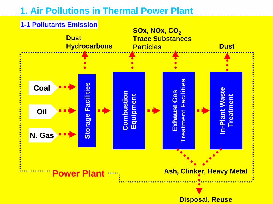
1. Air Pollutions in Thermal Power Plant
Power Plant
DustHydrocarbons
SOx, NOx, CO2Trace SubstancesParticles Dust
Stor
age
Faci
litie
s
Com
bust
ion
Equi
pmen
t
Exha
ust G
asTr
eatm
ent F
acili
ties
In-P
lant
Was
teTr
eatm
ent
Coal
N. Gas
Oil
Ash, Clinker, Heavy Metal
Disposal, Reuse
1-1 Pollutants Emission
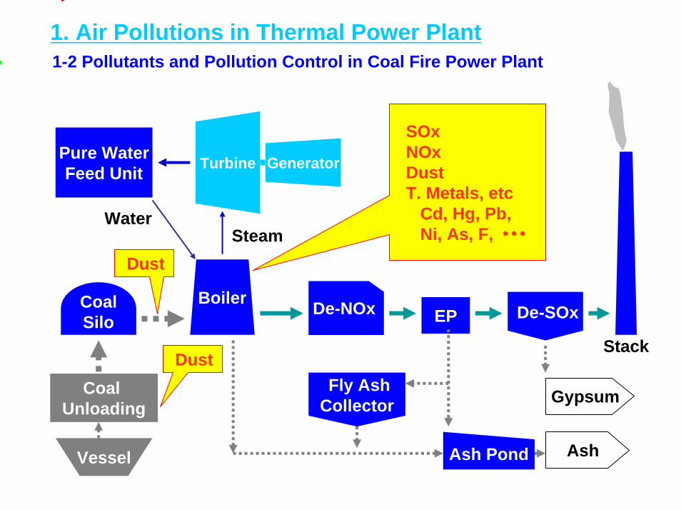
1. Air Pollutions in Thermal Power Plant1-2 Pollutants and Pollution Control in Coal Fire Power Plant
Pure WaterFeed Unit
Coal Unloading
Ash Pond
Fly AshCollector
BoilerCoalSilo
De-NOx EP De-SOx
Stack
SOxNOxDustT. Metals, etc
Cd, Hg, Pb,Ni, As, F, ・・・
Turbine
Steam
Generator
Gypsum
Ash
Water
Dust
Vessel
Dust
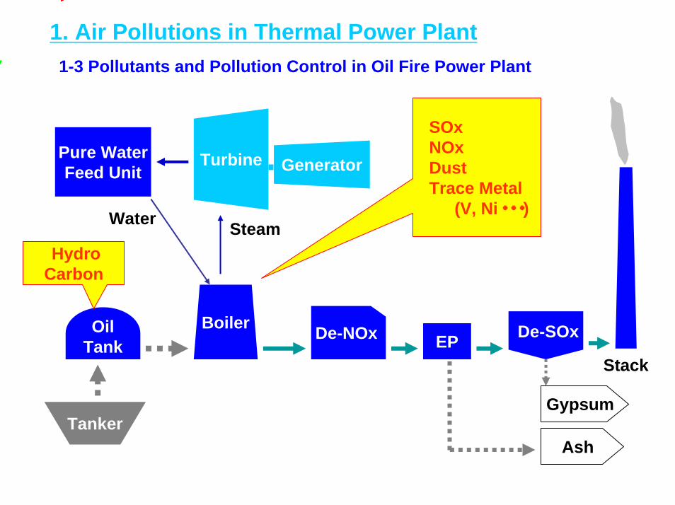
1. Air Pollutions in Thermal Power Plant1-3 Pollutants and Pollution Control in Oil Fire Power Plant
Pure WaterFeed Unit
BoilerOilTank
De-NOx EP De-SOx
Stack
SOxNOxDustTrace Metal
(V, Ni・・・)
Turbine
Steam
Generator
Gypsum
Ash
Water
Hydro Carbon
Tanker
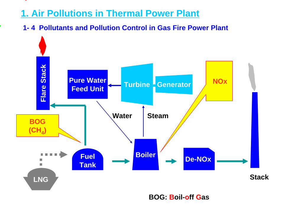
1. Air Pollutions in Thermal Power Plant1- 4 Pollutants and Pollution Control in Gas Fire Power Plant
Pure WaterFeed Unit
BoilerFuelTank
De-NOx
Stack
NOx
SteamWater
Turbine Generator
BOG(CH4)
LNG
Flar
e St
ack
BOG: Boil-off Gas

2. Measures against Fuel2-1 Coal Fire Power Plant
Dus
t
Dus
t
Dus
t
Dus
t
relaysection
unloader stacker reclaimer
conveyor
coal
dust ∝ v 4~5
water spray
windshield netor
windbreak forestdust cover
windshieldplate
water spray6~12 % water,(surfactant)
surface compaction
Dust collector
Dust Control
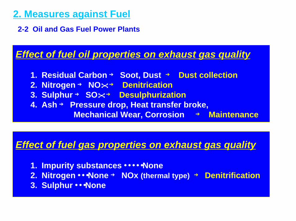
2. Measures against Fuel2-2 Oil and Gas Fuel Power Plants
Effect of fuel oil properties on exhaust gas quality
1. Residual Carbon → Soot, Dust → Dust collection2. Nitrogen → NOx → Denitrication3. Sulphur→ SOx → Desulphurization4. Ash → Pressure drop, Heat transfer broke,
Mechanical Wear, Corrosion → Maintenance
Effect of fuel gas properties on exhaust gas quality
1. Impurity substances・・・・・None2. Nitrogen・・・None → NOx (thermal type) → Denitrification3. Sulphur・・・None
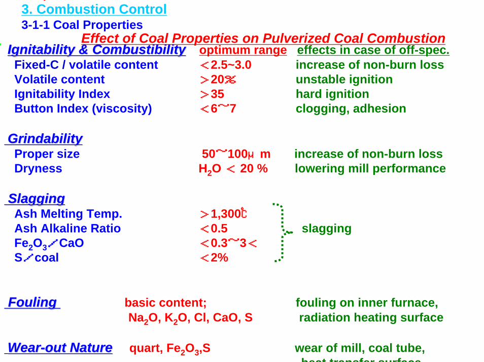
Ignitability & CombustibilityIgnitability & Combustibility optimum range effects in case of off-spec.Fixed-C / volatile content <2.5~3.0 increase of non-burn lossVolatile content >20% unstable ignitionIgnitability Index >35 hard ignitionButton Index (viscosity) <6~7 clogging, adhesion
GrindabilityGrindabilityProper size 50~100μm increase of non-burn lossDryness H2O < 20 % lowering mill performance
SlaggingSlaggingAsh Melting Temp. >1,300℃Ash Alkaline Ratio <0.5 slaggingFe2O3/CaO <0.3~3<S/coal <2%
Fouling Fouling basic content; fouling on inner furnace,Na2O, K2O, Cl, CaO, S radiation heating surface
WearWear--out Natureout Nature quart, Fe2O3,S wear of mill, coal tube,heat transfer surface
3. Combustion Control3-1-1 Coal Properties
Effect of Coal Properties on Pulverized Coal Combustion

3. Combustion Control3-1-2 Coal Combustion
Low NOx Combustion 1. Reduction of surplus air ratio (high volatile coal; 1.2~1.25) 2. Lowering combustion air temp. (normally 250~350 ℃)3. Two stage combustion (1st burner + 2nd burner)4. Recycling exhaust gas (<20~30%)5. Inner-furnace denitrification6. Low NOx burner
1st Process― furnace >900℃ HC decomposition― O2 existing― reductant HC > chemical equivalent O2
2nd Process― atmosphere temp. > reaction temp. of
non-burned portion― sufficient O2
― slow mixture air & fuel― promotion of unevenness comb.― acceleration of flame heat radiation
Combustion Mechanism of Pulverized Coal
VolatileCH4, H2, CO
CoalChar
radiation ignition temp.<750℃

3. Combustion Control3-2-1 Oil Combustion
Effect of Fuel Oil Properties on Exhaust Gas Composition
Scaling, Vanadium attack,corrosion, mechanical wear, etc.
Adherents < 0.02※Ash(Na, K, V, ----)
Dust, carbon adhereDust4.0~11.5 ※Red. C
Air pollution, corrosionclogging
SO2,SO3→SO4
(SOx)0.2~3.0※S
Air pollutionNOx0.01~0.6NSubs. Con. wt% Pollutants Damages
Surface Combustion
Comb. reaction ∝ oil jet speed∝ combustion speed
oilair
heat
high spraying burner
vaporized sub.solids
Evaporation Comb.Flame Combustion … + Decomposition Comb.Oil Combustion Mechanism
※JIS C-Heavy Oil

3. Combustion Control3-2-2 Oil - NOx Generation
Generation
Thermal NOx (N in Air)Flame temp.O2 concentrationRetention time
Fuel NOx (N in Fuel)O2 concentrationNitrogen in fuel
Control Measures
・2-stage combustion・Exhaust gas recycling・Low NOx burner・Furnace size expansion
NOx Generation and its Control in Oil Combustion
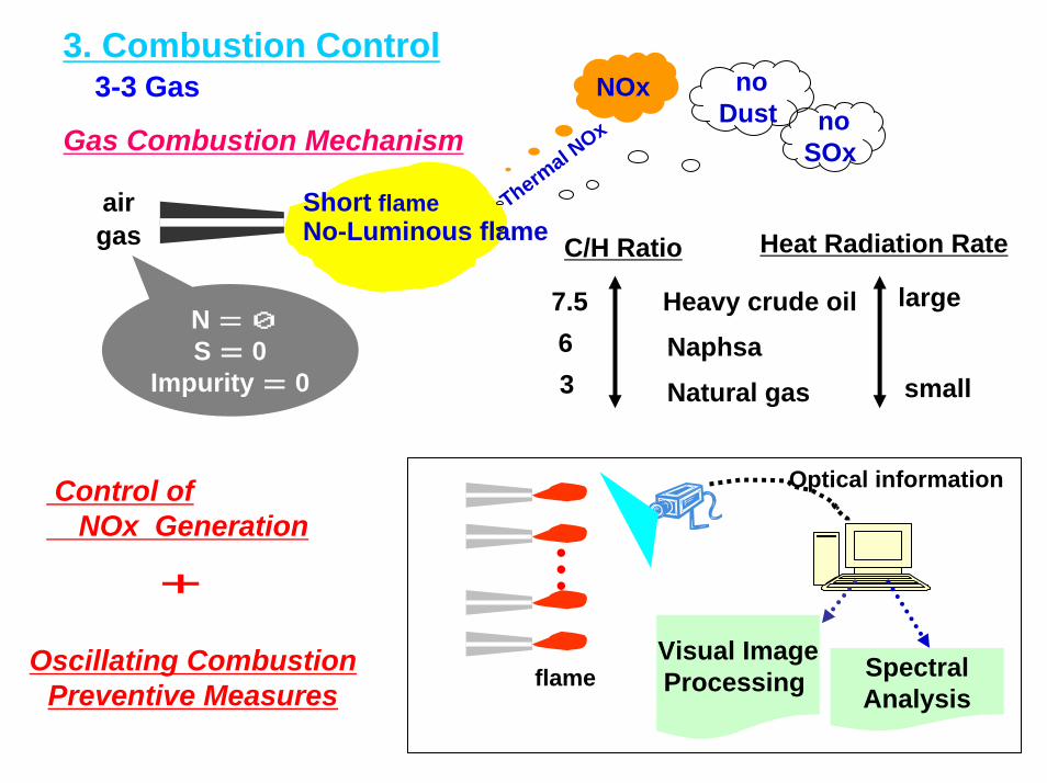
3. Combustion Control3-3 Gas
airgas
Short flameNo-Luminous flame Heat Radiation Rate
large
small
C/H Ratio
7.563
Heavy crude oilNaphsa
Natural gas
noSOx
NOx noDust
N = 0S = 0
Impurity = 0
Thermal N
OxGas Combustion Mechanism
SpectralAnalysis
Visual ImageProcessing
Optical information
flame
Control ofNOx Generation
+
Oscillating CombustionPreventive Measures
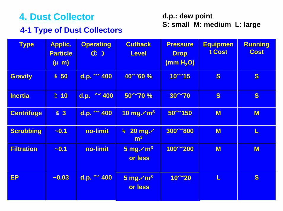
4. Dust Collector4-1 Type of Dust Collectors
d.p.: dew pointS: small M: medium L: large
SL10~205 mg/m3
or lessd.p. ~ 400~0.03EP
MM100~2005 mg/m3
or lessno-limit~0.1Filtration
LM300~800≒ 20 mg/m3
no-limit~0.1Scrubbing
MM50~15010 mg/m3d.p. ~ 400≧3Centrifuge
SS30~7050~70 %d.p. ~ 400≧10Inertia
SS10~1540~60 %d.p. ~ 400≧50Gravity
Running Cost
Equipment Cost
PressureDrop
(mm H2O)
CutbackLevel
Operating ( ℃)
Applic.Particle(μm)
Type
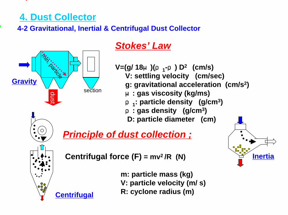
4-2 Gravitational, Inertial & Centrifugal Dust Collector
min. particledust
sectionGravity
Stokes’ Law
V=(g/ 18μ)(ρ1-ρ) D2 (cm/s)V: settling velocity (cm/sec)g: gravitational acceleration (cm/s2)μ: gas viscosity (kg/ms) ρ1: particle density (g/cm3)ρ: gas density (g/cm3)D: particle diameter (cm)
Principle of dust collection ;
Centrifugal force (F) = mv2 /R (N)
m: particle mass (kg)V: particle velocity (m/ s)R: cyclone radius (m)
Inertia
4. Dust Collector
Centrifugal
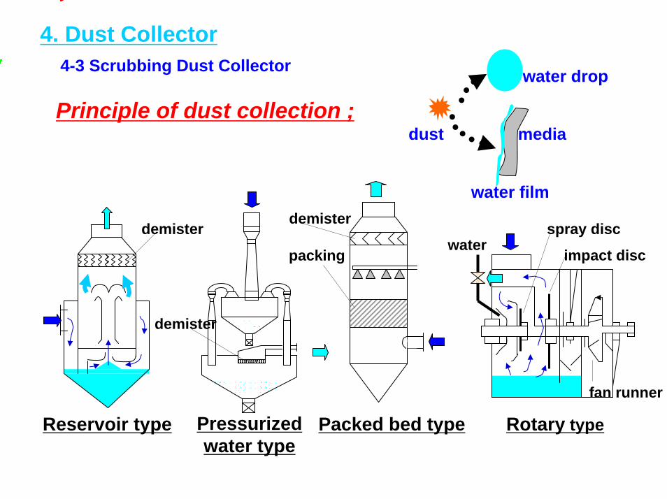
4. Dust Collector4-3 Scrubbing Dust Collector
Principle of dust collection ;
Pressurizedwater type
Reservoir type Packed bed type
demister
demisterdemister
packing
fan runner
dust
water drop
water film
media
Rotary type
waterspray disc
impact disc
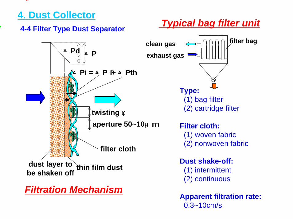
4. Dust Collector4-4 Filter Type Dust Separator
filter cloth
dust layer tobe shaken off
thin film dust
△Pi = △Pf + △Pth
△P△Pd
twisting φaperture 50~10μm
Filtration Mechanism
Typical bag filter unit
Type: (1) bag filter(2) cartridge filter
Filter cloth:(1) woven fabric(2) nonwoven fabric
Dust shake-off:(1) intermittent(2) continuous
Apparent filtration rate: 0.3~10cm/s
filter bag
exhaust gas
clean gas

4. Dust Collector4-5-1 Electrostatic Precipitator (EP)
-
- - --
----
--
--
-
discharge electrode
dust
col
lect
ing
elec
trod
e
--
Principle of dust collection
--
-
Exhaust gas properties;
Heavy oil Coalinlet soot & dust g/Nm3 0.05~0.15 10~20dust φ μm 1~3 20~30SiO2 Wt % 15~20 60~75C Wt % 50~60 0.4~0.8ρ Rate Ω・cm 104~106 1011~1013
apparent S.G. g/ml 0.1~0.2 0.6~0.8
Influence on dust collection
・SO3 mist
・temperature・water・SO3 mist・composition of dust
・NH3 injection
・tempering flue gas・electric charge control・dust removal on (+) electrode・selection of gas temp.
Improving method
Appropriateρ
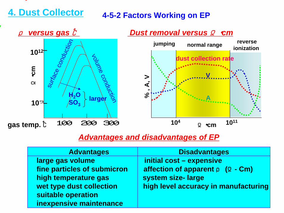
Advantages Disadvantageslarge gas volume initial cost – expensivefine particles of submicron affection of apparent ρ (Ω- Cm)high temperature gas system size- largewet type dust collection high level accuracy in manufacturingsuitable operationinexpensive maintenance
4. Dust Collector 4-5-2 Factors Working on EP
jumping normal range reverseionization
dust collection rate
A
V
104 1011Ω・cm
% ,
A, V
Dust removal versus Ω・cmρ versus gas ℃
H2OSO3
larger
surfa
ce c
ondu
ctio
n
volume conduction
Ω・cm
1012
109―
―
gas temp. ℃ 300200100
Advantages and disadvantages of EP
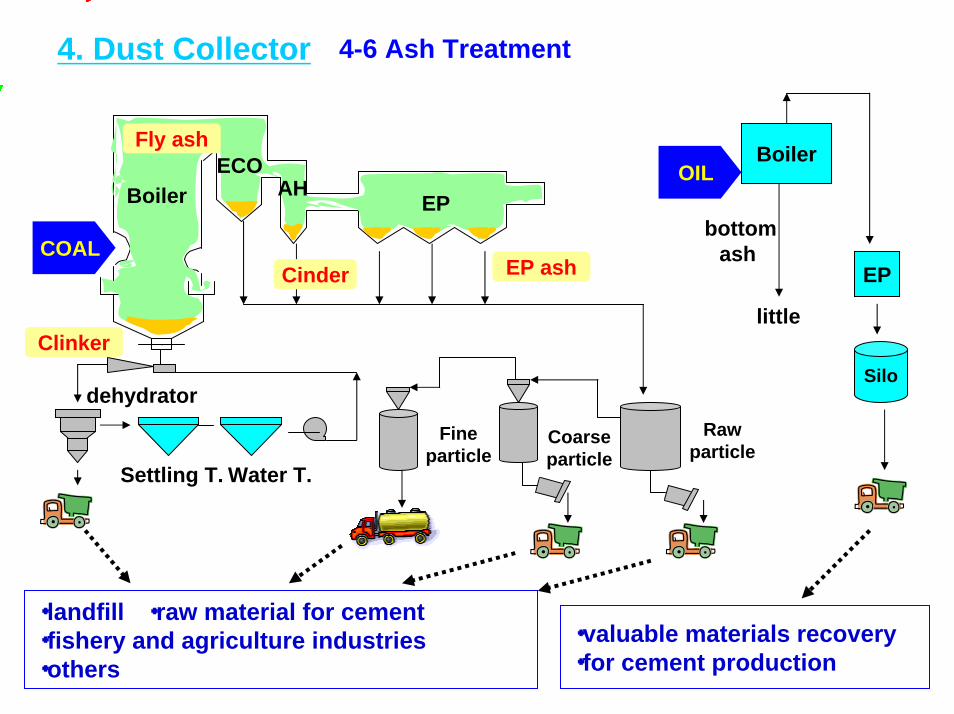
4. Dust Collector 4-6 Ash Treatment
Boiler
EP
OIL
Silo
bottomash
little
・valuable materials recovery・for cement production
・landfill ・raw material for cement ・fishery and agriculture industries ・others
Rawparticle
Boiler EPAH
ECO
Fineparticle
Water T.Settling T.
Coarseparticle
Cinder
Fly ash
EP ash
Clinker
COAL
dehydrator
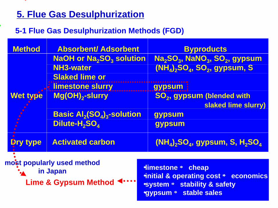
5. Flue Gas Desulphurization5-1 Flue Gas Desulphurization Methods (FGD)
Method Absorbent/ Adsorbent ByproductsNaOH or Na2SO3 solution Na2SO3, NaNO3, SO2, gypsumNH3-water (NH4)2SO4, SO2, gypsum, SSlaked lime orlimestone slurry gypsum
Wet type Mg(OH)2-slurry SO2, gypsum (blended withslaked lime slurry)
Basic Al2(SO4)3-solution gypsumDilute-H2SO4 gypsum
Dry type Activated carbon (NH4)2SO4, gypsum, S, H2SO4
・limestone ⇒ cheap・initial & operating cost ⇒ economics・system ⇒ stability & safety ・gypsum ⇒ stable sales
Lime & Gypsum Method
most popularly used method in Japan
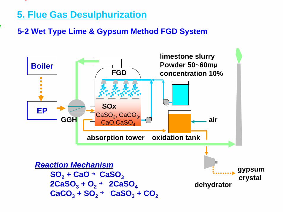
5. Flue Gas Desulphurization5-2 Wet Type Lime & Gypsum Method FGD System
Reaction MechanismSO2 + CaO→CaSO32CaSO3 + O2→ 2CaSO4CaCO3 + SO2→ CaSO3 + CO2
Boiler
EP
gypsumcrystal
GGH
dehydrator
SOx
limestone slurryPowder 50~60mμconcentration 10%
CaSO3, CaCO3,CaO,CaSO4
oxidation tank
FGD
air
absorption tower

5. Flue Gas Desulphurization5-3 Simplified FGD System
Simplified FGDLime & Gypsum Semi-dry Method
Method Intrafurnace Desulphurization+ Water Spray Method
Alkali Ca CO3 powder CaCO3 powderSO2 + H2O → H2SO4 CaCO3→ CaO + CO2
Reaction H2SO3 + 1/2O2→ H2SO4 SO2 + CaO + 1/2O2→ CaSO4CaCO3 + H2SO4 + H2O SO2 + CaO + 1/2H2O → CaSO4 + 2H2O + CO2 → CaSO3 + 1/2H2O☆useful gypsum ☆no wastewater
Advantages ☆large flue gas ☆compact size, less space ☆high-level removal ☆simple process, excellent in economics★wastewater treatment ★slagging inside boiler
Disadvantages ★anticorrosion material ★lower removal ★large area ★lower alkali utilization★high maintenance cost
CostEquipment 100 20~30Operation 100 75~80
Comparison of Simplified FGD with Conventional FGD
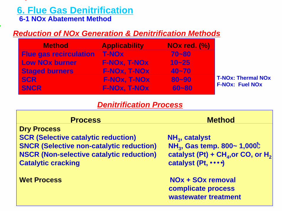
6. Flue Gas Denitrification6-1 NOx Abatement Method
Method Applicability NOx red. (%)Flue gas recirculation T-NOx 70~80Low NOx burner F-NOx, T-NOx 10~25Staged burners F-NOx, T-NOx 40~70SCR F-NOx, T-NOx 80~90SNCR F-NOx, T-NOx 60~80
T-NOx: Thermal NOxF-NOx: Fuel NOx
Process MethodDry ProcessSCR (Selective catalytic reduction) NH3, catalyst SNCR (Selective non-catalytic reduction) NH3, Gas temp. 800~ 1,000℃NSCR (Non-selective catalytic reduction) catalyst (Pt) + CH4,or CO, or H2Catalytic cracking catalyst (Pt,・・・・)
Wet Process NOx + SOx removalcomplicate processwastewater treatment
Reduction of NOx Generation & Denitrification Methods
Denitrification Process
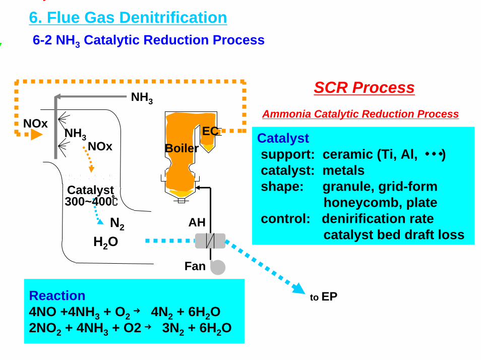
6. Flue Gas Denitrification6-2 NH3 Catalytic Reduction Process
Catalystsupport: ceramic (Ti, Al, ・・・)catalyst: metalsshape: granule, grid-form
honeycomb, platecontrol: denirification rate
catalyst bed draft loss
BoilerNH3 ECNOx
NH3
Fan
NOx
Catalyst
H2ON2 AH
to EP
300~400℃
Reaction4NO +4NH3 + O2→ 4N2 + 6H2O2NO2 + 4NH3 + O2 → 3N2 + 6H2O
SCR ProcessAmmonia Catalytic Reduction Process
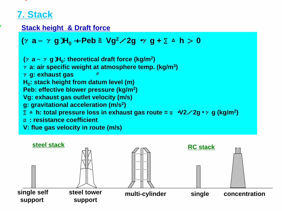
7. StackStack height & Draft force
(γa―γg)H0+Peb≧Vg2/2g ・γg + ∑△h > 0
(γa―γg)H0: theoretical draft force (kg/m2)γa: air specific weight at atmosphere temp. (kg/m3)γg: exhaust gas 〃H0: stack height from datum level (m)Peb: effective blower pressure (kg/m2)Vg: exhaust gas outlet velocity (m/s)g: gravitational acceleration (m/s2)∑△h: total pressure loss in exhaust gas route = α・V2/2g・ γg (kg/m2)α: resistance coefficientV: flue gas velocity in route (m/s)
single selfsupport
RC stack
singlemulti-cylindersteel tower support
steel stack
concentration
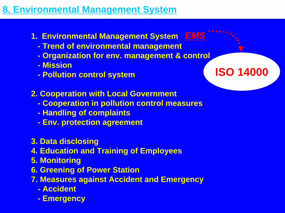
8. Environmental Management System
1. Environmental Management System EMS - Trend of environmental management- Organization for env. management & control- Mission- Pollution control system
2. Cooperation with Local Government- Cooperation in pollution control measures- Handling of complaints- Env. protection agreement
3. Data disclosing 4. Education and Training of Employees5. Monitoring6. Greening of Power Station7. Measures against Accident and Emergency
- Accident- Emergency
ISO 14000
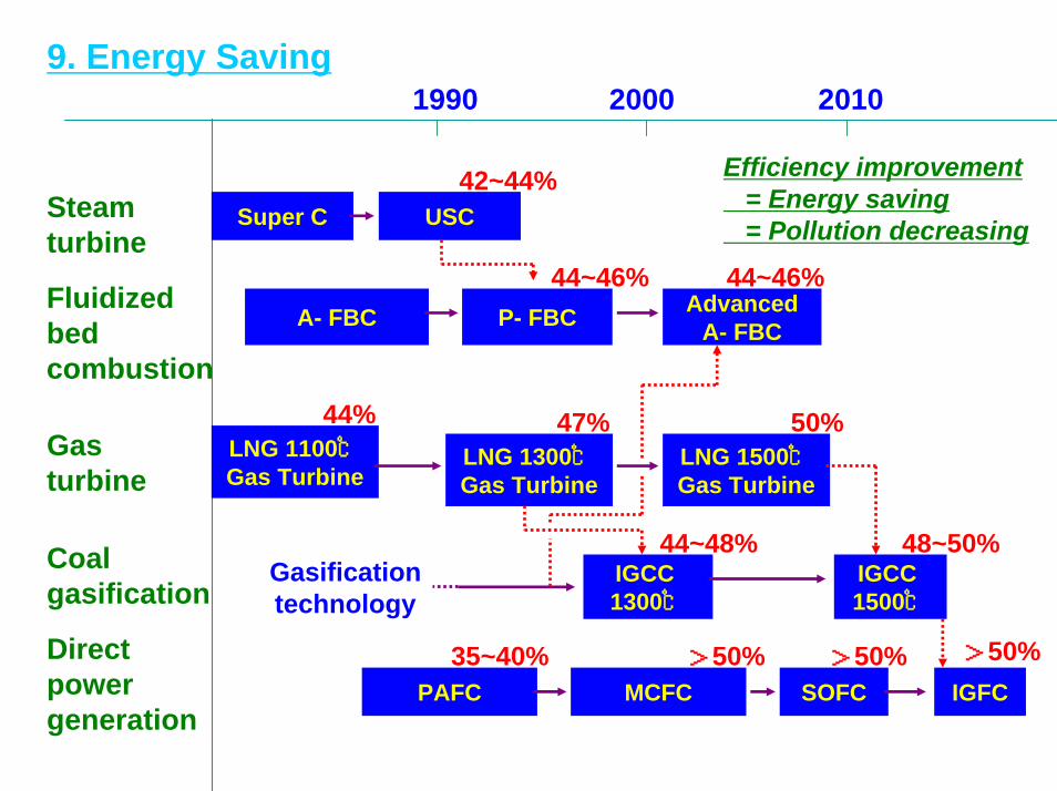
9. Energy Saving
Super C USC
A- FBC AdvancedA- FBCP- FBC
LNG 1100℃Gas Turbine
LNG 1300℃Gas Turbine
LNG 1500℃Gas Turbine
IGCC 1300℃
IGCC 1500℃
PAFC MCFC SOFC IGFC
20001990 2010
Steamturbine
Fluidizedbedcombustion
Gasturbine
Coalgasification
Directpowergeneration
Gasificationtechnology
47%
42~44%
44~46% 44~46%
44% 50%
44~48% 48~50%
35~40% >50% >50% >50%
Efficiency improvement = Energy saving = Pollution decreasing