Theoretical and Applied Fracture Mechanics - Texas … Department of Geotechnical Engineering, ......
12
Mixed-mode fracture & non-planar fatigue analyses of cracked I-beams, using a 3D SGBEM–FEM Alternating Method Longgang Tian a,b , Leiting Dong c,⇑ , Sharada Bhavanam b , Nam Phan d , Satya N. Atluri b a Department of Geotechnical Engineering, College of Civil Engineering, Tongji University, Shanghai 200092, China b Center for Aerospace Research & Education, University of California, Irvine, USA c Department of Engineering Mechanics, Hohai University, Nanjing, China d Structures Division, Naval Air Systems Command, Patuxent River, MD, USA article info Article history: Available online 18 October 2014 Keywords: SGBEM–FEM Alternating Method I-beam Stress intensity factor Fatigue crack growth abstract In the present paper, computations of mixed mode stress intensity factor (SIF) variations along the crack front, and fatigue-crack-growth simulations, in cracked I-beams, considering different load cases and initial crack configurations, are carried out by employing the three-dimensional SGBEM (Symmetric Galerkin Boundary Element Method)–FEM (Finite Element Method) Alternating Method. For mode-I cracks in the I-beam, the computed SIFs by using the SGBEM–FEM Alternating Method are in very good agreement with available empirical solutions. The predicted fatigue life of cracked I-beams agrees well with experimental observations in the open literature. For mixed-mode cracks in the web or in the flange of the I-beams, no analytical or empirical solutions are available in the literature. Thus mixed-mode SIFs for mixed-mode web and flange cracks are presented, and non-planar fatigue growth simulations are given, as benchmark examples for future studies. Moreover, because very minimal efforts of preprocess- ing and very small computational burden are needed, the current SGBEM–FEM Alternating Method is very suitable for fracture and fatigue analyses of 3D structures such as I-beams. Ó 2014 Elsevier Ltd. All rights reserved. 1. Introduction The calculation of fracture mechanics parameters (such as the Mode I, II and III stress intensity factors), for arbitrary surface and embedded cracks in complex 3D structures, remains an impor- tant task for the structural integrity assessment and damage toler- ance analyses [1]. The application of linear elastic fracture mechanics to fracture and fatigue analyses of various types of structures has been hindered by the lack of analytical solutions of stress intensity factors, which characterize the magnitude of the singular stress field near the crack-tip/crack-front. The strength of a cracked structure and the fatigue crack growth rate under cyc- lic loading can be determined once the corresponding stress inten- sity factors are computed. A rational fatigue life estimation of the cracked structure can be made based on these analyses, for the design, maintenance and damage tolerance of civil, mechanical and aerospace structures. I-beams are widely used as typical structural components in structural engineering. Since the I-beam has the characteristics of both three-dimensional finite bodies as well as slender bars, it is quite difficult to find the exact solution for stress intensity factors for cracked I-beams by the existing classical analytical methods. By applying the conservation laws and elementary beam theory, Kien- zler and Hermann [2] obtained the approximate stress intensity factors for cracked beams with different crack geometries and a rectangular cross section. Hermann and Sosa [3] applied the method in [2] to find the stress intensity factors of cracked pipes under different loading conditions. The stress intensity factors are normally expressed as a function of the finite-size correction factor b in literature [2]. Gao and Hermann [4] applied asymptotic techniques based on the method introduced in [2] to calculate a better approximation for the correction factor b. Müller et al. [5] extended the method of Kienzler and Hermann [2] to assess the stress intensity factors of circumferentially cracked cylinders and rectangular beams under different loading conditions. Dunn et al. [6] calculated the stress intensity factors of I-beams under a bend- ing moment, by extending the work of [2] along with dimensional considerations and a finite element calibration. Another approach for determining stress intensity factors of engineering structures is by using the G ⁄ -integral, based on conser- vation laws and the concept of crack surface widening energy release rate. Xie et al. [7–9] showed that the crack surface widening energy release rate can be expressed by the G ⁄ -integral along with http://dx.doi.org/10.1016/j.tafmec.2014.10.002 0167-8442/Ó 2014 Elsevier Ltd. All rights reserved. ⇑ Corresponding author. E-mail address: [email protected] (L. Dong). Theoretical and Applied Fracture Mechanics 74 (2014) 188–199 Contents lists available at ScienceDirect Theoretical and Applied Fracture Mechanics journal homepage: www.elsevier.com/locate/tafmec
-
Upload
nguyenxuyen -
Category
Documents
-
view
218 -
download
2
Transcript of Theoretical and Applied Fracture Mechanics - Texas … Department of Geotechnical Engineering, ......

Theoretical and Applied Fracture Mechanics 74 (2014) 188–199
Contents lists available at ScienceDirect
Theoretical and Applied Fracture Mechanics
journal homepage: www.elsevier .com/locate / tafmec
Mixed-mode fracture & non-planar fatigue analyses of cracked I-beams,using a 3D SGBEM–FEM Alternating Method
http://dx.doi.org/10.1016/j.tafmec.2014.10.0020167-8442/� 2014 Elsevier Ltd. All rights reserved.
⇑ Corresponding author.E-mail address: [email protected] (L. Dong).
Longgang Tian a,b, Leiting Dong c,⇑, Sharada Bhavanam b, Nam Phan d, Satya N. Atluri b
a Department of Geotechnical Engineering, College of Civil Engineering, Tongji University, Shanghai 200092, Chinab Center for Aerospace Research & Education, University of California, Irvine, USAc Department of Engineering Mechanics, Hohai University, Nanjing, Chinad Structures Division, Naval Air Systems Command, Patuxent River, MD, USA
a r t i c l e i n f o
Article history:Available online 18 October 2014
Keywords:SGBEM–FEM Alternating MethodI-beamStress intensity factorFatigue crack growth
a b s t r a c t
In the present paper, computations of mixed mode stress intensity factor (SIF) variations along the crackfront, and fatigue-crack-growth simulations, in cracked I-beams, considering different load cases andinitial crack configurations, are carried out by employing the three-dimensional SGBEM (SymmetricGalerkin Boundary Element Method)–FEM (Finite Element Method) Alternating Method. For mode-Icracks in the I-beam, the computed SIFs by using the SGBEM–FEM Alternating Method are in very goodagreement with available empirical solutions. The predicted fatigue life of cracked I-beams agrees wellwith experimental observations in the open literature. For mixed-mode cracks in the web or in the flangeof the I-beams, no analytical or empirical solutions are available in the literature. Thus mixed-mode SIFsfor mixed-mode web and flange cracks are presented, and non-planar fatigue growth simulations aregiven, as benchmark examples for future studies. Moreover, because very minimal efforts of preprocess-ing and very small computational burden are needed, the current SGBEM–FEM Alternating Method isvery suitable for fracture and fatigue analyses of 3D structures such as I-beams.
� 2014 Elsevier Ltd. All rights reserved.
1. Introduction
The calculation of fracture mechanics parameters (such as theMode I, II and III stress intensity factors), for arbitrary surfaceand embedded cracks in complex 3D structures, remains an impor-tant task for the structural integrity assessment and damage toler-ance analyses [1]. The application of linear elastic fracturemechanics to fracture and fatigue analyses of various types ofstructures has been hindered by the lack of analytical solutionsof stress intensity factors, which characterize the magnitude ofthe singular stress field near the crack-tip/crack-front. The strengthof a cracked structure and the fatigue crack growth rate under cyc-lic loading can be determined once the corresponding stress inten-sity factors are computed. A rational fatigue life estimation of thecracked structure can be made based on these analyses, for thedesign, maintenance and damage tolerance of civil, mechanicaland aerospace structures.
I-beams are widely used as typical structural components instructural engineering. Since the I-beam has the characteristics ofboth three-dimensional finite bodies as well as slender bars, it is
quite difficult to find the exact solution for stress intensity factorsfor cracked I-beams by the existing classical analytical methods. Byapplying the conservation laws and elementary beam theory, Kien-zler and Hermann [2] obtained the approximate stress intensityfactors for cracked beams with different crack geometries and arectangular cross section. Hermann and Sosa [3] applied themethod in [2] to find the stress intensity factors of cracked pipesunder different loading conditions. The stress intensity factorsare normally expressed as a function of the finite-size correctionfactor b in literature [2]. Gao and Hermann [4] applied asymptotictechniques based on the method introduced in [2] to calculate abetter approximation for the correction factor b. Müller et al. [5]extended the method of Kienzler and Hermann [2] to assess thestress intensity factors of circumferentially cracked cylinders andrectangular beams under different loading conditions. Dunn et al.[6] calculated the stress intensity factors of I-beams under a bend-ing moment, by extending the work of [2] along with dimensionalconsiderations and a finite element calibration.
Another approach for determining stress intensity factors ofengineering structures is by using the G⁄-integral, based on conser-vation laws and the concept of crack surface widening energyrelease rate. Xie et al. [7–9] showed that the crack surface wideningenergy release rate can be expressed by the G⁄-integral along with

Fig. 1. A solution domain with source point x and target point n.
L. Tian et al. / Theoretical and Applied Fracture Mechanics 74 (2014) 188–199 189
elementary strength of materials theory for slender cracked struc-tures. They applied the G⁄-integral to calculate the stress intensityfactors of thin-walled tubes with a cracked rectangular cross sec-tion, and they also applied this method to analyze homogeneousand composite multi-channel beams [10]. Kishen and Kumar [11]employed a cracked beam-column element, introduced by Tharp[12], in a finite element simulation to study the fracture behaviorof cracked beam-columns with different load eccentricities.
It should be noted that, all the above-mentioned analytical orempirical solutions can only be used for analyzing symmetricmodel-I cracks in I-beams. They are not valid for fatigue crackgrowth simulations of mixed-mode cracks in I-beam, such as theinclined cracks in the flanges. Numerical methods are necessaryfor fracture and fatigue analyses of mixed-mode cracks in complex3D structures.
In spite of its wide-spread popularity, the traditional Finite Ele-ment Method (FEM), with simple polynomial interpolations, isunsuitable for modeling cracks and their propagations. This is par-tially due to the high-inefficiency of approximating stress & strain-singularities using polynomial FEM shape functions. In order toovercome this difficulty, embedded-singularity elements by Tonget al. [13], Atluri et al. [14], and singular quarter-point elementsby Henshell and Shaw [15] and Barsoum [16], were developed inorder to capture the crack-tip/crack-front singular field. Many suchrelated developments were summarized in the monograph byAtluri [17] and they are now widely available in many commercialFEM software. However, the need for constant re-meshing makesthe automatic fatigue-crack-growth analyses, using traditionalFEM, to be very difficult.
In a fundamentally different mathematical way, after the deri-vation of a complete analytical solution for an embedded ellipticalcrack in an infinite body whose faces are subjected to arbitrarytractions [19], the first paper on a highly-accurate Finite Element(Schwartz–Neumann) Alternating Method (FEAM) was publishedby Nishioka and Atluri [18]. The FEAM uses the Schwartz–Neu-mann alternation between a crude and simple finite element solu-tion for an uncracked structure, and the analytical solution for thecrack embedded in an infinite body. Subsequent 2D and 3D vari-ants of the Finite Element Alternating Methods were successfullydeveloped and applied to perform structural integrity and damagetolerance analyses of many practical engineering structures [1].Recently, the SGBEM (Symmetric Galerkin Boundary ElementMethod)–FEM (Finite Element Method) Alternating Method, whichinvolves the alternation between the very crude FEM solution ofthe uncracked structure, and an SGBEM solution for a small regionenveloping the arbitrary non-planar 3D crack, was developed forarbitrary three-dimensional non-planar growth of embedded aswell as surface cracks by Nikishkov et al. [20], and Han and Atluri[21]. An SGBEM ‘super element’ was also developed in Dong andAluri [22–25] for the direct coupling of SGBEM and FEM in fractureand fatigue analysis of complex 2D & 3D solid structures and mate-rials. The motivation for this series of works, by Atluri and many ofhis collaborators since the 1980s, is to explore the advantageousfeatures of each computational method: model the complicateduncracked structures with simple FEMs, and model the crack-sin-gularities by mathematical methods such as complex variables,special functions, boundary integral equations (BIEs), and bySGBEMs.
In the present paper, by employing the SGBEM–FEM AlternatingMethod, the stress intensity factors of I-beams with different crackconfigurations are computed; fatigue-crack-growth process of theI-beams subjected to cyclic loadings are examined. The stressintensity factors of the crack-front are computed during each stepof crack increment. Crack growth rates are determined by the ParisLaw. The crack paths and number of loading cycles are predictedfor damage tolerance evaluation. The validations of SGBEM–FEM
Alternating Method are illustrated by the comparison of numericalresults with available empirical solutions as well as experimentalobservations. For mode-I cracks in the I-beam, the computed SIFsby using the SGBEM–FEM Alternating Method are in very goodagreement with empirical solutions. And the predicted fatigue lifeof cracked I-beams agrees well with experimental observations inthe open literature. For inclined cracks in the web or in the flangeof the I-beams, no analytical or empirical solutions are available inthe literature. Thus mixed-mode SIFs of inclined web and flangecracks are presented and non-planar fatigue growth simulationsare given, as benchmark examples for future investigators.
2. SGBEM–FEM Alternating Method: theory and formulation
The Symmetric Galerkin Boundary Element Method (SGBEM)has several advantages over traditional and dual BEMs by Rizzo[26], Hong and Chen [27], such as resulting in a symmetrical coef-ficient matrix of the system of equations, and the avoidance of theneed to treat sharp corners specially. Early derivations of SGBEMsinvolve regularization of hyper-singular integrals, see the work byFrangi and Novati [28]; Bonnet et al. [29]; Li et al. [30]; Frangi et al.[31]. A systematic procedure to develop weakly-singular symmet-ric Galerkin boundary integral equations was presented by Hanand Atluri [32,33]. The derivation of this simple formulationinvolves only the non-hyper singular integral equations for trac-tions, based on the original work reported in Okada et al. [34,35].It was used to analyze cracked 3D solids with surface flaws byNikishkov et al. [20] and Han and Atluri [21].
For a domain of interest as shown in Fig. 1, with source point xand target point n, 3D weakly-singular symmetric Galerkin BIEs fordisplacements and tractions are developed by Han and Atluri [32].
The displacement BIE is:12
Z@X
vpðxÞupðxÞdSx ¼Z@X
vpðxÞdSx
Z@X
tjðnÞu�pj x; nð ÞdSn
þZ@X
vpðxÞdSx
Z@X
DiðnÞujðnÞG�pij x; nð ÞdSn
þZ@X
vpðxÞdSx
Z@X
niðnÞujðnÞu�pij x; nð ÞdSn ð1Þ
And the corresponding traction BIE is:
�12
Z@X
wbðxÞtbðxÞdSx ¼Z@X
DaðxÞwbðxÞdSx
Z@X
tqðnÞG�qab x;nð ÞdSn
�Z@X
wbðxÞdSx
Z@X
naðxÞtqðnÞu�qab x;nð ÞdSn
þZ@X
DaðxÞwbðxÞdSx
Z@X
DpðnÞuqðnÞH�abpq x;nð ÞdSn
ð2Þ

190 L. Tian et al. / Theoretical and Applied Fracture Mechanics 74 (2014) 188–199
In Eqs. (1) and (2), Da is a surface tangential operator:
Da nð Þ ¼ nr nð Þersa@
@ns
Da xð Þ ¼ nr xð Þersa@
@xs
ð3Þ
Kernels functions u�pj ;G�qab;u
�qab;H
�abpq can be found in the paper by
Han and Atluri [32], which are all weakly-singular, making theimplementation of the current BIEs very simple.
Fig. 2. A defective solid with arbitrary cavities and cracks.
Fig. 3. Superposition principle for SGBEM–FEM Alternating Method: (a) the uncrackedSGBEM, (c) FEM model subjected to residual stresses, and (d) alternating solution for th
As shown in Fig. 2, By applying Eq. (1) to Su, where displace-ments are prescribed, and applying Eq. (2) to St, where tractionsare prescribed, a symmetric system of equations can be obtained:
App Apq Apr
Aqp Aqq Aqr
Arp Arq Arr
264
375
pqr
8><>:
9>=>; ¼
fp
fq
fr
8><>:
9>=>; ð4Þ
where p, q, r denotes the unknown tractions at Su, unknown dis-placements at S0t , and unknown displacement discontinuities at Sc
respectively.With the displacements and tractions being first determined at
the boundary and crack surface, the displacements, strains andstress at any point in the domain can be computed using thenon-hyper singular BIEs in the paper by Okada et al. [34,35]. There-fore, the path-independent or domain-independent integrals canbe used to compute the stress intensity factors. Alternatively, withthe singular quarter-point boundary elements at the crack face,stress intensity factors can also be directly computed using the dis-placement discontinuity at the crack-front elements, see the paperby Nikishkov et al. [20] for detailed discussion. For fatigue growthof cracks, there is no need to use any other special technique todescribe the crack surface, such as the Level Sets. The crack surfaceis already efficiently described by boundary elements. In each fati-gue step, a minimal effort is needed: one can simply extend thecrack by adding a layer of additional elements at the crack-tip/crack-front. This greatly saves the computational time for fati-gue-crack-growth analyses.
However, the SGBEM is unsuitable for carrying out large scalesimulation of complex structures. This is because of the fact thatthe coefficient matrix for SGBEM is fully-populated. To furtherexplore the advantages of both FEM and SGBEM, Han and Atluri[21] coupled FEM and SGBEM indirectly, using the Schwartz–Neu-mann Alternating Method. As shown in Fig. 3, simple FEM is used
body modeled by simple FEM, (b) the local domain containing cracks modeled bye original problem.

L. Tian et al. / Theoretical and Applied Fracture Mechanics 74 (2014) 188–199 191
to model the uncracked global structure, and SGBEM is used tomodel the local cracked subdomain. By imposing residual stressesat the global and the local boundaries in an alternating procedure,the solution of the original problem is obtained by superposing thesolution of each individual sub-problem.
The great flexibility of this SGBEM–FEM Alternating Method isobvious. The SGBEM mesh of the cracked sub-domain is totallyindependent of the crude FEM mesh of the uncracked global struc-ture. Because the SGBEM is used to capture the stress singularity atcrack-tips/crack fronts, a very coarse mesh can be used for FEMmodel of the uncracked global structure. Since FEM is used tomodel the uncracked global structure, large-scale structures canbe efficiently modeled.
In this study, the SGBEM–FEM Alternating Method is used tosimulate the fatigue growth of both mode-I and mixed-modecracks in I-beams. The detailed discussions of numerical simula-tions and their comparison to available empirical solutions andexperimental results are given in the next section.
3. Numerical examples
In this section, SGBEM–FEM Alternating Method is used to ana-lyze mixed-mode fracture and fatigue growth of cracks in I-beams.Comparisons are made between the results obtained by SGBEM–FEM Alternating Method, and other empirical solutions as well asexperimental data reported in the literature. All the numerical sim-ulations are carried out on a PC with an Intel Core i7 CPU.
3.1. An I-beam with mode-I crack subjected to bending moment andaxial tensile load
A simply-supported I-beam with a crack in its middle span isconsidered as the first example. The crack cuts through the bottomflange and the crack-front is located in the web of the I-beam. TheI-beam is subjected to a uniformly-distributed surface pressure qt
on its top flange (which results in a bending moment Mc on thecrack surface) and a uniformly-distributed axial tensile stress qa
on its cross section of the free roller side (which brings an axialtensile load N to the crack surface).
Fig. 4 shows a half of the cracked I-beam, where Yc is the differ-ence between the position of the neutral axis in the uncracked andcracked cross sections, M is the bending moment, Q is the trans-verse shear force and N is the axial force. Subscript ‘c’ denotesthe cracked cross section of the I-beam and ‘uc’ denotes theuncracked cross section of the I-beam. Geometrical parameters bf
is the width of the flange, tf is the thickness of the flange, h is theheight of the web, tw is the thickness of the web, a is the cracklength, and L is the span of the I-beam.
Fig. 4. Schematic view of
As shown in Fig. 5, in order to obtain the approximate solutionof SIFs of the cracked I-beam specimen, the surface crack is oftenapproximated as a semi-elliptical hole. By employing the classicalbending theory of beams and G⁄-integral, Ghafoori and Motavalli[36] acquired the empirical relation for the plane strain SIFs ofthe cracked I-beam as:
KI ¼ �N2
A� Mc � YcNð Þ2
IþN2 k1 þ k2ð ÞþM2
c g1 þg2ð Þ !
ptw 1� m2ð Þ
" #12
ð5Þ
where A is the area of the uncracked cross section, I is the momentof the inertial of the uncracked cross section, v is Poisson’s ratio, andk1; k2;g1;g2 are the coefficients related with elliptic integrals.
This problem is solved in this study using SGBEM–FEMAlternating Method. Geometrical parameters are takenas: bf = 64 mm; tf = 10 mm; h = 100 mm; tw = 8 mm; L = 400 mm. Auniformly-distributed pressure qt = 10.0 N/mm2 is applied to theupper surface of the I-beam specimen, and a uniformly-distributedaxial tensile stress qa = 5.0 N/mm2 is applied to cross-section.Young’s modulus E = 200 GPa and Poisson’s ratio m = 0.30 are con-sidered. And the independent meshes for the uncracked structureand the crack are given in Fig. 6.
The computed stress intensity factors are compared with theempirical solution of Eq. (5) in Table 1 and Fig. 7, considering thecrack depth a = 70 mm. Note that the stress intensity factors ofevery node at the crack-front are computed and listed, and for thisspecific case, the empirical solution of the stress intensity factor is14,720. The comparison of the normalized stress intensity factorsversus normalized crack length between SGBEM–FEM AlternatingMethod and empirical solution is made In Fig. 8. As can be seen,the SGBEM–FEM Alternating Method produces almost the sameresult as [36] for the stress intensity factor at every value of thecrack length even with a very coarse mesh. Since the computationburden for the SGBEM–FEM Alternating Method is very small, andthe independent meshing of the structure and the crack takes onlyminimal human labor, it is very convenient to simulate the entirefatigue crack growth process up to failure, for the damage toler-ance analyses of cracked I-beams.
3.2. Fatigue crack growth in a four-point bending cracked I-beamspecimen
A steel I-beam of type S355J0 (ST 52-3) is cyclically-loaded in afour-point bending test scheme. Fig. 9 shows a schematic view ofthe notched I-beam and the relevant geometrical dimensions.The maximum amplitude of the load is 10.0 KN and the stress ratiois 0.1. The crack is under a mode-I fatigue loading and eventually
the cracked I-beam.
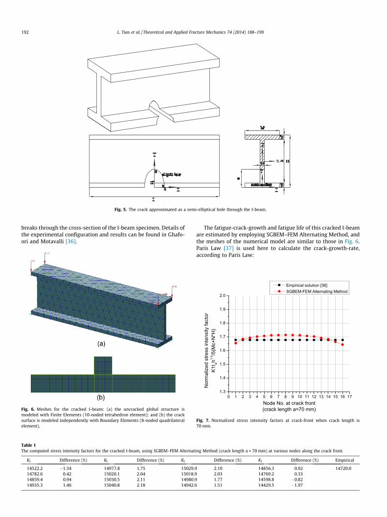
Fig. 5. The crack approximated as a semi-elliptical hole through the I-beam.
192 L. Tian et al. / Theoretical and Applied Fracture Mechanics 74 (2014) 188–199
breaks through the cross-section of the I-beam specimen. Details ofthe experimental configuration and results can be found in Ghafo-ori and Motavalli [36].
Fig. 6. Meshes for the cracked I-beam: (a) the uncracked global structure ismodeled with Finite Elements (10-noded tetrahedron element); and (b) the cracksurface is modeled independently with Boundary Elements (8-noded quadrilateralelement).
Table 1The computed stress intensity factors for the cracked I-beam, using SGBEM–FEM Alternat
KI Difference (%) KI Difference (%) KI
14522.2 �1.34 14977.8 1.75 15029.914782.6 0.42 15020.1 2.04 15018.914859.4 0.94 15030.5 2.11 14980.914935.3 1.46 15040.8 2.18 14942.
The fatigue-crack-growth and fatigue life of this cracked I-beamare estimated by employing SGBEM–FEM Alternating Method, andthe meshes of the numerical model are similar to those in Fig. 6.Paris Law [37] is used here to calculate the crack-growth-rate,according to Paris Law:
ing Method (crack length a = 70 mm) at various nodes along the crack front.
Difference (%) KI Difference (%) Empirical
2.10 14856.3 0.92 14720.02.03 14769.2 0.331.77 14598.8 �0.82
6 1.51 14429.5 �1.97
Fig. 7. Normalized stress intensity factors at crack-front when crack length is70 mm.
L. Tian et al. / Theoretical and Applied Fracture Mechanics 74 (2014) 188–199 193
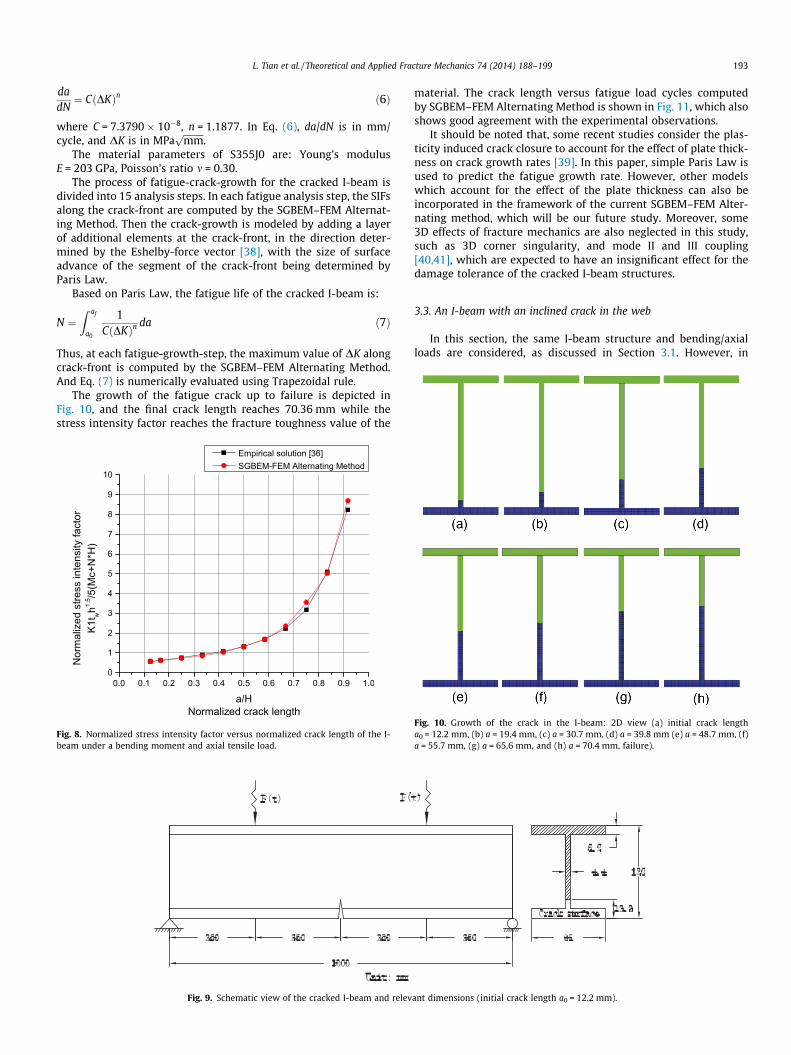
dadN¼ C DKð Þn ð6Þ
where C = 7.3790 � 10�8, n = 1.1877. In Eq. (6), da/dN is in mm/cycle, and DK is in MPa
ffiffiffiffiffiffiffiffiffimmp
.The material parameters of S355J0 are: Young’s modulus
E = 203 GPa, Poisson’s ratio m = 0.30.The process of fatigue-crack-growth for the cracked I-beam is
divided into 15 analysis steps. In each fatigue analysis step, the SIFsalong the crack-front are computed by the SGBEM–FEM Alternat-ing Method. Then the crack-growth is modeled by adding a layerof additional elements at the crack-front, in the direction deter-mined by the Eshelby-force vector [38], with the size of surfaceadvance of the segment of the crack-front being determined byParis Law.
Based on Paris Law, the fatigue life of the cracked I-beam is:
N ¼Z af
a0
1C DKð Þn
da ð7Þ
Thus, at each fatigue-growth-step, the maximum value of DK alongcrack-front is computed by the SGBEM–FEM Alternating Method.And Eq. (7) is numerically evaluated using Trapezoidal rule.
The growth of the fatigue crack up to failure is depicted inFig. 10, and the final crack length reaches 70.36 mm while thestress intensity factor reaches the fracture toughness value of the
Fig. 8. Normalized stress intensity factor versus normalized crack length of the I-beam under a bending moment and axial tensile load.
Fig. 9. Schematic view of the cracked I-beam and relev
material. The crack length versus fatigue load cycles computedby SGBEM–FEM Alternating Method is shown in Fig. 11, which alsoshows good agreement with the experimental observations.
It should be noted that, some recent studies consider the plas-ticity induced crack closure to account for the effect of plate thick-ness on crack growth rates [39]. In this paper, simple Paris Law isused to predict the fatigue growth rate. However, other modelswhich account for the effect of the plate thickness can also beincorporated in the framework of the current SGBEM–FEM Alter-nating method, which will be our future study. Moreover, some3D effects of fracture mechanics are also neglected in this study,such as 3D corner singularity, and mode II and III coupling[40,41], which are expected to have an insignificant effect for thedamage tolerance of the cracked I-beam structures.
3.3. An I-beam with an inclined crack in the web
In this section, the same I-beam structure and bending/axialloads are considered, as discussed in Section 3.1. However, in
ant dimensions (initial crack length a0 = 12.2 mm).
Fig. 10. Growth of the crack in the I-beam: 2D view (a) initial crack lengtha0 = 12.2 mm, (b) a = 19.4 mm, (c) a = 30.7 mm, (d) a = 39.8 mm (e) a = 48.7 mm, (f)a = 55.7 mm, (g) a = 65.6 mm, and (h) a = 70.4 mm, failure).

100 101 102 103 104 105 10610
20
30
40
50
60
70
80
log(N) (cycles)
Cra
ck le
ngth
a (m
m)
Experimental result [36]Present numerical result
Fig. 11. Crack length versus number of load cycles for the I-beam (stress ratioR = 0.1).
Fig. 12. A schematic view of the crack for the I-beam with different lengths andinclination angles.
Table 2The configurations of the cracks for the I-beam and their labels.
Crack length a (mm) Inclination h (�)
30 45 60
40 C1 C2 C360 C4 C5 C680 C7 C8 C9
Table 3The computed stress intensity factors for the cracked I-beams with different crackconfigurations.
Crack label KI KII KIII
C1 3138.29 2149.56 30.56C2 4541.45 2093.26 52.54C3 5959.65 1745.98 39.37C4 3381.71 2326.39 77.79C5 5530.70 2522.13 89.84C6 8139.04 2353.40 9.02C7 3312.22 2747.07 325.61C8 7025.69 3282.32 137.35C9 12258.59 3482.24 75.59
194 L. Tian et al. / Theoretical and Applied Fracture Mechanics 74 (2014) 188–199
current case, a mixed-mode inclined crack is considered instead ofa mode-I vertical crack. Fig. 12 shows a schematic view of the ini-tial cracks with different lengths and inclination angles, where a
Fig. 13. Normalized stress intensity factors versus crack inclination angle (initialcrack length a0 = 40 mm).
Fig. 14. Normalized stress intensity factors versus crack inclination angle (initialcrack length a0 = 60 mm).
Fig. 15. Normalized stress intensity factors versus crack inclination angle (initialcrack length a0 = 80 mm).

L. Tian et al. / Theoretical and Applied Fracture Mechanics 74 (2014) 188–199 195
represents the crack length, and h represents the inclination angle.The detailed initial lengths and inclination angles of each crack arelisted in Table 2.
Fig. 16. Fatigue crack length versus number of load cycles for the I-beam (initialcrack length a0 = 40 mm).
Fig. 17. Growth of the inclined crack in the I-beam: 3D view, (a) initial crack length a0 = 4and (e) 2D view, the final crack in the I-beam.
The computed SIFs for each case by SGBEM–FEM AlternatingMethod are listed in Table 3, and the normalized SIFs versus crackinclination angles for different initial crack lengths are plotted inFigs. 13–15. It is shown that the stress intensity factors vary signif-icantly with respect to the crack inclination angle: when the crackinclination angle is rather small, both mode I and mode II SIFs arecomparable, but mode I SIFs increase rapidly while crack inclina-tion angle is increased. Since analytical or empirical SIFs for thesemixed-mode cracks are not available in the open literature, SIFsobtained by SGBEM–FEM Alternating Method can be used asbenchmarks in the future studies of cracked I-beams by otherinvestigators.
Fatigue-crack-growth of the cracked I-beam with initial cracklength a0 = 40 mm and crack inclination angle h = 45� is also simu-lated using SGBEM–FEM Alternating Method. Paris Law is usedhere with material constants C = 7.3790 � 10�8, n = 1.1877, andthe stress ratio is R = 0.1. The fatigue life and fatigue-crack-growthpaths are shown in Figs. 16 and 17.
3.4. An I-beam with a slant edge crack in the flange subjected totorsional forces
In this section, a cantilever I-beam with a slant through-the-thickness edge crack on its bottom flange is considered. The I-beam
0 mm, (b) crack length a = 51.78 mm, (c) a = 69.40 mm, (d) final crack, a = 94.89 mm,

Fig. 18. The I-beam with slant edge crack: geometry and load.
Table 4The difference in the computed stress intensity factors between different meshes(a = 10 mm).
Mesh KI KII Keff
Fig. 13(a) and (c) 10796.11 5964.51 14119.99Fig. 13(a) and (d) 10618.79 5927.99 13938.81Fig. 13(b) and (c) 11098.95 6031.65 14433.79Fig. 13(b) and (d) 10907.66 6004.52 14248.38
Fig. 19. Meshes for the I-beam with a slant edge crack: the uncracked global structureelement, (b) dense mesh with 2660 10-noded tetrahedron element; the crack surface isquadrilateral elements, and (d) dense mesh with 100 8-noded quadrilateral elements.
196 L. Tian et al. / Theoretical and Applied Fracture Mechanics 74 (2014) 188–199
is subjected to shear forces with opposite directions on the crosssection of its top and bottom flange, which leads to a resultant tor-sional moment. A slant edge crack (a = 45�) which cuts through thebottom flange has been introduced to the I-beam. Material proper-ties are (Young’s modulus E = 206.8 GPa; Poisson’s ratio m = 0.29).All the relevant dimensions are shown in Fig. 18.
is modeled with Finite Elements, (a) coarse mesh with 544 10-noded tetrahedronmodeled independently with Boundary Elements, (c) coarse mesh with 25 8-noded
Fig. 20. I-beam with a slant edge crack in the flange: normalized stress intensityfactors versus crack length.

L. Tian et al. / Theoretical and Applied Fracture Mechanics 74 (2014) 188–199 197
The SGBEM–FEM Alternating Method is employed here to solvethis problem, with two different FEM meshes for the uncrackedglobal structure, as well as two different BEM meshes for the cracksurface. The computed SIFs are given in Table 4, demonstratingthat the computed SIFs are insensitive to FEM and SGBEM meshes.Moreover, as shown in Fig. 19, the meshes for the SGBEM–FEMAlternating Method consist of up to a few thousands of finite ele-ments and a few hundreds boundary elements. On the other hand,for pure finite-element-based methods, it is typical to use morethan a million degrees of freedom to model a cracked 3D complexstructure. Thus the current SGBEM–FEM Alternating Methodgreatly reduces the burden of computation as well as the
Fig. 21. Crack length versus number of load cycles for the I-beam (initial cracklength a0 = 10 mm).
Fig. 22. Growth of the crack in the I-beam: 3D view, (a) initial crack length a0 = 10 mm, (bcrack surface, and (f) 2D view, final crack with the I-beam.
human-labor for preprocessing, compared to FEM-based numericalmethods, by several orders of magnitude.
Different crack lengths are also considered for this problem(a = 10, 20, 30, 40 mm). The computed SIFs by the SGBEM–FEMAlternating Method are shown in Fig. 20, which clearly indicatesthat it is a mixed-mode crack for which mode I and mode II SIFsare dominant compared to the mode III SIF.
Fatigue-crack-growth analyses of the I-beam with initialcrack length a0 = 10 mm and a0 = 40 mm are simulated usingSGBEM–FEM Alternating Method. Paris Law is used here withC = 3.6 � 10�10, n = 3.0.
) crack length a = 41.75 mm, (c) a = 64.41 mm, (d) final crack, a = 82.90 mm, (e) final
Fig. 23. Crack length versus number of load cycles for the I-beam (initial cracklength a0 = 40 mm).

Fig. 24. Growth of the crack in the I-beam: 3D view, (a) initial crack length a0 = 40 mm, (b) crack length a = 57.06 mm, (c) a = 73.61 mm, (d) final crack, a = 90.63 mm, (e) finalcrack surface, and (f) 2D view, final crack with the I-beam.
198 L. Tian et al. / Theoretical and Applied Fracture Mechanics 74 (2014) 188–199
The maximum magnitude of the cyclic load is F = 100 N/mm.And the stress ratio is R = 0.1. For the I-beam with an initial cracklength a0 = 10 mm, the fatigue life and fatigue crack paths areshown in Figs. 21 and 22; for the I-beam with an initial cracklength a0 = 40 mm, the fatigue life and fatigue crack paths areshown in Figs. 23 and 24.
4. Conclusions
In this paper, several numerical models of cracked I-beams areconsidered, for which the stress intensity factor analyses and fati-gue-crack-growth simulations under different load conditions arecarried out by employing the 3D SGBEM–FEM Alternating Method.For mode-I cracks in the I-beam, the computed SIFs by using theSGBEM–FEM Alternating Method are in very good agreement withempirical solutions, and the predicted fatigue life of cracked I-beams agrees well with experimental observations. For inclinedcracks in the web or in the flange of the I-beams, no analytical orempirical solutions are available in the literature. Thus mixed-mode SIFs of inclined web and flange cracks are presented andnon-planar fatigue growth simulations are given, as benchmarkexamples for future studies. Because very minimal efforts of pre-processing and very small computational burden are needed, thecurrent SGBEM–FEM Alternating Method is very suitable for frac-ture and fatigue analyses of 3D structures such as I-beams.
Acknowledgements
The first author gratefully acknowledges the financial supportof China Scholarship Council (Grant No. 201306260034); NationalBasic Research Program of China (973 Program: 2011CB013800);and New Century Excellent Talents Project in China (NCET-12-0415).
References
[1] S.N. Atluri, Structural Integrity and Durability, Tech Science Press, Forsyth,1997.
[2] R. Kienzler, G. Hermann, An elementary theory of defective beams, ActaMechan. 62 (1986) 37–46.
[3] S. Hermann, H. Sosa, On bars with cracks, Eng. Fract. Mechan. 24 (1986) 889–894.
[4] H. Gao, G. Hermann, On estimates of stress intensity factors for cracked beamsand pipes, J. Eng. Fract. Mechan. 41 (695/706) (1992).
[5] W.H. Müller, G. Hermann, H. Gao, Elementary strength theory of crackedbeams, Theor. Appl. Fract. Mechan. 18 (1993) 163–177.
[6] M.L. Dunn, W. Suwito, B. Hunter, Stress intensity factor for cracked I-beams,Eng. Fract. Mechan. 57 (6) (1997) 609–615.
[7] Y.J. Xie, H. Xu, P.N. Li, Crack mouth widening energy-release rate and itsapplication, Theor. Appl. Fract. Mechan. 29 (1998) 195–203.
[8] Y.J. Xie, X.H. Wang, Application of G⁄-integral on cracked structural beams, J.Constr. Steel Res. 60 (2004) 1271–1290.
[9] Y.J. Xie, X.H. Wang, Y.C. Lin, Stress intensity factors for cracked rectangularcross section thin-walled tubes, Eng. Fract. Mechan. 71 (2004) 1501–1513.
[10] Y.J. Xie, X.H. Wang, Y.Y. Wang, Stress intensity factors for crackedhomogeneous and composite multi-channel beams, Int. J. Solids Struct. 44(2007) 4830–4844.
[11] J.M. Chandra Kishen, Kumar Avinash, Finite element analysis for fracturebehavior of cracked beam–columns, Finite Elem. Anal. Des. 40 (2004) 1773–1789.
[12] T.M. Tharp, A finite element for edge-cracked beam columns, Int. J. Numer.Meth. Eng. 24 (1987) 1941–1950.
[13] P. Tong, T.H.H. Pian, S.J. Lasry, A hybrid-element approach to crack problems inplane elasticity, Int. J. Numer. Methods Eng. 7 (1973) 297–308.
[14] S.N. Atluri, A.S. Kobayashi, M. Nakagaki, An assumed displacement hybridfinite element model for linear fracture mechanics, Int. J. Fract. 11 (1975) 257–271.
[15] R.D. Henshell, K.G. Shaw, Crack tip finite elements are unnecessary, Int. J.Numer. Methods Eng. 9 (3) (1975) 495–507.
[16] Barsoum, Application of triangular quarter-point elements as crack tipelements of power law hardening material, Int. J. Fatigue 12 (3) (1976). 463-446.
[17] S.N. Atluri, Computational Methods in the Mechanics of Fracture, NorthHolland, Amsterdam, 1986 (also translated into Russian, Mir Publishers,Moscow).
[18] T. Nishioka, S.N. Atluri, Path-independent integrals, energy release rates, andgeneral solutions of near-tip fields in mixed-mode dynamic fracturemechanics, Eng. Fract. Mechan. 18 (1) (1983) 1–22.
L. Tian et al. / Theoretical and Applied Fracture Mechanics 74 (2014) 188–199 199
[19] K. Vijayakumar, S.N. Atluri, An embedded elliptical crack, in an infinite solid,subject to arbitrary crack-face tractions, ASME, J. Appl. Mechan. 103 (1) (1981)88–96.
[20] G.P. Nikishkov, J.H. Park, S.N. Atluri, SGBEM–FEM alternating method foranalyzing 3D non-planar cracks and their growth in structural components,CMES: Comput. Model. Eng. Sci. 2 (3) (2001) 401–422.
[21] Z.D. Han, S.N. Atluri, SGBEM (for Cracked Local Subdomain) – FEM (foruncracked global Structure) Alternating Method for analyzing 3D surfacecracks and their fatigue-growth, CMES: Comput. Model. Eng. Sci. 3 (6) (2002)699–716.
[22] L. Dong, S.N. Atluri, SGBEM (Using Non-hyper-singular Traction BIE), and superelements, for non-collinear fatigue-growth analyses of cracks in stiffenedpanels with composite-patch repairs, CMES: Comput. Model. Eng. Sci. 89 (5)(2012) 417–458.
[23] L.T. Dong, S.N. Atluri, SGBEM Voronoi Cells (SVCs), with embedded arbitrary-shaped inclusions, voids, and/or cracks, for micromechanical modeling ofheterogeneous materials, CMC: Comput. Mater. Continua 33 (2) (2013) 111–154.
[24] L.T. Dong, S.N. Atluri, Fracture & fatigue analyses: SGBEM–FEM or XFEM? Part1: 2D structures, CMES-Comput. Model. Eng. Sci. 90 (2) (2013) 91–146.
[25] L.T. Dong, S.N. Atluri, Fracture & fatigue analyses: SGBEM–FEM or XFEM? Part2: 3D solids, CMES-Comput. Model. Eng. Sci. 90 (5) (2013) 379–413.
[26] F.J. Rizzo, An integral equation approach to boundary value problems ofclassical elastostatics, Quart. Appl. Math 25 (1) (1967) 83–95.
[27] H.K. Hong, J.T. Chen, Derivations of integral equations of elasticity, J. Eng.Mechan. 114 (6) (1988) 1028–1044.
[28] A. Frangi, G. Novati, Symmetric BE method in two-dimensional elasticity:evaluation of double integrals for curved elements, Computat. Mechan. 19 (2)(1996) 58–68.
[29] M. Bonnet, G. Maier, C. Polizzotto, Symmetric Galerkin boundary elementmethods, Appl. Mechan. Rev. 51 (1998) 669–704.
[30] S. Li, M.E. Mear, L. Xiao, Symmetric weak form integral equation method forthree-dimensional fracture analysis, Comput. Methods Appl. Mechan. Eng. 151(1998) 435–459.
[31] A. Frangi, G. Novati, R. Springhetti, M. Rovizzi, 3D fracture analysis by thesymmetric Galerk in BEM, Computat. Mechan. 28 (2002) 220–232.
[32] Z.D. Han, S.N. Atluri, On simple formulations of weakly-singular traction &displacement BIE, and their solutions through Petrov-Galerkin approaches,CMES: Comput. Model. Eng. Sci. 4 (1) (2003) 5–20.
[33] Z.D. Han, S.N. Atluri, A systematic approach for the development of weakly-singular BIEs, CMES: Comput. Model. Eng. Sci. 21 (1) (2007) 41–52.
[34] H. Okada, H. Rajiyah, S.N. Atluri, A novel displacement gradient boundaryelement method for elastic stress analysis with high accuracy, J. Appl. Mechan.55 (1988) 786–794.
[35] H. Okada, H. Rajiyah, S.N. Atluri, Non-hyper-singular integral representationsfor velocity (displacement) gradients in elastic/plastic solids (small or finitedeformations), Computat. Mechan. 4 (3) (1989) 165–175.
[36] E. Ghafoori, M. Motavalli, Analytical calculation of stress intensity factor ofcracked steel I-beams with experimental analysis and 3D digital imagecorrelation measurements, Eng. Fract. Mechan. 78 (18) (2011) 3226–3242.
[37] P.C. Paris, F.A. Erdogan, A critical analysis of crack propagation laws, J. BasicEng. Trans. SME, Series D 55 (1963) 528–534.
[38] J.D. Eshelby, The force on an elastic singularity, Philosophical Trans. RoyalSociety A: Mathe., Phys. Eng. Sci. 244 (877) (1951) 87–112.
[39] J. Codrington, A. Kotousov, A crack closure model of fatigue crack growth inplates of finite thickness under small-scale yielding conditions, Mechan.Mater. 41 (2) (2009) 165–173.
[40] A. Kotousov, P. Lazzarin, F. Berto, L.P. Pook, Three-dimensional stress states atcrack tip induced by shear and anti-plane loading, Eng. Fract. Mechan. 108(2013) 65–74.
[41] A. Kotousov, Effect of plate thickness on stress state at sharp notches and thestrength paradox of thick plates, Int. J. Solids Struct. 47 (14) (2010) 1916–1923.