Fracture mechanics – fundamentalslejo/m4fatiguedesign10AEfracturemech.pdf · Fracture mechanics...
23
Fracture mechanics – fundamentals Stress at a notch Stress at a crack Stress intensity factors Fracture mechanics based design
Transcript of Fracture mechanics – fundamentalslejo/m4fatiguedesign10AEfracturemech.pdf · Fracture mechanics...
Fracture mechanics – fundamentals
Stress at a notch Stress at a crack
Stress intensity factors Fracture mechanics based design
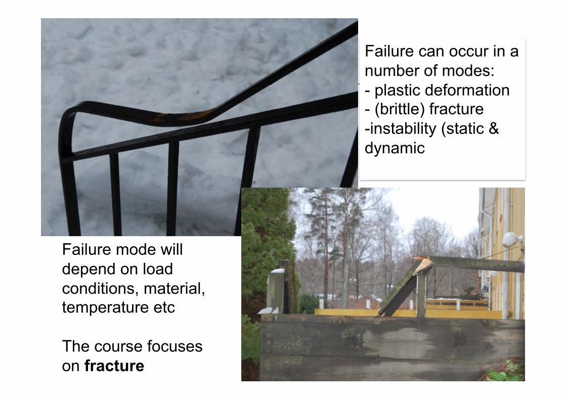
Failure modes Failure can occur in a number of modes: - plastic deformation - (brittle) fracture - instability (static & dynamic
Failure mode will depend on load conditions, material, temperature etc
The course focuses on fracture
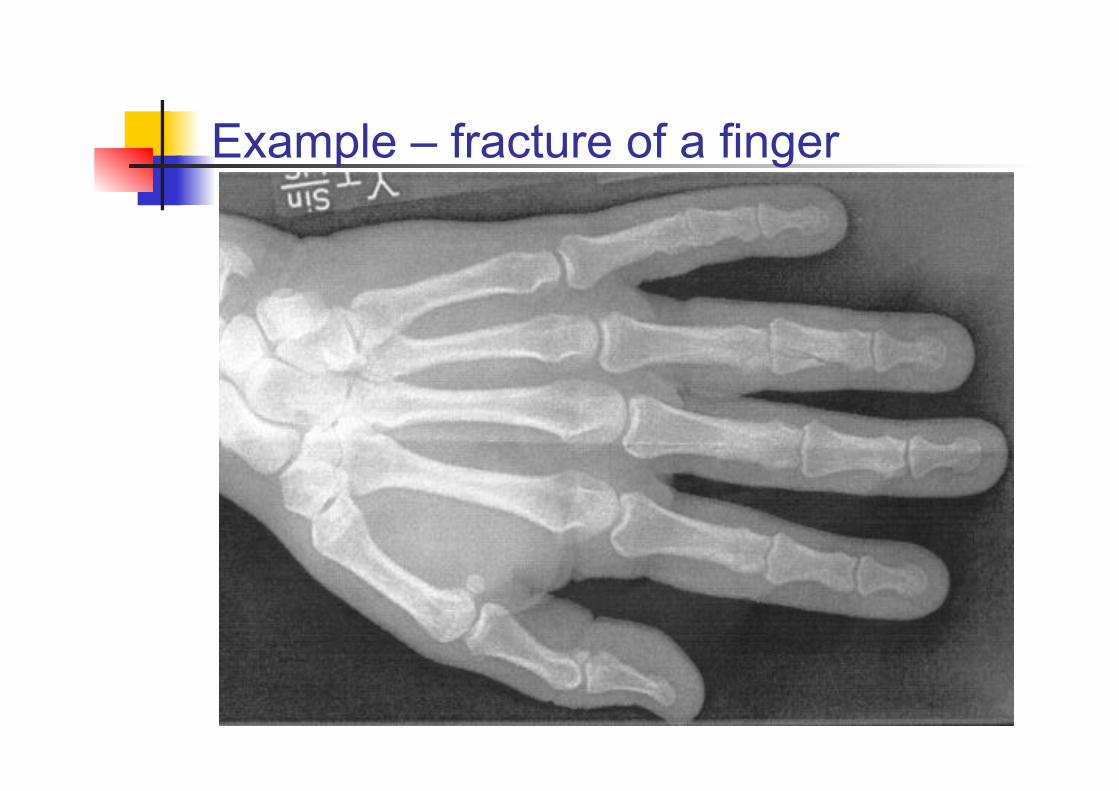
Example – fracture of a finger

Fracture – details A crack normally propagates in mode I (perpendicular to the load)
Possible reasons for branching:
- altered load direction
- anisotropy (path of least resistance)
- influence of free edge
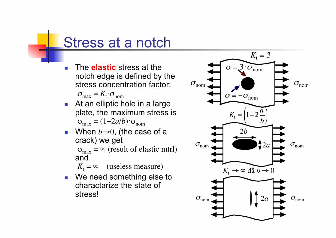
Stress at a notch!
! The elastic stress at the notch edge is defined by the stress concentration factor: !max = Kt!!nom
! At an elliptic hole in a large plate, the maximum stress is !max = (1+2a/b)!!nom
! When b"0, (the case of a crack) we get !max = ! (result of elastic mtrl)"and Kt = ! (useless measure)#
! We need something else to charactarize the state of stress!
!
"nom
!
"nom!
Kt = 3
!
" = 3#" nom
!
" = $"nom
!
Kt "# då b" 0
!
$nom
!
$nom
!
2a
!
Kt = 1+2 ab
% & '
( ) *
!
$nom
!
$nom
!
2b
!
2a
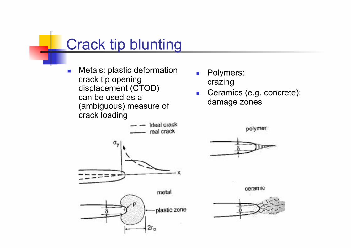
Crack tip blunting!
! Metals: plastic deformation crack tip opening displacement (CTOD) can be used as a (ambiguous) measure of crack loading
! Polymers: crazing
! Ceramics (e.g. concrete): damage zones
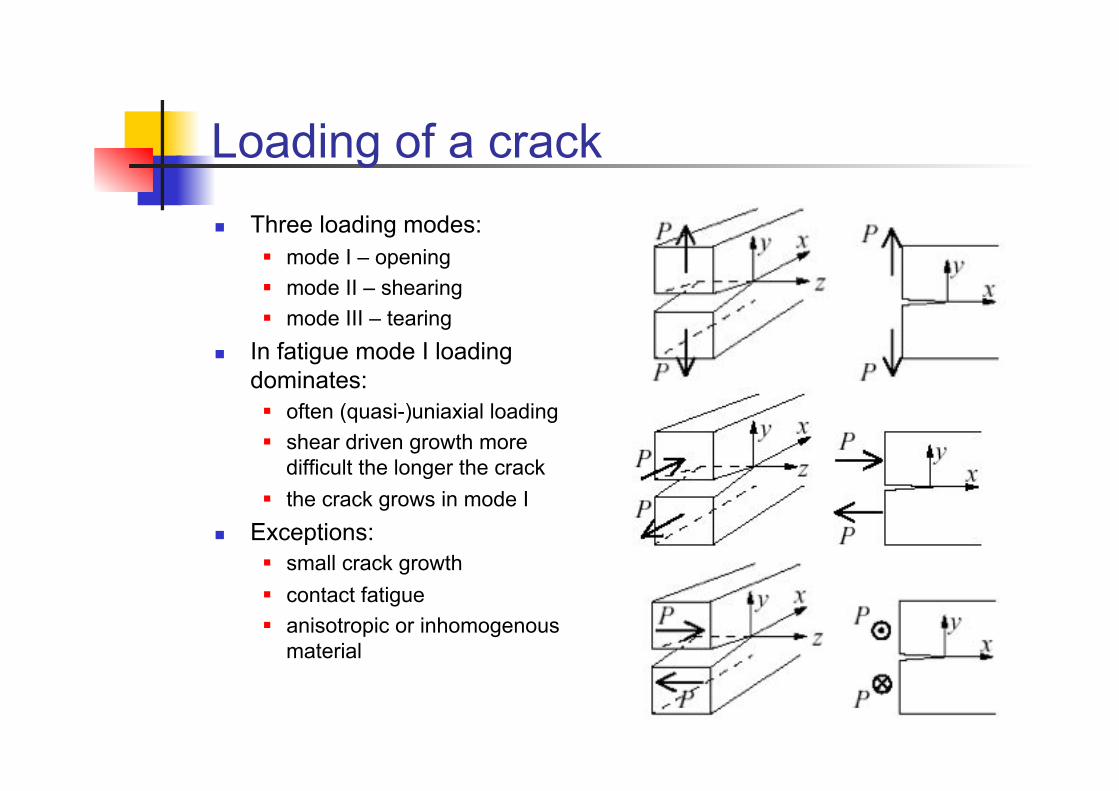
Loading of a crack ! Three loading modes:
" mode I – opening " mode II – shearing " mode III – tearing
! In fatigue mode I loading dominates: " often (quasi-)uniaxial loading " shear driven growth more
difficult the longer the crack " the crack grows in mode I
! Exceptions: " small crack growth " contact fatigue " anisotropic or inhomogenous
material
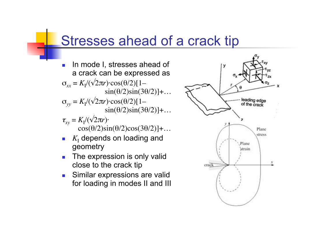
Stresses ahead of a crack tip ! In mode I, stresses ahead of
a crack can be expressed as !xx = KI/($2%r)·cos(#/2)[1–"
sin(#/2)sin(3#/2)]+…#!yy = KI/($2%r)·cos(#/2)[1–"
sin(#/2)sin(3#/2)]+…#!xy = KI/($2%r)·"
cos(#/2)sin(#/2)cos(3#/2)]+…#! KI depends on loading and
geometry ! The expression is only valid
close to the crack tip ! Similar expressions are valid
for loading in modes II and III
Stress intensity factor ! The elastic stress field at a
crack tip is characterized by KI#
! The stress intensity factor K represents “how fast the stress goes to infinity” at the crack tip
! For modes II and III we get similar results (KII and KIII)
! For the stress directly ahead of the crack tip, we get !xx = !yy = KI/$(2$x)#
! The dimension of the stress intensity factor is [N"m/m2] or [MPa"m]
! Do not confuse the stress intensity factor K with the stress concentration factor kt [–].
! Some presumptions for K to be valid are: " linear elastic material " isotropic material " ideal crack geometry " loading in one mode
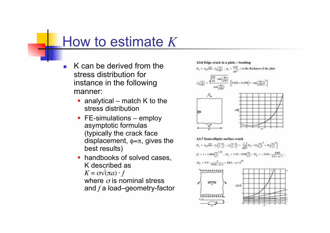
How to estimate K ! K can be derived from the
stress distribution for instance in the following manner: " analytical – match K to the
stress distribution " FE-simulations – employ
asymptotic formulas (typically the crack face displacement, %=$, gives the best results)
" handbooks of solved cases, K described as K = !$($a) · f where " is nominal stress and f a load–geometry-factor
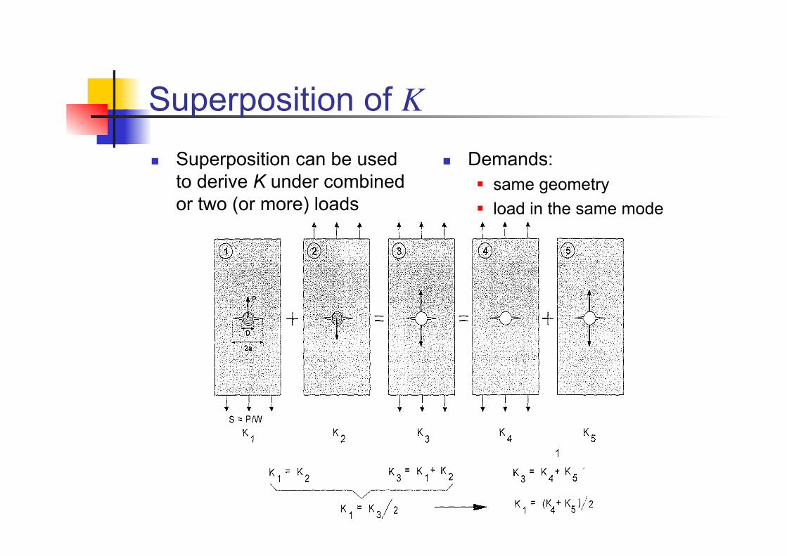
Superposition of K ! Superposition can be used
to derive K under combined or two (or more) loads
! Demands: " same geometry " load in the same mode
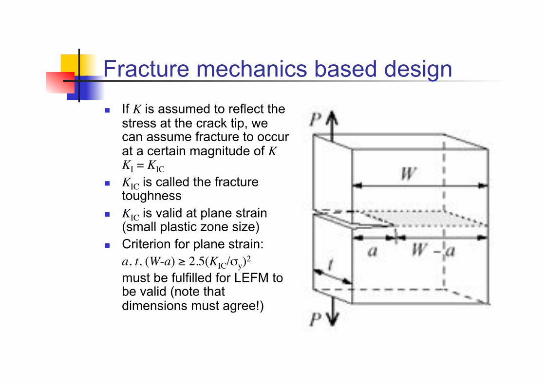
Fracture mechanics based design ! If K is assumed to reflect the
stress at the crack tip, we can assume fracture to occur at a certain magnitude of K KI = KIC
! KIC is called the fracture toughness
! KIC is valid at plane strain (small plastic zone size)
! Criterion for plane strain: a, t, (W-a) & 2.5(KIC/!y)2 "must be fulfilled for LEFM to be valid (note that dimensions must agree!)
Fracture mechanics design ! Determine allowable crack
size: " Specify location of the crack " Determine stress intensity
factor K a.f.o. {a, !,f(a)}#" from handbooks " from FE-simulations
" Find ac that yields KI = KIC " Assure that LEFM is valid
a, t, (b-a), h & 2.5(KIC/ ! y)2#
" If not, apply corrections " If true, apply safety factors
! Determine allowable stress: " Specify crack location " Specify allowable crack size " Determine stress intensity
factor K a.f.o. {a, !,f(a)}#" from handbooks " from FE-simulations
" Find ! that yields KI = KIC " Assure that LEFM is valid
a, t, (W-a), h & 2.5(KIC/ !y)2#
" If not, apply corrections " If true, apply safety factors
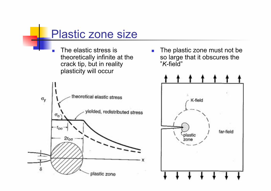
Plastic zone size ! The elastic stress is
theoretically infinite at the crack tip, but in reality plasticity will occur
! The plastic zone must not be so large that it obscures the ”K-field”
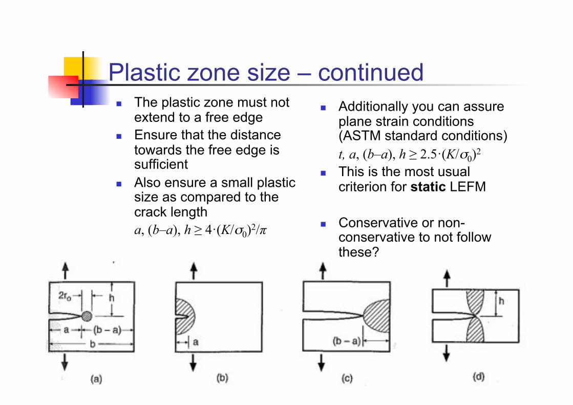
Plastic zone size – continued ! The plastic zone must not
extend to a free edge ! Ensure that the distance
towards the free edge is sufficient
! Also ensure a small plastic size as compared to the crack length a, (b–a), h ! 4"(K/"0)2/!
! Additionally you can assure plane strain conditions (ASTM standard conditions) t, a, (b–a), h ! 2.5"(K/"0)2
! This is the most usual criterion for static LEFM
! Conservative or non-conservative to not follow these?
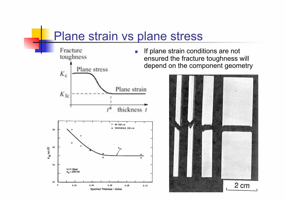
Plane strain vs plane stress ! If plane strain conditions are not
ensured the fracture toughness will depend on the component geometry
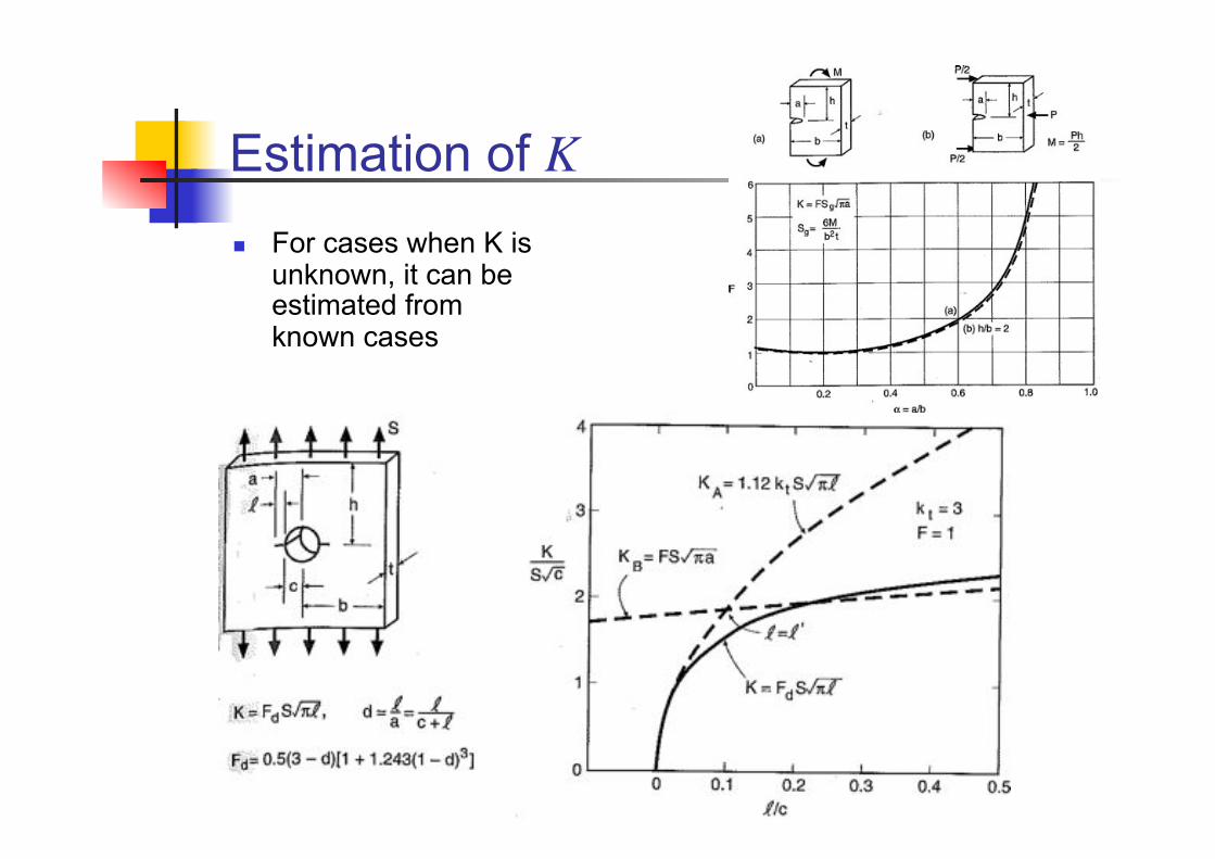
Estimation of K ! For cases when K is
unknown, it can be estimated from known cases
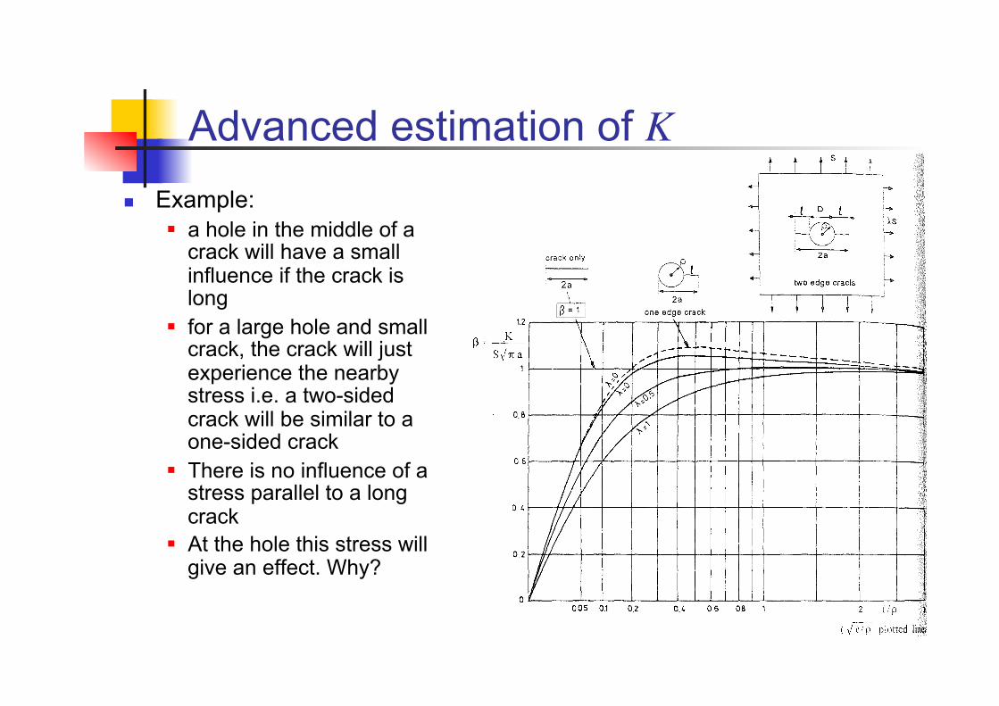
Advanced estimation of K ! Example:
" a hole in the middle of a crack will have a small influence if the crack is long
" for a large hole and small crack, the crack will just experience the nearby stress i.e. a two-sided crack will be similar to a one-sided crack
" There is no influence of a stress parallel to a long crack
" At the hole this stress will give an effect. Why?
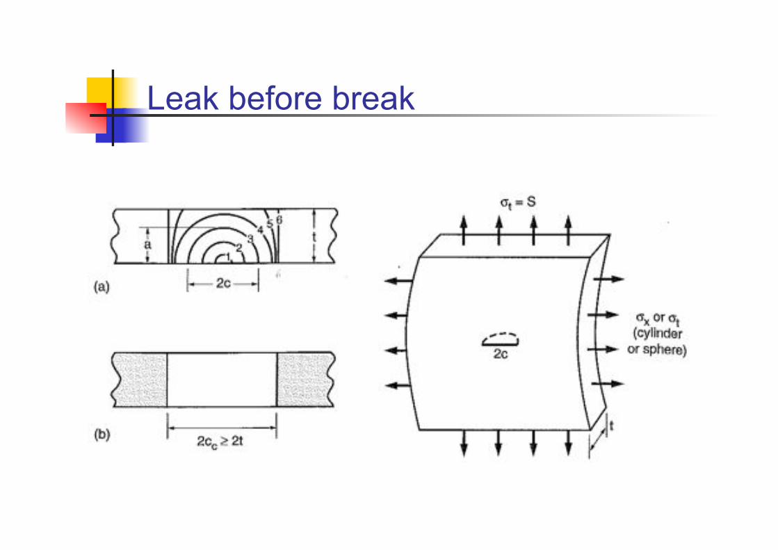
Leak before break
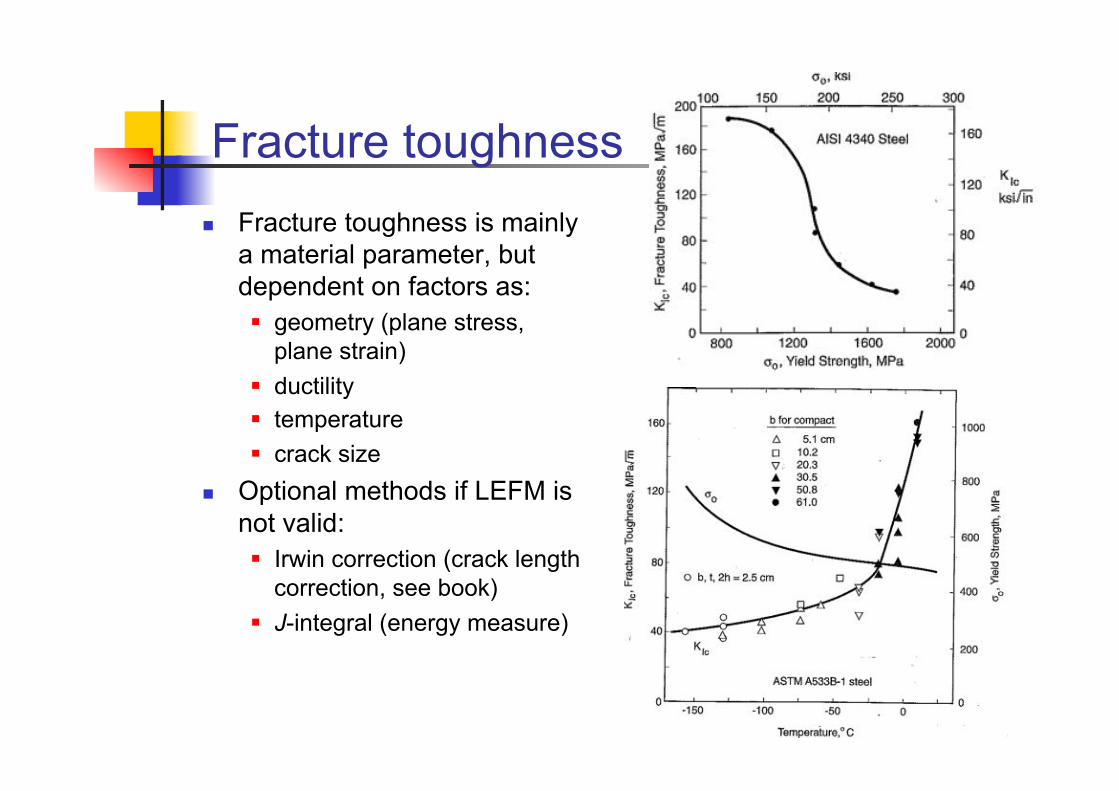
Fracture toughness ! Fracture toughness is mainly
a material parameter, but dependent on factors as: " geometry (plane stress,
plane strain) " ductility " temperature " crack size
! Optional methods if LEFM is not valid: " Irwin correction (crack length
correction, see book) " J-integral (energy measure)
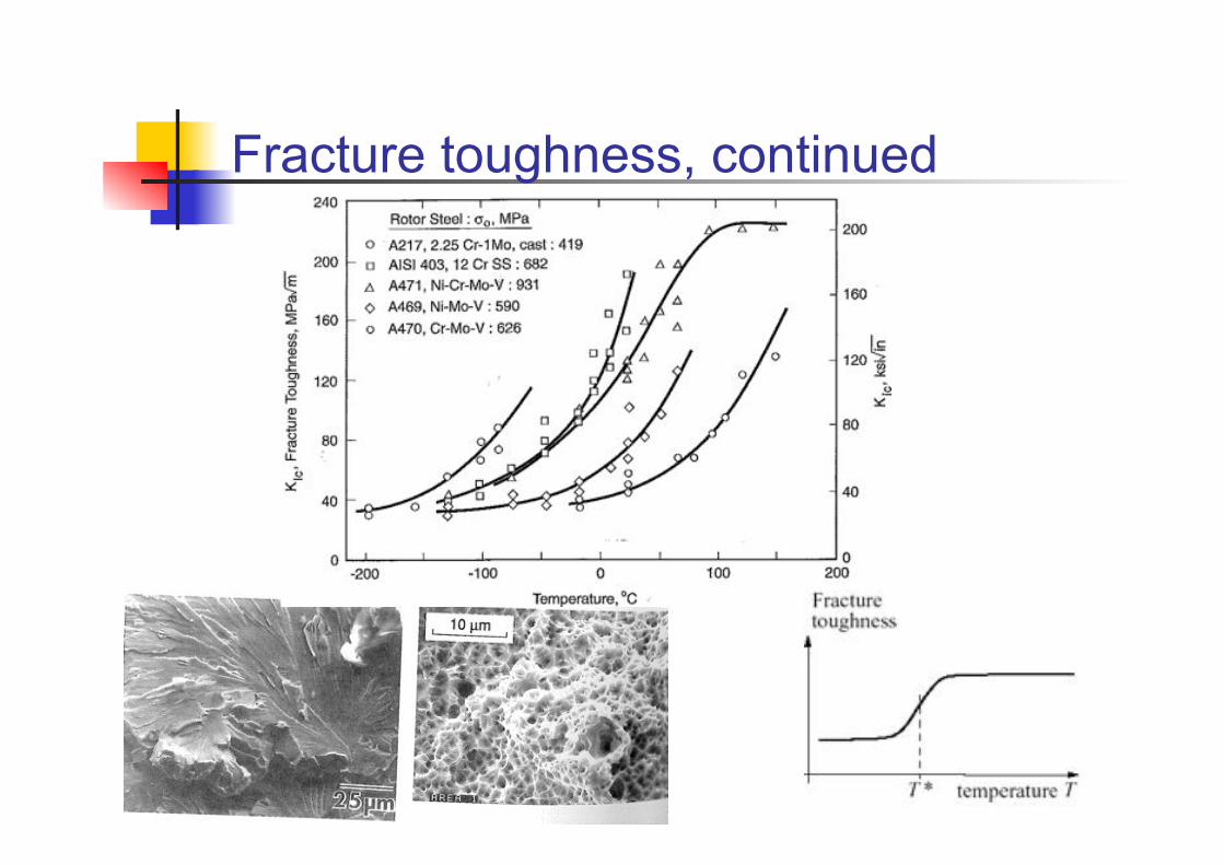
Fracture toughness, continued
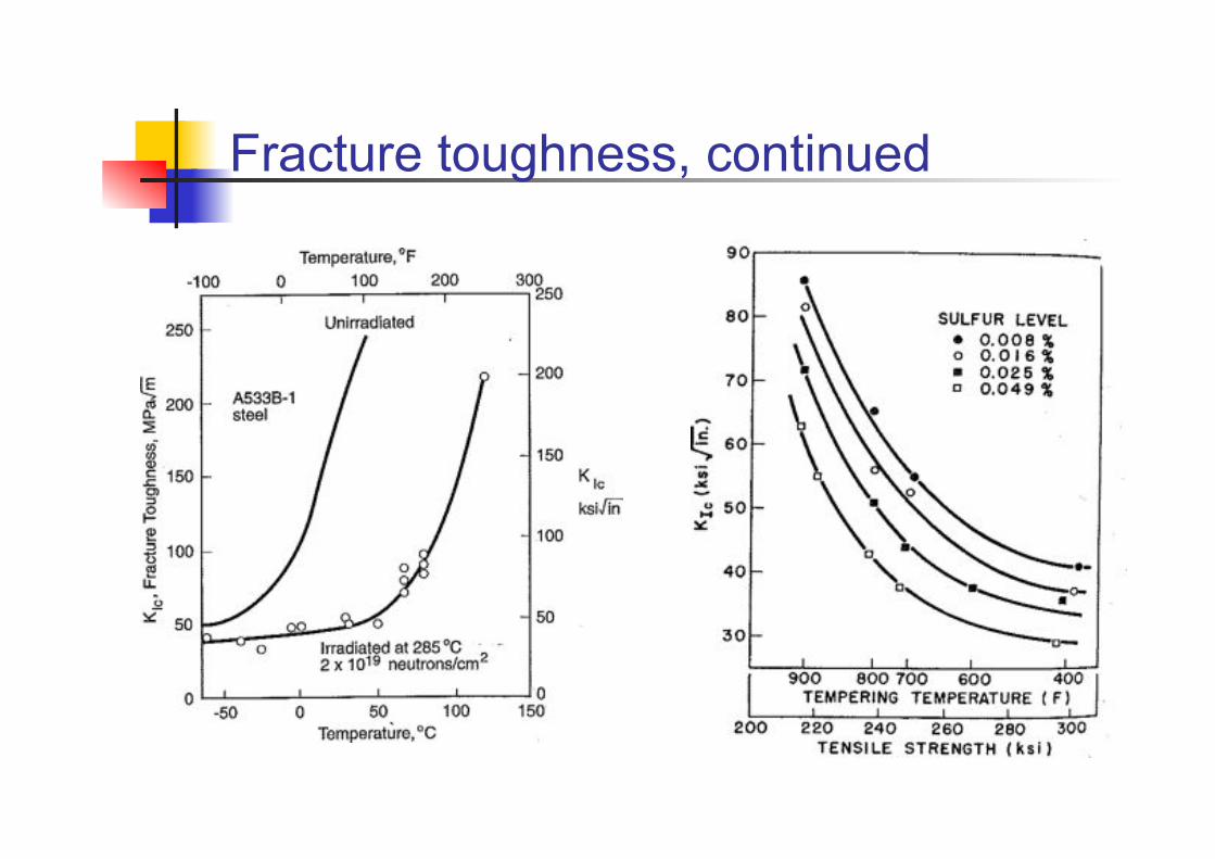
Fracture toughness, continued
Some practical comments ! LEFM in static and dynamic
loading ! Final fracture criterion (and
limits of validity) in static and dynamic loading
! Plane stress – plane strain (also in the same component)
! Environmental influence ! Elastic vs elastoplastic
modelling ! Overloads (final fracture vs
crack growth)
! FE simulations " Derivation of K
" J-integral " asymptotic formulas
" Crack modelling " mesh " crack face contacts
! Handbook solutions " Choice of standard case
" approximations " superpositions
" Derivation of “nominal stresses”
! Testing and scatter