
The Use Of Automated Backflush on the 7890A/5975A GC-MS System
10
Authors Courtney Milner and Russell Kinghorn BST International 41 Greenaway Street Bulleen, VIC 3105 Australia Matthew S. Klee 2850 Centerville Road Agilent Technologies, Inc. Wilmington, DE 19808 USA Abstract The use of column backflushing in capillary gas chro- matography has been sparingly used over the years, pri- marily due to its added complexity and demands on data system control for use in automated/routine laboratories. The potential of backflushing has been demonstrated in a gamut of applications from environmental, refining, and residues in food where high boiling point and complex matrices are commonplace. This application describes the setup, use and tricks and tips for implementing back- flushing on the 7890A/5975A GC-MS system, with the specific example of monitoring biomarkers in crude oil. Introduction Until recently, the implementation of capillary column backflush has required a cumbersome con- glomeration of parts and separate controllers. The nonintuitive combination of manual pressure regulators, timers, stand-alone valve controllers, The Use Of Automated Backflush on the 7890A/5975A GC-MS System Setup Example Using Biomarkers Application and experimentally determined GC setpoints con- spired against chromatographers with interest in attempting it. The few who were successful on a given system would rarely consider implementing backflush routinely, even if their efforts met with success the first time. Considerable improvements in implementation of backflush became available with the 6890 GC and 6890/5973 GC MSD systems [1–6]. With the release of the Agilent 7890A/5975A GC-MS system with ChemStation version E.01.00, implementation of capillary column backflush has never been easier. Full electronic control of all backflush parameters is possible in a manner never before offered in a GC-MS system. At the same time, major advancements in fluidic devices now greatly improve the mechanical aspects of implementing routine capillary column backflush. The benefits of backflush in capillary gas chromatography are myriad: • More samples/day/instrument • Better quality data • Lower operating costs • Less frequent and faster GC and MSD maintenance • Longer column life • Less chemical background When a mass spectrometer (MS) is employed, a key additional benefit is that backflushing high-boiling components from the capillary column and out of the inlet to waste (usually via a split/splitless inlet or PTV) prevents them from being deposited in the ion source. This improves detection limits for sub- Hydrocarbon Processing
Transcript of The Use Of Automated Backflush on the 7890A/5975A GC-MS System

AuthorsCourtney Milner and Russell Kinghorn
BST International
41 Greenaway Street
Bulleen, VIC 3105
Australia
Matthew S. Klee
2850 Centerville Road
Agilent Technologies, Inc.
Wilmington, DE 19808
USA
Abstract
The use of column backflushing in capillary gas chro-matography has been sparingly used over the years, pri-marily due to its added complexity and demands on datasystem control for use in automated/routine laboratories.The potential of backflushing has been demonstrated in agamut of applications from environmental, refining, andresidues in food where high boiling point and complexmatrices are commonplace. This application describesthe setup, use and tricks and tips for implementing back-flushing on the 7890A/5975A GC-MS system, with thespecific example of monitoring biomarkers in crude oil.
Introduction
Until recently, the implementation of capillarycolumn backflush has required a cumbersome con-glomeration of parts and separate controllers. Thenonintuitive combination of manual pressure regulators, timers, stand-alone valve controllers,
The Use Of Automated Backflush on the7890A/5975A GC-MS System
Setup Example Using Biomarkers
Application
and experimentally determined GC setpoints con-spired against chromatographers with interest inattempting it. The few who were successful on agiven system would rarely consider implementingbackflush routinely, even if their efforts met withsuccess the first time. Considerable improvementsin implementation of backflush became availablewith the 6890 GC and 6890/5973 GC MSD systems[1–6]. With the release of the Agilent 7890A/5975AGC-MS system with ChemStation version E.01.00,implementation of capillary column backflush hasnever been easier. Full electronic control of allbackflush parameters is possible in a mannernever before offered in a GC-MS system. At thesame time, major advancements in fluidic devicesnow greatly improve the mechanical aspects ofimplementing routine capillary column backflush.
The benefits of backflush in capillary gas chromatography are myriad:
• More samples/day/instrument
• Better quality data
• Lower operating costs
• Less frequent and faster GC and MSD maintenance
• Longer column life
• Less chemical background
When a mass spectrometer (MS) is employed, a keyadditional benefit is that backflushing high-boilingcomponents from the capillary column and out ofthe inlet to waste (usually via a split/splitless inletor PTV) prevents them from being deposited in theion source. This improves detection limits for sub-
Hydrocarbon Processing

2
sequent samples (less background) and greatlyincreases the number of samples that can be runbefore ion source cleaning is required.
As illustrated by the many prior examples (see ref-erences), backflush technology is relevant in manyareas, including the geochemical/hydrocarbonarea, wherein samples generally span a large boil-ing point range and analyses are typically long yetcontain only one or two compounds of specificinterest. Biomarker determination in crude oils issuch an example where backflush can provide sev-eral significant benefits. Analytical run times aregreatly reduced; high-boiling, less important com-ponents are removed from the system and pre-vented from reaching the mass spectrometer; andthe column is exposed to much lower final oventemperatures. In this application, backflushing ona 7890A/5875 system is presented to show the newsetup screens and increased ease of setting upbackflush conditions.
Experimental
Table 1 shows the analytical conditions used in atraditional GC-MS analysis of crude oil. The boilingpoint range of this oil sample is very wide (span-ning C4 to C50), with the target components ofinterest eluting around 30 minutes in a 74-minuteanalysis (see Results and Discussion).
connections (Figure 1). As used herein, only two ofthe ports were used, one for the column outlet(port 3) and the other for the restrictor to the MSD(port 4). The other two ports (1 and 2) wereplugged with solid wire instead of column connec-tions. Very reliable connections are a feature ofCapillary Flow Technology devices because of theuse of soft metal ferrules. Care needs to be takenwhen making these connections, but the process isvery straightforward and easily learned. The man-uals provided with the various Capillary FlowTechnology devices contain explicit instructions.
Careful consideration must be made before arestrictor internal diameter (ID) and length arechosen for a backflush application. Parameterssuch as detector type (atmospheric pressureversus vacuum), vacuum pumping capacity (forexample, diffusion pump, standard and perfor-mance turbo molecular pumps), and CapillaryFlow Device pressure and desired split ratio (ifsplitting detector effluent to multiple detectors)must all be taken into consideration. Such consid-erations are described in detail in a previous appli-cation [1].
In this example with a 5975A MSD, a deactivatedrestrictor of 1 m × 0.18 mm id (such as Agilent partnumber 160-2615-1) provided a balanced match forthis application.
Table 2 shows the analytical conditions used forthis backflush application, and Figures 2 to 7 showthe software setup screens for the 7890A/5975AGC-MS system with MSD ChemStation revisionE.01.00 software.
Table 1. Original Analytical Method Conditions
Column HP5-MS 30 m × 0.25 µm × 0.25 µm;
part number 19091S-433
Carrier gas Helium, constant flow mode; 1.2 mL/min
Split/splitless inlet 340 °C, split 30:1
Oven 50 °C (1 min) → 320 °C at 5 °C/min hold
for 20 minutes
Analysis time 74 min
Sample Crude oil in CS2, 1-µL injection
MSD Scan = 35–700 u
Samples = 22
Source = 300 °C
Quad = 150 °C
Transfer line = 320 °C
A 3-way purged splitter (Agilent part numberG3183B) Capillary Flow Technology device wasused for this application, in part to demonstrateits flexibility. The device has a purge and four
MSD In Column Out
Plugged
Plugged
4 3
2
1
Figure 1. 3-way purged splitter. The column outlet wasattached to port 3 and the MSD restrictor wasattached to port 4. Ports 1 and 2 were plugged.
3
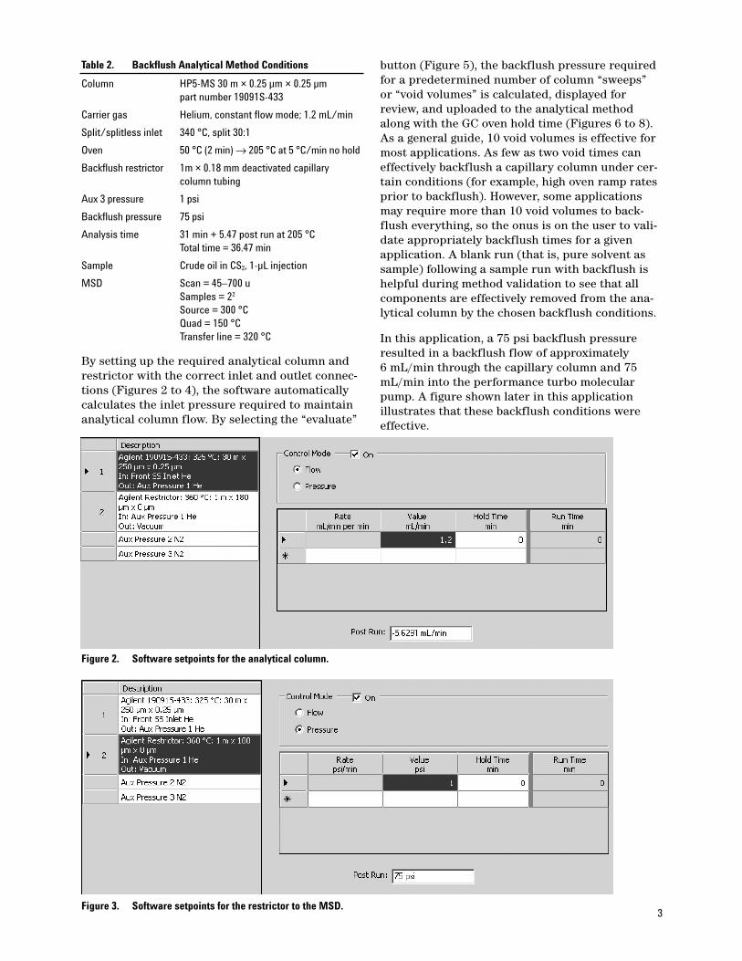
By setting up the required analytical column andrestrictor with the correct inlet and outlet connec-tions (Figures 2 to 4), the software automaticallycalculates the inlet pressure required to maintainanalytical column flow. By selecting the “evaluate”
button (Figure 5), the backflush pressure requiredfor a predetermined number of column “sweeps”or “void volumes” is calculated, displayed forreview, and uploaded to the analytical methodalong with the GC oven hold time (Figures 6 to 8).As a general guide, 10 void volumes is effective formost applications. As few as two void times caneffectively backflush a capillary column under cer-tain conditions (for example, high oven ramp ratesprior to backflush). However, some applicationsmay require more than 10 void volumes to back-flush everything, so the onus is on the user to vali-date appropriately backflush times for a givenapplication. A blank run (that is, pure solvent assample) following a sample run with backflush ishelpful during method validation to see that allcomponents are effectively removed from the ana-lytical column by the chosen backflush conditions.
In this application, a 75 psi backflush pressureresulted in a backflush flow of approximately 6 mL/min through the capillary column and 75mL/min into the performance turbo molecularpump. A figure shown later in this applicationillustrates that these backflush conditions wereeffective.
Table 2. Backflush Analytical Method Conditions
Column HP5-MS 30 m × 0.25 µm × 0.25 µm
part number 19091S-433
Carrier gas Helium, constant flow mode; 1.2 mL/min
Split/splitless inlet 340 °C, split 30:1
Oven 50 °C (2 min) → 205 °C at 5 °C/min no hold
Backflush restrictor 1m × 0.18 mm deactivated capillary
column tubing
Aux 3 pressure 1 psi
Backflush pressure 75 psi
Analysis time 31 min + 5.47 post run at 205 °C
Total time = 36.47 min
Sample Crude oil in CS2, 1-µL injection
MSD Scan = 45–700 u
Samples = 22
Source = 300 °C
Quad = 150 °C
Transfer line = 320 °C
Figure 2. Software setpoints for the analytical column.
Figure 3. Software setpoints for the restrictor to the MSD.

4
Figure 4. Column inlet and outlet conditions.
Figure 5. Interactive setup for backflush conditions in ChemStation.

5
Results and Discussion
The profile seen in Figure 9 is typical of manycrude oils with complex distribution over a largeboiling point range, with a large number of unre-solved components. Another feature is the long tail
of high-boiling components that must be elutedafter the compounds of interest. Figure 10 illus-trates the three components of interest: a series ofthree methylbenzothiophenes through an extractedion chromatogram (EIC) of m/z 198.
Figure 7. Conditions uploaded to method setpoints.
Figure 6. Conditions uploaded to method setpoints.

6
Figure 11 shows the chromatogram from anotherrun that includes a backflush immediately afterthe benzothiophenes had eluted.
In order to validate the efficacy of the backflush,a full-length analysis was undertaken with puresolvent immediately after the backflush run. It
3000000
400000
200000
600000
800000
1000000
1200000
1400000
1600000
1800000
2000000
2200000
2400000
2600000
2800000
10.00 20.00 30.00 40.00 50.00 60.00 70.00
Time
Ab
un
da
nc
e
Figure 9. Total ion chromatogram (TIC) of normal analysis. Peaks of interest (benzothiophenes) are obscuredby the high concentration of hydrocarbons.
Figure 8. Note that the post-run time has been updated automatically.

7
10.00 20.00 30.00 40.00 50.00 60.00 70.00
Time
Ab
un
da
nc
e
2000
6000
10000
14000
18000
22000
26000
30000
34000
Ion 198.00 (197.70 to 198.70
Figure 10. EIC of m/z 198 ion. The three methylbenzothiophene peaks of interest at approximately 30 minutes are easily visualized.
Time
Ab
un
da
nc
e
150000
2 4 6 8 10 12 14 16 18 20 22 24 26 28
350000
550000
750000
950000
1150000
1350000
1550000
1750000
Figure 11. TIC of backflush run; run switched to backflush mode at 31 minutes.
can be seen from Figure 12 that no residual high-boiling components remained in the capillarycolumn after the backflush from this blank solventinjection. Also, there are no residual biomarkers at m/z 198. All material (representing over 50% of thesample introduced into the column) eluting after31 minutes was effectively backflushed.
Figure 13 shows the EIC (m/z = 198) for both thenormal run and the backflushed runs, showingthat no material was lost and retention times werenot changed by implementing the backflush.

8
Time
Ion 198.00 Full Length Run
24.00 26.00 28.00 30.00 32.00 34.00 36.00 38.00
2000
6000
10000
14000
18000
22000
26000
30000
34000
Ab
un
da
nc
e
24.00 26.00 28.00 30.00 32.00 34.00 36.00 38.00
2000
6000
10000
14000
18000
22000
26000
30000
34000
Ab
un
da
nc
e
Ion 198.00 Backflush Run
Figure 13. Overlay of EIC of m/z 198 from full run and backflush run, showing the exact matching of the analytical portion of each run for the three methylbenzothiophene biomarkers.
200000
100000
5.0 10.0 15.0 20.0 25.0 30.0 35.0 40.0 45.0 50.0 55.0 60.0 65.0 70.0
400000
600000
800000
1000000
1200000
1400000
1600000
1800000
2000000
Time
Ab
un
da
nc
e
Figure 12. TIC of full run after the backflush with inset of the EIC of m/z 198.

9
4. Frank David and Matthew Klee, “Analysis of Suspected Flavor and Fragrance Allergens inCosmetics Using the 7890A GC and CapillaryColumn Backflush,” Agilent Technologies publication 5989-6460EN
5. James McCurry, “Enhancements in the Opera-tion and Precision of an ASTM D4815 Analyzerfor the Determination of Oxygenates in Gaso-line,” Agilent Technologies publication 5988-4475EN
6. Mike Szelewski, “Significant Cycle Time Reduc-tion Using the Agilent 7890A/5975A GC/MSDfor EPA Method 8270,” Agilent Technologiespublication 5989-6026EN
For More Information
For more information on our products and services,visit our Web site at www.agilent.com/chem.
Conclusions
This application demonstrates the ease with whichbackflush can be set up and executed with the7890A/5975A GC-MS system with EA 01.00 MSDChemStation. In this example, a total run timesaving of 37.5 minutes effectively halved the runtime of the original run while ensuring that theanalytical column was free from sample carryover.A confirmatory blank run following backflushingsubstantiates the efficacy of the backflush, verify-ing removal of all remaining sample components.
References1. Russell Kinghorn, Courtney Milner, and
Matthew S. Klee, “Simplified Backflush UsingAgilent 6890 GC,” Agilent Technologies publica-tion 5989-5111EN
2. Chin Kai Meng, “Improving Productivity andExtending Column Life with Backflush,” Agilent Technologies publication 5989-6018EN
3. Frank David and Matthew Klee, “GC/MS Analysis of PCBs in Waste Oil Using the Back-flush Capability of the Agilent QuickSwapAccessory,” Agilent Technologies publication5989-7601EN

Agilent shall not be liable for errors contained herein or for incidental or consequential
damages in connection with the furnishing, performance, or use of this material.
Information, descriptions, and specifications in this publication are subject to change
without notice.
© Agilent Technologies, Inc. 2008
Printed in the USA
July 11, 2008
5989-8588EN
www.agilent.com/chem


![Agilent 7890A GC Quick Reference GC/Quick... · 2016-06-13 · [Front] [Back] Identifies configuration settings. For example, when configuring a column, use these keys to iden-tify](https://static.fdocuments.net/doc/165x107/5f8389205478776f2e67a981/agilent-7890a-gc-quick-reference-gcquick-2016-06-13-front-back-identifies.jpg)

