The University of Texas at Austin, Nuclear Engineering Teaching … · 2012-11-30 · The TRIGA...
56
Department of Mechanical Engineering I THE UNIVERSITY OF TEXAS AT AUSTIN Nuclear Engineering Teaching Laboratory • Austin, Texas 78758 512-232-5370 FAX512-471-4589 http//www. me. utexas. edu/- netnl/net. html March 27, 2008 U. S. Nuclear Regulatory Commission Attn: Document Control Desk Washington D. C. 20555 Subject: Annual Report for The University of Texas at Austin, Docket 50-602 Dear Sir: Enclosed is the 2007 Annual Report for the Nuclear Engineering Teaching Laboratory at The University of Texas at Austin. This report is being submitted in accordance with Section 6.6 of the Technical Specifications. Please contact me at 512-232-5373 if you have any questions. Enclosure: 2006 Annual Report cc: A. Adams, DRIP/RTR Project Manager CF#5-30
Transcript of The University of Texas at Austin, Nuclear Engineering Teaching … · 2012-11-30 · The TRIGA...

Department of Mechanical Engineering
I THE UNIVERSITY OF TEXAS AT AUSTIN
Nuclear Engineering Teaching Laboratory • Austin, Texas 78758
512-232-5370 FAX512-471-4589 http//www. me. utexas. edu/- netnl/net. html
March 27, 2008
U. S. Nuclear Regulatory CommissionAttn: Document Control DeskWashington D. C. 20555
Subject: Annual Report for The University of Texas at Austin, Docket 50-602
Dear Sir:
Enclosed is the 2007 Annual Report for the Nuclear Engineering Teaching Laboratory at The
University of Texas at Austin. This report is being submitted in accordance with Section 6.6 of
the Technical Specifications.
Please contact me at 512-232-5373 if you have any questions.
Enclosure: 2006 Annual Report
cc: A. Adams, DRIP/RTR Project ManagerCF#5-30

The University of Texas at Austin
Nuclear Engineering TeachingLaboratory
2007
Annual Report
NRC Docket 50-602
DOE Contract No. DE-AC07-ER03919

2007 NETL Annual Report
ii

2007 NETL Annual ReportTables of Contents iiExecutive Summary iiiForward iv
1.0 Nuclear Engineering Teaching Laboratory 1-1
1.1 Introduction 1-1Purpose of the ReportAvailability of the FacilityOperating RegulationsNETL History
1.2 NETL Building 1-4J.J. Pickle Research CampusNETL Building DescriptionLaboratories, Equipment
1.3 UT-TRIGA Mark II Research Reactor 1-7Reactor DescriptionExperiment FacilitiesBeam Port Facilities
1.4 Nuclear Engineering Academic Program 1-12
1.5 NETL Divisions 1-13Operations and MaintenanceLaboratory OperationsHealth Physics
2.0 Annual Progress Report 2-1
2.1 Faculty, Staff, and Students 2-12.2 Education and Training Activities 2-82.3 Research and Development Projects 2-92.4 Publications, Reports, and Papers 2-11
3.0 Facility Operating Summaries 3-1
3.1 Operating Experience 3-13.2 Reactor Shutdowns 3-13.3 Utilization 3-43.4 Maintenance 3-43.5 Facility Changes 3-43.6 Laboratory Inspections 3-53.7 Radiation Exposures 3-83.8 Radiation Surveys 3-93.9 Radioactive Effluents, Radioactive Waste 3-14
iii

2007 NETL Annual ReportEXECUTIVE SUMMARY
The Nuclear Engineering Teaching Laboratory (NETL) facility continues to support the
academic and research missions of The University of Texas but has begun to provide these
support functions to other institutions. The NETL and NRE programs received an Innovations in
Nuclear Infrastructure and Education (INIE) grant from the DOE in June of 2002. The INIE
Southwest Consortium is a partnership between the University of Texas, Texas A&M University,
the University of New Mexico and the Sandia National Laboratories. The funds from this
program have permitted significant upgrades of the experimental facilities and research
programs. The environmental research and analysis services performed by the NETL during this
past year supported the Sandia National Laboratories, Los Alamos National Laboratory, Oak
Ridge National Laboratory, the Canadian government, the University of Texas-Pan American,
the University of Texas Medical Branch at Dallas, Idaho State University, the University of
Illinois, Texas A&M University and the State of Texas.
iv
2007 NETL Annual Report
FORWARD
The mission of the Nuclear Engineering Teaching Laboratory at The University of
Texas at Austin is to:
* Educate the next generation of leaders in nuclear science and engineering.* Conduct leading research at the forefront of the international nuclear community." Apply nuclear technology for solving multidisciplinary problems.
" Provide service to the citizens of Texas, the U.S., and the international community.
This objective is achieved by carrying out a well-balanced program of education, research,
and service. The NETL research reactor supports hands-on education in reactor physics and
nuclear science. In addition, students in non-nuclear fields such as physics, chemistry, and
biology use the reactor in laboratory course work. It may also be used in education
programs for nuclear power plant personnel, secondary schools students and teachers, and
the general public.
The NETL research reactor benefits a wide range of on-campus and off-campus
users, including academic, medical, industrial, and government organizations. The principal
services offered by our reactor involve material irradiation, trace element detection, material
analysis, and radiographic analysis of objects and processes. Such services establish
beneficial links to off-campus users, expose faculty and students to multidisiplinary research
and commercial applications of nuclear science, and earn revenues to help support Nuclear
Engineering activities.
Steven BiegalskiDirectorNuclear Engineering Teaching Laboratory
v

Chapter 1

2007 NETL Annual Report
1.0 NUCLEAR ENGINEERING TEACHING LABORATORY
1.1 Introduction
Purpose of the Report
The Nuclear Engineering Teaching Laboratory (NETL) at The University of Texas at
Austin prepares an annual report of program activities to comply with requirements of the
nuclear reactor license and the Department of Energy's fuel assistance program. Information in
this report provides an introduction to the education, research, and service programs of the
NETL. A TRIGA nuclear reactor is the major experimental facility at the Laboratory. The
reactor operates at power levels up to 1000 kilowatts or with pulse reactivity insertions up to
2.2% Ak/k.
Figure 1-1 NETL - Nuclear Engineering Teaching Laboratory
The annual report satisfys requirements of the University Fuel Assistance Program, U.S.
Department of Energy (DOE) [contract number DE-AC07-ER03919, Amendment A015; C85-
110742 Task Order 2, Mod. 1], and the licensing agency, the U.S. Nuclear Regulatory
1-1

2007 NETL Annual Report
Commission (NRC) [docket number 50-602]. This annual report covers the period from January
1, 2007 to December 31, 2007.
1-2

2007 NETL Annual Report
Availability of the Facility
The NETL facility serves a multipurpose role. The use of NETL by faculty, staff, and
students in the College of Engineering is the Laboratory's primary function. In addition, the
development and application of nuclear methods are done to assist researchers from other
universities, industry, and government. NETL provides services to industry, government and
other laboratories for the testing and evaluation of materials. Public education through tours and
demonstrations is also a routine function of the laboratory operation.
- Operating Regulations
Licensing of activities at NETL involve both Federal and State agencies. The nuclear
reactor is subject to the terms and specifications of Nuclear Regulatory Commission (NRC)
License R-129, a class 104c research reactor license. Another NRC license, SNM-180, for
special nuclear material, provides for the use of a subcritical assembly with neutron sources.
Both licenses are responsibilities of the NETL. For general use of radioisotopes the university
maintains a broad license with the State of Texas, L00485. Functions of the broad license are the
responsibility of the University Office of Environmental Health and Safety.
NETL History
Development of the nuclear engineering program was an effort of both physics and
engineering faculty during the late 1950's and early 1960's. The program became part of the
Mechanical Engineering Department where it remains to this day. The program installed,
operated, and dismantled a TRIGA nuclear reactor at a site on the main campus in the
engineering building, Taylor Hall. Initial criticality for the first UT reactor was August 1963
with the final operation in April 1988. Power at startup was 10 kilowatts (1963) with one power
upgrade to 250 kilowatts (1968). The total burnup during a 25 year period from 1963 to 1988
was 26.1 megawatt-days. Pulse capability of the reactor was 1.4% Ak/k with a total of 476
pulses during the operating history. Dismantling and decommissioning of the facility were
completed in December 1992.
Planning for a new facility, which led to the shutdown of the campus facility, began in
October 1983, with construction commencing in December 1986 and continuing until May 1989.
The final license was issued in January 1992, and initial criticality occurred on March 12, 1992.
1-3

2007 NETL Annual Report
The new facility, including support laboratories, administrative offices, and the reactor is the
central location for all NETL activities.
Land use in the area of the NETL site began as an industrial site during the 1940's.
Following the 1950's, lease agreements between the University and the Federal government led
to the creation of the Balcones Research Center. In the 1990's, the University became owner of
the site, and in 1994 the site name was changed to the J.J. Pickle Research Campus to honor
retired U.S. Congressman James "Jake" Pickle.
1-4
2007 NETL Annual Report
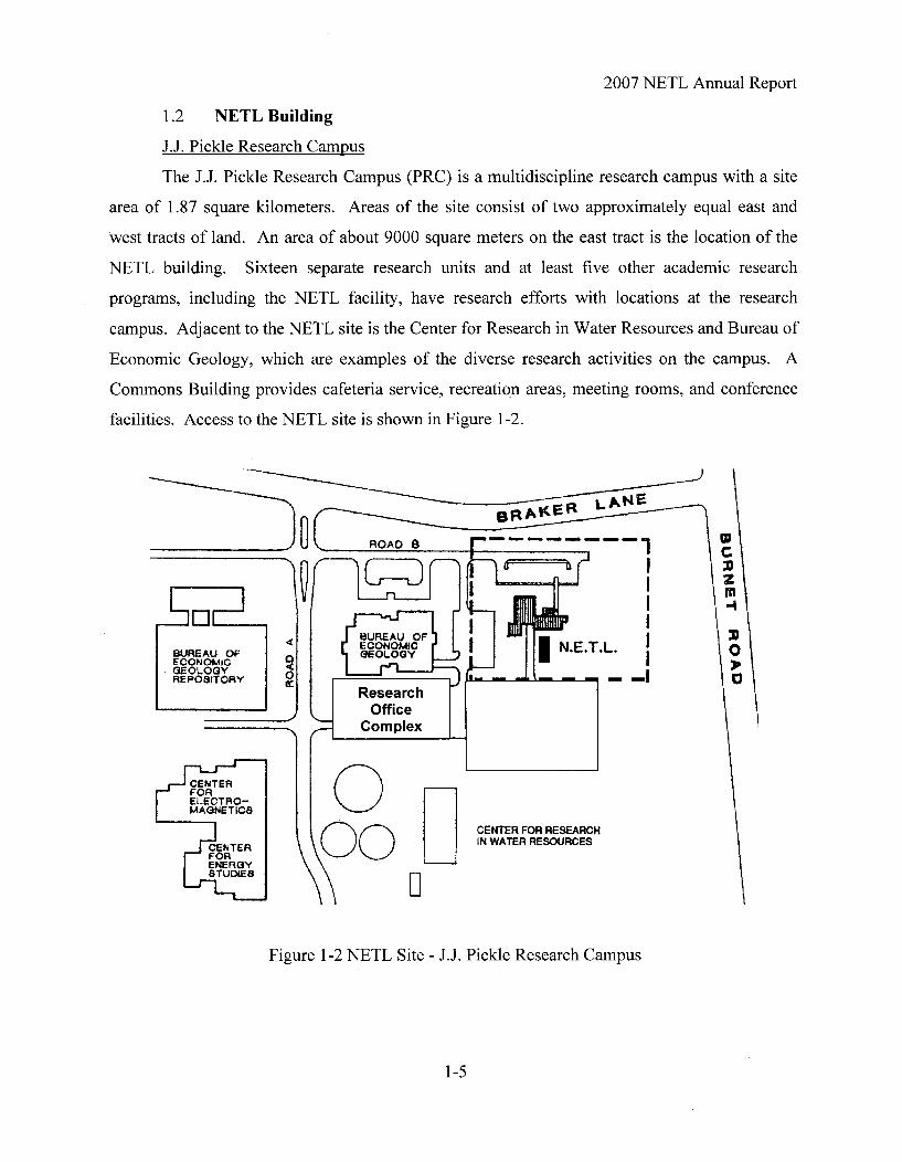
1.2 NETL Building
J.J. Pickle Research Campus
The J.J. Pickle Research Campus (PRC) is a multidiscipline research campus with a site
area of 1.87 square kilometers. Areas of the site consist of two approximately equal east and
west tracts of land. An area of about 9000 square meters on the east tract is the location of the
NETL building. Sixteen separate research units and at least five other academic research
programs, including the NETL facility, have research efforts with locations at the research
campus. Adjacent to the NETL site is the Center for Research in Water Resources and Bureau of
Economic Geology, which are examples of the diverse research activities on the campus. A
Commons Building provides cafeteria service, recreation areas, meeting rooms, and conference
facilities. Access to the NETL site is shown in Figure 1-2.
3 tp
tFA1 LKN
Figure 1-2 NETL Site - J.J. Pickle Research Campus
1-5

2007 NETL Annual Report
NETL Building Description
The NETL building is a 1950 sq meter (21,000 sq ft), facility with laboratory and office
spaces. Building areas consist of two primary laboratories of 330 sq m (3600 sq ft) and 80 sq m
(900 sq ft), eight support laboratories (217 sq m, 2340 sq ft), and six supplemental areas (130 sq
m, 1430 sq ft). Conference and office space is allocated to 12 rooms totaling 244 sq m (2570 sq
ft). One of the primary laboratories contains the TRIGA reactor pool, biological shield structure,
and the neutron beam experiment areas. A second primary laboratory consists of 1.3 meter (4.25
ft) thick walls for use as a general purpose radiation experiment facility. Other areas of the
building include support shops, instrument laboratories, measurement laboratories, and material
handling laboratories.
Laboratories, Equipment
The NETL facility makes available several types of radiation facilities and an array of
radiation detection equipment. In addition to the reactor, facilities include a subcritical
assembly, a gamma irradiator, various radioisotope sources, and several radiation producing
machines.
Neutron sources of plutonium-beryllium and califomium-252 are available. A subcritical
assembly of 20% enriched uranium in a polyethylene moderated cylinder provides an
experimental device for laboratory demonstrations of neutron multiplication and neutron flux
measurements. A full critical loading of fuel from the Manhattan College Zero Power Reactor is
currently available for subcritical experiments.
Laboratories provide locations to setup radiation experiments, test instrumentation,
prepare materials for irradiation, process radioactive samples and experiment with radiochemical
reactions.
1-6
2007 NETL Annual Report
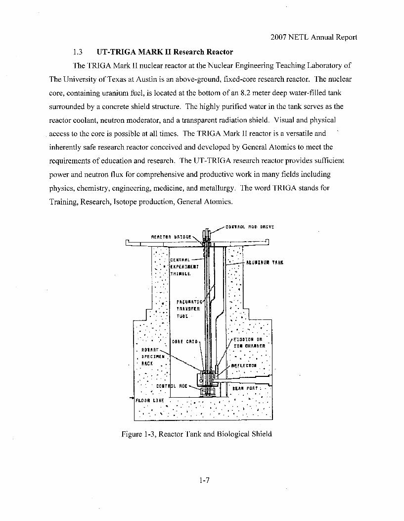
1.3 UT-TRIGA MARK II Research Reactor
The TRIGA Mark II nuclear reactor at the Nuclear Engineering Teaching Laboratory of
The University of Texas at Austin is an above-ground, fixed-core research reactor. The nuclear
core, containing uranium fuel, is located at the bottom of an 8.2 meter deep water-filled tank
surrounded by a concrete shield structure. The highly purified water in the tank serves as the
reactor coolant, neutron moderator, and a transparent radiation shield. Visual and physical
access to the core is possible at all times. The TRIGA Mark II reactor is a versatile and
inherently safe research reactor conceived and developed by General Atomics to meet the
requirements of education and research. The UT-TRIGA research reactor provides sufficient
power and neutron flux for comprehensive and productive work in many fields including
physics, chemistry, engineering, medicine, and metallurgy. The word TRIGA stands for
Training, Research, Isotope production, General Atomics.
C3KITiOL ROD DRIVE
EREL - ,..-. ,ALUMINUM TA,AKEXPERMENT.7rH IMlBL E, , I
TRA 19FER: 2 '"'
TUBE • ,:
e.. . ' •O~t C~i , /,"•' $10 ORAM
RDVARTSPECIMr~EN . .
A AcK REzFLE CTOR,
FLOO)R LINE' - "" " " " "" '
Figure 1-3, Reactor Tank and Biological Shield
1-7

2007 NETL Annual Report
Reactor Description
Reactor Operation. The UT-TRIGA research reactor can operate continuously at nominal
powers up to 1 MW, or in the pulsing mode where typical peak powers of 1500 MW can be
achieved for durations of about 10 msec. The UT-TRIGA with its digital control system
provides a unique facility for performing reactor physics experiments as well as reactor operator
training. The pulsing operation is particularly useful in the study of reactor kinetics and control.
Neutrons produced in the reactor core can be used in a wide variety of research applications
including nuclear reaction studies, neutron scattering experiments, and nuclear analytical and
irradiation services.
Special neutron facilities include a rotary specimen rack, which is located in the reactor
graphite reflector, a pneumatically operated "rabbit" transfer system, which penetrates the reactor
core, and a central thimble, which allows samples to be inserted into the peak flux region of the
core. Cylindrical voids in the concrete shield structure, called neutron beam ports, allow
neutrons to stream out away from the core. Experiments may be done inside the beam ports or
outside the concrete shield in the neutron beams.
Nuclear Core. The reactor core is an assembly of about 100 fuel elements surrounded by
an annular graphite neutron reflector. Each element consists of a fuel region capped at top and
bottom with a graphite section, all contained within a thin-walled stainless steel tube. The fuel
region is a metallic alloy of low-enriched uranium evenly distributed in zirconium hydride
(UZrH). The physical properties of the TRIGA fuel provide an inherently safe operation. Rapid
power transients to high powers are automatically suppressed without using mechanical control;
the reactor quickly returns to normal power levels. Pulse operation, which is a normal mode of
operation, is a practical demonstration of this inherent safety feature.
Reactor Reflector. The aluminum-canned graphite neutron reflector surrounding the
reactor was flooded in 2000 by the NETL staff to correct pressurization problems. The reflector
was replaced in 2004 with slight modification.
1-8

2007 NETL Annual Report
Reactor Control. The instrumentation for the UT-TRIGA research reactor is contained in
a compact microprocessor-driven control system. This advanced system provides for flexible
and efficient operation with precise power and flux control. It also allows permanent retention of
all pertinent data. The power level of the UT-TRIGA is controlled by four control rods. Three
of these rods, one regulating and two shim, are sealed stainless steel tubes containing powdered
boron carbide followed by UZrH. As these rods are withdrawn, boron (a neutron absorber)
leaves the core and UZrH (fuel) enters the core, increasing power. The fourth control rod, the
transient rod, is a solid cylinder of borated graphite followed by air, clad in aluminum, and
operated by pneumatic pressure to permit pulse operation. The sudden ejection of the transient
rod produces an immediate burst of power.
Figure 1-4 TRIGA Reactor Detail
1-9

2007 NETL Annual Report
Experiment Facilities
The experimental and irradiation facilities of the TRIGA Mark 11 reactor are extensive
and versatile. Experimental tubes can easily be installed in the core region to provide facilities
for high-level irradiations or small in-core experiments. Areas outside the core and reflector are
available for large experiment equipment or facilities.
The reactor is equipped with a central thimble for access to the point of maximum flux in
the core. The central thimble consists of an aluminum tube that fits through the center hole of
the top and bottom grid plates. Experiments with the central thimble include irradiation of small
samples and the exposure of materials to a collimated beam of neutrons or gamma rays.
A rotary multiple-position specimen rack located in a well in the top of the graphite
reflector provides for batch production of radioisotopes and for the activation and irradiation of
multiple samples. When rotated, all forty positions in the rack are exposed to neutron fluxes of
the same intensity. Samples are loaded from the top of the reactor through a tube into the rotary
rack using a specimen lifting device. A rack design feature provides pneumatic pressure for
insertion and removal of samples from the sample rack positions.
A pneumatic transfer system permits applications with short-lived radioisotopes. The in-
core terminus of the system is normally located in the outer ring of fuel element positions, a
region of high neutron flux. The sample capsule (rabbit) is conveyed to a sender-receiver station
via pressure differences in the tubing system. An optional transfer box permits the sample to be
sent and received from one to three different sender-receiver stations.
Special cadmium-lined facilities have been constructed that utilize an internal area of the
core created by removing three fuel elements.
Beam Port Facilities
Five neutron beam ports penetrate the concrete biological shield and reactor water tank at
core level. These beam ports were designed with different characteristics to accommodate a
wide variety of experiments. Specimens may be placed inside a beam port or outside the beam
port in a neutron beam from the beam port. When a beam port is not in use, special shielding
reduces the radiation levels outside the concrete biological shield to safe values. This shielding
consists of an inner shield plug, outer shield plug, lead-filled shutter, and circular steel cover
plate.
1-10

2007 NETL Annual Report
Beam Port (BP) #1 is connected to BP #5, end to end, to form a through beam port. The
through beam port penetrates the graphite reflector tangential to the reactor core, as seen in
Figure 1-6. This configuration allows introduction of specimens adjacent to the reactor core to
gain access to a high neutron flux, allows access from either side of the concrete biological
shield, and can provide beams of thermal neutrons with relatively low fast-neutron and gamma-
ray contamination.
Beam Port #2 is a tangential beam port, terminating at the outer edge of the reflector.
However, a void in the graphite reflector extends the effective source of neutrons into the
reflector to provide a thermal neutron beam with minimum fast-neutron and gamma-ray
backgrounds. The beam port was recently configured to provide neutron depth profiling
applications and potential thermal prompt neutron capabilities.
Beam Port #3 is a radial beam port. The beam port pierces the graphite reflector and
terminates at the inner edge of the reflector. This beam port permits access to a position adjacent
to the reactor core, and can provide a neutron beam with relatively high fast-neutron and gamma-
ray fluxes. Beam Port #3 contains the Texas Cold Neutron Source Facility.
Beam Port #4 is a radial beam port which also terminates at the outer edge of the
reflector. A void in the graphite reflector extends the effective source of neutrons to the reactor
core. This configuration is useful for neutron-beam experiments which require neutron energies
higher than thermal energies. Beam Port #4 was configured in 2005 to provide student
laboratories.
A neutron beam coming from a beam port may be modified by using collimators,
moderators and neutron filters. Collimators are used to limit beam size and beam divergence.
Moderators are used to change the energy of neutron beams (e.g., cold moderator). Filters allow
neutrons in selected energy intervals to pass through while attenuating neutrons with other
energies.
1-11

2007 NETL Annual Report
Table 1-1Physical Dimensions of Standard Beam Ports
Beam Port Port Diameter
BP#1, BP#2, BP#4At Core:At Exit:
BP #3, BP#5At Core:
At Exit:
6 in.8 in.
6 in.8 in.10 in.16 in.
15.24 cm20.32 cm
15.24 cm20.32 cm25.40 cm40.64 cm
BP #3
BP #4
BP #5II BP#1
Figure 1-5 Beam Ports
1-12

2007 NETL Annual Report
1.4 Nuclear Engineering Academic Program
The Nuclear Engineering Program (NE) at The University of Texas at Austin is located
within the Mechanical Engineering Department. The Program's undergraduate degree is the
Bachelor of Science in Mechanical Engineering, Nuclear Engineering Option. It is best
described as a majo r in Mechanical Engineering with a minor in Nuclear Engineering. As such,
all Mechanical Engineering degree requirements must be met.
The Program's graduate degrees are completely autonomous; they are Master of Science
in Engineering (Concentration in Nuclear Engineering) and Doctor of Philosophy (Concentration
in Nuclear Engineering). Course requirements for these degrees and the qualifying examination
for the Ph.D. are separate and distinct from other areas of Mechanical Engineering. A
Dissertation Proposal and Defense of Dissertation are also required for the Ph.D. degree and are
acted on by a NE dissertation committee.
Of the five undergraduate Nuclear Engineering courses and the dozen graduate Nuclear
Engineering courses, five courses make extensive use of the reactor facility. Table 1-3 lists the
courses that use the reactor and its experiment facilities.
Table 1-3Nuclear Engineering Courses
UndergraduateME 361F Instrumentation and MethodsME 3 61 G Reactor Operations and ControlME 177K Nuclear and Radiation Engineering Concepts
GraduateME 388R.3 Kinetics and Dynamics of Nuclear SystemsME 3 8 9R. 1 Nuclear Engineering LaboratoryME 389R.2 Nuclear Analytical Measurement TechniquesME 397M Radioactive Waste ManagementME 337D Radiation and Radiation Protection
1-13

2007 NETL Annual Report
In addition to these formal classes the NETL often provides short, one day short courses
or tours for Texas agencies, high schools and the Boy Scouts of America. The NETL has
participated in the IAEA Fellowship programs for over five years. Several Fellows and Visiting
Scientists spend 3-6 months at the NETL per year.
1-14

2007 NETL Annual Report
1.5 NETL Divisions
The Nuclear Engineering Teaching Laboratory operates as a unit of the Department of
Mechanical Engineering at The University of Texas. Figure 1-8 shows the responsibility line
organization of the Nuclear Engineering Teaching Laboratory. The staff includes the Health
Physics and Reactor Operations to support the Experimenter and Users groups and to insure
compliance with all licensed activities.
The Operation and Maintenance Division (OMD) is responsible for the safe and effective
operations of the TRIGA nuclear reactor. Activities of OMD include neutron and gamma
irradiation service, operator/engineering training courses, and teaching reactor short courses.
Figure 1-6 NETL Staff Organization
1-15

2007 NETL Annual Report
Reactor Operations and Maintenance
The role of these individuals is the routine maintenance and safe operation of the TRIGA
Mark II Research Reactor. With the assistance of the NETL licensed operators, Health
Physicists and Electronics Technician this division performs most of the work necessary to meet
the Technical Specifications of the reactor license. Personnel implement modifications to reactor
systems and furnish design assistance for new experiment systems. The reactor operators may
operate standard reactor experiment facilities.
Services provided to other divisions at the laboratory include assistance in the areas of
initial experiment design, fabrication, and setup. Maintenance, repair support, and inventory
control of computer, electronic, and mechanical equipment is also provided. Building systems
maintenance is also coordinated by the OMD. Other activities include scheduling and
coordination of facility tours.
Laboratory and Research Activities
The principal objectives of the Laboratory research staff involve support of the research
and educational missions of the university at large. Elemental measurements using instrumental
neutron activation analysis provide nuclear analytical support for individual projects ranging
from student project support for classes to measurements for faculty research projects. Project
support is in the areas of engineering, chemistry, physics, geology, biology, zoology, and other
areas. Research project support includes elemental measurements for routine environmental and
innovative research projects. In the area of education, the division, with available state-of-the-art
equipment, helps stimulate the interest of students to consider studies in the areas of science and
engineering. Education in the irradiation and measurement of radioactivity is presented to
college, high school and other student groups in class demonstrations or on a one-on-one basis.
The neutron activation analysis technique is made available to different state agencies to assist
with quality control of sample measurements. Analysis of samples for the presence of various
elements and measurements of environmental effects assists detection of toxic elements.
Radiation measurement systems available include several high purity germanium
detectors with relative efficiencies ranging from 20 to 40%. The detectors are coupled to several
Canberra and ORTEC PC-based systems. Two of the detectors are equipped with an automatic
sample changer for full-time (i.e., 24 hrs a day) utilization of the counting equipment. Two
1-16

2007 NETL Annual Report
detectors operate as a Compton Gamma Ray Suppression System that provides improved low
background measurements. A PC based acquisition and analysis system supports the analysis of
Compton Suppression spectra and short half-life nuclear reaction.
The group also manages the use of the five beam ports. Experiments at the beam ports
may be permanent systems which function for periods in excess of one or two years or temporary
systems. Temporary systems function once or for a few months, and generally require removal
and replacement as part of the setup and shutdown process. The reactor bay contains floor space
for each of the beam ports. Available beam paths range from 6 meters (20 ft) to 12 meters (40
ft). The objectives of the research function are to apply nuclear methods at the forefront of
modem technology and to investigate fundamental issues related to nuclear physics and
condensed matter. Another mission of the division is to obtain new, funded research programs to
promote the capabilities of the neutron beam projects division for academic, government and
industrial organizations and/or groups.
The Laboratory Manager is responsible for coordinating all phases of a project, beginning
with the proposal and design, proceeding to the fabrication and testing, and concluding with the
operation, evaluation and dismantlement. Projects available at NETL are the Texas Cold
Neutron Source, Neutron Depth Profiling, Neutron Guide and Focusing System, Prompt Gamma
Activation Analysis, Neutron Radiography and Texas Intense Positron Source.
The Laboratory Management group is also responsible for radiation safety and
protection of personnel at the NETL as well as the protection of the general public. The laws
mandated by Federal and State government agencies are enforced at the facility through various
measures. Health physics procedures have been developed that are facility-specific to ensure
that all operations comply with the regulations. Periodic monitoring for radiation and
contamination assures that the use of the reactor and radioactive nuclides is conducted safely
with no hazard to personnel outside of the facility. Personnel exposures are always maintained
ALARA ("as low as is reasonably achievable"). This practice is consistent with the mission of
the NETL. Collateral duties of the Health Physics group include the inventory and monitoring of
hazardous materials, and environmental health.
The Laboratory and Health Physics group consists of one full time Health
Physicist/Nuclear Laboratory Manager with part-time student support. The Health Physicist is
functionally responsible to the Management of the NETL and the Department Chairman, but
1-17

2007 NETL Annual Report
maintains a reporting relationship to the University Radiation Safety Office. This arrangement
allows the Health Physicist to operate independent of NETL operations constraints to insure that
safety is not compromised. One or more part-time Undergraduate Research Assistant (URA)
may assist as Health Physics Technicians. The URA reports to the Health Physicist and assists
with technical tasks including periodic surveys, equipment maintenance, equipment calibration,
and record keeping.
The Laboratory Safety Group provides radiation monitoring, personnel exposure
monitoring, and educational activities. Personnel for whom permanent dosimeters are required
must attend an eight hour course given by the Health Physicist. This course covers basic
radiation principles including general safety practices, and facility-specific procedures and rules.
Each trainee is given a guided tour of the facility to familiarize him with emergency equipment
and to reinforce safety/emergency procedures. The group supports University educational
activities through assistance to student experimenters in their projects by demonstration of the
proper radiation work techniques and controls. The Health Physics group participates in
emergency planning between NETL and the City of Austin to provide basic response
requirements and conducts off-site radiation safety training to emergency response personnel
such as the Hazardous Materials Division of the Fire Department, and Emergency Medical
Services crews.
1-18
2007 NETL Annual Report
Chapter 2
2-1

2007 NETL Annual Report
2.0 ANNUAL PROGRESS REPORT
2.1 Faculty, Staff, and Students
Organization. The University administrative structure overseeing the NETL program is
presented in Figure 2-1. A description follows, including titles and names of personnel, of the
administration and committees that set policy important to NETL.
Figure 2-1 - University Administrative Structure over NETL
Administration. The University of Texas at Austin is one campus of 15 campuses of the
University of Texas System. As the flagship campus, UT Austin consists of 16 separate colleges
and schools. The College of Engineering consists of six engineering departments with separate
degree programs. NETL is one of several education and research functions within the college.
2-2

2007 NETL Annual Report
Table 2-1 and Table 2-2 list The University of Texas System Board of Regents which is the
governing organization and the pertinent administrative officials of The University of Texas at
Austin.
Table 2-1The University of Texas System
Board of Regents for 2005
ChairmanVice ChairmanVice ChairmanVice ChairmanExecutive Secretary
UT System Chancellor
James R. HuffinesRita C. ClementsWoody L. HuntCyndi T. KrierFrancie A. Frederick
M. G. Yudof
Table 2-2The University of Texas at Austin
Administration
President
Executive Vice President andProvost ad interim
Dean of College of Engineering
Chairman of Departmentof Mechanical Engineering
William Powers, Jr.
Steven W. Leslie
Benjamin Streetman
Joseph J. Beaman
2-3

2007 NETL Annual Report
Radiation Safety Committee. The Radiation Safety Committee convenes to review
radiological safety practices at the University during each academic term. The committee
composition is shown in Table 2-3. Committee general responsibilities are review of activities
of University research programs that utilize radiation source materials.
Table 2-32005 Radiation Safety Committee
ChairMemberMemberMemberMemberMemberEx officio member
J.M. SanchezG. HoffmannS.A. MontiJ. RobertusB.G. SandersD. J. O'KellyS. Pennington
Nuclear Reactor Committee. The Nuclear Reactor Committee convenes to review the
activities related to facility operation during each quarter of the calendar year. The committee
composition is shown in Table 2-4. Committee general responsibilities are review of reactor
operation and associated activities.
Table 2-4Nuclear Reactor Committee
ChairmanMemberMemberMemberMemberMemberEx officio memberEx officio memberEx officio memberEx officio memberEx officio member
H. M. LiljestrandS. BiegalskiJ. CortezL. KatzS. LandsbergerS. PenningtonJ. BeamanR. J. CharbeneauD. J. O'KellyM. KrauseD. S. O'Kelly
2-4

2007 NETL Annual Report
Table 2-5NETL Personnel
NETL Facility Staff
DirectorAssociate Director
Reactor SupervisorLaboratory and Safety ManagerResearch Associate (Positron)Research Associate (NAA/Rad Effects)Electronics Technician/Reactor OperatorReactor Operators
Health Physics TechnicianAdministrative Associate
S. BiegalskiD. S. O'Kelly
M.G. KrauseD. J O'KellyB. HurstJ. BraistedL. WelchS. JohnsonW. WilsonW. WhartonD. TillmanD. Judson
NRE FacultyS. BiegalskiD.E. KleinE. SchneiderS. Landsberger
2-5

2007 NETL Annual Report
Funding. NETL funding is provided by state appropriations, research grants, and service
activities. Research funding supplements the base budget provided by the State and is obtained
mostly through the process of competitive project proposals. Funds from service activities
supplement the base funds to allow the facility to provide quality data acquisition and analysis
capabilities. Both sources of supplemental funds, research projects and service activities,
contribute to the education and research environment for students.
Innovations in Nuclear Infrastructure and Education (INIE). The NETL received a significant
grant in 2002 in a partnership with Texas A&M University, The University of New Mexico and
Sandia National Laboratories. This five-year grant has enabled the facilities to acquire advanced
experimental equipment and provide shared resources within the so-called Southwest
Consortium.
2-6

2007 NETL Annual Report
Education and Training Activities
Tours and special projects are available to promote public awareness of nuclear energy
issues. Tours of the NETL facility are routine activities of NETL staff and students. A typical
tour is a general presentation for high school and civic organizations. Other tours given special
consideration are demonstrations for interest groups such as physics, chemistry and science
groups.
Visitor groups were given access to the facility during the reporting period but in reduced
numbers due to security changes implemented since 2001. The total includes tour groups,
official visitors, and facility maintenance personnel. The number of tours has decreased over the
past several years due to security checks and access restrictions. Tours for 15 groups with an
average 20 persons/group were taken through the facility during the reporting period. The NETL
typically hosts three international visitors on IAEA (International Atomic Energy Agency)
Fellowships a year.
2-7

2007 NETL Annual Report
2.3 Research Acitivities
Beam Port 2 Area Neutron Depth Profiling and Prompt Gamma Activation System
Beam Port 2 is a tangential beam and this results in a "softer" energy neutron beam
because the beam is resulting only from scattered reactor neutrons. The thermal neutron energies
have been optimized by installing a sapphire neutron energy filter in the beam. Current projects
in development include a reconstruction of the previous neutron depth profiling system and a
thermal prompt gamma activation analysis system as an installed co-experiment sharing the
neutron beam.
Texas Cold Neutron Source
The Texas Cold Neutron Source (TCNS) is located in one of the radial beam ports (BP
#3) and consists of a cold source system and a neutron guide system. The facility was originally
constructed using Texas Advance Research Program funding but later improvements were
funded by the Department of Energy or using internal NETL sources.
The cold source system includes a cooled moderator, a heat pipe, a cryogenic refrigerator,
a vacuum jacket, and connecting lines. Eighty milliliters of mesitylene moderator is maintained
by the cold source system at -36 K in a chamber within the reactor graphite reflector.
Mesitylene, 1,3,5-trimethylbenzene, was selected for the cold moderator because it has been
shown to be an effective and safe cold moderator. The moderator chamber for the mesitylene is
a 7.5 cm diameter right-circular cylinder 2.0 cm thick. The neon heat pipe (properly called
thermosyphon) is a 3-m long aluminum tube which is used for cooling the moderator chamber.
The heat pipe contains neon as the working fluid that evaporates at the moderator chamber and
condenses at the cold head.
Cold neutrons coming from the moderator chamber are transported by a 2-m-long
neutron guide inside the beam port and a 4-m-long neutron guide (two 2-m sections) outside the
beam port. Both the internal neutron guide and the external neutron guide are curved with a
radius of curvature equal to 300 m. To block line-of-sight radiation streaming in the guides, the
cross-sectional area of the guides is separated into three channels by 1-mm-thick vertical walls.
All reflecting surfaces are coated with Ni-58.
The TCNS system provides a low background subthermal neutron beam for neutron
reaction and scattering research. Installation and testing of the external curved neutron guides,
the shielding structure, neutron focusing and a Prompt Gamma Activation Analysis facility are
2-8

2007 NETL Annual Report
completed. The only other operating reactor cold neutron source in the United States is at the
National Institute of Standards and Technology and uses liquid hydrogen. At least four major
centers for cold neutron research exist in Europe, with another two in Japan.
The TCNS was upgraded in 2004 with a larger cryorefrigerator, cold head and instrumentation
system. The larger refrigerator (22 watts from 4 watts) cools the thermosyphon system faster
and produce a more rapid cooldown and better thermal control at higher reactor powers. The
automatic control system (shown below) will provide alarms and automatic shutdowns if normal
parameters are exceeded.
ik. FieOTCNS elFile Optl•r6 Help
Therrn ple 1 (K] .- ,
Thereeeepee 2 (K] 30Ther-eple 3 (K) - Noo n ~Ch..be, [K] gI240
Cold Head (K) T024.00 0:00
HeatPipeIK] e38e -7 7Me Lir. fpsig} 36 i I t
Mesityl_ _ _e { _ _I 1201:47 13:01:48 12 01:47 13:01:48
C0 02 - 0.0C. G. 1 (torr) II .. ••€ 30-
eo.00-
Galel0120144Closed Closed -0 1 0-1
'12:01:41 13:01:48 12:01 ;44 13 :01 :45
Op 0O g - Leggn o -, Pe \TCNSO4100G0 Cl
Figure 2-2 TCNS Control and Instrumentation Console
Prompt Gamma Activation Analysis Facility
The UT-PGAA facility utilizes the focused cold-neutron beam from the Texas Cold
Neutron Source. The PGAA sample is located at the focal point of the converging guide
focusing system. The use of a guided focused cold-neutron beam provides a higher capture
reaction rate and a lower background at the sample-detector area as compared to other facilities
using filtered thermal neutron beams.
2-9

2007 NETL Annual Report
The UT-PGAA facility has been designed taking into account the advantage of the low
background. The following criteria have been used during the design: a) The structure and
shielding materials for the UT-PGAA facility were chosen to minimize the background
contribution for elements to be detected in the samples to be studied. b) The sample handling
system was designed to be versatile to permit the study of a wide range of samples with quick
and reproducible sample positioning with a minimum of material close to the samples. The
shielding was improved this reporting year to reduce the hydrogen capture gamma ray
background.
A 25% efficient n-type gamma-ray detector in a configuration with an offset-port dewar
was purchased to be used at the UT-PGAA facility in the early 1990's. The detector was
selected in order to incorporate a Compton suppression system at a later date. Vacuum failures
required repeated repairs to this detector. Thus, a new 66% p-type detector was purchased as a
replacement. This system could be configured for Compton suppression if required. A gamma-
spectrum analysis system with 16,000 channels is used for data acquisition and processing.
The applications of the UT-PGAA includes: i) determination of B and Gd concentration
in biological samples which are used for Neutron Capture Therapy studies, ii) determination of H
and B impurity levels in metals, alloys, and semiconductor, iii) multielemental analysis of
geological, archeological, and environmental samples for determination of major components
such as Al, S, K, Ca, Ti, and Fe, and minor or trace elements such as H, B, V, Mn, Co, Cd, Nd,
Sm, and Gd, and iv) multielemental analysis of biological samples for the major and minor
elements H, C, N, Na, P, S, Cl, and K, and trace elements like B and Cd.
1.E+01 - I
I.E+OO
i.E-01
t1.E-02
1.E-03
1.E-040 1000 2000 3000 4000 5000 6000 7000 8000
Energy [keV]
2-10

2007 NETL Annual Report
Figure 2-3 PGAA Spectra of Carbon Composite Flywheel
Neutron Radiography Facility
The Neutron Radiography Facility at Beam Port 5 had not been significantly modified
prior to 2003. That year, the NETL began to use the existing video-con radiography camera,
upgraded the image capture boards and PC image analysis software and purchased a much
improved neutron imaging system from NOVA Scientific based on Micro-Channel Plate
technology. A cryogenically cooled CCD camera system was installed in 2006 and paired with a
64-bit software package for image reconstruction and manipulation. The system is still under
initial testing but resolutions are on the order of 30- 50 microns.
Figure 2-4 MCP Neutron Imaging Detector (NOVA Scientific)
Texas Intense Positron Source
A reactor-based slow positron beam facility is being fabricated at the Nuclear
Engineering Teaching Laboratory (NETL). The facility (Texas Intense Positron Source ) will be
one of a few reactor-based slow positron beams in the world when completed. The Texas
Intense Positron Source consists of a copper source, a source transport system, a combined
positron moderator/remoderator assembly, a positron beam line and a sample chamber. High
energy positrons from the source will be slowed down to a few eV by a tungsten foil moderator
that also acts as a remoderator to reduce the beam size to enable beam transport to a target for
experimentation. The beam will be electrostatically guided and will deliver about 108
positrons/sec in the energy range of 0 - 50 keV.
2-11

2007 NETL Annual Report
Reactor-based positron beams utilizing a copper source have been implemented at Delft
University of Technology, The Netherlands. There are several differences between TIPS and
these reactor based positron beams. The source/moderator array of the Delft positron beam is
located inside one of the neutron beam ports of their reactor and the positron beam is transported
out of the reactor and then remoderated before it enters into an experimental chamber.
Based on general experience on reactor based positron sources, we have decided that the
moderator/remoderator assembly and the positron beam optics should be entirely outside the
reactor biological shield. A source transport system will be placed in a 4 meter aluminum
system for low activation that will be inserted into one of the neutron beam ports of the NETL 1-
MW TRIGA Mark II research reactor. The transport system will be used to move the source to
the irradiation location and out of the biological shield. The source will be moved away from the
neutron beam line to an ultra high vacuum (at around 10-10 torr) chamber, where the moderator
assembly is located. The transporter, load-lock transfer sytem and ultra high vacuum systems
will be separated by gate valves.
The copper source of TIPS will be irradiated across from the core in the graphite
reflector, in the middle section of the through port (BP1-BP5). The isotope 64 Cu formed by
neutron capture in 6 3 Cu (69 % in natural copper) has a half life of 12.7 hours, and the branching
ratio for b + emission is 19 %. Our current source design consists of copper electroplated thinly
onto a carbon backing. This source minimizes the unnecessary activation products because the
positrons produced are relatively near the surface of the copper and may be ejected for
moderation and beam focus.
Preliminary designs and construction of the source transport system are completed. The
source transport system will use carbon fiber cord to move a sample carriage out near the reactor
and back with minimal activation of transport components. The positron source may be
transferred with remote tools into the system Load-Lock device.
2-12

2007 NETL Annual Report
Cu-64 Load Locking System
Figure 2-5 TIPS Load-Lock Source Transfer System
The Load-Lock will maintain the primary source chamber at ultra-high vacuum while permitting
source transfer at atmospheric pressures.
The design and construction of the copper source, moderator assembly, and the positron
beam optics are completed and testing of these components are currently in progress. The high-
intensity low-energy positron beam of TIPS will be applied to defect characterization of metals,
semiconductors, and polymers. The first planned experimental use will be to evaluate new low
density, high k insulators for the semiconductor industry and industrial coatings.
'F IIES strk ruii~ i
Figure 2-6 TIPS Positron Detection System
2-13

2007 NETL Annual Report
Radiochemistry Laboratory
The Department of Energy provided initial funding to equip and develop a graduate-level
radiochemistry laboratory to encourage students to enter this field and replace retiring radio
chemists in the DOE laboratories. Dr. Sheldon Landsberger and Dr. Donna O'Kelly have
prepared several laboratories and several students are now working on projects directly
sponsored by Los Alamos National Laboratory and Sandia National Laboratories. The
laboratory consist of state-of-the-art Alpha Spectroscopy Systems, Liquid Scintillation Counting
System and several High Resolution Gamma Counting Systems.
Figure 2-7, Room 3.106 Radiochemistry Laboratory
2-14

2007 NETL Annual Report
2007 Publications and Conference Proceedings
1. B. Hurst, K. Folkman, F. Harmon, S. O'Kelly, "Beam Monitoring Techniques Used
During the UT/RACE Experiments, " Proc. 8th Inter. Topical Meeting on Nuclear
Applications and Utilization of Accelerators (AccApp07), July, 2007.
2. J. Braisted, S. O'Kelly, "Performance of the Electron Linac for RACE at UT-Austin,"
Proc. 8 th Inter. Topical Meeting on Nuclear Applications and Utilization of Accelerators
(AccApp07), July, 2007.
3. T. Woodi T.K, W. Charlton, S. O'Kelly, "Design of an Accelerator Driven Subcritical
System with Manhattan College Zero Power Reactor Fuel, " Proc. 8th Inter. Topical
Meeting on Nuclear Applications and Utilization of Accelerators (AccApp07), July,
2007.
4. S. O'Kelly, M. Krause, L. Welch "University of Texas Accelerator Driven
Experiments," Proc. 8th Inter. Topical Meeting on Nuclear Applications and Utilization of
Accelerators (AccApp07), July, 2007.
5. Peterson, J., Carlton, C. and E. Schneider, "Radiation Damage Study of Nano-Crystal
Particles at the University of Texas-Austin," in Trans. Am. Nucl. Soc., presented at 2007
ANS winter meeting, Washington, DC, November 2007
6. E. Alvarez, S. R. Biegalski, S. Landsberger, "Hydrogen Determination in Chemically
Delithiated Lithium Ion Battery Cathodes by Prompt Gamma Activation Analysis,"
Nuclear Instruments and Methods: B, 262, 333-339, 2007.
7. L. Cao, S. R. Biegalski, "The Measurement of the Presampled MTF of a High Spatial
Resolution Neutron Imaging System," Nuclear Instruments and Methods: A, 582, 621-
628, 2007
8. D. A. Haas, S. R. Biegalski, K. M. Foltz Biegalski, "Modeling - Coincidence Spectra of
13Xmxe, 1Xe, 133mXe, and 135Xe Signals," accepted to the Journal of Radioanalytical and
Nuclear Chemistry, 2007.
9. L. Cao, S. Biegalski, S. O'Kelly, "A high spatial resolution neutron radiography system
and its performance evaluation," accepted in Nuclear Instruments and Methods: B, 2007.
2-15

2007 NETL Annual Report
10. S. M. Whitney, R. G. Downing, S. R. Biegalski "Neutron Depth Profiling Collaboration
Between The University of Texas at Austin and NIST," Journal of Radioanalytical and
Nuclear Chemistry, 2007.
11. S. C. Wilson, S. R. Biegalski, R. Coats "Computational Modeling of Coupled
Thermomechanical and Neutron Transport Behavior in a Godiva-like Nuclear
Assembly", Nuclear Science and Engineering, 157 (3), 344-353, 2007.
12. S. M. Whitney, Steven Biegalski, Bruce Buchholz, "Analyzing Nuclear Fuel Cycles from
Isotopic Ratios of Waste Products Applicable to Measurement by Accelerator Mass
Spectrometry," Nuclear Science and Engineering, Volume 157 • Number 2 • October
2007 • Pages 200-209.
13. R~vay' Zs., R. K. Harrison, E. Alvarez, S. R. Biegalski, S. Landsberger, "Construction
and Characterization of the Redesigned PGAA facility at The University of Texas at
Austin", Nuclear Instruments and Methods in Physics Research A, . 577, 611-618 (2007).
14. Alvarez, Z., S. R. Biegalski and S. Landsberger, "Hydrogen Determination in Chemically
Delithiated Lithium Ion Battery Cathodes by Prompt Gamma Activation Analysis",
Nuclear Instruments and Methods in Physics Research B, 262,333-339 (2007)
15. Landsberger, S., J. Rosinski, D. Dugan, J. Elliston, R. Filby, J. Lessman, and A.
Paulenova, "Development of a Radiochemistry Laboratory for the Production of 99mTc
using Neutron Activation", Conference Proceedings of the 2007 American Society of
Engineering Education, Honolulu HI, section 620, pages 1-12.
16. Harrison, R. K. and S. Landsberger, "Simulation of The University of Texas-Austin
PGAA Facility with Monte Carlo Codes", Proceedings of the American Nuclear
Society, Trans. ANS, 97, 299-300 (2007)
17. Alvarez, E., S. R. Biegalski, and S. Landsberger, "Hydrogen Determination in Metal
Oxides by Prompt Gamma Activation Analysis", Trans. ANS, 97, 302-303 (2007)
18. Copple, B., S. Biegalski, R. Schuldes, A. Swantner and S. Landsberger, "Automated
Sample Changer for Texas PGAA Facility", Trans. ANS, 97, 301 (2007)
19. Harrison, R. K., Zs. Revay, E. Alvarez, S. Biegalski, S. Landsberger, "Characterization
and Reduction of the Gamma-Ray Background for PGAA Applications", Trans. ANS,
97, 297-298 (2007)
20. Landsberger, S., A. Courtial, J. Braisted, "Air Pollution in the Arctic: A Case Study
Using Neutron Activation Analysis" Trans. ANS, 97, 340-341 (2007)
2-16
2007 NETL Annual Report
21. Landsberger, S. and J. Z. Edwards. "A Burning Question: What Happens to Heavy
Metals in a Wildfire", Trans. ANS, 97, 267 (2007).
22. S. R. Biegalski, D. Haas, K. M. Foltz Biegalski, "Development of a Robust Radioxenon
Calibration Technique," Transactions of the Nuclear Society, Vol. 97, 2007.
23. S. Biegalski, S. O'Kelly, L. Welch, "Conducting Fuel Temperature Coefficient of
Reactivity Laboratory via Remote Connection," Proceedings of the ASEE 2007 Annual
Conference, Honolulu, HI, June 24-27, 2007.
24. K. M. Foltz Biegalski, S. Biegalski, P. Johnson, S. O'Kelly, "Podcasting the
"Introduction to Nuclear Power Systems" Course Lectures," Proceedings of the ASEE
2007 Annual Conference, Honolulu, HI, June 24-27, 2007.
2-17

2007 NETL Annual Report
Chapter 3
3-1

2007 NETL Annual Report
3.0 FACILITY OPERATING SUMMARIES
3.1 Operating Experience
The UT-TRIGA reactor operated for 177 days in 2007. The reactor produced a total
energy output of 741.4 MW-hrs during this period. This represents the second highest utilization
period of the reactor since initial criticality. The burnup per year in the fifteen years of operation
is shown in Figure 3-1. Several experiments required 50% power or less so the burnup is less
then what it would have been if the reactor were operating at full power. This year, two lengthly
maintenance periods reduced the available operational days. The graph below indicates that the
average reactor operating schedule in the last 5 years (6 month shutdown in 2000 and 5 month
shutdown in 2004) is substantially increased from the early years of operation.
35
30 .
:: 25
204-.
M 15
Year of Operation
Figure 3-1 History of Reactor Operations
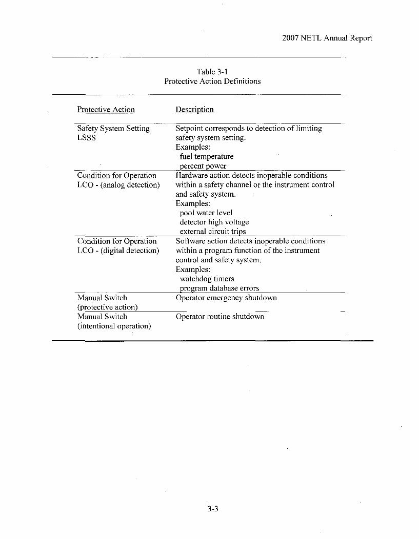
3.2 Reactor Shutdowns
The reactor safety system classifies protective action trips as one of three types, a limiting
safety system (LSSS) trip, a limiting condition for operation (LCO) trip or a trip of the SCRAM
manual switch. In the event the switch is used for a normal reactor shutdown, the operation is
not considered a protective action shutdown. The following definitions in Table 3-1 classify the
types of protective actions recorded.
3-2
2007 NETL Annual Report
Table 3-1Protective Action Definitions
Protective Action Description
Safety System SettingLSSS
Condition for OperationLCO - (analog detection)
Setpoint corresponds to detection of limitingsafety system setting.Examples:
fuel temperaturepercent power
Hardware action detects inoperable conditionswithin a safety channel or the instrument controland safety system.Examples:
pool water leveldetector high voltageexternal circuit trips
Software action detects inoperable conditionswithin a program function of the instrumentcontrol and safety system.Examples:
watchdog timersprogram database errors
Operator emergency shutdown
Condition for OperationLCO - (digital detection)
Manual Switch(protective action)Manual Switch(intentional operation)
Operator routine shutdown
3-3

2007 NETL Annual Report
Non-Scheduled Scrams for 2007 Calendar Year
Date: 2/09/07-12/3/2007
Scram Type: Fuel Temperature 1
Intermittent fuel temperature scram. Total of 10 spurious fuel temperature scrams recorded in
2007. Problem is very intermittent and has been investigated.
Date: 2/21/07
Scram Type: Manual Scram
Manual scram at SRO direction caused by Beam Port #5 Area Radiation Monitor during reactor
startup. Unknown and unexpected source of radiation was later traced to experimenter leaving
polyethylene shield up following previous day's radiography experiments.
Date: 5/17/07
Scram Type: High Power Scram. Error caused by reactor operator withdrawing control rods
near a scram setpoint.
Date: 10/16/07 and 11/28/07
Scram Type: Percent Power NM- 1000 High. Scram caused by fluctuations in neutron signal
near scram setpoint.
3.3 Utilization
The NETL staff continues to perform activation and analysis services as a public service
and in support of the overall UT mission. Neutron activation analysis accounted for much of the
reactor utilization time with teaching labs and beam port research projects making up the
remainder. The Prompt Gamma Analysis System was in use for much of the year for student
projects.
3.4 Routine Scheduled Maintenance
All surveillances and scheduled maintenance were completed during the reporting year.
All results met or exceeded the limits of the Technical Specifications.
3-4

2007 NETL Annual Report
3.5 Facility Changes and Corrective Maintenance
No facility changes requiring a 10 CFR 50.59 review were performed.
3.6 Laboratory Inspections
Inspections of laboratory operations are conducted by university and licensing agency
personnel. Two committees, a Radiation Safety Committee and a Reactor Oversight
Committee, review operations of the NETL facility. The Reactor Oversight Committee
convened at the times listed in Table 3-6.
Table 3-6Committee Meetings
Reactor Oversight Committee
First Quarter March 22, 2007Second Quarter No meetingThird Quarter October 22, 2007Fourth Quarter No meeting
Inspections by licensing agencies include federal license activities by the U. S. Nuclear
Regulatory Commission (NRC), Nuclear Reactor Regulation Branch (NRR), and state license
activities by the Texas Department of Safety and Health Services (DSHS). NRC and DSHS
inspections were held at the times presented in Table 3-7. An NRC inspection was performed
the week of November 4, 2007. The inspection included organizational structure and staffing,
review and audit of design changes (50.59), radiation program, environmental protection, health
physics procedures and transportation of radioactive material. No violations or safety concerns
were noted.
3-5
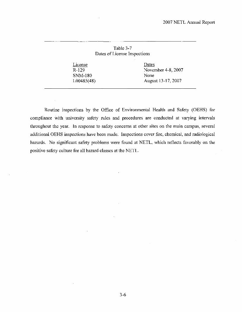
2007 NETL Annual Report
Table 3-7Dates of License Inspections
License DatesR-129 November 4-8, 2007SNM-180 NoneL00485(48) August 13-17, 2007
Routine inspections by the Office of Environmental Health and Safety (OEHS) for
compliance with university safety rules and procedures are conducted at varying intervals
throughout the year. In response to safety concerns at other sites on the main campus, several
additional OEHS inspections have been made. Inspections cover fire, chemical, and radiological
hazards. No significant safety problems were found at NETL, which reflects favorably on the
positive safety culture for all hazard classes at the NETL.
3-6

2007 NETL Annual Report
3.7 Radiation Exposures
A radiation protection program for the NETL facility provides monitoring for personnel
radiation exposure, surveys of radiation areas and contamination areas, and measurements of
radioactive effluents. Radiation exposures for personnel, building work areas and areas of the
NETL site are shown in the following tables. Site area measurements include exterior points
adjacent to the building and exterior points away from the building.
Table 3-8 summarizes NETL personnel dose exposure data for the calendar year. In
general, personnel exposures for 2006 were in line and less than 10% of the allowed 5000 mrem.
Figure 3-3 locates the building internal and external dosimetry sites. Dots locate fixed
monitoring points within the building. Numbers identify the immediate site area radiation
measurement points exterior to the building. These measurements do not indicate any
measurable dose from work within the NETL building. Table 3-9 and Table 3-10 summarize
doses recorded in facility work areas and the site areas. Table 3-11 contains a list of the basic
requirements and frequencies of measurements.
Additional measurement data is available from the State of Texas Department of Health.
The state agency records environmental radiological exposures at five sites in the vicinity of the
research reactor site. Samples are also taken for analysis of soil, vegetation, and sanitary waste
effluents.
3-7

2007 NETL Annual Report
Table 3-8
Personnel exposures for Year 2007
" Personnel exposures for 2007 were less than 10% of the federally allowed maximum of5000 mrem. Personnel whole body exposures did exceed 10% of the NETL local limit of1000 mrem, primarily due to the transfer of 156 60Co pencils in February 2007.
* The highest exposures for 2006 were 344 mrem whole body (375 mrem via pocketdosimeter) and 570 mrem extremity.
Personnel # Average Annual Dose Greatest Individual Dose Total Person mrem perGroup (mrem) (mrem) Group (mr 2
Whole Lens of Extremity Whole Lens of Extremity Whole Lens of ExtremityBody Eye (SDE) Body Eye (SDE) Body Eye (SDE)
(DDE) (LDE) (R/L) (DDE) (LDE) (R/L) (DDE) (LDE) (R/L)
Facility 148.8/ 1910/Personnel 12.8 81.0 87.8 344 350 500/570 1040 1127
(Landauer)3 140.3 1800
FacilityPersonnel(Landauer 12.8 67.6 - - 375 - - 865 -(Landauer
+ PD)4
FacilityPersonnel 14.3 0.70 - 10(PD only)
5
FacilityPersonnel 27.1 32.3 - 375 875(PD total)
6
Visitors(PD)7 702 0.080 N/A N/A 5 N/A N/A 56.5 N/A N/A
RadiationWorkersfro er 4 15.3 40 61from other
Facilities8
1. The number of facility personnel is calculated by summing the fraction of the year that anindividual person worked.
2 The total recorded dose equivalent values reported in mrem do not include the contribution fromnatural background and reflect the summation of the results of 12 monthly beta, x-, and gamma rayand/or neutron dosimeters in each location. A total dose equivalent of "M" indicates that each of
the dosimeters during the period was below the vendor's minimum measurable quantity of 1 mremfor x- and gamma rays, 10 mrem for energetic betas, 20 mrem for fast neutrons, and 10 mrem forthermal neutrons. "N/A" indicates that the measurement was not applicable and/or not measured.
3. This only includes those personnel assigned dosimetry from Landauer.4. This indicates those personnel who were assigned from Landauer as well as facility pocket dosimetry.5. This indicates personnel who were assigned facility pocket dosimetry only.6. This indicates all personnel working at the facility as radiation workers.7. This includes members of the public as well as those students enrolled in classes at the University of Texas at Austin.8. This indicates those outside radiation workers that were involved in the Co-60 shipment in February 2007.
3-8

2007 NETL Annual Report
Table 3-9
TOTAL DOSE EQUIVALENT RECORDED ON AREA DOSIMETERS LOCATED WITHIN THENETL FACILITY 2007
Reactor Facility Location Monitor ID Total Dose (1,2) Eye (4) Shallow (5)Reactor__FacilityLocation _MonitorID I,y,x Deep (3)Reactor Bay, North Wall 00277 35 62 166Reactor Bay, East Wall 00278 21 33 166Reactor Bay, West Wall 00279 24504 24868 25939Water Treatment Room 00280 28707 29152 29607Area, Room 1.102 00281 M M M
Sample Processing, Room 3.102 00173 4 4 5Gamma Spectroscopy Lab, Room 3.112 00174 M M MRadiation Experiment Lab, Room 3.106 00175 18 18 18Reception Area, Room 2.102 00176 M M MOffice, Room 3.104 00222 M M 2
1) The total recorded dose equivalent values reported in mrem do not include natural background contribution and reflect thesummation of the results of 12 monthly beta, x-, and gammy ray or neutron dosimeters for each location. A total dose equivalentof"M" indicates that each of the dosimeters during the period was below the vendor's minimum measurable quantity of I mremfor x and gamma rays, 10 mrem for energetic betas, 20 mrem for fast neutrons, and 10 mrem for thermal neutron. "N/A"indicates that there was no neutron monitor in that location.2) These dose equivalent values do not represent radiation exposure through an exterior wall directly into an unrestricted area.3) Deep indicates Deep Dose Equivalent and applies to external whole-body exposure and is the dose equivalent at a tissue depthof 1 cm.4) Eye indicates Eye Dose Equivalent and applies to external exposure of the lens at a depth of 0.3 cm.5) Shallow indicates Shallow Dose Equivalent and applies to external exposure of the skin or an extremity, and is taken as thedose equivalent at a tissue depth of 0.007 cm averaged over an area of I cm
2.
Table 3-10
TOTAL DOSE EQUIVALENT RECORDED ON TLD ENVIRONMENTALMONITORS AROUND THE NETL REACTOR FACILITY 2007
Total Recorded Dose EquivalentMonitor ID Reactor Facility Location (o) (mre m)
(1) (torero)
00156 Sidewalk, NETL Front Entrance M00157 NETL Power Transformer M00158 NETL Roof Stack 30#00159 Reactor bay exterior wall, East 40#00160 Reactor bay exterior wall, West 250*___ _
00161 NETL Service Door 30*__1) The total recorded dose equivalent values reported in mrem do not include natural background contribution and reflect thesummation of the results of 12 monthly beta, x-, and gamma or neutron dosimeters in each location. A total dose equivalent of"M"indicates that each of the dosimeters during the period was below the vendor's minimum measurable quantity of I mrem for x- andgamma rays, 10 mrem for energetic betas, 20 mrem for fast neutrons, and 10 mrem for thermal neutrons.*) Control was not subtracted by Landauer in first quarter 2007. Control would have subtracted -30 mrem.#) Control was not subtracted by Landauer in fourth quarter 2007. Control would have subtracted -30 mrem.@) The radioactive materials storage area is located on the west side of the reactor bay. The higher dose is due to the Co-60 shipmentin February 2007. Dose due to the Co-60 shipment is approximately 160 mrem.
3-9

2007 NETL Annual Report
Figure 3-3 Environmental TLD Locations
Sidewalk, NETL facility frontentranceReactor bay exterior wall, eastReactor bay exterior wall, westNETL power transformerNETL service doorNETL roof stack
Indicates location of dosimetrywithin the building
3-10

2007 NETL Annual Report
Table 3-11Radiation Protection Program
Requirements and Frequencies
Frequency Radiation Protection Requirement
Weekly Gamma survey of all Restricted Areas.Swipe survey of all Restricted Areas.Swipe survey of Radioactive Materials Areas.Response check of the continuous air monitor.Response checks of the area radiation monitors.Neutron survey of the reactor bay (during reactor operation).
Monthly Gamma, neutron and swipe surveys of exterior walls and roof.Exchange personnel dosimeters and interior area monitoringdosimeters.Review dosimetry reports.Response check emergency locker portable radiationmeasuring equipment.Review Radiation Work Permits.Response check of the argon monitor.Response check hand and foot monitor.Conduct background checks of low background alpha/betacounting system.Collect and analyze TRIGA primary water.
As Required Process and record solid wastes and liquid effluent discharges.Prepare and record radioactive material shipments.Survey and record incoming radioactive materials.Perform and record special radiation surveys.Issue radiation work permits and provide health physicscoverage for maintenance operations.Conduct orientations and training.
Quarterly Exchange TLD environmental monitors.Gamma and swipe surveys of all non restricted areas.Swipe survey of building exterior areas.Calibrate area monitors in neutron generator room.Perform Chi-square test, and determine HV plateaus anddetection efficiencies on the low background alpha/betacounting system.
Semi-Annual Inventory emergency locker.Calibrate portable radiation monitoring instruments.Calibrate continuous air monitor, argon monitor, and arearadiation monitors.Calibrate personnel pocket dosimeters.Leak test and inventory sealed sources.
Annual Conduct ALARA Committee meeting.Conduct personnel refresher training.Calibrate emergency locker portable radiation detectionequipment
3-11
2007 NETL Annual Report
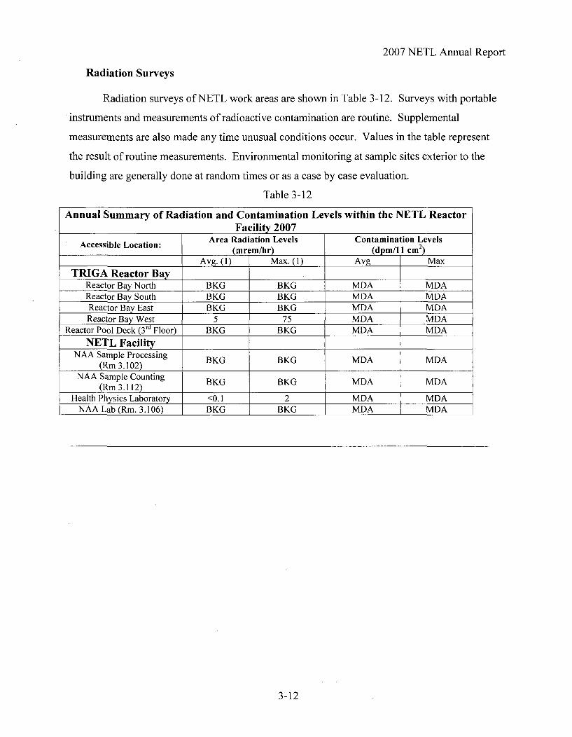
Radiation Surveys
Radiation surveys of NETL work areas are shown in Table 3-12. Surveys with portable
instruments and measurements of radioactive contamination are routine. Supplemental
measurements are also made any time unusual conditions occur. Values in the table represent
the result of routine measurements. Environmental monitoring at sample sites exterior to the
building are generally done at random times or as a case by case evaluation.
Table 3-12
Annual Summary of Radiation and Contamination Levels within the NETL ReactorFacility 2007
Area Radiation Levels Contamination LevelsAccessible Location: (mrem/hr) (dpm/11 cm2)Avg. (1) Max. (1) Avg Max
TRIGA Reactor BayReactor Bay North BKG BKG MDA MDAReactor Bay South BKG BKG MDA MDAReactor Bay East BKG BKG MDA MDAReactor Bay West 5 75 MDA MDA
Reactor Pool Deck (3 rd Floor) BKG BKG MDA MDANETL Facility
NAA Sample Processing BKG BKG MDA MDA(Rm 3.102)
NAA Sample Counting BKG BKG MDA MDA(Rm 3.112)
Health Physics Laboratory <0.1 2 MDA MDANAA Lab (Rm. 3.106) BKG BKG MDA MDA
3-12

2007 NETL Annual Report
3.9 Radioactive Effluents, Radioactive Waste
Radioactive effluents are releases to the air and to the sanitary sewer system. The most
significant effluent is an airborne radionuclide, argon-41. Two other airborne radionuclides,
nitrogen- 16 and oxygen-19, decay rapidly and do not contribute to effluent releases. Argon-4 1,
with a half-life of 109 minutes is the only airborne radionuclide emitted by the facility. A
summary of the argon-41 releases are shown in Table 3-13. Total quantity of Ar-41 released in
2006 was 3.95% of the T.S. allowance. This is based on a conservative dilution factor.
Evaluation of the radioactive gaseous effluent by the COMPLY code indicates the NETL is in
compliance with dose limits to the public with a calculated effective dose equivalent of 4.8
mrem/yr at the conservative receptor point.
Table 3-13Monthlv Summarv of Armon-41 Effluent Releases 2007 (1)
6 Total Quantity 4Ar Average Concentration Percentage of 41ArDischarge Date, 2006 To eal d Q tity A of 41Ar at Point of Released relative to
Released (jCi) Release Tech Spec.January 2.15E5 3.68E-8 1.84February 2.13E6 3.64E-7 18.2
March 2.06E6 3.53E-7 17.7April 2.04E6 3.49E-7 17.5May 1.44E6 2.46E-7 12.3June 1.26E6 2.16E-7 10.8July 6.95E5 1.19E-7 5.95
August 2.30E5 3.94E-8 1.97September 4.06E5 6.95E-8 3.47
October 1.12E6 1.92E-7 9.60November 1.25E6 2.13E-7 10.65December 1.65E6 2.82E-7 14.09
ANNUAL VALUE 1.45E7 2.48E-6 10.331) Point of release is roof exhaust stack. Concentration includes dilution factor of 0.2 for mixing with main exhaust.2) Technical Specification limit for continuous release is 2.OOE-6 ýICi/cm 3.
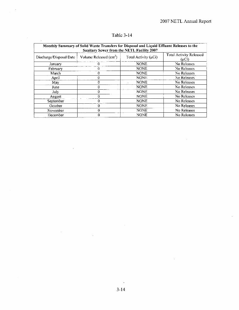
Large liquid releases to the sanitary sewer are done from waste hold up tanks at irregular
intervals. To date, no releases have been made. The liquid radioactive waste tanks allow for
segregation of liquids for decay of the activity. Liquids may also be processed on-site to
concentrate the radionuclides into other forms prior to disposal. Small quantities of liquid
scintillation cocktail or dilute concentrations may be disposed directly to the sanitary sewer if
below the limits of 10 CFR 20. There were no solid waste transfers off the NETL R-129 License
in 2007.
3-13
2007 NETL Annual Report
Table 3-14
Monthly Summary of Solid Waste Transfers for Disposal and Liquid Effluent Releases to theSanitary Sewer from the NETL Facility 2007
Total Activity ReleasedDischarge/Disposal Date Volume Released (cm 3) Total Activity (pCi) (ýCi)
January 0 NONE No ReleasesFebruary 0 NONE No Releases
March 0 NONE No ReleasesApril 0 NONE No ReleasesMay 0 NONE No Releases
June 0 NONE No ReleasesJuly 0 NONE No Releases
August 0 NONE No ReleasesSeptember 0 NONE No Releases
October 0 NONE No ReleasesNovember 0 NONE No ReleasesDecember 0 NONE No Releases
3-14