The University of Jordan School of Engineering...
104
Design n of Hyd draulic 0 and Pn 090853 09 neumat 3 7 tic Syst tem Lab b The University of Jordan School of Engineering Mechatronics Engineering Department
Transcript of The University of Jordan School of Engineering...

Designn of Hyddraulic
0
and Pn
090853
09
neumat
37tic Systtem Labb
The University of Jordan
School of Engineering
Mechatronics Engineering Department

LabExperiments DesignofHydraulicandPneumaticSystemLab
2Page Copyrights’areheldbyEng.RashaNoufal
EXPERIMENT N0. 1
Introduction to Automation Studio
Experiments No. Experiments Name Page No.
UNIVERSITY OF JORDAN
FACULTY OF ENGINEERING & TECHNOLOGY
MECHATRONICS ENGINEERING DEPARTMENT
DESIGN OF HYDRAULIC AND PNEUMATIC SYSTEM LAB
Modified & Revised By: Eng. Rasha Noufal / 2009
EXPERIMENTS
PartNo.1 IntroductiontoFluidSIM Program 3
PartNo.2 BasicCircuits 8

LabExperiments DesignofHydraulicandPneumaticSystemLab
3Page Copyrights’areheldbyEng.RashaNoufal
Objective: Students develop a hydraulic and pneumatic circuit in FluidSIM. The student should be able to build the circuit using FluidSIM and try different loads in order to realize its effect on the system performance.
To understand how a double acting cylinder can be controlled using a four‐way directional valve.
Flow rate: ‐1
is the volume of fluid passing a point in a given period of time.
Metric units: Flow rate (I/min) = Velocity (cm/min) × Area (cm2)
1000 .
English units: Flow rate (gal(us)/min) = Velocity (in/min) × Area (in2)
231
Velocity: ‐2
is the average speed of a particle of fluid past a given point.
: Flow rate and rod speed ‐3
The speed at which a cylinder rod moves is determined by how fast the pump can fill the volume
behind the cylinder piston.
The speed of cylinder rod (V) is calculated by dividing the oil flow rate (Q) by the piston area (A)
being acted upon.
Rod speed (V) = Flow rate (Q)
Piston area (A)
University Of Jordan
Faculty of Engineering & Technology
Mechatronics Engineering Department
Design of Hydraulic & Pneumatic System Lab
Experiments No.1
Introduction to FluidSIM
Modified & Revised By: Eng. Rasha Noufal / 2009
Part one ‐ A : Control of a Double Acting Cylinder

LabExperiments DesignofHydraulicandPneumaticSystemLab
4Page Copyrights’areheldbyEng.RashaNoufal
Extension speed
Metric units: V (cm/s) = Q (l/min) × 1000
Af (cm2) × 60 .
English units: V (in/s) = Q (gal (US) /min) × 231
Af (in2) × 60
Af = π × r2 = π × D2/4
Retraction speed
Metric units: V (cm/s) = Q (l/min) × 1000
Aa (cm2) × 60 .
English units: V (in/s) = Q (gal (US) /min) × 231
Aa (in2) × 60
Aa = ( π × D2/4 )‐ ( π × d2/4 )
= ( D2‐d2 ) × π / 4

LabExper
Copyrights
Pascal' ‐4
Pascal's La
direction,
The gener
of the sto
Metric un
English un
After you
Schematic
riments
s’areheldby
Law:s
aw states th
, and acts w
rated press
opper.
nits:
nits:
have been
c diagram in
P
yEng.Rasha
hat pressur
with equal fo
ure is equa
Press
Press
introduced
n Fig.
Fig.1
art one ‐
aNoufal
e applied o
orce on equ
l to the forc
sure (KPa) = F
sure (Psi) = Fo
Ar
d to the vari
Double Act
‐ B: Build
D
n a confine
ual areas, an
ce applied t
Force (N) × 1
Area (cm2)
orce (lb)
rea (in2)
iant blocks o
ing Cylinder
d the circ
esignofHyd
d fluid is tra
nd at right a
to the top o
10
of the Fluid
r Control Ci
cuit using
draulicand
ansmitted u
angles to th
f the stopp
SIM, You ar
rcuit
g FluidSI
PneumaticS
undiminishe
em.
er divided b
.
re now read
M
SystemLab
5Page
ed in all
by the area
dy to build

LabExper
Copyrights
NOTE: ThRelief valvpiston arerode areastroke lenpump flowpump spe
riments
s’areheldby
he componeve setting aea = 20 in2 a = 10 in2 ngth = 50 in w = 25 gpmeed = 1200
yEng.Rasha
ents settingt 1500 psi
rpm.
aNoufal
Fig.2 Reg
Fig.3 Re
gs and dime
D
generative C
egenerative
nsions are a
esignofHyd
Circuit
e Circuit
as following
draulicand
g:
PneumaticSSystemLab
6Page

LabExperiments DesignofHydraulicandPneumaticSystemLab
7Page Copyrights’areheldbyEng.RashaNoufal
Date:
Section:
Group's Names:
1‐
2‐
3‐
4‐
Q1: Brief description of how the above circuits work.
Q2: Calculate the extracting and retracting cylinder speeds in both cases (normal and regenerative)? Comment on the results.
Q3: Calculate the maximum load that can be attached to the cylinder in both cases? Comment on the results.
Q4: What is the purpose of a regenerative circuit? (Use equations to explain that).
University Of Jordan
Faculty of Engineering & Technology
Mechatronics Engineering Department
Design of Hydraulic & Pneumatic System Lab
Experiments No.1
Introduction to FluidSIM
Modified & Revised By: Eng. Rasha Noufal / 2009
In class Lab Report
Part three: Procedure

LabExper
Copyrights
Objectiv
Hydraulic
complex.
For exam
need to e
software
training, a
To unders
Operation
A hydraul
1‐ The res
2‐ The pu
3‐ The dir
cylinder.
riments
s’areheldby
ve: Stu pn Th va
and pneum
Controlling
ple, two cyl
xtend rapid
tool. It was
and testing
stand the se
n of a basic
ic circuit is
servoir hold
mp (pushes
rectional co
Part t
yEng.Rasha
udents Devneumatic cirhe student salve.
matic system
g cylinder is
linders may
dly under no
created for
requiremen
equence cir
c hydraulic c
a path for O
ds the oil
s) the oil, at
ontrol valve
Facu
Mech
Design o
Modi
two – A
aNoufal
velop, connercuit in Fluihould be ab
ms perform
one of the
y be require
o load cond
r the autom
nts.
rcuit and to
: circuit
Oil to flow t
ttempting t
e allows the
Unive
ulty of Eng
hatronics E
of Hydrau
P
Ba
ified & Revi
In
: Hydrau
D
ection and oidSIM. ble to descri
a variety of
most impo
ed to operat
itions. Fluid
mation indus
know how
through hos
o make it fl
operator to
ersity Of Jo
gineering
Engineerin
ulic & Pneu
Part No.2
asic Circui
ised By: Eng
troducti
ulic Cylind
esignofHyd
operation of
ibe the oper
f tasks, rang
rtant aspec
te at the sam
dSIM is a d
stry, specifi
build such
ses and com
ow through
o manually
ordan
& Techno
ng Depart
umatic Sy
2
its
g. Rasha No
on
der Sequ
draulicand
f simple, pra
ration of a d
ging from v
cts of hydrau
me speed, o
esign, anim
cally to fulf
circuit using
mponents.
h the circuit
control the
ology
tment
ystem Lab
oufal / 2009
uence Cir
PneumaticS
actical hydr
directional c
ery simple t
ulics and pn
or a cylinde
mation and s
fill engineer
g FluidSIM
t.
e oil flow to
9
rcuit
SystemLab
8Page
aulic and
control
to the very
neumatics.
r may
simulation
ring,
M.
the

LabExper
Copyrights
4‐ The cyl
5‐ The rel
back to th
Build the
have been
build Sche
NOTE: ThRelief valvFor both cpiston arerode areastroke lenpump flowpump spe
riments
s’areheldby
linder conve
ief valve lim
he reservoir
circuit usin
n introduce
ematic diag
he componeve setting acylinder: ea = 20 in2 a = 10 in2 ngth = 50 in w = 25 gpmeed = 1200
yEng.Rasha
erts fluid en
mits system
r when pres
luidSIMFng
ed to the va
gram in Fig.
ents settingt 1500 psi
rpm.
aNoufal
nergy into li
m pressure to
ssure at the
:
riant compo
using Fluid
Fig.1 Hydr
gs and dime
D
inear mech
o a safe lev
pump outp
onents of th
dSIM.
raulic Seque
nsions are a
esignofHyd
anical powe
el by allowi
put reaches
he hydraulic
ence Circuit
as following
draulicand
er.
ng oil to flo
s a certain le
c system, yo
t
g:
PneumaticS
ow directly f
evel.
Aft
ou are now
SystemLab
9Page
from pump
ter you
ready to

LabExper
Copyrights
To show h
Moreover
specificat
Build the
After you
ready to b
riments
s’areheldby
how two ide
r, this lab is
ions in orde
circuit usin
have been
build Schem
Part
yEng.Rasha
entical cylin
aimed at p
er to synchr
luidSIMFng
introduced
matic diagra
t two – B
aNoufal
nders can be
providing th
ronize the m
:
d to the vari
m in Fig. us
Fig.2 Par
Fig.3 Se
B: Paralle
D
e synchroni
e students
motion of tw
iant compo
sing FluidSI
rallel Cylind
eries Cylinde
el and Se
esignofHyd
ized by pipi
with ideas o
wo cylinder
nents of the
IM.
er Circuit
er Circuit
eries cylin
draulicand
ng them in
on how to c
s connected
e hydraulic
nder Circ
PneumaticS
parallel and
change the
d in series.
system, yo
cuits
SystemLab
10Page
d series.
cylinders
u are now

LabExper
Copyrights
Flow Cont
this exper
difference
A flow co
adjusting
and, there
Flow cont
There are
meter‐in
With the
the cylind
delivered
With the
and the re
delivered
Build the
have been
build Sche
Part
riments
s’areheldby
trol Valves
riment is to
e between t
ntrol valve
the resistan
efore, the s
trol circuits
e two ways t
and meter‐
meter‐in m
der, as figur
by the pum
meter‐out
eservoir, as
by the pum
circuit usin
n introduce
ematic diag
Fig.3 Me
t two – C
yEng.Rasha
(FCVs) are u
illustrate t
them.
as an adjus
nce, or ope
peed of its
s:
to meter th
‐out.
method, the
e 4 shows.
mp is draine
method, th
figure 5 sh
mp is draine
luidSIMFng
ed to the va
gram in Fig.
eter‐in spee
C : Meter
aNoufal
used in indu
he circuit fo
stable resist
ning, of this
piston rod.
e oil flow in
flow contro
It restricts t
ed back to th
he flow cont
ows. It rest
ed back to th
:M
riant compo
using Fluid
d control of
r‐in vs. M
D
ustry for cyl
or meter‐in
tance to flo
s valve, you
n order to c
ol valve is co
the working
he reservoi
trol valve is
tricts the flo
he reservoi
onents of th
dSIM.
f hydraulic
Meter‐ou
esignofHyd
inder speed
and meter‐
w that ope
u can modify
ontrol the s
onnected in
g oil flow to
r through th
s connected
ow away fro
r through th
he hydraulic
cylinder du
t Flow Co
draulicand
d control. T
‐out speed
rates very m
y the rate o
speed of a c
n series betw
the cylinde
he relief val
d in series b
om the cylin
he relief val
c system, yo
ring extend
ontrol V
PneumaticS
herefore, th
control as w
much like a
of oil flow to
cylinder, wh
ween the p
er. The extra
lve.
etween the
nder. The ex
lve.
Af
ou are now
ding stroke
alve Syst
SystemLab
11Page
he aim of
well as the
faucet. By
o a cylinder
hich are:
ump and
a flow
e cylinder
xtra flow
fter you
ready to
tem

LabExper
Copyrights
NOTE: TheRelief valvepiston diamrode diamstroke lengpump disppump speeFCV diame
riments
s’areheldby
Fig.4 Met
e componene setting at 2meter = 6 in eter = 2 in gth = 50 in placement = 0ed = 1800 rpeter = 0.09 in
yEng.Rasha
ter‐out spee
ts settings a2000 psi
0.026 g/rev m n .
aNoufal
ed control o
nd dimensio
D
of hydraulic
ons are as fol
esignofHyd
c cylinder du
lowing:
draulicand
uring extend
PneumaticS
ding stroke
SystemLab
12Page

LabExperiments DesignofHydraulicandPneumaticSystemLab
13Page Copyrights’areheldbyEng.RashaNoufal
Date:
Section:
Group's Names:
1‐
2‐
3‐
4‐
5‐
Q1: Brief description of how the circuits Fig.1 work.
Q2: Calculate the maximum load that can be attached to the cylinder? Comment on the results.
University Of Jordan
Faculty of Engineering & Technology
Mechatronics Engineering Department
Design of Hydraulic & Pneumatic System Lab
Part Two No.2
Basic Circuits
Modified & Revised By: Eng. Rasha Noufal / 2009
In class Lab Report
Part one: Hydraulic Cylinder Sequence Circuit

LabExperiments DesignofHydraulicandPneumaticSystemLab
14Page Copyrights’areheldbyEng.RashaNoufal
Q1: Brief description of how the above circuits work.
Q2: For the series cylinder circuit, what pump pressure is required if the cylinder loads are 5000 lb each and cylinder 1 has a piston area of 10 in2?
Q1: What are the stroke speeds in both cases at 10%,50%,80% and 100% FCV opening?
Q2:Design a meter‐in and meter‐out control circuit of hydraulic cylinder during retracting stroke. The following data are given: Desired speed = 10 in/s. Cylinder piston diameter = 2 in. Cylinder load: 4000 lb. PRV setting= 1000 psi.
Part two: Parallel and Series cylinder Circuits
Part three: Meter‐in vs. Meter‐out Flow Control Valve System

Copyrights’ are held by University of Jordan 1
Objective: Students will be able to control of double-acting cylinder, and knowing various
types of speed regulation of the piston rod movement of double-acting cylinder.
Pneumatics system performs a variety of tasks, ranging from the very simple to the very complex. Controlling cylinders is one of the most important aspects of pneumatics. For example, two cylinders may be required to operate at the same speed, or a cylinder may need to extend rapidly under no load conditions.
Pre-Lab: the required pneumatic circuit diagrams using the FluidSIM; show the whole
connections and components required for each circuit.
In the lab: Connect the circuits and verify their operation. sure that the pressure is 4
bars and is connected correctly. Double check your connections before switching the compressor on.
Direct control of a double-acting cylinder with push-button.
Aim: This exercise provides direct control of double-acting cylinders with manually operated
5/2 directional control valves. In addition, the effect of adjustable spring cushioning in double-acting cylinders can be observed.
Task: - The piston rod of a double-working cylinder (Z1) should extend after actuating a button. - After releasing the button (S1), the piston of the cylinder should retract automatically to
its back position.
University Of Jordan
Faculty of Engineering & Technology
Mechatronics Engineering Department
Design of Hydraulic & Pneumatic System Lab
Experiments No.2Pneumatic Control of a Double-acting Cylinder
Introduction
Part one: Control of a double-acting cylinder
Pre-Lab

Lab Experiments Control of Hydraulic and Pneumatic System Lab
Copyrights’ are held by University of Jordan 2
List of equipment: Description:
- (01) Air service unit (filter with water separator, pressure regulator and pressure gauge) with 3/2 directional control ball valve
- (02) Distributor, 6-fold - (04) Double-acting cylinder with adjustable spring cushioning - (08) 5/2 directional control valve with push-button Accessories
Figure 2.1: Direct control of a double-acting cylinder
Conclusion: - The double-acting cylinder can be directly controlled by a ________________________. - In the basic setting (spring position) of a directional valve, port 1 supplied with
compressed air, port 2 is always __________ and port 4 always____________.

Lab Experiments Control of Hydraulic and Pneumatic System Lab
Copyrights’ are held by University of Jordan 3
Aim: In this exercise, the various types of speed regulation (throttling) of the piston rod
movements of double-acting cylinders with one-way flow control valves are looked at and the effects are observed.
Task: - The cylinder is controlled with a manually operated button (actuator S1). After releasing
the button (S1), the piston of the cylinder should retract automatically to its back position.
List of equipment: Description:
- (04) Double-acting cylinder with adjustable spring cushioning - (08) 5/2 directional control valve with push-button Accessories - (15) Flow control valves with non-return, adjustable
Figure 2.2: Speed regulation of a double-acting cylinder Conclusion:
Referring to figure 2, which circuit demonstrates the following? a. In Circuit (________): The speed of the cylinder piston is restricted when extending.b. In Circuit (________): The speed of the cylinder piston is restricted when retracting.c. In Circuit (________): Both speed of the cylinder piston are restricted.
Part two: Speed regulation of a double-acting cylinder

Lab Experiments Control of Hydraulic and Pneumatic System Lab
Copyrights’ are held by University of Jordan 4
Aim:In this exercise we examine how a pneumatically operated impulse valve functions when controlling a double acting cylinder. Upon the completion of this task, the student will be
• Familiar with indirect actuation of a double acting cylinder by using a double pilot valve.• Using the 3/2 way roller valve for automatic return of the cylinder.
Task description: Wooden planks are to be pushed along from a gravity feed magazine to a clamping device as shown in Fig.3 By pressing a pushbutton valve one plank is pushed by the slide out of the gravity feed magazine. After the slide has reached the forward end position it returns to its start position.
Fig. 2.3: Positional sketch
List of equipment: Description:
- (04) Double-acting cylinder with adjustable spring cushioning - (11) 5/2 directional control valve, impulse valve - (15) Flow control valves with non-return, adjustable - (06) 3/2 directional control valve, with manually operated push-button - (07) 3/2 way roller valve for automatic return of the cylinder.
Task requirements:
1. Draw pneumatic circuit diagram to control the movement of the slide.2. Simulate the circuit using Fluid SIM software.3. Assemble the circuit practically and check its operation.
Part three: Controlling a double-acting cylinder with impulse valve

Lab Experiments Control of Hydraulic and Pneumatic System Lab
Copyrights’ are held by University of Jordan 5
Figure 2.4: Controlling a double-acting cylinder by impulse valve
System steps:
- Start the system by pressing S1, the cylinder _____________________________________ - After releasing S1, the cylinder ________________________________________________ - When S2 Pressing , the cylinder _______________________________________________ - If S2 is pressed momentarily, the cylinder _______________________________________
Conclusion:
- Impulse Valves are always controlled by ______________________________ - Is impulse valve has a basic setting?

Lab Experiments Control of Hydraulic and Pneumatic System Lab
Copyrights’ are held by University of Jordan 6
Aim: The displacement-dependent control of a double-acting cylinder by using limit switches in demonstrated in this exercise. Upon the completion of this task, the student will be
• Familiar with indirect actuation of a double acting cylinder by using a double pilot valve.• Familiar with using different types of directional control valves
Task description: Using a diverting device, parts are to be moved from one conveyor track onto the other in a linear sequence as illustrated in Fig. 2.5. By operating a selector valve the oscillating piston rod of a cylinder pushes the turntable via a pawl in stepped sequence. The parts are diverted and transported onwards in the opposite direction. By returning the selector valve back to the normal position the drive unit is switched off.
Fig. 2.5: Positional sketch
Task requirements: 1. Draw a pneumatic circuit diagram to control the operation of the piston.2. Simulate the circuit using FluidSIM software.3. Assemble the circuit practically and check its operation.
List of equipment: Description:
- (13) 3/2 directional control valves, with roller- (04) Double-acting cylinder with adjustable spring cushioning - (11) 5/2 directional control valve, impulse valve - (15) Flow control valves with non-return, adjustable - (06) 3/2 directional control valve, with manually operated push-button - (13) 3/2 way roller valve for automatic return of the cylinder.
Part Four: Displacement dependent control of a double-acting cylinder

Lab Experiments Control of Hydraulic and Pneumatic System Lab
Copyrights’ are held by University of Jordan 7
Figure 2.4 : Displacement dependent control of a double-acting cylinder
Conclusion:
- Design the functional diagram (stroke-time diagram) for the cylinder and the 5/2 directional control valve.
- What are used for a displacement dependent control of a double-acting cylinder?

Lab Experiments Control of Hydraulic and Pneumatic System Lab
Copyrights’ are held by University of Jordan 8
Aim: By using a 3/2 directional control valve with adjustable minimum pressure of response, a pressure dependent control (and in addition displacement dependent) control of a double acting cylinder is put into effect. Upon the completion of this task, the student will be
• Familiar with indirect actuation of a double acting cylinder with a double pilot valve.• Able to use and adjust the pressure sequence valve.
Task description: A plastic component is embossed using a die driven by a double-acting cylinder. The die is to advance and emboss the plastic when a push button is operated. The return of the die is to be effected when a preset pressure is reached. The embossing pressure is to be adjustable.
Fig. 2.5 Positional sketch
Task requirements: 1. Draw pneumatic circuit diagram2. Simulate the circuit using Fluid SIM software.3. Assemble the circuit practically and check its operation
List of equipment: Description:
- (21) Pressure gauge - (22) 3/2 directional control valve, with adjustable operating pressure - (13) 3/2 directional control valves, with roller- (04) Double-acting cylinder with adjustable spring cushioning - (11) 5/2 directional control valve, impulse valve - (15) Flow control valves with non-return, adjustable - (06) 3/2 directional control valve, with manually operated push-button - (13) 3/2 way roller valve for automatic return of the cylinder. -
Part Five: Pressure-dependent control of a double acting cylinder

Lab Experiments Control of Hydraulic and Pneumatic System Lab
Copyrights’ are held by University of Jordan 9
Figure 2.6 : Pressure dependent control of a double-acting cylinder Conclusion:
- Mention the conditions to extend the piston of the cylinder.
__________________________________________________________________
- Mention the conditions to retract the piston of the cylinder. __________________________________________________________________
- Design the functional diagram (stroke-time diagram) for the cylinder and the 5/2 directional control valve.

LabExper
Copyrights
Objectiv
Pre
In th
Aim: This exercspring ret
Title: DiveProblem dThe parts conveyor forward. Tanother p
Pa
riments
s’areheldby
ve: Th co ele
e‐Lab: the the
he lab: Bu an th
cise demonturn 5/2 dire
erting machdescriptionused in thetrack. By pThe part is mpushbutton
art I: Com
ytheUniver
his exerciseommissioninectric activa
required p
e whole con
uild your dend is connehe compres
strates the ectional con
hine n: e diverting mressing a pumoved oveswitch the
Fig 3.1
Fac
Mech
Contro
Elec
mmand‐
sityofJorda
s conveys bng an electration of a si
neumatic c
nections an
esigns and vected correcsor on.
control of antrol valve w
machine areushbutton sr and transpframe is ret
Positional s
Unive
ulty of En
hatronics
ol of Hydra
Ex
ctro pneu
variable
Co
n
basic knowlo pneumatiingle acting
ircuit diagra
nd compone
verify their octly. Double
a double‐acwithout the
e to be movswitch the fported onwturned to it
sketch of th
ersity Of J
gineering
Engineer
aulic & Pn
periment
umatics Co
control
Pre‐Lab
ontrolofHyd
edge and skc control uscylinder.
ams using t
ents require
operation. se check you
cting cylindee use of a re
ved from onrame of the
wards in the ts start posi
e diverting
ordan
g & Techno
ing Depar
neumatic S
s No.3
ontrol Tec
of a dou
draulicand
kills on settising the exa
he FluidSIM
ed for each
sure that thur connecti
er with an eelay.
ne conveyore diverting mopposite dtion as show
machine
ology
rtment
System La
chnology
uble actin
Pneumatic
ing up and ample of a d
M SW; show
circuit.
he pressureons before
electrically c
r track to anmachine is pirection. Bywn below in
ab
ng cylind
SystemLab
1Page
direct
w
e is 4 bars switching
controlled,
nother pushed y pressing n Fig 3.1
der

LabExper
Copyrights
List of equDescriptio
‐ (0‐ (3‐ (3‐ (5‐ (4‐ (0‐ (0
Procedure1.2. 3. 4.
Figu
Conclusio
‐ Th
‐ In wian
riments
s’areheldby
uipment: on: 04) Double32) 5/2 dir37) Unit, 150) Power42) Unit, e01) Pneum02) Compr
es: . Draw the eTest the cirConstruct tWrite dow
ure 3.2: Elec
on:
he double‐a
the basic seith________nd port 5 an
ytheUniver
e‐acting cyliectional con1 control swr supply unitelectric manmatic air serressed air d
elector‐pnercuit functiothe circuit on your note
ctric circuit d
cting cylind
etting (sprin_________,nd 3 are alw
sityofJorda
nder, with antrol impulswitch, 2 pusht nifold rvice unit istributor
eumatic circons against on the workes and obse
diagram
der can be d
ng position), port 2 is a
ways ______
Co
n
annular solese valve, eleh buttons
cuit using thany errors kstation rvations.
directly cont
) of a directlways ______________
ontrolofHyd
enoid ectrically co
he FluidSim or mistakes
Figure 3.3:
trolled by a
tional valve,_______ , po__________
draulicand
ontrolled
software s.
Pneumatic
_________
, port 1 suport 4 always__________
Pneumatic
circuit diag
__________
pplied s___________ .
SystemLab
2Page
ram
_______.
________

LabExper
Copyrights
‐ St
th
________
‐ Wele____
Aim: This exercvalve soleelements
Title: Bulk
Problem dBulk mateswitch, thpushbuttoHint: The
P
riments
s’areheldby
art the syst
e system do
________________________________________
What the initectrically co____________________
cise conveyenoids are c.
k material
descriptionerial is to behe hopper ison switch thcontrolling
Part II: H
ytheUniver
em by pres
o:
________________________________________
tial or centeontrolled ____________________
s knowledgcontrolled th
n: e emptied fs opened anhe hopper i circuit sho
Fig. 3.4 P
Holding e
sityofJorda
sing S1 mom
________________________________________
er position f
____________________
ge on the aphrough rela
rom a hoppnd the bulks closed agauld contain
Positional s
element c
Co
n
mentarily a
________________________________________
for (32) 5/2
____________________
pplication ofay contacts
per as showmaterial is ain. relays for t
sketch of
control o
ontrolofHyd
ssuming th
________________________________________
directional
____________________
f relays in eand not dir
n below in emptied ou
the indirect
the hoppe
of a doub
draulicand
at the switc
________________________________________
control imp
____________________
electro pneuectly throug
Fig.3.4. By put. By press
control
er machin
ble actin
Pneumatic
ch S0 is on ,
________________________________________
pulse valve,
____________________
umatic contgh the signa
pressing a ping another
ne
g cylinde
SystemLab
3Page
step what
__ __ __ __
,
__________________
trols. The aling
pushbutton r
er

LabExper
Copyrights
List of equDescriptio
‐ (0‐ (3‐ (3‐ (3‐ (5‐ (4‐ (0‐ (0
Procedure1. 2. 3. 4.
Conclusio
‐ St
____
riments
s’areheldby
uipment: on: 04) Double32) 5/2 dir37) Unit, 134) Relay u50) Power42) Unit, e01) Pneum02) Compr
es: Draw the eTest the cirConstruct tWrite dow
on:
art the syst
____________________
ytheUniver
e‐acting cyliectional con1 control swunit 4 changr supply unitelectric manmatic air serressed air d
elector‐pneurcuit functiothe circuit on your note
F
em by pres
____________________
sityofJorda
nder, with antrol impulswitch, 2 pushgeover contt nifold rvice unit istributor
umatic circuons against on the workes and obse
igure 3.5: P
sing S1 mom
____________________
Co
n
annular solese valve, eleh buttons tacts
uit using theany errors kstation rvations.
Pneumatic c
mentarily, s
____________________
ontrolofHyd
enoid ectrically co
e FluidSim sor mistakes
circuit diagra
step what th
____________________
draulicand
ontrolled
software s.
am
he system d
____________________
Pneumatic
do:
____________________
SystemLab
4Page
__ __

LabExper
Copyrights
‐ pr
____
‐ wh____
Aim: This exercdemonstr
Title: OpeThe doubDraw an eHint: The the valve
List of equDescriptio
‐ (0‐ (3‐ (3‐ (3‐ (5‐ (4‐ (0‐ (0
riments
s’areheldby
ressing S2 m
____________________
hat the diffe____________________
cise the varrated.
ening/closinle acting cyelectro‐pnevalve is opeis closed.
uipment: on: 04) Double31) 5/2 dir37) Unit, 134) Relay u50) Power42) Unit, e01) Pneum02) Compr
Part
ytheUniver
momentarily
____________________
erent betwe____________________
ious possib
ng the flowylinder (1A) umatic circened by pre
Fig
e‐acting cyliectional con1 control swunit 4 changr supply unitelectric manmatic air serressed air d
t III: Basi
sityofJorda
y, step what
____________________
een part on____________________
le circuits w
w in a pipelinin Fig. 3.6 isuit to contressing the p
g. 3.6 Pos
nder, with antrol impulswitch, 2 pushgeover contt nifold rvice unit istributor
ic Circuit
Co
n
t the system
____________________
ne and two ____________________
with latching
ne s used to oprol the movepushbutton
sitional ske
annular solese valve, eleh buttons tacts
t with ele
ontrolofHyd
m do:
____________________
____________________
g (storage c
pen and cloement of cyswitch. Wh
etch mach
enoid ectrically co
ectric lat
draulicand
____________________
____________________
circuits) in re
ose the mainylinder (1A)hen the push
hine
ontrolled, sp
tching cir
Pneumatic
____________________
____________________
elay techno
n valve in a . hbutton is r
pring return
rcuit
SystemLab
5Page
__ __
__________________
ology are
pipeline.
released
n

LabExper
Copyrights
Procedure
1.2. 3. 4.
Figure 3
Conclusio
‐ St
th
________
‐ wh____
riments
s’areheldby
es A:
Draw the eTest the cirConstruct tWrite dow
3.8: Electric
on:
art the syst
e system do
________________________________________
hat the diffe____________________
ytheUniver
elector‐pnercuit functiothe circuit on your note
c circuit diag
em by pres
o:
________________________________________
erent betwe____________________
sityofJorda
umatic circons against on the workes and obse
gram
sing S1 mom
________________________________________
een part tw____________________
Co
n
uit using thany errors kstation rvations.
mentarily a
________________________________________
wo and three____________________
ontrolofHyd
e FluidSim sor mistakes
Figure 3.7:
ssuming th
________________________________________
e ____________________
draulicand
software s.
Pneumatic
at the switc
________________________________________
____________________
Pneumatic
circuit diag
ch S0 is on ,
________________________________________
____________________
SystemLab
6Page
gram
step what
__ __ __ __
_______________

LabExper
Copyrights
Procedure 1.C
Conclusio
‐ St
th
________
riments
s’areheldby
es B:
Connect the
on:
art the syst
e system do
________________________________________
ytheUniver
e circuit sho
Figur
em by pres
o:
________________________________________
sityofJorda
own in Figu
re 3.8: Elect
sing S1 mom
________________________________________
Co
n
res 3.8.
tric circuit d
mentarily a
________________________________________
ontrolofHyd
diagram (do
ssuming th
________________________________________
draulicand
ominant "of
at the switc
________________________________________
Pneumatic
ff")
ch S0 is on ,
________________________________________
SystemLab
7Page
step what
__ __ __ __

LabExper
Copyrights
Aim: Cylinder sthis displa Problem dThe douborder to pstarts oscbackwar
List of equDescriptio
‐ (0‐ (3‐ (1‐ (3‐ (3‐ (3‐ (5‐ (4‐ (0‐ (0
Required
1. 2. 3. 4. 5.
Part I
riments
s’areheldby
switches anacement‐ de
descriptionle acting cyprovide a beillating. Tword strokes
uipment: on: 04) Double32) 5/2 dir15) one wa37) Unit, 134) Relay u38) Cylinde50) Power42) Unit, e01) Pneum02) Compr
procedureDraw the eThe speed Test the cirConstruct tWrite dow
V: Displa
ytheUniver
d an electriependent c
n: ylinder showelt timely mo limit switcs.
e‐acting cyliectional conay flow con1 control swunit 4 changer switchesr supply unitelectric manmatic air serressed air d
s electro‐pneuof the forwrcuit functiothe circuit on your note
acement
sityofJorda
cally controontrol of a
wn in Fig.3.9movement. Wches should
nder, with antrol impulsntrol valve witch, 2 pushgeover conts t nifold rvice unit istributor
umatic circuward and baons against on the workes and obse
t depend
Co
n
olled 5/2 dirdouble‐acti
9 below is uWhen the dd be used to
Fig.3.9
annular solese valve, ele
h buttons tacts
uit (indirectckward stroany errors kstation rvations.
dent cont
ontrolofHyd
rectional coing cylinder
used to genedetent switco control th
enoid ectrically co
t control) usoke of the cor mistakes
trol of a
draulicand
ontrol impur.
erate an oscch is turnede length of
ontrolled
sing the Flucylinder rods.
double a
Pneumatic
lse valve ar
cillating mo on, the pisthe forward
idSim softw is adjustab
acting cy
SystemLab
8Page
re used in
ovement in ton rod d and
ware ble
ylinder

LabExper
Copyrights
Fig. 3. Conclusio
‐ St
________
‐ De
dir
riments
s’areheldby
.10: Pneum
on:
art the syst
________________________________________
esign the furectional co
ytheUniver
atic circuit
em by pres
________________________________________
nctional diaontrol valve
sityofJorda
diagram
sing S0 mom
________________________________________
agram (stro.
Co
n
mentarily ,
________________________________________
oke‐time dia
ontrolofHyd
Fi
step what
________________________________________
agram) for t
draulicand
ig. 3.11: Ele
the system
________________________________________
the cylinder
Pneumatic
ctric circuit
do:
________________________________________
r and the 5/
SystemLab
9Page
t diagram
__ __ __ __
/2

Objective: Students will be able to identify the hydraulics Trainer components and to safely operate the
trainer.
The student should be able to state the laws governing hydraulic, and perform simple calculation
involving force, pressure, area, velocity, and flow rate.
Pressure is the amount of force exerted against a given surface. Flow is the movement of fluid caused by a difference in pressure between two points. Fluid always flows from a higher pressure point to a lower pressure point. When two parallel paths of flow are available, fluid will always take the path of least resistance.
In a hydraulic circuit, flow is produced by the action of a pump, which continuously discharges the oil at a certain flow rate. Pressure is not created by the pump itself but by resistance to the oil flow. When the oil is allowed to flow with no resistance through a hydraulic circuit, the pressure in that circuit is theoretical zero.
In the first part, you will identify the various components of your Hydraulics Trainer. The components illustrated in Figure 1 are supplied with your Hydraulics Trainer. Draw the symbol of each component:
University Of Jordan
Faculty of Engineering & Technology
Mechatronics Engineering Department
Design of Hydraulic & Pneumatic System Lab
Experiments No.4
Introduction to Hydraulic Trainer
Introduction
Part one: Identify the Hydraulic Trainer Components

Lab Experiments Design of Hydraulic and Pneumatic System Lab
2Page University of Jordan Copyrights’ are held by the
Fig.1 Identify the Hydraulics Trainers components

Lab Experiments Design of Hydraulic and Pneumatic System Lab
3Page University of Jordan Copyrights’ are held by the
The relief valve supplied with your kit of hydraulic components is called a pilot-operated type. The valve body has three parts: a pressure (P) port, which is to be connected to the pump pressure line, a tank (T) port, which is to be connected to the reservoir, and vent (V), which is to be used for control of the valve from a remote point by external valve. The pressure at which the relief valve begins to open is called cracking pressure.
In the part of the exercise, you measured the minimum pressure setting by a relief valve which is connected between the pump pressure line and reservoir and by opening the valve completely.
You then tested the effect of pressure limitation on a basic hydraulic circuit.
PROCEDURE
Connect the circuit shown in Figures 2 and 3. Make sure to mount the 3.81-cm (1.5-in) bore cylinder in a position where its rod can extend freely.
Fig.2 Schematic diagram of the cylinder actuation circuit
- Make sure the hoses are firmly connected. Open the Relief Valve completely by turning its
adjustment knob fully counterclockwise. - Turn on the power Unit. - Turn the Relief Valve adjustment knob clockwise until gauge A reads 1400 kPa (200 psi). - Stay clear of the cylinder rod. Move the lever of the Directional Control Valve toward the
valve body, which should extend the cylinder rod. Then, move the lever outward from the valve body, which should retract the rod.
Part two: Limiting System Pressure

Lab Experiments Design of Hydraulic and Pneumatic System Lab
4Page University of Jordan Copyrights’ are held by the
Fig.3 Connection diagram of the cylinder actuation circuit
- While watching the reading of gauge A, move the lever of the directional Valve toward the Valve body to extend the cylinder rod. What is the pressure at gauge A during the extension stroke of the rod?
Pressure = ---------------- KPa or ----------------- Psi
- What is the pressure at gauge A when the cylinder is fully extended?
Pressure = ---------------- KPa or ----------------- Psi
- Move the lever of the directional valve outward from the valve body to retract the cylinder rod.
- Turn relief Valve adjustment knob clockwise until gauge A reads 2100 kPa (300 psi). - While watching the reading of gauge A, move the lever of the directional valve toward the
valve body to extend the cylinder rod. What is the pressure at gauge A during the extension stroke of the cylinder rod?
Pressure = ---------------- KPa or ----------------- Psi
- What is the pressure at gauge A when the cylinder rod is fully extended?
Pressure = ---------------- KPa or ----------------- Psi
- Move the lever of the directional valve outward from the valve body to retract the cylinder rod.
- Turn off the Power Unit. Open the Relief Valve completely by turning its adjustment knob fully counter clockwise.

Lab Experiments Design of Hydraulic and Pneumatic System Lab
5Page University of Jordan Copyrights’ are held by the
Q. Explain the reason for the nearly identical pressures registered during cylinder extension at the two relief valve pressure settings.
Q. Why does the circuit pressure increase when the cylinder rod is fully extended?
- Disconnect all hoses. It may be necessary to move the directional valve lever back and forth to relieve static pressure; the quick connects can then be removed. Wipe off any hydraulic oil residue.
- Remove all components from the work surface and wipe off any hydraulic oil residue.
Return all components to their storage location.
The student should be describe the operation of a flow control valve, establish the
relationship between flow rate and velocity and operate meter-in and meter-out flow control
circuits.
Flow control circuits
There are three ways to meter the oil flow in order to control the speed of a cylinder, which are: meter-in, meter-out, and bypass.
With the meter-in method, the flow control valve is connected in series between the pump and the cylinder, as Figure 4(a) shows. It restricts the working oil flow to the cylinder. The extra flow delivered by the pump is drained back to the reservoir through the relief valve. This method is useful to control cylinders having a load that resists to the pump delivery, as cylinders raising a load.
With the meter-out method, the flow control valve is connected in series between the cylinder and the reservoir, as Figure 4(b) shows. It restricts the flow away from the cylinder. The extra flow delivered by the pump is drained back to the reservoir through the relief valve. This method is useful to slow down cylinders having a load that tends to run away, as cylinders lowering a load.
With the bypass method, the flow control valve is connected between the pump and the reservoir, as Figure 4 (c) shows. The extra flow is diverted directly to the reservoir through the flow control valve. This method is more energy efficient than the meter-in and meter-out methods because the extra flow returns to the reservoir at the load pressures' rather than at the
Part three: Flow rate and Velocity

Lab Experiments Design of Hydraulic and Pneumatic System Lab
6Page University of Jordan Copyrights’ are held by the
relief valve pressure. However, this method is less accurate because it does not provide direct control of the working flow to the cylinder.
Fig.4 Basic flow control circuits
In this exercise, you will test the operation of meter-in and meter-out flow control circuits while noting the actuation times and pressure drops across the trainer Flow Control Valve.
Flow Control Valves (FCVs) are used in industry for cylinder speed control. Therefore, the aim of this experiment is to illustrate the circuit for meter-in and meter-out speed control as well as the difference between them.
A flow control valve as an adjustable resistance to flow that operates very much like a
faucet. By adjusting the resistance, or opening, of this valve, you can modify the rate of oil flow to
a cylinder and, therefore, the speed of its piston rod.
Meter-in flow control circuit: Connect the circuit shown in Figures 5 and 6. This circuit meters the oil flow going to the cylinder.
Fig.5 Schematic diagram of a meter-in flow control circuit.
Lab Experiments Design of Hydraulic and Pneumatic System Lab
7Page University of Jordan Copyrights’ are held by the
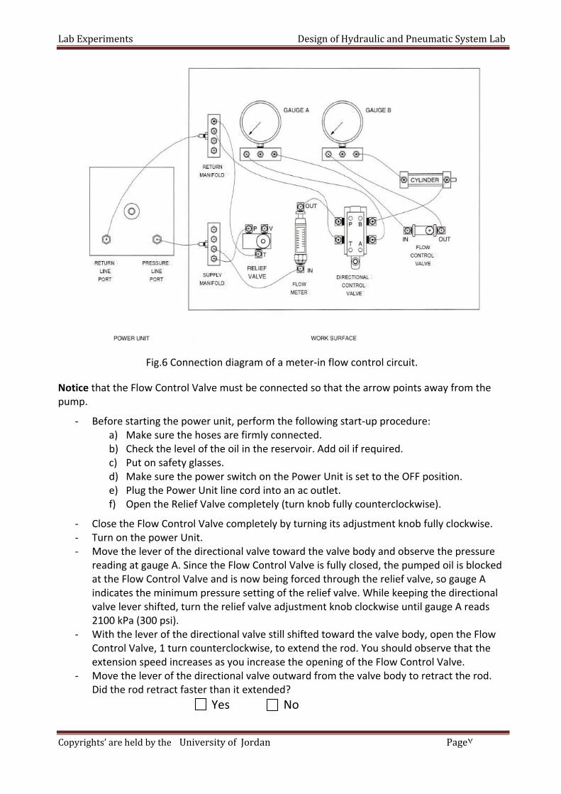
Fig.6 Connection diagram of a meter-in flow control circuit.
Notice that the Flow Control Valve must be connected so that the arrow points away from the pump.
- Before starting the power unit, perform the following start-up procedure: a) Make sure the hoses are firmly connected. b) Check the level of the oil in the reservoir. Add oil if required. c) Put on safety glasses. d) Make sure the power switch on the Power Unit is set to the OFF position. e) Plug the Power Unit line cord into an ac outlet. f) Open the Relief Valve completely (turn knob fully counterclockwise).
- Close the Flow Control Valve completely by turning its adjustment knob fully clockwise. - Turn on the power Unit. - Move the lever of the directional valve toward the valve body and observe the pressure
reading at gauge A. Since the Flow Control Valve is fully closed, the pumped oil is blocked at the Flow Control Valve and is now being forced through the relief valve, so gauge A indicates the minimum pressure setting of the relief valve. While keeping the directional valve lever shifted, turn the relief valve adjustment knob clockwise until gauge A reads 2100 kPa (300 psi).
- With the lever of the directional valve still shifted toward the valve body, open the Flow Control Valve, 1 turn counterclockwise, to extend the rod. You should observe that the extension speed increases as you increase the opening of the Flow Control Valve.
- Move the lever of the directional valve outward from the valve body to retract the rod. Did the rod retract faster than it extended?
Yes No

Lab Experiments Design of Hydraulic and Pneumatic System Lab
8Page University of Jordan Copyrights’ are held by the
- Move the lever of the directional valve toward the valve body to extend the cylinder rod. As the rod extends, close the Flow Control Valve completely by turning its adjustment knob fully clockwise. Does the Flow Control Valve provide direct control of the rod speed?
Yes No
- Retract the rod by moving the lever of the directional valve outward from the valve body. Observe that the rod still retracts at full speed even though the Flow control Valve is completely closed. Explain why.
- Open the flow control valve 1 turn counter clockwise. - Now adjust the Flow Control Valve to 1.5 I/min. To do so, move the lever of the
directional valve toward the valve body to extend the cylinder rod. As the cylinder extends, observe the Flow meter reading. Adjust the Flow Control Valve so that the Flow meter reads 1.5 I/min, then retract the rod. Accurate adjustment may require that the cylinder be extended and retracted several times.
Note: The trainer Flow meter provides a "Ipm" reading. Lpm means l/min, that is, "liters per minute".
- Measure the time required for the rod to extend fully using a stopwatch. Record this value in Table 1 under "ACTUAL". Also record the readings of gauges A and B while the rod is extending. When you have finished, retract the rod.
Flow rate to cylinder
Actual extension time
Gauge A Gauge B ΔP
(Gauge A – Gauge B)
1.5 I/min
2.0 I/min
2.5 I/min
Table 1 Meter-in flow control circuit data
- Repeat last two steps for other flow rate in Table 1. - Turn off the Power Unit. Open the Relief Valve completely by turning its .adjustment knob
fully counter clockwise. - Does the rod speed increase or decrease as the flow rate decrease?
- According to Table 1, does the pressure drop across the valve increase or decrease as the opening of the valve is increased? Why?

Lab Experiments Design of Hydraulic and Pneumatic System Lab
9Page University of Jordan Copyrights’ are held by the
Meter-out flow control circuit: In the second part of the exercise, you used meter-out control to change the cylinder
extension speed. Connect the circuit shown in Figures 7 and 8. This circuit meters the oil flow going out of
the pump.
Fig.7 Schematic diagram of a meter-out flow control circuit.
Fig.8 Connection diagram of a meter-out flow control circuit.
Notice that the Flow Control Valve must be connected so that the arrow points away from the pump.

Lab Experiments Design of Hydraulic and Pneumatic System Lab
10Page University of Jordan Copyrights’ are held by the
- Close the Flow Control Valve completely by turning its adjustment knob fully clockwise. - Turn on the power unit. - Move the lever of the directional valve outward from the valve body to retract the
cylinder rod completely. With the cylinder rod fully retracted, all the oil from the pump now flows through the Relief Valve and gauge B indicates the minimum pressure setting of the Relief Valve. While keeping the directional valve lever shifted, turn the Relief Valve adjustment knob clockwise until gauge Breads 2100 kPa (300 psi).
- Move the lever of the directional valve toward the valve body to extend the cylinder rod. As the rod extends, open the Flow Control Valve 1 turn counterclockwise. You should observe that the extension speed of the rod increases as you increase the Flow Control Valve opening. Retract the rod.
- Move the lever of the directional valve toward the valve body to extend the cylinder rod. As the rod extends, close the Flow Control Valve completely by turning its adjustment knob fully clockwise. Does the Flow Control Valve provide direct control of the rod speed?
Yes No
- Retract the rod. Does the setting of the Flow Control Valve have an effect on the retraction speed?
Yes No
- Adjust the Flow Control Valve so that the Flow meter reads 1.5 I/min as the rod extends, then retract the rod.
- Measure the extension time of the cylinder rod. Record this value in Table 2 under
"Extension". Also record the readings of gauges A and B while the rod is extending.
Flow rate to cylinder
Actual extension time
Gauge A Gauge B ΔP
(Gauge A – Gauge B)
1.5 I/min
2.0 I/min
2.5 I/min
Table 2 Meter-out flow control circuit data
- Repeat last two steps for other flow rate in T able 2. - Turn off the Power Unit. Open the Relief Valve completely by turning its .adjustment knob
fully counter clockwise. - According to Table 2, does the pressure drop across the valve increase or decrease as the
opening of the valve is increased? Why?
- Are the pressure drops in Table 2 for a meter-out circuit similar to the pressure drops in Table 1 for a meter-in circuit? Why?

Lab Experiments Design of Hydraulic and Pneumatic System Lab
11Page University of Jordan Copyrights’ are held by the
In this experiment, you will verify the formula F=PXA by measuring the compression force of cylinder, then you will demonstrate what happens when equal pressure is applied to both sides of a piston. PROCEDURE Connect the circuit shown in Figure 9, 10. Use the 2.54-cm (1-in) bore cylinder.
Fig. 9 Schematic diagram of Applying equal pressure on both sides of a piston.
Fig.10 Connection diagram of Applying equal pressure on both sides of a piston.
Part four: Pressure and Force

Lab Experiments Design of Hydraulic and Pneumatic System Lab
12Page University of Jordan Copyrights’ are held by the
- Examine the circuit of Figure 9. Predict which side of the piston will develop the most force.
- What do you think will happen to the cylinder rod?
- - Turn on the power unit. - Turn the Relief Valve adjustment knob clockwise until the circuit pressure at gauge A
equals 2100 kPa (300 psi). - While observing the cylinder rod, move the lever of the directional valve toward the valve
body so that the pumped oil is directed toward both sides of the cylinder piston. In which direction does the rod move? Why?
- Turn off the Power Unit. Open the relief valve completely (turn knob fully
counterclockwise) .

Lab Experiments Design of Hydraulic and Pneumatic System Lab
13Page University of Jordan Copyrights’ are held by the
Date:
Section:
Group's Names:
1-
2-
3-
4-
5-
Q1: Study the graphic diagram shown below and identify each of the lettered symbols.
A. --------------------------------
B. --------------------------------
C. --------------------------------
D. --------------------------------
E. --------------------------------
F. --------------------------------
G. --------------------------------
H. --------------------------------
University Of Jordan
Faculty of Engineering & Technology
Mechanical Engineering Department
Design of Hydraulic & Pneumatic System Lab
Experiments No.4
Introduction to Hydraulic Trainer
In class Lab Report
Part one: Identify the Hydraulic Trainer Components

Lab Experiments Design of Hydraulic and Pneumatic System Lab
14Page University of Jordan Copyrights’ are held by the
Q1: What is the purpose of a relief valve?
Q2: What might happen to a hydraulic system if the tank port of the relief valve is not connected to the power unit return line port? Q3: In the circuit of Figure below, what will be the pressure reading of gauge A during cylinder extension and when the cylinder is fully extended if the relief valve pressure setting is changed from 3400 kPa (500 psi) to 6900 kPa (1000 psi)?
Note: The pressure required to extend the cylinder rod is 600 kPa (85 psi).
Part two: Limiting System Pressure

Lab Experiments Design of Hydraulic and Pneumatic System Lab
15Page University of Jordan Copyrights’ are held by the
Q1: Find two ways to decrease the speed at which a cylinder rod extends or retracts. Q2: What flow rate is required to make a 10.16 cm bore X 3.81 cm rod X 30.48 cm stroke cylinder extend in 6 second? Q3: What type of metering circuit is used to control cylinders having a load that resists to the pump delivery, as cylinders raising a load? Q4. What type of metering circuit is used to slow down cylinders having a load that tends to run away, as cylinders lowering a load?
Q1. How much pressure must be applied to the cap end of a 2.54-cm (1-in) bore cylinder in order to compress a spring 5.08 cm (2 in), if the spring rate is728 N/cm (416 Ib/in)?
Part three: Flow rate
Part four: Pressure and Force

Lab Experiments Design of Hydraulic and Pneumatic System Lab
16Page University of Jordan Copyrights’ are held by the
Q2. In the circuit of Fig. 11(a), what will be the pressure at gauge B if the pressure at gauge A pressure is raised to 3500 kPa (500 psi)?
Q3. In the circuit of Fig.11 (b), what will be the pressure at gauge B if the pressure at gauge A pressure is raised to 3500 kPa (500 psi)?
(a) Pressure applied on full piston area. (b) Pressure applied on annular piston area.
Figure 11 Determining pressure distributions in a cylinder

Objective: This exercises helps to understand sequential controls and provides practical knowledge of setting up and commissioning a control system with two pneumatic drives.
Pre‐Lab: the required pneumatic circuit diagrams using the FlwidSIM; show
the whole connections and components required for each circuit.
In the lab: Build your designs and verify their operation. sure that the pressure is 4 bars and is connected correctly. Double check your connections before switching the compressor on.
Task 1: Pressing device with time control Learning objectives: Upon the completion of this task, the student will be • Familiar with the set‐up and mode of operation of a time delay valve normally closed. • Able to recognize and sketch the time delay valve. • Able to choose different pneumatic components according to the given conditions. Problem Description: A double acting cylinder is used to press glued components together. Upon operation of a push button, the clamping cylinder extends as shown in Fig. 5.1 below. Once the fully advanced position is reached, the cylinder is to remain for a time of T = 6 seconds and then retract to the initial position automatically. The cylinder retraction is to be adjustable. A new start cycle is only possible after the cylinder has fully retracted.
University Of Jordan
Faculty of Engineering & Technology
Mechatronics Engineering Department
Design of Hydraulic & Pneumatic System Lab
Experiments No.5
Sequential control of a 2 double acting cylinder
Part I: Time delay valve and sequence control systems
Pre‐Lab

LabExper
Copyrights
Requirem1. Dr2. Sim3. As
Pneumati
riments
s’areheldby
ments: raw pneumamulate the ssemble the
ic circuit dia
ytheUnivers
atic circuit dcircuit usine circuit pra
agram
sityofJordan
Fig. 5.
diagram usig FluidSIM ctically and
D
n,Prepared
1 Positiona
ing the spacsoftware. d check its o
esignofHyd
Eng.Ra by:
l sketch
ce provided
operation.
draulicand
ashaNoufal
d below.
PneumaticS
SystemLab
2Page

LabExper
Copyrights
IntroductIn many athe pistonThis is carthree porcontrol vaThe exhaushown in 3.2 Way oCompressvalve fromWhen preFig. (5.3.cto the cyl
Task 2: Ed Learning oUpon the • Familiar way valv• Able to • Able to
riments
s’areheldby
tion to Quicapplicationsn speed durrried out byts: supply palve). The oust port 3 isthe Fig. (5.2
of operationsed air flowm port (1) toessure at poc). In order tinder’s supp
Fig. 5.
dge folding
objectives: completionr with the seve. recognize aconstruct a
ytheUnivers
ck Exhaust vs especially ring retractiy incorporatport 1, is conutput port s left open t2).
n s from the do port (2). Eort 1 drops, to implemeply port.
.2. ISO sym exhaust va
device
n of this taset‐up and m
and sketch ta complete c
P
sityofJordan
valve: with single on of the cyting a quicknnected to 2 of this valto the atmo
directionalExhaust porexhaust flont optimize
bol of quickalve
sk, the studemode of ope
the Two Precircuit with
Part II: Q
D
n,Prepared
acting cylinylinder to sexhaust vathe output lve is directosphere The
control valvt 3 is closedow occurs fred quick exh
k
ents will beeration of a
essure Valvedifferent co
Quick Exh
esignofHyd
Eng.Ra by:
nders, it is aave the cyclve . The quof the finally fitted on e I.S.O. symb
ve to the cyd at this timrom port (2haust, the v
Fig.5.3. Sc qu
normally c
e. onditions.
haust valv
draulicand
ashaNoufal
a common ple time. uick exhaustl control eleto the worbol for quic
ylinder via tme. ) to port (3)valve must b
chematic diuick exhaust
losed 3/2‐ w
ve
PneumaticS
practice to
t valve has eement (direking port ofck exhaust v
he quick ex
) as illustratbe connecte
iagram of tht valve
way valve a
SystemLab
3Page
increase
essentially ctional f cylinder. valve is
haust
ted in ed directly
he
nd 5/2

LabExper
Copyrights
problemsIn order tmachine ttime. Opeto fall dowbutton is position (
Requirem
1. Drth
2. Sim3. As
an
riments
s’areheldby
s Descriptioo maintain that is showeration of thwn rapidly (released, ththe backwa
ments:
raw pneumae space promulate the ssemble thend check its
ytheUnivers
on: a safe operwn in Fig. (5he two push(forward strhe double aard stroke o
atic circuit dovided belowcircuit usine circuit praoperation.
sityofJordan
rating enviro.4) has to bh button varoke of the acting cylindof the doubl
diagram usiw. g FluidSIM ctically
D
n,Prepared
onment forbe operatedlves causesdouble actider (1A) slowe acting cyl
ing
software.
esignofHyd
Eng.Ra by:
r the formin by two pus the forminng cylinderwly should linder shou
draulicand
ashaNoufal
ng machine sh button vag tool of anr). If both orslowly retuld be slow).
Fig. 5.4 P
PneumaticS
operator, talves at then edge‐foldir even just orn to the in.
ositional sk
SystemLab
4Page
he forming e same ng deviceone push itial
ketch

LabExper
Copyrights
Task 3: Pn Problem D A flap confrom a cotwo differBy pressinopened aAfter releclosed aga
Requirem1. Dr2. Sim3. As
riments
s’areheldby
neumatics O
Description
ntrol is usedntainer. Thrent locationg any one nd the granasing the pain as show
ments: raw pneumamulate the ssemble the
ytheUnivers
OR circuit
n:
d to empty ge machine sns using twof two pushnular materushbutton v
wn in the Fig
atic circuit dcircuit usine circuit pra
sityofJordan
granular mashould be o
wo push butthbutton valial is emptievalve the flag. 5.5 below
diagram usig FluidSIM ctically and
Part III:
D
n,Prepared
aterial operated froton valves. ves the flaped from its ap control iw.
ing the spacsoftware. d check its o
: Logic fu
esignofHyd
Eng.Ra by:
om p is container. s
ce provided
operation.
unctions
draulicand
ashaNoufal
Fig
d below.
PneumaticS
g. 5.5 Positio
SystemLab
5Page
onal sketch

LabExper
Copyrights
Task 4: Pn ObjectiveUpon the using an p Problem dParts are shown betrack gravit has to r Hint: A im
Required
1‐ Dr2‐ Te3‐ Co
riments
s’areheldby
neumatics l
es: competitiopneumatic l
descriptionto be pusheelow in Fig.5vity feed mareturn to its
mpulse 5/2 D
procedure
raw the pneest the circuonstruct the
Part I
ytheUnivers
latching circ
on of this talatching circ
n: ed away fro5.6. By pressagazine by a start positi
DCV spring
s:
eumatic circuit functionse circuit on t
IV: Basic
sityofJordan
cuit
sk, the studcuit.
om a multi‐tsing a pusha slide. Afteion.
return is to
cuit using ths against anthe worksta
c Circuit w
D
n,Prepared
dent should
track gravitybutton switer the slide h
o be used fo
Fig. 5
he FluidSimny errors or ation
with Pne
esignofHyd
Eng.Ra by:
be able to
y feed magatch the parthas reached
or flow cont
5.6
software mistakes.
eumatic l
draulicand
ashaNoufal
control an
azine into ats are pushed the forwa
trol.
latching
PneumaticS
pneumatic
a clamping ded out of thrd end posi
circuit
SystemLab
6Page
system by
device as he multi‐ition

LabExper
Copyrights
‐ Bufu
‐ No
S1 cy S3 cy
‐ Dr No
riments
s’areheldby
uild your denction diag
ote
1 and S2: 3/ylinder one 3 and S4 : 3/ylinder two
rawing the c
ote : Suppo
Part
ytheUnivers
esign ( Pneuram in Fig.5
/2 direction . /2 direction.
circuit diagr
se initial po
V: Sequ
sityofJordan
matic circu5.7
al control v
nal control v
ram with sy
osition for tw
uential co
D
n,Prepared
it diagram )
valve , with
valve , with
ymbols and
wo cylinder
ontrol of
esignofHyd
Eng.Ra by:
) to comple
roller , to in
roller , to i
port symbo
r in retract p
f a doubl
draulicand
ashaNoufal
ete the task
nduction of
nduction of
ols.
position.
e cylinde
PneumaticS
k description
position fo
f position fo
er A
SystemLab
7Page
n in
r
or

LabExper
Copyrights
Pn
riments
s’areheldby
neumatic ci
ytheUnivers
Fig
rcuit diagra
sityofJordan
g.5.7 Functio
am
D
n,Prepared
on diagram
esignofHyd
Eng.Ra by:
(stroke‐tim
draulicand
ashaNoufal
me diagram)
PneumaticS
)
SystemLab
8Page

LabExper
Copyrights
Aim:
This exercup a contUpon the
Problem dIn the tranto a proceto the propiston rod
riments
s’areheldby
cise helps torol system wcompletion
Explain the
descriptionnsfer statioessing statioocessing stad of cylinde
Part
ytheUnivers
o understanwith two pnn of this tas
e displacem
n: n shown beon. The blocation by cylir 2A has rea
t VI: Seq
sityofJordan
nd sequentineumatic drsk, the stude
ment step di
elow in Fig. cks are pushnder 2A. Thached the r
uential c
D
n,Prepared
al controls rives. ent should b
iagrams
5.8, the blohed out of the piston roretracted en
Fig.5.8
control o
esignofHyd
Eng.Ra by:
and provide
be able to
ocks are to bthe magazinod of cylindend position.
of a doub
draulicand
ashaNoufal
es practical
be transferrne by cylinder 1A may o
ble cylind
PneumaticS
knowledge
red from a mder 1A and tonly return
der B
SystemLab
9Page
e of setting
magazine transferred when the

LabExper
Copyrights
riments
s’areheldby
ytheUnivers
sityofJordan
D
n,Prepared
esignofHyd
Eng.Rasha
draulicand
aNoufal
PneumaticS
P
SystemLab
10Pageby:
:

LabExperimentsDesignofHydraulicandPneumaticSystemLab
11Page Eng.RashaNoufal Copyrights’areheldbytheUniversityofJordan,Preparedby:
‐ Design the functional diagram (stroke‐time diagram) for the cylinder and the 5/2
directional control valve.

LabExperimentsDesignofHydraulicandPneumaticSystemLab
1Page Eng.RashaNoufal Copyrights’areheldbytheUniversityofJordan,Preparedby:
Objective: This exercises helps to understand sequential controls and provides practical knowledge of setting up and commissioning a control system with two pneumatic drives.
Pre‐Lab: the required pneumatic circuit diagrams using the FluidSIM; show
the whole connections and components required for each circuit.
In the lab: Build your designs and verify their operation. sure that the pressure is 4 bars and is connected correctly. Double check your connections before switching the compressor on.
Task:
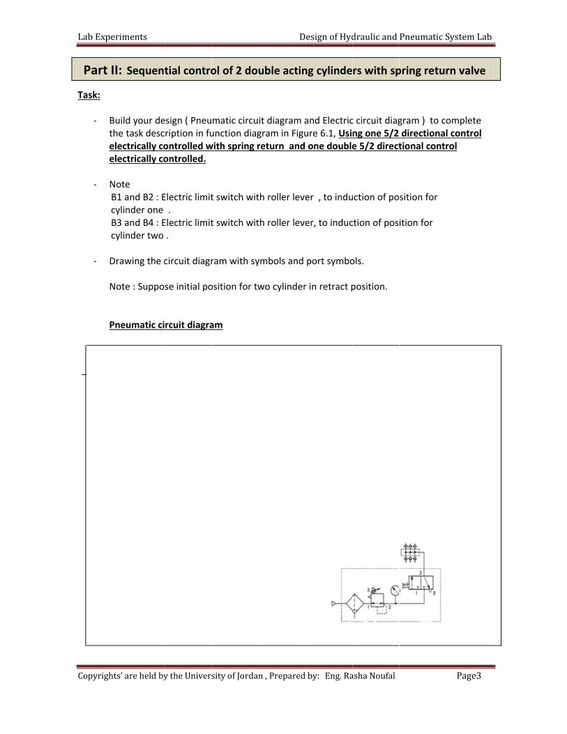
‐ Build your design ( Pneumatic circuit diagram and Electric circuit diagram ) to complete the task description in function diagram in Figure 6.1
‐ Note
B1 and B2 : Electric limit switch with roller lever , to induction of position for cylinder one . B3 and B4 : Electric limit switch with roller lever, to induction of position for cylinder two .
‐ Drawing the circuit diagram with symbols and port symbols. Note : Suppose initial position for two cylinder in retract position.
University Of Jordan
Faculty of Engineering & Technology
Mechatronics Engineering Department
Design of Hydraulic & Pneumatic System Lab
Experiments No.6
Electro pneumatics Sequential control of a 2 double acting cylinder
Part I: Electro pneumatics Sequential control of 2 double acting cylinders A
Pre‐Lab

LabExper
Copyrights
Pn
riments
s’areheldby
neumatic ci
ytheUnivers
Figur
rcuit diagra
sityofJordan
re 6.1: Func
am
D
n,Prepared
ction diagra
esignofHyd
Eng.Ra by:
am (stroke‐t
draulicand
ashaNoufal
time diagra
PneumaticS
m)
SystemLab
2Page
LabExper
Copyrights
Task:
‐ Butheleele
‐ No
B1 cy B3 cy
‐ Dr No Pn
Part II
riments
s’areheldby
uild your dee task descectrically coectrically co
ote 1 and B2 : Eylinder one 3 and B4 : Eylinder two
rawing the c
ote : Suppo
neumatic ci
: Sequent
ytheUnivers
esign ( Pneuription in fuontrolled wontrolled.
Electric limit . Electric limit.
circuit diagr
se initial po
rcuit diagra
tial contro
sityofJordan
matic circuunction diagwith spring r
t switch wit
t switch wit
ram with sy
osition for tw
am
ol of 2 dou
D
n,Prepared
it diagram agram in Figureturn and
th roller leve
th roller leve
ymbols and
wo cylinder
uble actin
esignofHyd
Eng.Ra by:
and Electricure 6.1, Usione double
er , to indu
er, to induc
port symbo
r in retract p
ng cylinde
draulicand
ashaNoufal
c circuit diagng one 5/2 e 5/2 direct
uction of po
ction of pos
ols.
position.
rs with sp
PneumaticS
gram ) to codirectionaltional contr
sition for
ition for
pring retur
SystemLab
3Page
omplete l control rol
rn valve

LabExper
Copyrights
Task: ‐ Bu
thele
‐ No
B1 cy B3 cy
‐ Dr No Pn
Part I
riments
s’areheldby
uild your dee task descectrically co
ote 1 and B2 : Eylinder one 3 and B4 : Eylinder two
rawing the c
ote : Suppo
neumatic ci
III: Seque
ytheUnivers
esign ( Pneuription in fuontrolled w
Electric limit . Electric limit.
circuit diagr
se initial po
rcuit diagra
ential cont
sityofJordan
matic circuunction diagwith spring r
t switch wit
t switch wit
ram with sy
osition for tw
am
trol of 2 d
D
n,Prepared
it diagram agram in Figureturn .
th roller leve
th roller leve
ymbols and
wo cylinder
double act
esignofHyd
Eng.Ra by:
and Electricure 6.1, Usi
er , to indu
er, to induc
port symbo
r in retract p
ting cylind
draulicand
ashaNoufal
c circuit diagng two 5/2
uction of po
ction of pos
ols.
position.
ders with t
PneumaticS
gram ) to co directiona
sition for
ition for
two sprin
SystemLab
4Page
omplete l control
g return

LabExper
Copyrights
Task:
‐ Buthele
‐ No
B1 cy B3 cy
‐ Dr No
Pa
riments
s’areheldby
uild your dee task descectrically co
ote
1 and B2 : Eylinder one 3 and B4 : Eylinder two
rawing the c
ote : ‐ Supp ‐ The w direc
art IV: Ele
ytheUnivers
esign ( Pneuription in fuontrolled .
Electric limit. Electric limit.
circuit diagr
pose initial pworking spections.
Figur
ectro pneu
sityofJordan
matic circuunction diag
t switch wit
t switch wit
ram with sy
position foreed of both
re 6.2: Func
umatics Se
D
n,Prepared
it diagram agram in Figu
th roller leve
th roller leve
ymbols and
r two cylind cylinders s
ction diagra
equential
esignofHyd
Eng.Ra by:
and Electricure 6.2 , Usi
er, to induc
er, to induc
port symbo
er in retracshould be in
am (stroke‐t
l control o
draulicand
ashaNoufal
c circuit diaging 5/2 dire
ction of pos
ction of pos
ols.
t position.nfinitely adj
time diagra
of a doubl
PneumaticS
gram ) to coectional con
ition for
ition for
ustable in b
m)
e cylinder
SystemLab
5Page
omplete ntrol
both
r B

LabExper
Copyrights
Pn
riments
s’areheldby
neumatic ci
ytheUnivers
rcuit diagra
sityofJordan
am
D
n,Prepared
esignofHyd
Eng.Ra by:
draulicand
ashaNoufal
PneumaticS
SystemLab
6Page

LabExper
Copyrights
Task:
‐ Butheleele
‐ No
B1 cy B3 cy
‐ Dr No Pn
Part V
riments
s’areheldby
uild your dee task descectrically coectrically co
ote 1 and B2 : Eylinder one 3 and B4 : Eylinder two
rawing the c
ote : ‐ Supp ‐ The w direc
neumatic ci
: Electropne
ytheUnivers
esign ( Pneuription in fuontrolled wontrolled.
Electric limit. Electric limit.
circuit diagr
pose initial pworking spections
rcuit diagra
eumatics Seq
sityofJordan
matic circuunction diagwith spring r
t switch wit
t switch wit
ram with sy
position foreed of both
am
quential con
D
n,Prepared
it diagram agram in Figureturn and
th roller leve
th roller leve
ymbols and
r two cylind cylinders s
ntrol of 2 dou
esignofHyd
Eng.Ra by:
and Electricure 6.2 , Usone double
er, to induc
er, to induc
port symbo
er in retracshould be in
uble acting c
draulicand
ashaNoufal
c circuit diagsing one 5/2e 5/2 direct
ction of pos
ction of pos
ols.
t position.nfinitely adj
cylinders wit
PneumaticS
gram ) to co2 directionational contr
ition for
ition for
ustable in b
th spring ret
SystemLab
7Page
omplete al control rol
both
urn valves

LabExper
Copyrights
Task: ‐ Bu
thele
‐ No B1 cy B3 cy
‐ Dr No Pn
Part V
riments
s’areheldby
uild your dee task descectrically co
ote 1 and B2 : Eylinder one 3 and B4 : Eylinder two
rawing the c
ote : ‐ Supp ‐ The w direc
neumatic ci
VI: Electro p
ytheUnivers
esign ( Pneuription in fuontrolled w
Electric limit. Electric limit.
circuit diagr
pose initial pworking spections
rcuit diagra
pneumatics S
sityofJordan
matic circuunction diagwith spring .
t switch wit
t switch wit
ram with sy
position foreed of both
am
Sequential co
D
n,Prepared
it diagram agram in Figu.
th roller leve
th roller leve
ymbols and
r two cylind cylinders s
ontrol of 2 d
esignofHyd
Eng.Ra by:
and Electricure 6.2 , Us
er, to induc
er, to induc
port symbo
er in retracshould be in
double acting
draulicand
ashaNoufal
c circuit diagsing two 5/
ction of pos
ction of pos
ols.
t position.nfinitely adj
g cylinders w
PneumaticS
gram ) to co/2 direction
ition for
ition for
ustable in b
with two spr
SystemLab
8Page
omplete nal control
both
ing return

Objective: Students will be able to describe the operation of a regenerative circuit, describe the effect of regeneration on cylinder speed and describe the effect of regeneration on cylinder force. The primary purpose of regenerative circuits is to provide rapid extension speeds with a minimum pump output flow. Regeneration is accomplished by sending the oil which flows out of the rod end of a cylinder back into the cap end of this cylinder.
In this part of the exercise, you will determine the effect of regeneration on the extension time of a cylinder. To do so, you will measure the time required for a cylinder to extend in both regenerative and normal modes of operation. You will then compare the results obtained in each mode. In this exercise, you learned that a regenerative circuit increases the extension speed of a cylinder. You caused a cylinder to extend more rapidly by applying equal pressures to both sides of the piston. The extension time was reduced by a factor equal to the ratio of the full piston area to the rod area, Af / Arod.. Cylinder speed during regeneration: S.I Units:
Extension speed (cm/s) = Fow rate (l/min) × 1000 Rod area(cm2) × 60
English Units: Extension speed (in/s) = Fow rate (gal/min) × 231
Rod area(in2) × 60
University Of Jordan
Faculty of Engineering & Technology
Mechatronics Engineering Department
Design of Hydraulic & Pneumatic System Lab
Experiments No.7
Regenerative and Parallel Circuits
Introduction
Part I: Effect of regeneration on cylinder extension time

LabExper
Copyrights
The formucomplete The formu S.I Units:
English Un
‐ Connect reduce t Note: Do later in th
riments
s’areheldby
ula for calcu its stroke isula is as foll
nits:
t the circuit he flow into
not conneche exercise.
Univer ythe
ulating the as the formulows:
Extension t
Extension t
shown in Fo the circuit
ct the Loadi
Fi
rsityofJord
amount of tula for exten
ime (s) = Rod
time (s) = Ro
igure 1. In tt so the cyli
ng Device t
g.1 Cylinde
D
dan
time requirnsion speed
d area (cm2)
Flow r
od area (in2) Flow r
this circuit, nder speed
o the cylind
r in a regen
esignofHyd
red for a cyld divided int
× 60 × Strorate(l/min) ×
× 60 × Strorate(gal/min) ×
the Flow Cod is easier to
der yet. The
nerative circ
draulicand
inder in regto the strok
oke length (c1000
oke length (in× 231
ontrol Valveo time.
e Loading De
cuit.
PneumaticS
generation tke length.
cm)
n)
e will be use
evice will be
SystemLab
2Page
to
ed to
e used

LabExperimentsDesignofHydraulicandPneumaticSystemLab
3Page UniversityofJordan Copyrights’areheldbythe
‐ Before starting the power unit, perform the following start‐up procedure. a. Make sure the hoses are firmly connected. b. Check the level of the oil in the reservoir. Add oil if required. c. Put on safety glasses. d. Make sure the power switch on the Power Unit is set to the OFF position. e. Plug the Power Unit line cord into an ac outlet. f. Open the Relief Valve completely (turn knob fully counterclockwise). ‐ Open the flow control valve completely (turn knob fully counterclockwise ). ‐ Turn on the power Unit. ‐ With the directional valve lever in the center position, the pump flow is blocked at the rod end of the cylinder, and gauge B indicates the Relief Valve pressure setting. Turn the Relief Valve adjustment knob clockwise until the circuit pressure at gauge B is 2100 kPa (300 psi). ‐ Move the lever of the directional valve toward the valve body to extend the cylinder and adjust the Flow Control Valve so that the Flowmeter reads 1.5 I/min [0.4 gal(US)/min] during cylinder extension, then retract the cylinder. Accurate adjustment may require that the cylinder be extended and retracted several times.
‐ Extend the cylinder and note the extension time and the pressure readings at gauges A and B as the cylinder extends. Record these in the "Regenerative" row of Table 1.
Circuit Condition Extension Time Extension Pressures
Gauge A Gauge B
Regenerative
Normal
Table 1. Cylinder data in regenerative and normal modes
‐ Retract the cylinder. ‐ Turn on the power unit. Open The relief valve completely (turn knob fully counterclockwise).
‐ Change your regenerative circuit into a normal (non‐regenerative) circuit. To do so, disconnect the rod end of the cylinder from the 4‐port manifold installed on port P of the directional valve, then connect the rod end to port B of the directional valve, as Figure 2 shows.

LabExper
Copyrights
Note: Do later in th
‐ Turn on ‐ Move th keeping pressure direction ‐ Turn Mo adjust th cylinder be exten ‐ Extend t the cylin ‐ Retract t ‐ Turn off
riments
s’areheldby
not conneche exercise.
the Power
he lever of tthe valve lee at gauge Anal valve ou
ove the levehe Flow Conextension, nded and re
the cylinderder extend
the cylinder
the power
Univer ythe
Fig.2 Cyli
ct the Loadi
Unit.
he directionever shiftedA is 21 00 kPutward from
er of the dirntrol Valve sthen retracetracted sev
r and note ts. Record th
r.
unit. Open
rsityofJord
inder in a n
ng Device t
nal valve to, turn the RPa (300 psi)m the valve b
ectional valso that the ct the cylindveral times.
he extensiohese in the
The relief v
D
dan
ormal (non
o the cylind
oward the vaRelief Valve. Retract thbody.
lve toward Flowmeter der. Accurat
on time and"Normal" ro
valve compl
esignofHyd
regenerativ
der yet. The
alve body toadjustmente cylinder b
the valve breads 1.5 I/te adjustme
d the pressuow of Table
letely (turn
draulicand
ve circuit).
e Loading De
o extend tht knob clockby moving t
ody to exte/min [0.4 gaent may req
ure readingse 1.
knob fully c
PneumaticS
evice will be
he cylinder fkwise until he lever of
end the cylinal(US)/min] uire that th
s at gauges
countercloc
SystemLab
4Page
e used
fully. While the circuitthe
nder and during
he cylinder
A and B as
ckwise).

LabExperimentsDesignofHydraulicandPneumaticSystemLab
5Page UniversityofJordan Copyrights’areheldbythe
‐ According to Table 3‐8, is the extension time observed in regenerative mode shorter than that observed in normal mode? Why? ‐ Calculate the theoretical extension time of the 2.54‐cm (1‐in) bore x 1.59‐cm (0.625‐in) rod x 10.16‐cm (4‐in) stroke cylinder in regeneration when the flow rate is 1.51/min [0.4 gal(US)/min]. Then, compare your result with the actual extension time recorded in Table 1. Are these values approximately equal?

LabExperimentsDesignofHydraulicandPneumaticSystemLab
6Page UniversityofJordan Copyrights’areheldbythe
In the second part of the exercise, you will determine the effect of regeneration on the force output of a cylinder. To do so, you will measure the force output of a cylinder in both regenerative and normal modes of operation. You will then compare the results obtained in each mode. Cylinder force during regeneration: the force generated by the cylinder during extension is equal to the circuit pressure multiplied by the rod area. In equation form: S.I Units:
Force (N) = Pressure (Kpa) × Rod area (cm2)
English Units:
Force (lb) = Pressure (psi) × Rod area (in2) ‐ Change your circuit into a regenerative circuit. To do so, disconnect the rod end of the cylinder from port B of the directional valve, then connect the rod end to the 4‐port manifold installed on port P of the directional valve, as shown in Figure 1. ‐ Disconnect the 2.54‐cm (1‐in) bore cylinder from the circuit. Remove the cylinder from its adapter by unscrewing its retaining ring. Make sure the cylinder tip (bullet) is removed from the cylinder rod end. Screw the cylinder into the Loading Device. Then, reconnect the cylinder into the circuit as shown in‐Figure 1. ‐ Clip the NEWTON/LBF‐graduated ruler to the Loading Device, and align the "0" mark with the colored line on the load piston. ‐ Open the flow control valve completely (turn knob fully counterclockwise). ‐ Turn on the power unit. ‐ Move the lever of the directional valve toward the valve body and turn the Relief Valve adjustment knob clockwise until the circuit pressure at gauge A is 4200 kPa (600 psi), then turn the knob counterclockwise to decrease the circuit pressure until gauge A reads 3500 kPa (500 psi). Release the valve lever. ‐ Note and record the force reading on the Loading Device in the "Regenerative" row of Table 2.
Circuit Condition Cylinder force output
Regenerative
Normal
Table 2. Effect of regeneration on cylinder force.
Part II: Effect of regeneration on cylinder force output

LabExperimentsDesignofHydraulicandPneumaticSystemLab
7Page UniversityofJordan Copyrights’areheldbythe
‐ Retract the cylinder, then turn off the Power Unit. Open the Relief Valve completely (turn knob fully counterclockwise). ‐ Change your regenerative circuit into a normal circuit. To do so, disconnect the rod end of the cylinder from the 4‐port manifold installed on port P of the directional valve, then connect the rod end to port B of the directional valve, as shown in Figure 2. ‐ Turn on the power unit. ‐ Move the lever of the directional valve toward the valve body and turn the Relief Valve adjustment knob clockwise until the circuit pressure at gauge A is 4200 kPa (600 psi), then turn the knob counterclockwise to decrease the circuit pressure until gauge A reads 3500 kPa (500 psi). Release the valve lever . ‐ Note and record the force reading on the Loading Device in the "Normal" row of Table 2. ‐ Retract the cylinder, then turn off the Power Unit. Open the Relief Valve completely (turn knob fully counterclockwise). ‐ According to Table 2, is the force observed in regeneration mode reduced from that observed in normal mode? Explain why. ‐ Calculate the theoretical force output of the 2.54‐cm (1‐in) bore x 1.59‐cm (O.625‐in) rod x 10.16‐cm (4‐in) stroke cylinder in regeneration. Then, compare your result with the actual force output recorded in Table 2. Are these values approximately equal? ‐ Disconnect the Power Unit line cord from the wall outlet, then disconnect all hoses. Wipe off any hydraulic oil residue. ‐ Remove all components from the work surface and wipe off any hydraulic oil residue. Return all components to their storage location. ‐ Clean up any hydraulic oil from the floor and from the trainer. Properly dispose of any paper towels and rags used to clean up oil.

LabExper
Copyrights
EXERCISE
‐ To‐ To‐ To
PROCEDU ‐ Connect
‐ Examineacts as a lunevenly cylinder. When thethe cap siresistancein) bore] mextend. T Predict wa heavy lo
riments
s’areheldby
OBJECTIVE
o describe to describe to synchroni
URE
t the circuit
e the circuit oading devloaded. The
e directionade of both e offered bymust counthe cylinder
hich cylindeoad on the l
Univer ythe
E
the operatiothe extensioize the exte
shown in F
Fig.3. Cylin
in Fig.3. Thvice on the le Flow Cont
l valve is shcylinders aty the Flow Ceract the rerequiring t
er will extenlarge cylind
Pa
rsityofJord
on of a paraon sequencension of pa
ig. 3.
nders in paralle
he cylindersarge cylindetrol Valve is
hifted to extt the same tControl Valvesistance ofhe lowest p
nd first wheer, and exp
art III: Cy
D
dan
allel circuit;e of parallearallel cylind
el with a heavy
are in paraer [3.81‐cms partially cl
tend the cyltime. The lave before it f the oil flowpressure to
en the Flow plain why.
ylinders i
esignofHyd
el cylinders ders using a
y load on the la
allel with eam (1.5‐in) bolosed to sim
linders, the arge cylindecan extendwing back tomove will e
Control Va
n Paralle
draulicand
having diffea flow contr
arge cylinder
ch other. Tore] only, somulate a hea
oil from ther must coud. The smallo the reservextend first.
lve is partia
el
PneumaticS
ering bore sol valve.
he Flow Coo the cylindeavy load on
e pump is dnteract the cylinder [2voir before .
ally closed t
SystemLab
8Page
sizes;
ntrol Valve ers are the large
directed to high .54‐cm (1‐it can
o simulate

LabExperimentsDesignofHydraulicandPneumaticSystemLab
9Page UniversityofJordan Copyrights’areheldbythe
‐ Before starting the Power Unit, perform the following start‐up procedure:
a. Make sure the hoses are firmly connected. b. Check the level of the oil in the reservoir. Add oil if required. c. Put on safety glasses. d. Make sure the power switch on the Power Unit is set to the OFF e. position. f. Plug the Power Unit line cord into an ac outlet. g. Open the Relief Valve completely (turn knob fully counterclockwise).
‐ Close the Flow Control Valve completely (turn knob fully clockwise), then open it ½ turn. ‐ Turn on the Power Unit. ‐ Turn the relief valve adjustment knob clockwise until the circuit pressure at gauge A is 2100 kPa (300 psi). ‐ Move the lever of the directional valve toward the valve body to extend the two cylinders and observe them as they extend. Which cylinder extended first? Why? ‐ Retract the cylinders. ‐ Turn off the Power Unit. Open the Relief Valve completely (turn knob fully counterclockwise).

LabExper
Copyrights
‐ Modify ysmall cylin
‐ Predict wsimulate a ‐ Close th ‐ Turn on ‐ Turn the(300 psi). ‐ Move thobserve t
Pa
riments
s’areheldby
your circuit nder [2.54‐c
which cylinda heavy loa
e Flow Cont
the Power
e Relief Valv
he lever of them as the
rt IV: Cyl
Univer ythe
connectioncm (1‐in) bo
Fig.4. Cylin
der will exted on the sm
trol Valve c
Unit.
ve adjustme
the directioy extend. W
linder sy
rsityofJord
ns in order tore], as Fig.4
nders in paralle
end first whmall cylinder
ompletely (
ent knob clo
onal valve toWhich cylind
ynchroniz
D
dan
to place the4. shows.
el with a heavy
hen the Flowr.
(turn knob f
ockwise unt
oward the vder extende
zation us
esignofHyd
e loading de
y load on the sm
w Control V
fully clockw
til the circui
valve body ted first? Wh
sing a Flo
draulicand
evice (Flow C
mall cylinder.
Valve is part
wise), then o
t pressure a
to extend thhy?
ow Contr
PneumaticS
Control Val
ially closed
open it ¼ tu
at gauge A i
he two cylin
rol Valve
SystemLab
10Page
ve) on the
to
rn.
is 2100 kPa
nders and
e

LabExperimentsDesignofHydraulicandPneumaticSystemLab
11Page UniversityofJordan Copyrights’areheldbythe
‐ Retract the cylinders. ‐ Adjust the setting of the Flow Control Valve so that both cylinders complete their full stroke at the same time during extension. Accurate adjustment may require that the cylinders be extended and retracted several times. ‐ Extend and retract the cylinders several times with the new Flow Control Valve setting. Do the cylinders remain synchronized?
Yes No
‐ Let the system run for about 15 minutes. Do not modify the Flow Control Valve setting. ‐ Extend and retract the cylinders several times. Did the cylinders stay in synchronization?
Yes No
‐ Does the Flow Control Valve have to be readjusted when the cylinders are operated over an extended period of time? Explain why ‐ Try to adjust the Flow Control Valve so that the small cylinder completes its extension approximately 2 seconds after the large cylinder completes its extension. Can the extension sequence of the cylinders be controlled in a parallel circuit? Explain. ‐ Make sure the cylinders are fully retracted, then turn off the Power Unit.Open the Relief Valve completely (turn knob fully counterclockwise). ‐ Disconnect the Power Unit line cord from the wall outlet, then disconnect all hoses. Wipe off any hydraulic oil residue. ‐ Remove all components from the work surface and wipe off any hydraulic oil residue. Return all components to their storage location. ‐ Clean up any hydraulic oil from the floor and from the trainer. Properly dispose of any paper towels and rags used to clean up oil.

LabExperimentsDesignofHydraulicandPneumaticSystemLab
12Page UniversityofJordan Copyrights’areheldbythe
Date:
Section:
Group's Names:
1‐
2‐
3‐
4‐
5‐
Q1: What is the regenerative circuit?
Q2: Would a cylinder extend more rapidly in a normal circuit or a regenerative circuit?
University Of Jordan
Faculty of Engineering & Technology
Mechatronics Engineering Department
Design of Hydraulic & Pneumatic System Lab
Experiments No.6
Regenerative Circuits
In class Lab Report
Part one: Effect of regeneration on cylinder extension time

LabExperimentsDesignofHydraulicandPneumaticSystemLab
13Page UniversityofJordan Copyrights’areheldbythe
Q1: Would a cylinder generate more force in a normal circuit or in a regenerative circuit? Q2: What happens to the extension speed and force generated in a regenerative circuit when the piston rod diameter is decreased? Q3: By which amount is the cylinder force output reduced in a regenerative circuit giving double the normal extension speed?
Part two: Effect of regeneration on cylinder force output

Objective: This exercises helps to understand sequential controls and provides Practical knowledge of setting up and commissioning a control system with two pneumatic drives.
Pre‐Lab: the required pneumatic circuit diagrams using the FlwidSIM; show the whole connections and components required for each circuit.
In the lab: Build your designs and verify their operation. sure that the pressure is 4 Bars and is connected correctly. Double check your connections before Switching the compressor on.
Build your design Pneumatic circuit diagram to complete the task description in function
diagram in Figure 8.1 ( A and B are double acting cylinders )
Fig. 8.1 Positional sketch
Requirements:
1. Draw pneumatic circuit diagram using the space provided below.
2. Simulate the circuit using FluidSIM software.
3. Assemble the circuit practically and check its operation.
A
B
University Of Jordan
Faculty of Engineering & Technology
Mechatronics Engineering Department
Design of Hydraulic & Pneumatic System Lab
Experiments No.8
Pneumatic sequential control of a 3 double acting cylinder
Part I: Sequential control of a two double cylinders
Pre‐Lab

LabExper
Copyrights
Pneuma
Build you
diagram
Require
1. Dr
2. Si
3. As
P
riments
s’areheldby
atic circui
ur design P
in Figure 8
ements:
raw pneum
mulate the
ssemble th
art II: Se
ytheUnivers
t diagram
Pneumatic
8.2 ( A , B
matic circui
e circuit us
e circuit pr
equentia
sityofJordan
m
circuit diag
and C are
t diagram
ing FluidSI
ractically a
l control
D
n,Prepared
gram to co
double act
using the
IM softwar
and check i
l of a thr
esignofHyd
Eng.Ra by:
omplete the
ting cylind
space prov
re.
its operatio
ree doub
draulicand
ashaNoufal
e task desc
ers )
vided below
on.
ble acting
PneumaticS
cription in
w.
g cylinde
SystemLab
2Page
function
r 1

LabExper
Copyrights
riments
s’areheldby
A
B
C
ytheUnivers
sityofJordan
Fig. 8.
D
n,Prepared
2 Positiona
esignofHyd
Eng.Ra by:
l sketch
draulicand
ashaNoufal
PneumaticS
SystemLab
3Page

LabExper
Copyrights
Build you
diagram
Require
1. Dr
2. Si
3. As
Pa
riments
s’areheldby
ur design P
in Figure 8
ements:
raw pneum
mulate the
ssemble th
A
B
C
art III: Se
ytheUnivers
Pneumatic
8.2 ( A , B
matic circui
e circuit us
e circuit pr
equentia
sityofJordan
circuit diag
and C are
t diagram
ing FluidSI
ractically a
Fig. 8.3
al contro
D
n,Prepared
gram to co
double act
using the
IM softwar
and check i
3 Positiona
l of a thr
esignofHyd
Eng.Ra by:
omplete the
ting cylind
space prov
re.
its operatio
al sketch
ree doub
draulicand
ashaNoufal
e task desc
ers )
vided below
on.
ble acting
PneumaticS
cription in
w.
g cylinde
SystemLab
4Page
function
er 2

LabExper
Copyrights
=
Build you
diagram
Require
1. Dr
2. Si
3. As
Pa
riments
s’areheldby
ur design P
in Figure 8
ements:
raw pneum
mulate the
ssemble th
A
B
C
art IV: Se
ytheUnivers
Pneumatic
8.2 ( A , B
matic circui
e circuit us
e circuit pr
equentia
sityofJordan
circuit diag
and C are
t diagram
ing FluidSI
ractically a
Fig. 8.4
al contro
D
n,Prepared
gram to co
double act
using the
IM softwar
and check i
4 Positiona
ol of a thr
esignofHyd
Eng.Ra by:
omplete the
ting cylind
space prov
re.
its operatio
al sketch
ree doub
draulicand
ashaNoufal
e task desc
ers )
vided below
on.
ble acting
PneumaticS
cription in
w.
g cylinde
SystemLab
5Page
function
er 3

Objective: This exercises helps to understand sequential controls and provides Practical knowledge of setting up and commissioning a control system with two pneumatic drives.
Pre‐Lab: the required pneumatic circuit diagrams using the FlwidSIM; show the whole connections and components required for each circuit.
In the lab: Build your designs and verify their operation. sure that the pressure is 4 Bars and is connected correctly. Double check your connections before Switching the compressor on.
‐ Build your design Electro Pneumatic circuit diagram to complete the task
description in function diagram in Figure 9.1, Using two double 5/2 directional
control electrically controlled, ( A and B are double acting cylinders )
Fig. 9.1 Positional sketch
Note : allow to use maximum two relays.
Requirements:
1. Draw Electro pneumatic circuit diagram using the space provided below.
2. Simulate the circuit using FluidSIM software.
3. Assemble the circuit practically and check its operation.
A
B
University Of Jordan
Faculty of Engineering & Technology
Mechatronics Engineering Department
Design of Hydraulic & Pneumatic System Lab
Experiments No.9
Electro pneumatic sequential control of a 3 double acting cylinder
Part I: Sequential control of a two double cylinders
Pre‐Lab

LabExper
Copyrights
Electro
riments
s’areheldby
Pneumat
ytheUnivers
ic circuit
sityofJordan
diagram
D
n,Prepared
esignofHyd
Eng.Ra by:
draulicand
ashaNoufal
PneumaticS
SystemLab
2Page

LabExperimentsDesignofHydraulicandPneumaticSystemLab
3Page Eng.RashaNoufal Copyrights’areheldbytheUniversityofJordan,Preparedby:
Build your design Electro Pneumatic circuit diagram to complete the task description in
function diagram in Figure 9.2 ( A , B and C are double acting cylinders )
Note : not allow to use any relays.
Requirements:
1. Draw Electro pneumatic circuit diagram using the space provided below.
2. Simulate the circuit using FluidSIM software.
3. Assemble the circuit practically and check its operation.
Fig. 9.2 Positional sketch
A
B
C
Part II: Sequential control of a three double acting cylinder 1

LabExper
Copyrights
Electro
riments
s’areheldby
Pneumat
ytheUnivers
ic circuit
sityofJordan
diagram
D
n,Prepared
esignofHyd
Eng.Ra by:
draulicand
ashaNoufal
PneumaticS
SystemLab
4Page

LabExperimentsDesignofHydraulicandPneumaticSystemLab
5Page Eng.RashaNoufal Copyrights’areheldbytheUniversityofJordan,Preparedby:
Build your design Electro Pneumatic circuit diagram to complete the task description in
function diagram in Figure 9.3 ( A , B and C are double acting cylinders )
Note : allow to use three relays maximum.
Requirements:
1. Draw Electro pneumatic circuit diagram using the space provided below.
2. Simulate the circuit using FluidSIM software.
3. Assemble the circuit practically and check its operation.
Fig. 9.3 Positional sketch
A
B
C
Part III: Sequential control of a three double acting cylinder 2

LabExper
Copyrights
Electro
riments
s’areheldby
Pneumat
ytheUnivers
ic circuit
sityofJordan
diagram
D
n,Prepared
esignofHyd
Eng.Ra by:
draulicand
ashaNoufal
PneumaticS
SystemLab
6Page

LabExperimentsDesignofHydraulicandPneumaticSystemLab
7Page Eng.RashaNoufal Copyrights’areheldbytheUniversityofJordan,Preparedby:
=
Build your design Electro Pneumatic circuit diagram to complete the task description in
function diagram in Figure 9.4 ( A , B and C are double acting cylinders )
Note : you allow to use two relays maximum. Requirements:
1. Draw Electro pneumatic circuit diagram using the space provided below.
2. Simulate the circuit using FluidSIM software.
3. Assemble the circuit practically and check its operation.
Fig. 9.4 Positional sketch
A
B
C
Part IV: Sequential control of a three double acting cylinder 3

LabExper
Copyrights
Electro
riments
s’areheldby
Pneumat
ytheUnivers
ic circuit
sityofJordan
diagram
D
n,Prepared
esignofHyd
Eng.Ra by:
draulicand
ashaNoufal
PneumaticS
SystemLab
8Page

Objective: Students will be able to
1- Describe the design and operation of a hydraulic motor, calculate the speed of a hydraulic motor, and determine the effect a change in flow rate or pressure has on motor operation.
2‐ To operate a hydraulic motor at constant speed under varying system pressures using a pressure‐compensated flow control valve.
3‐ how brake a hydraulic motor gradually and smoothly using a sequence valve. Hydraulic motors convert hydraulic energy into mechanical rotary energy. This energy is used to turn a resisting object by means of a shaft. Hydraulic motors have several advantages over electric motors. They can be uni‐ or bi‐directional. They are instantly reversible and they can absorb severe shock loading without damage to the motor. They are smaller than electric motors and respond faster. Hydraulic motors can be overloaded and stalled without damage because excess pressure is diverted over the relief valve. Motor speed and volumetric efficiency: The speed at which a hydraulic motor turns is determined by how fast it is filled with oil. This speed, then, is directly proportional to the oil flow rate through the motor, and inversely proportional to the motor displacement. The formula for calculating the theoretical speed of a motor is: S.I Units:
Speed (r/min) = Flow rate (l/min) × 1000 Displacement(cm3/r)
English Units:
Speed (r/min) = Flow rate (gal(USA)/min) × 231 Displacement(in3/r)
University Of Jordan
Faculty of Engineering & Technology
Mechatronics Engineering Department
Design of Hydraulic & Pneumatic System Lab
Experiments No.10
Hydraulic Motor Circuit
Introduction

LabExper
Copyright
Pressure‐ Figure 3 sTrainer, aon a bias oil flow frThe compspring moflow rate the inlet p
ProcedureIn this parcontrol va
1‐ Desoth
2‐ M
riments
ts’areheldb
‐compensat
shows the plong with itspring, androm the inlepensating spore or less, aacross the ports, howe
e Summaryrt, you will calve to etermine tho, you will caeoretical eqaintain a co
bytheUniver
ted flow co
pressure‐comts symbol. T a bypass chet to the outpool sensesas needed, needle valvever it keep
Figure 1
y connect and
he effect a calculate thequations. onstant mot
rsityofJorda
ntrol valve
mpensated This valve coheck valve. tlet ports. the rate ofto keep a cve. The checs the oil fro
1, Pressure c
d test a hyd
change in floe speed of t
tor speed w
Co
an
flow controonsists of a The needle
f flow acrosonstant preck valve alloom flowing i
compensate
draulic syste
ow rate hashe motor at
when the sys
ntrolofHyd
ol valve supneedle valve valve is an
s the needlessure diffeows the oil tin the other
ed flow con
em that use
s on the spet several dif
stem pressu
draulicandP
pplied with yve, a compen adjustable
e valve andrential and,to flow freer direction.
ntrol valve
es a pressur
eed of a hydfferent flow
ure varies.
PneumaticS
your Hydraensator spo orifice rest
d compresse, therefore,ely from the
e‐compens
draulic motow rates, usin
SystemLab
2Page
ulics ol acting tricting the
es the a constante outlet to
ated flow
or. To do ng

LabExper
Copyright
PROCEDU
‐ Co
‐ Closcfu
‐ Cload
riments
ts’areheldb
URE
onnect the s
ose the Seqrew by turnlly clockwis
ose the Predjustment k
P
bytheUniver
system show
quence Valvning this nutse.
ssure‐Compnob fully cl
Figure 2,
Part I: Sp
rsityofJorda
wn in Figure
ve completet fully coun
pensated Flockwise.
Hydraulic m
peed Reg
Co
an
e 2.
ely. First looterclockwis
low Control
motor opera
ulation o
ntrolofHyd
osen the locse. Then, tu
l Valve com
ated at cons
of Hydra
draulicandP
cking nut onrn the valve
pletely. To
stant speed
ulic Mot
PneumaticS
n the valve ae adjustmen
do so, turn
tors
SystemLab
3Page
adjustment nt knob
the valve

LabExperimentsControlofHydraulicandPneumaticSystemLab
4Copyrights’areheldbytheUniversityofJordanPage
‐ Before starting the power unit, perform the following start‐up procedure. a. Make sure the hoses are firmly connected. b. Check the level of the oil in the reservoir. Add oil if required. c. Put on safety glasses. d. Make sure the power switch on the Power Unit is set to the OFF position. e. Open the Relief Valve completely (turn knob fully counterclockwise).
‐ Turn on the Power Unit. Then, turn on the 24 V DC Power Supply. ‐ Press the MAIN START pushbutton, PB1, to energize solenoid A of Directional Valve 1 and
shift this valve to the straight‐arrows condition. Since the Sequence Valve and the Flow Control Valve are closed, all the pumped oil is now being forced through the Relief Valve. Turn the adjustment knob of the Relief Valve clockwise until the system pressure at Pressure Gauge A is 3400 kPa (500 psi).
‐ Set the operating pressure of the Sequence Valve to 1700 kPa (250 psi). To do so, perform the following steps:
‐ Turn off the Power Unit. ‐ Disconnect the hose coming from port S of the Sequence Valve at port P of Directional Valve 2, then connect it to the return manifold. ‐ Turn on the Power Unit. ‐ Decrease the operating pressure of the Sequence Valve (Turn knob counterclockwise) until Pressure Gauge A reads 1700 kPa (250 psi). ‐ Turn off the Power Unit. ‐ Disconnect the hose coming from port S of the Sequence Valve at the return line manifold, then connect it to port P of Directional Valve 2. ‐ Turn on the Power Unit. ‐ Turn the Pressure‐Compensated Flow Control Valve adjustment knob counterclockwise to
make the motor rotate. Adjust this valve until 2 I/min [0.53 gal(US)/min] is indicated by the Flowmeter.
‐ Record the pressure level upstream of the Pressure‐Compensated Flow Control Valve
( Pressure Gauge B) in the "RETRACTED" row of Table 1.
Cylinder Condition Flow meter Reading Gauge B Pressure
RETRACTED 2 l/min [0.53 gal(US)/min]
EXTENDING
Table 1, Circuit data with the pressure compensated Flow Control Valve.
‐ Now press and hold the START CYLINDER pushbutton, PB3, which will cause the cylinder to extend and the pressure to drop upstream of the Pressure‐Compensated Flow Control Valve ( Pressure Gauge B). While the cylinder is extending, observe the Flowmeter reading. A change in flow rate is a sign that the motor speed is changing. Does the motor speed change as the cylinder is extending? _______________________________________________________________________

LabExperimentsControlofHydraulicandPneumaticSystemLab
5Copyrights’areheldbytheUniversityofJordanPage
‐ Release pushbutton PB3 to retract the cylinder if you have not already done this. ‐ Again press PB3 to extend the cylinder. While the cylinder is extending, measure the
Flowmeter reading and the reading of Pressure Gauge B. Record these in the "EXTENDING" row of Table 1.
‐ According to Table 1‐2, is the flow rate affected across the Pressure‐ Compensated Flow Control Valve when the pressure upstream of this valve (Pressure Gauge B) decreases? Explain why. _________________________________________________________________________ _________________________________________________________________________
‐ Turn off the Power Unit. Disconnect the Pressure‐Compensated Flow Control Valve from the circuit and connect the Non‐Compensated Flow Control Valve in its place.
‐ Close the Non‐Compensated Flow Control Valve completely (turn knob fully clockwise).
Turn on the Power Unit.
‐ Turn the Non‐Compensated Flow Control Valve adjustment knob counterclockwise to make the motor rotate. Adjust this valve until 2 I/min [0.53 gal(US)/min] is indicated by the Flowmeter.
‐ Record the pressure level upstream of the Non‐Compensated Flow Control Valve (Pressure Gauge B) in the "RETRACTED" row of Table 2.
Cylinder Condition Flow meter Reading Gauge B Pressure
RETRACTED 2 l/min [0.53 gal(US)/min]
EXTENDING
Table 2, Circuit data with the Non‐compensated Flow Control Valve.
‐ Now press and hold the START CYLINDER pushbutton, PB3, which will cause the cylinder to extend and the pressure to drop upstream of the Non‐Compensated Flow Control Valve (Pressure Gauge B). While the cylinder is extending, observe the Flowmeter reading. Does the motor speed change as the cylinder is extending? ________________________________________________________________________
‐ Release pushbutton PB3 to retract the cylinder. Again press PB3 to extend the cylinder. While the cylinder is extending, measure the Flowmeter reading and the reading of Pressure Gauge B. Record these in the "EXTENDING" row of Table 4.
‐ According to Table 4, is the flow rate affected across the Non‐Compensated Flow Control Valve when the pressure upstream of this valve (Pressure Gauge B) decreases? Why? ________________________________________________________________________ ________________________________________________________________________
‐ Turn off the Power Unit. Open the Relief Valve completely by turning its adjustment knob
fully counterclockwise. Turn off the 24‐V DC Power Supply.

LabExper
Copyright
ProcedureIn this parstop a hyd PROCEDU
‐ Co
riments
ts’areheldb
e Summaryrt, you will cdraulic mot
URE
onnect the s
Figure
bytheUniver
y connect andor.
system show
e 3. Braking
Part II
rsityofJorda
d test a hyd
wn in Figure
of a Hydra
: Braking
Co
an
draulic syste
e 3.
ulic motor b
g of a Hy
ntrolofHyd
em that use
by means o
draulic M
draulicandP
es a sequenc
of a sequenc
Motor
PneumaticS
ce valve to
ce valve
SystemLab
6Page
gradually

LabExperimentsControlofHydraulicandPneumaticSystemLab
7Copyrights’areheldbytheUniversityofJordanPage
‐ Install the heavyweight flywheel onto the shaft of the motor. To do this, perform the following steps:
‐ Slip the flywheel onto the motor shaft, taking care to align the set screw in the flywheel hub with the notch in the motor shaft. ‐ Fully tighten the set screw, using the Allen key supplied with your hydraulic motor. ‐ Check that the set screw is completely screwed into its hole. The head of the set screw should be flush with the flywheel hub. If not, this is likely because the flywheel is not secured properly. In that case, loosen the set screw and realign the flywheel properly. Retighten the set screw and again check that the set screw is completely screwed into its hole.
‐ Close the Sequence Valve completely. First loosen the locking nut on the valve adjustment screw by turning this nut fully counterclockwise. Then, turn the valve adjustment knob fully clockwise.
‐ Turn on the Power Unit. Then, turn on the 24 V DC Power Supply. ‐ With the Directional Valve in the normal, crossed‐arrows condition, the pumped oil is
blocked at the Check Valve and Pressure Gauge A indicates the current pressure setting of the Relief Valve. Turn the adjustment knob of the Relief Valve clockwise until the system pressure at Pressure Gauge A is 2100 kPa (300 psi).
‐ Press the START pushbutton, PB1, to energize solenoid A and start the motor. After the motor has reached full speed, press the STOP pushbutton, PB2, and observe the pressure spike at Pressure Gauge B when the motor stops. Record the magnitude of this spike in the "MAXIMUM" row of Table 3.
‐
SEQUENCE VALVE PRESSURE SETTING PRESSURE SPIKE AT GAUGE B BRAKE TIME
MAXIMUM (VALVE CLOSED)
1400 kPA (200 psi)
900 kPA (130 psi)
0 kPA (0 psi)
Table 3. Pressure spike and brake time versus the pressure setting of the sequence valve.
‐ Press the START pushbutton to start the motor. After the motor has reached full speed,
press the STOP pushbutton and measure the time required for the motor to stop, using a stopwatch. Record this brake time in the "MAXIMUM" row of Table 5.
Note: After the STOP pushbutton is pressed, the motor will come to a stop and then start to rotate in the opposite direction for a brief period due to oil leakage through the motor. Stop your stopwatch just before the motor starts to rotate in the opposite direction.

LabExperimentsControlofHydraulicandPneumaticSystemLab
8Copyrights’areheldbytheUniversityofJordanPage
‐ Adjust the operating pressure of the Sequence Valve to 1400 kPa (200 psi). To do so, perform the following steps:
‐ Turn off the Power Unit. Remove the hose connecting the Check Valve to port B of the Directional Valve. This will block the motor return line so the oil discharging from the motor outlet will be forced to flow through the Sequence Valve at whatever pressure this valve is set for. Turn on the Power Unit. ‐ Press the START pushbutton. Decrease the operating pressure (turn knob counterclockwise) of the Sequence Valve until the motor begins to rotate. The operating pressure of the Sequence Valve is now slightly lower than the 2100‐kPa (300‐psi) pressure setting of the Relief Valve, as indicated by Pressure Gauge B. Further decrease the operating pressure of the Sequence Valve until Pressure Gauge B indicates 1400 kPa (200 psi). Press the STOP pushbutton. ‐ Turn off the Power Unit. Reconnect the Check Valve to port B of the Directional Valve. Turn on the Power Unit.
‐ Press the START pushbutton, PB1, to energize solenoid A and start the motor. After the motor has reached full speed, press the STOP pushbutton, PB2, and observe the pressure spike at Pressure Gauge B when the motor stops. recording the requested information in the "1400 kPa (200 psi)" row of Table 5.
‐ Press the START pushbutton to start the motor. After the motor has reached full speed,
press the STOP pushbutton and measure the time required for the motor to stop, using a stopwatch. Record this brake time in the "1400 kPa (200 psi)" row of Table 5.
Note: After the STOP pushbutton is pressed, the motor will come to a stop and then start to rotate in the opposite direction for a brief period due to oil leakage through the motor. Stop your stopwatch just before the motor starts to rotate in the opposite direction.
‐ Set the operating pressure of the Sequence Valve to the lowest possible level
(900 kPal130 psi approximately) by turning its knob fully counterclockwise.
‐ Repeat last two steps, recording the requested information in the "900 kPa (130 psi)" row of Table 5.
‐ Now bypass the Sequence Valve completely. To do so, turn off the Power Unit. Disconnect
the end of the hose connected to port P of the Sequence Valve and connect it directly to the return manifold. Turn on the Power Unit.
‐ Repeat last two steps, recording the requested information in the "",0 kPa (0 psi)" row of Table 5.
‐ Turn off the Power Unit. Open the Relief Valve completely by turning its adjustment knob fully counterclockwise. Turn off the 24‐V DC Power Supply.

LabExperimentsControlofHydraulicandPneumaticSystemLab
9Copyrights’areheldbytheUniversityofJordanPage
‐ According to Table 5, how does decreasing the pressure setting of the Sequence Valve affect the magnitude of the pressure spike? Why? ___________________________________________________________________________________________________________________________________________________________________________________________________________________________
‐ How does decreasing the pressure setting of the Sequence Valve affect the time required
to stop the motor? Why? ___________________________________________________________________________________________________________________________________________________________________________________________________________________________

LabExperimentsControlofHydraulicandPneumaticSystemLab
10Copyrights’areheldbytheUniversityofJordanPage
Date:
Section:
Group's Names:
1‐
2‐
3‐
4‐
5‐
Q1: What is the primary difference between a pressure‐compensated flow control valve and a non‐compensated flow control valve? Q2: What is the function of the pressure‐compensated flow control valve in the system shown in Figure 2 ?
University Of Jordan
Faculty of Engineering & Technology
Mechatronics Engineering Department
Control of Hydraulic & Pneumatic System Lab
Experiments No.9
Hydraulic Motor Circuit
In class Lab Report
Part I: Speed Regulation of Hydraulic Motors

LabExperimentsControlofHydraulicandPneumaticSystemLab
11Copyrights’areheldbytheUniversityofJordanPage
Q1: What is the function of the sequence valve in the motor braking system of Figure 3?
Q2: Explain the operation of the sequence valve in the motor braking system of Figure 3? Q3: In a motor braking system, why is it important to allow the oil to flow directly from the reservoir into the rotating motor when the motor is braking?
Part II: Braking of a Hydraulic Motor