The Study of a Stress-Strain State of Bridge Cranes’ Metal ... · Figure 5. 16-ton double-girder...
7
© Faculty of Mechanical Engineering, Astrakhan. All rights reserved FME Transactions (2013) 41, 195-201 195 Received: March 2013, Accepted: May 2013 Correspondence to: Mr. Vadim Rabey Faculty of Mechanical Engineering, Tatishcheva 16, 414025 Astrakhan, Russia E-mail: [email protected] Vadim Rabey PhD Student Astrakhan State Technical University Faculty of Mechanical Engineering Russia The Study of a Stress-Strain State of Bridge Cranes’ Metal Constructions in the Process of a Collision with the End Stops The damageability of hoisting cranes is still a prevalent problem because of nonoperational state loadings due to cranes’ collisions with each other, and their impacts with the end stops (ES). The problem of dynamic loading of hoisting cranes in the process of a collision between cranes and the ES is still at the research level owing to the simplified approaches used. This article examines the problem of collisions between bridge cranes and the ES and the influence of such collisions on bridge cranes’ metal construction. The following study uses a finite element dynamic model of16-ton double-girder bridge crane to simulate a collision between 16-ton double-girder bridge crane and the ES. As a result of the numerical simulation, a full picture of stress-strain state of a crane’s metal construction has been obtained. It emphasizes the need to ascertain and standardize the boarders of maximum possible parameters of a collision between bridge cranes and the ES. Keywords: bridge crane, numerical simulation, collision, end stop, stress- strain state. 1. INTRODUCTION A collision between bridge cranes and the ES is an alarming condition that arises as a rule because of safety device failure, break failure, and also dangerous situations when the crane is destabilized by the wind. Very often, such collisions occur also when cranes operate on the extreme ends of runway rails. At present, the problem of a collision of bridge cranes of various load carrying capacities (LCC) from 10 up to 100 tones with the end stops (ES) is still under study. The high damageability of the crane buffers and the ES (Figure 1) proves the significance of this problem. Deformations of bridge cranes' metal construction (MC) also occur in places of the crane buffers installation [1] (Figure 2). a) b) Figure 1. Damageability of bridge cranes rubber buffers and the ES: a – 16–ton bridge crane rubber buffer; b – the ES a) b) Figure 2. Damageability of bridge cranes' MC in the places of end buffers installment: a –end buffer installment bracket’s MC; b- ES installment brackets’ MC The actuality of present studies is also confirmed by damages to shops’ columns with crane loadings as a result of the impacting process when cranes collide into the ES and when two cranes working on the same runway rails collide into one another. During an expert inspection, some residual lateral deformations of bridge cranes’ idler girders in the horizontal plane were also detected and may be another effect of an impact collision between bridge cranes and the ES (Figure 3). Figure 3. Horizontal deformations of idler girders of 16-ton bridge crane obtained during expert inspection of cranes of "Stroitel Astrakhani" JSC
Transcript of The Study of a Stress-Strain State of Bridge Cranes’ Metal ... · Figure 5. 16-ton double-girder...
© Faculty of Mechanical Engineering, Astrakhan. All rights reserved FME Transactions (2013) 41, 195-201 195
Received: March 2013, Accepted: May 2013 Correspondence to: Mr. Vadim Rabey Faculty of Mechanical Engineering, Tatishcheva 16, 414025 Astrakhan, Russia E-mail: [email protected]
Vadim Rabey PhD Student
Astrakhan State Technical University Faculty of Mechanical Engineering
Russia
The Study of a Stress-Strain State of Bridge Cranes’ Metal Constructions in the Process of a Collision with the End Stops
The damageability of hoisting cranes is still a prevalent problem because of nonoperational state loadings due to cranes’ collisions with each other, and their impacts with the end stops (ES). The problem of dynamic loading of hoisting cranes in the process of a collision between cranes and the ES is still at the research level owing to the simplified approaches used. This article examines the problem of collisions between bridge cranes and the ES and the influence of such collisions on bridge cranes’ metal construction. The following study uses a finite element dynamic model of16-ton double-girder bridge crane to simulate a collision between 16-ton double-girder bridge crane and the ES. As a result of the numerical simulation, a full picture of stress-strain state of a crane’s metal construction has been obtained. It emphasizes the need to ascertain and standardize the boarders of maximum possible parameters of a collision between bridge cranes and the ES. Keywords: bridge crane, numerical simulation, collision, end stop, stress-strain state.
1. INTRODUCTION
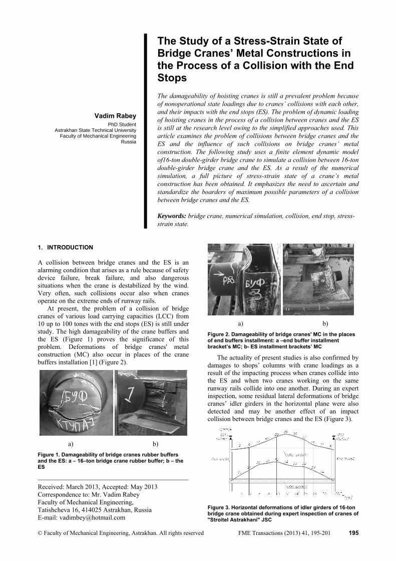
A collision between bridge cranes and the ES is an alarming condition that arises as a rule because of safety device failure, break failure, and also dangerous situations when the crane is destabilized by the wind. Very often, such collisions occur also when cranes operate on the extreme ends of runway rails.
At present, the problem of a collision of bridge cranes of various load carrying capacities (LCC) from 10 up to 100 tones with the end stops (ES) is still under study. The high damageability of the crane buffers and the ES (Figure 1) proves the significance of this problem. Deformations of bridge cranes' metal construction (MC) also occur in places of the crane buffers installation [1] (Figure 2).
a) b)
Figure 1. Damageability of bridge cranes rubber buffers and the ES: a – 16–ton bridge crane rubber buffer; b – the ES
a) b)
Figure 2. Damageability of bridge cranes' MC in the places of end buffers installment: a –end buffer installment bracket’s MC; b- ES installment brackets’ MC
The actuality of present studies is also confirmed by damages to shops’ columns with crane loadings as a result of the impacting process when cranes collide into the ES and when two cranes working on the same runway rails collide into one another. During an expert inspection, some residual lateral deformations of bridge cranes’ idler girders in the horizontal plane were also detected and may be another effect of an impact collision between bridge cranes and the ES (Figure 3).
Figure 3. Horizontal deformations of idler girders of 16-ton bridge crane obtained during expert inspection of cranes of "Stroitel Astrakhani" JSC

196 ▪ VOL. 41, No 3, 2013 FME Transactions
Thus, we may talk about the existence of an unregulated loading of bridge cranes in the process of their collision with the ES, the consequences of which may directly have an effect on the safety of the cranes' operation.
It should be noted that Russian as well as other world standards and methods of calculation of bridge cranes' MC [2], in addition to state standards and safety regulations[3,4,5] do not contain complete recommendations that take into account the loads that are induced on bridge cranes in the process of their collision with the ES. In addition, methods of calculating such loads are inexact. The critical parameters which are omitted from virtually all standards are:
1) a mass of the payload and its vertical and horizontal positions at the moment of impact; 2) dynamic effects such as the swaying of a payload and/or the deformation of the end buffers; 3) elastic deformations of a crane’s MC during impact; 4) a longitudinal misalignment of one of the ES. The influence of an impact loading on bridge cranes
normative service life of which has been exhausted or MC of which has been subjected to repeated repair is also important.
There are a number of scientific studies devoted to the study of a collision between bridge cranes and the ES [6]. However, none of the studies could determine and take into account real behavior of bridge cranes' MC in the process of a collision between the cranes and the ES because mathematical as well as computational models of the cranes were too simplified (Figure 4).
a) b)
c)
Figure 4. Computational models of a bridge crane collision with: a – the collisional ES by P.Z. Petukhov [7]; b – the gravitational (unshocked) ES by A.V. Martynov [8]; c- the collisional ES by T.N. Haas [9]
2. NUMERICAL ANALYSIS (FEA) OF A COLLISION BETWEEN THE 16-TON DOUBLE-GIRDER BRIDGE CRANE AND THE ES
For further study of this problem, the author of this article created a non-linear finite-element computational model (CM) of the 16-ton double-girder bridge crane as a system with many degrees of freedom (DOF) reflecting the real MC of a crane (Figure 5a,b) that is operated at the "Stroitel Astrakhani" JSC enterprise in Astrakhan (Russia).
a)
b)
Figure 5. 16-ton double-girder bridge crane: a- construction model: 1- crane MC; 2 – load trolley; 3-traveling wheels; 4-crane buffers;5- ES; 6-bridge rails; 7-runway rails; 8- payload; b- CM
A CM of the bridge crane (see Figure 5b) consists of 34367 finite elements (FE) and 26903 nodes: 87 beam FE, 11017 shell FE, 21548 solid FE, 1715 rigid and joint constraints (contact elements). The data of the FE model presented in Table 1.
The main objective of this work was the study of collisional process of double-girder bridge crane’s MC with the ES, therefore work of drive motors of the crane, rotation of crane’s wheels were not taken into account. Due to the complexity of bridge crane’s construction some simplifications were done to obtain a computationally efficient FE model, first of all it was exclusion of rotating masses.
Nonlinear interaction properties between travelling wheels and runway rails in CM were modelled with a coefficient of rolling friction (µr) in the longitudinal direction, coefficient of sliding friction (µs) in the lateral
FME Transactions VOL. 41, No 3, 2013 ▪ 197
direction and vertical contact pressure, the calculations and values of which were taken from [10]. The energy losses due to various components in the crane motors can not be neglected, as this increases the coefficients of friction (µr, µs). Thus, the total coefficients of friction were estimated as: µs=0,4, µr=0,001.
Table 1. The data of the FE model
Construction elements of FE model
Type of construction element and dimensions
Material Type and number of
finite elements (FE)
Idler girders Box section 1185x550mm Bridge span 22500 mm
Steel St3ps with a yield limit of 250
MPa (GOST380-
94)
9654 four node quadrilateral
shell FE
End trucks Box section 450x350 mm Length 5000
mm
Steel St3ps 1182 four node quadrilateral
shell FE
Bridge rails Rail profile Length 22500
mm
Steel St65G with a yield limit of 785
MPa
984 eight node hexahedron
and five node wedge solid
FE Runway rails Rail profile
Length Steel St65G 902 eight node
hexahedron and five node wedge solid
FE Bridge crane
travelling wheels
Diameter 710mm
Steel St3ps 840 four node tetrahedron
solid FE Load
trolley’s metal
construction
End trucks, longitudinal
girders, flooring
Steel St3ps 307 four node quadrilateral
shell FE
Load trolley's
travelling wheels
Diameter 320 mm
Steel St3ps 448 four node tetrahedron
solid FE
Load cables Diameter 17,5 mm
Steel with E=1·105
MPa (GOST 3077-
80[11])
97 three-dimensional
two node shear-flexible (Timoshenko)
beam FE Payload Rectangle
shape Steel St3ps 1 hexahedron
solid FE Crane buffers
200x200 mm Rubber 7IRP-18-1348 (TU 2500-376-00152106-
94 [12])
18048 four node
tetrahedron solid FE
End stops H-section 820x1900 mm
Steel St3ps 110 four node quadrilateral
shell FE Dampers 300x200x200
mm Wood 72 hexahedron
solid FE
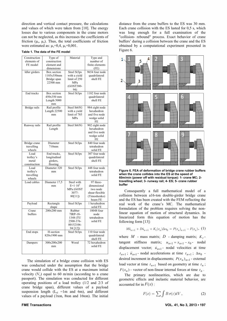
The simulation of a bridge crane collision with ES
was conducted under the assumption that the bridge crane would collide with the ES at a maximum initial velocity (Vc) equal to 60 m/min (according to a crane passport). The simulation was conducted for different operating positions of a load trolley (1/2 and 2/3 of crane bridge span), different values of a payload suspension length (Lsl =1m and 6m), and different values of a payload (1ton, 8ton and 16ton). The initial
distance from the crane buffers to the ES was 30 mm. Each crane collision with the ES lasted for 0,5 s, which was long enough for a full examination of the "collision- rebound" process. Exact behavior of crane buffers’ during a collision between the crane and the ES obtained by a computational experiment presented in Figure 6.
Figure 6. FEA of deformation of bridge crane rubber buffers when the crane collides into the ES at the speed of 60m/min (power off with residual torque): 1- crane MC; 2- travelling wheel; 3- runway rail; 4- ES; 5- crane rubber buffer
Consequently a full mathematical model of a collision between a16-ton double-girder bridge crane and the ES has been created with the FEM reflecting the real work of the crane’s MC. The mathematical formulation of the problem requires solving the non-linear equation of motion of structural dynamics. In linearized form this equation of motion has the following form [13]:
1 1 t 0 1( ) ( ) ( )n n n n n nMu Du K x u P x F x+ + ++ + D = - , (1)
where M - mass matrix; D - damping matrix; tK -
tangent stiffness matrix; 011 xxu nn - nodal
displacement vector; 1nu - nodal velocities at time
1nt ; 1nu - nodal accelerations at time 1nt ; 0u -
desired increment in displacements; 1)( nnxP - external
load vector at time 1nt based on geometry at time nt ;
)( nxF – vector of non-linear internal forces at time nt . The primary nonlinearities, which are due to
geometric effects and inelastic material behavior, are accounted for in )(xF :
T( ) ( )e
e
Ve
F x B dVs e= åò , (2)
198 ▪ VOL. 41, No 3, 2013 FME Transactions
x
xFxK
)(
)(t , (3)
where B – strain-displacement matrix; eV – volume
of the finite element. Eq. (1) is solved by the unconditionally stable, one-
step, Newmark -β time integration scheme:
1 2
1 1
2n
n nuu
u utt
bb bb
+æ öD ÷ç= - - - ÷ç ÷ç ÷è øDD
, (4)
( )1 11n n n nu u t u tug g+ += + D - + D , (5)
1n nx x u+ = + D , (6)
where and - the free parameters of integration;
nn ttt 1 - the time step size;
nu - nodal velocities
at time nt ;
nu - nodal accelerations at time nt ; 1nu -
nodal accelerations at time 1nt ; nn uuu 1 .
For 2/1 and 4/1 the Newmark method becomes the constant average acceleration method. For
2/1
и 22/14/1 numerical damping is induced into the solution leading to a loss of energy and momentum.
In the FE model the damping was specified at the structural level as Rayleigh damping. Viscous damping force is obtained as
ukiF nd , (7)
where - Beta Rayleigh damping constant: for steel
and for rubber material values of 0,001 and 0,05 were taken respectively; k – stiffness of the vibrating system;
n -natural frequency of the system; u -displacement of
the vibrating system.
3. EXPERIMENTAL RESULTS AND DISCUSSION
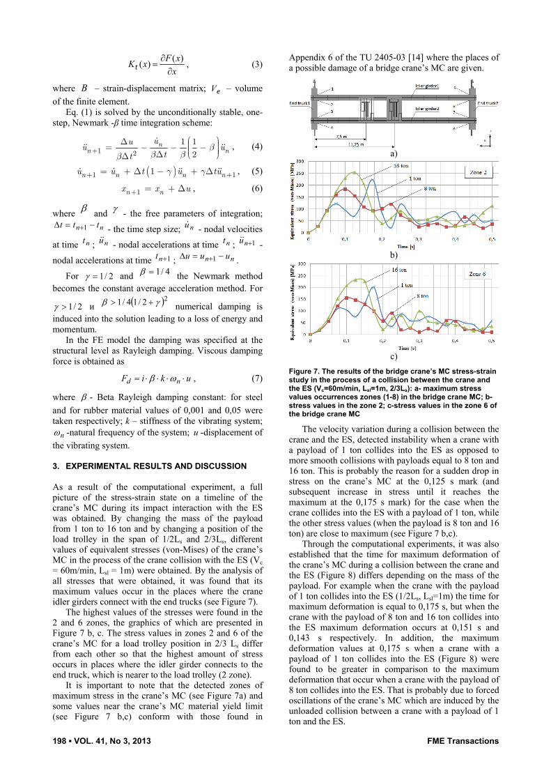
As a result of the computational experiment, a full picture of the stress-strain state on a timeline of the crane’s MC during its impact interaction with the ES was obtained. By changing the mass of the payload from 1 ton to 16 ton and by changing a position of the load trolley in the span of 1/2Ls and 2/3Ls, different values of equivalent stresses (von-Mises) of the crane’s MC in the process of the crane collision with the ES (Vc = 60m/min, Lsl = 1m) were obtained. By the analysis of all stresses that were obtained, it was found that its maximum values occur in the places where the crane idler girders connect with the end trucks (see Figure 7).
The highest values of the stresses were found in the 2 and 6 zones, the graphics of which are presented in Figure 7 b, c. The stress values in zones 2 and 6 of the crane’s MC for a load trolley position in 2/3 Ls differ from each other so that the highest amount of stress occurs in places where the idler girder connects to the end truck, which is nearer to the load trolley (2 zone).
It is important to note that the detected zones of maximum stress in the crane’s MC (see Figure 7a) and some values near the crane’s MC material yield limit (see Figure 7 b,c) conform with those found in
Appendix 6 of the TU 2405-03 [14] where the places of a possible damage of a bridge crane’s MC are given.
a)
b)
c)
Figure 7. The results of the bridge crane’s MC stress-strain study in the process of a collision between the crane and the ES (Vc=60m/min, Lsl=1m, 2/3Ls): a- maximum stress values occurrences zones (1-8) in the bridge crane MC; b- stress values in the zone 2; c-stress values in the zone 6 of the bridge crane MC
The velocity variation during a collision between the crane and the ES, detected instability when a crane with a payload of 1 ton collides into the ES as opposed to more smooth collisions with payloads equal to 8 ton and 16 ton. This is probably the reason for a sudden drop in stress on the crane’s MC at the 0,125 s mark (and subsequent increase in stress until it reaches the maximum at the 0,175 s mark) for the case when the crane collides into the ES with a payload of 1 ton, while the other stress values (when the payload is 8 ton and 16 ton) are close to maximum (see Figure 7 b,c).
Through the computational experiments, it was also established that the time for maximum deformation of the crane’s MC during a collision between the crane and the ES (Figure 8) differs depending on the mass of the payload. For example when the crane with the payload of 1 ton collides into the ES (1/2Ls, Lsl=1m) the time for maximum deformation is equal to 0,175 s, but when the crane with the payload of 8 ton and 16 ton collides into the ES maximum deformation occurs at 0,151 s and 0,143 s respectively. In addition, the maximum deformation values at 0,175 s when a crane with a payload of 1 ton collides into the ES (Figure 8) were found to be greater in comparison to the maximum deformation that occur when a crane with the payload of 8 ton collides into the ES. That is probably due to forced oscillations of the crane’s MC which are induced by the unloaded collision between a crane with a payload of 1 ton and the ES.

FME Transactions VOL. 41, No 3, 2013 ▪ 199
a)
b)
Figure 8. Maximum deformational state of the bridge crane MC when the crane collides into the ES (Vc=60m/min, Lsl=1m) depending on a position of the load trolley: a-1/2Ls; b-2/3L
It was significant to note that the results that were obtained by the computational experiment method on the basis of the finite element analysis (FEA) corroborated the fact that lateral deformations of the crane’s idler girders in the horizontal plane indeed may occur after a collision between the crane and the ES.
The values of the obtained stress which occurs in the elements of the computational model of the crane, show a possibility of residual deformations when the crane collides into the ES with maximum crane load parameters: Vc=60m/min and Lsl=1m. In addition,
equally dangerous situations can appear during collisions between the crane and the ES when the load trolley is positioned in the 1/2Ls as well as in the 2/3Ls. Besides the deformations of crane’s idler girders, cracking is also a possibility in places where the idler girders and the end trucks connect together (Figure 9).
The greatest danger of such impacts with the ES is for bridge cranes' MC, which was subjected to repair, especially around the connections between the idler girders and the end trucks.

200 ▪ VOL. 41, No 3, 2013 FME Transactions
Figure 9. A particular example of a crack in a T-joint connection of an idle girder and an end truck
4. CONCLUSION In conclusion, it should be noted that by means of the CM that is depicted in Figure 5 a realistic pattern of behavior for the 16-ton double-girder bridge crane’s MC was estimated during a collision between the crane and the ES. A finite element model of the bridge crane, on the basis of a real constructional model, made it possible to obtain new research results such as a full picture on a time line of a stress-strain state of the crane’s MC. According to computational experiments, it has become absolutely necessary to take measures to establish a standardized set of maximum-possible parameters of the dynamic process of a collision between bridge cranes and the ES, especially when cranes operate at the extreme ends of runway rails.
It should be noted, that horizontal deformations of idle girders of real bridge crane shown in Figure 3 are accumulated with the years residual deformations due to skew loadings, horizontal forces etc. Through computational experiments it was observed that horizontal deformations of idle girders may also occur due to impact loadings as the result of bridge crane collision with the ES. It is significant to note, that horizontal deformations of idle girders, obtained by FEA (shown in Figure 8), are not residual deformations but rather present themselves as maximum elastic deformations occurring in the process of collision between crane and the ES. Under often occurrence of such deformations with the time being they can transit to residual deformations because of exhausting of resource characteristics (stress cycles) of idle girders’ welded joints as well as bearing capacity of the idle girders themselves. This explains extremely high difference between the values of horizontal deformations obtained by measurement (Figure 3) and by FE analysis (Figure 8).
Damages (cracks) that often occur in way of connection of idle girders with end trucks, such as presented in Figure 9, tells that this place still remains one of the most massive stress concentrator in the metal construction of bridge cranes of all types. Stress state values in places of connection of idle girders with end trucks, occurring due to crane collision with the ES, according to the results of computational experiments, may also be a reason of cracks’ formation.
It was significant to note that the computational experiment results obtained in this article probably have their drawbacks and therefore need more precise definition. The flexibility of the bridge crane support structure, which was not taken into account, is perhaps the first drawback of this study. From [15,16] it is known that the flexibility of the crane support structure has a definite effect on the magnitude of the impact forces and the interaction between the crane buffers and the ES. It therefore must influence the behavior of the crane’s MC. If the crane collides into the ES with the drive motors fully engaged ("power-on" condition) this will also have an effect on the results of a stress-strain state of the crane’s MC. On the results of a computational experiment, a longitudinal misalignment or a total absence of one of the ES will also have significant influence. The problem of a collisional interaction of two bridge cranes working on the same runway rails continues to dominate.
It should be noted also that, in spite of some simplifications by the computational experiment that was described in the present article, new data on the study of a collision between bridge cranes and the ES were obtained, which could not be obtained in the previous scientific studies that were described in [6].
REFERENCES
[1] Rabey,V.: Study of overhead crane’s buffers state, Vestnik of ASTU - Vol. 53, No 1, pp. 49-53, 2012 (in Russian).
[2] STO 24.09-5821-01-93, Russian Standard: Industrial Load-Lifting Cranes, Standards and Methods for Steel Construction Elements Calculations, 1993 (in Russian).
[3] PB 10-382-00, Russian Standard: Rules of Arrangement and Safe Use of Load-Lifting Cranes, 2000 (in Russian).
[4] EN 1991-3:2003, European Standard: EUROCODE 1, Actions On Structures, Part 3: Actions Induced By Cranes and Machinery, 2003.
[5] AS 1418.18:2001, Australian Standard: Cranes (Including Hoists and Winches), Part 18: Crane Runways and Monorails, 2001.
[6] Panasenko, N. and Rabey, V.: The condition of the studies concerning dynamics of collision between load-lifting cranes and the end stops, Innovative Technologies in Machine Construction: Problems, Tasks, Solutions- Vol. 1, No 1, pp. 186-192, 2012 (in Russian).
[7] Petukhov,P.: About calculation of hydraulicbuffers, Questions of Theory and Function of Lifting-and-Transport Machines- Vol. 56, pp. 5-14, 1955 (in Russian).
[8] Martynov,A.: Study of Gravitational Slowdown of Bridge Cranes and Cranes’ Trolleys, Candidate of technical science dissertation, Research-and-Production Enterprise, Novocherkassk, 1976 (in Russian).
[9] Haas,T.: Numerical (FEA) Evaluation of Crane End Buffer Impact Forces, Doctorate degree
FME Transactions VOL. 41, No 3, 2013 ▪ 201
dissertation, University of Stellenbosch, Stellenbosch, 2007.
[10] Aleksandrov, M: Lifting-and-Shifting Machines, M: Vysshaya Shkola, Moscow, 1972 (in Russian).
[11] GOST 3077-80, Russian Standard: Double-Lay Rope of LK-O Type, 1980 (in Russian).
[12] TU 2500-376-00152106-94, Russian Standard: Rubber Technical Production, 1994 (in Russian).
[13] Hallquist, J.O.: LS-DYNA Theoretical Manual, Livermore Software Technology Corporation, California, 2005.
[14] TU 24-05-03, Russian Standard: Regulations of Complete Overhaul, Complete and Corrective Maintenance of Bridge Cranes’ Metal Constructions, 2003 (in Russian).
[15] Haas, T.N., Mainoon, P., Dunaiski, P.E.: Estimation of the maximum end buffer impact force for a given level of reliability, Journal of the South African Institution of Civil Engineering – Vol.54,No 1,pp. 63-68, 2012.
[16] Haas, T.N., Mainoon, P., Dunaiski, P.E.: The effect of parameters on the end buffer impact force history of the crane, Journal of the South African
Institution of Civil Engineering – Vol.54,No 1,pp. 55-62, 2012
ИСТРАЖИВАЊЕ НАПОНСКО-
ДЕФОРМАЦИОНИХ СТАЊА МЕТАЛНЕ КОНСТРУКЦИЈЕ МОСНИХ ДИЗАЛИЦА ПРИЛИКОМ УДАРА О ОДБОЈНИКЕ
Вадим Рабеј
Анализа оштећења дизалица приликом судара је значајан проблем, јер ударна оптерећења која настају при нпр. међусобном судару дизалица или при њиховом удару у крајње одбојнике не спадају у категорију тзв. радних оптерећења. У раду су анализирана динамичка оптерећења при удару дизалице о одбојнике, као и утицај тих оптерећења на металну конструкцију дизалице. Удар дизалице назначене носивости 16 тона о одбојнике је анализиран применом МКЕ. Нумеричком симулацијом је добијено напонско-деформационо стање у носећој структури дизалице.