The Sart canal bridge - Freyssinet€¦ · working on the Sart Canal Bridge. Why was this...
24
reyssinet Belgium The Sart canal bridge MAY / AUGUST 2001 - No. 211
-
Upload
truongminh -
Category
Documents
-
view
215 -
download
0
Transcript of The Sart canal bridge - Freyssinet€¦ · working on the Sart Canal Bridge. Why was this...

reyssinet
Belgium
The Sart canalbridge
MAY / AUGUST 2001 - No. 211
GB 211 couverture et 4e 12/07/01 16:24 Page 3

Co
nte
nts
Contents
2Freyssinet magazine May / August 2001 - No. 211
ARGENTINAFreyssinet-Tierra Armada S.A.
Buenos AiresPhone: (54.11) 43 72 72 91Fax: (54.11) 43 72 51 79
BRAZILSTUP Premoldados Ltda
São PauloPhone: (55.11) 3873 27 34Fax: (55.11) 3672 85 02
Freyssinet LtdaRio de JaneiroPhone: (55.21) 3221 85 00Fax: (55.21) 3852 79 26
Terra Armada S.A.
Rio de JaneiroPhone: (55.21) 233 73 53Fax: (55.21) 263 48 42
CANADAReinforced Earth Company Ltd
OntarioPhone: (1.905) 564 08 96Fax: (1.905) 564 26 09
COLOMBIASTUP de Colombia
BogotaPhone: (57.1) 257 41 03Fax: (57.1) 610 38 98
Tierra Armada
BogotaPhone: (57.1) 236 37 86Fax: (57.1) 610 38 98
EL SALVADORFessic S.A. de C.V.
La LibertadPhone: (503) 2 78 07 55 Fax: (503) 2 78 04 45
GUATEMALAPresforzados Técnicos S.A.
Ciudad Guatemala Phone: (502) 282 96 59Fax: (502) 250 01 50
MEXICOFreyssinet de México
S.A. de C.V.
Mexico D.F.Phone: (52) 5250 70 00Fax: (52) 5255 01 65
Tierra Armada S.A. de C.V.
México D.F.Phone: (52) 5250 17 26Fax: (52) 5254 86 65
UNITED STATESFreyssinet LLC
Chantilly, VA Phone: (1.703) 378 25 00Fax: (1.703) 378 27 00
Menard LLC
Vienna, VA Phone: (1.703) 821 10 54Fax: (1.703) 821 14 79
The Reinforced Earth Company
Vienna, VA Phone: (1.703) 821 11 75Fax: (1.703) 821 18 15
VENEZUELATierra Armada CaCaracasPhone: (58.212) 577 90 38Fax: (58.212) 574 77 50
BELGIUMFreyssinet Belgium V.V.VilvoordePhone: (32.2) 252 07 40Fax: (32.2) 252 24 43
Terre Armée Belgium N.V./S.A.VilvoordePhone: (32.2) 252 43 24Fax: (32.2) 252 24 43
DENMARKA/S SkandinaviskSpaendbetonVaerlosePhone: (45.44) 48 08 25Fax: (45.44) 48 12 45
FINLANDOY Jannibetoni ABVaerlose
FRANCEFreyssinet International & CieVélizyPhone: (33.1) 46 01 84 84Fax: (33.1) 46 01 85 85
Freyssinet FranceVélizyPhone: (33.1) 46 01 84 84Fax: (33.1) 46 01 85 85
PPCSaint-RémyPhone: (33.3) 85 42 15 15Fax: (33.3) 85 42 15 10
Menard SoltraitementNozayPhone: (33.1) 69 01 37 38Fax: (33.1) 69 01 75 05
FYROMFreyssinet BalkansSkopjePhone: (389,2) 118 594Fax: (389,2) 118 594
GERMANYSBT Brückentechnik GmbHPlüderhausenPhone: (49.7181) 99 00 0Fax: (49.7181) 99 00 66
Bewehrte Erde GmbHPlüderhausenPhone: (49.71 81) 99 00 70Fax: (49.71 81) 99 00 75
GREECEFreyssinet Ellas S.A.AthensPhone: (30.1) 69 29 419Fax: (30.1) 69 14 339
FredraAthènesPhone: (30.1) 60 20 500Fax: (30.1) 66 27 748
HUNGARYPannon Freyssinet kftBudapestPhone: (36.1) 466 90 04Fax: (36.1) 209 15 10
IRELANDReinforced Earth Co.
KildarePhone: (353) 4543 10 88Fax: (353) 4543 31 45
ITALYFreyssinet Italia S.r.l.Terra Armata S.p.A.RomaPhone: (39.06) 418 771Fax: (39.06) 418 77201
Freyssinet Italia S.r.l.MilanPhone: (39.02) 895 402 76Fax: (39.02) 895 404 46
NETHERLANDSFreyssinet Nederland B.V.WaddinxveenPhone: (31.18) 26 30 888Fax: (31.18) 26 30 152
Terre Armée B.V.BredaPhone: (31.76) 531 93 32Fax: (31.76) 531 99 43
NORWAYA/S Skandinavisk Spennbeton SnarøyaPhone: (47.67) 53 91 74
POLANDFreyssinet Polska Sp. z o.o.MilanõwekPhone: (48.22) 792 13 86Fax: (48.22) 724 68 93
PORTUGALArmol-Freyssinet LtdaLisbonPhone: (351.21) 716 1675Fax: (351.21) 716 4051
Terra Armada LtdaLisbonPhone: (351.21) 716 1675Fax: (351.21) 716 4051
ROMANIAFreyrom S.A.BucarestPhone: (40.1) 220 35 50Fax: (40.1) 220 45 41
SPAINFreyssinet S.A.MadridPhone: (34.91) 323 95 50Fax: (34.91) 323 95 51
Freyssinet S.A.BarcelonaPhone: (34.93) 226 44 60Fax: (34.93) 226 59 98
Tierra Armada S.A.MadridPhone: (34.91) 323 95 00Fax: (34.91) 323 95 11
SWEDENAB Skandinavisk Spaennbeton MalmöPhone: (46.40) 98 14 00
SWITZERLANDFreyssinet S.A. MoudonPhone: (41.21) 905 48 02Fax: (41.21) 905 11 01
EUROPE
Freyssinet Magazine, 1 bis, rue du Petit-Clamart 78148 Vélizy Cedex - France. Tel.: (33.1) 46 01 84 21. Fax: (33.1) 46 01 86 86.Internet: www.freyssinet.comPublication manager: Isabelle Pessiot. Contributed to this issue: Fabrizio Averardi, Jérôme Barnier, Laure Céleste, PierreCochez, Stéphane Cognon, Michel Cornu, Carlos Correa, Khelil Doghri, Nuria Fernandez, Jean-Philippe Fuzier, Basilio Gaoat,Ivan Higueras, Andrzej Kandybowicz, Roger Lacroix, Frédéric Massé, Sylviane Mullenberg, Erkal Ozsoy, Tomas Palomares,Bertrand Petit, Gérard Postic, Wong Soon Shing, André Stouffs, Tan Teng Wee. Artistic management: Antoine Depoid.Layout: Grafik Tribu. Translation: Netword. Project leader: Stéphane Tourneur. Editorial secretariat: Nathalie Laville.Photos: Aerofoto Intl, Claude Cieutat, Pierre Cochez, stt, Francis Vigouroux, Freyssinet photo library. Cover page: The SartCanal Bridge Photo-engraving: Trameway/Grafik Tribu. Printing: SIO.
TURKEYFreysasIstanbulPhone: (90.216) 349 87 75 Fax: (90.216) 349 63 75
Reinforced Earth Company Ltd AISIstanbulPhone: (90.216) 492 8424Fax: (90.216) 492 3306
UNITED KINGDOM
Freyssinet UKTelfordPhone: (44) 1952 201 901Fax: (44) 1952 201 753
Reinforced Earth Company LtdTelfordPhone: (44) 1952 201 901Fax: (44) 1952 201 753
AFRICAEGYPTFreyssinet EgyptGisaPhone: (20.2) 303 69 65Fax: (20.2) 345 52 37
345 81 65
SOUTH AFRICA
Freyssinet Posten (Pty) LtdOlifantsfonteinPhone: (27.11) 316 21 74Fax: (27.11) 316 29 18
Reinforced Earth Pty LtdJohannesburgPhone: (27.11) 726 6180Fax: (27.11) 726 5908
Although Freyssinet makes every effort to ensure that the information that it provides is as correct as possible, the editors,employees and agents cannot guarantee the results or be responsible for them in any way.
AMERICA
Spain
Bonaire shopping centrep. 13
United Kin
M50 mThe Op. 23
Interview
Qualityperformof matep. 4
France
Deconstruction of a Bailey bridgep. 14
B
Dap
New GB 211 12/07/01 16:17 Page 1

Contents
3Freyssinet magazine Mai / Août 2001 - n° 211
ASIA
HONG KONGFreyssinet Hong Kong LtdKowloon TongPhone: (852) 27 94 03 22
23 39 83 70Fax: (852) 23 38 32 64
Reinforced Earth Pacific LtdKowloonPhone: (852) 27 823 163Fax: (852) 23 325 521
INDIATAI Aimil joint ventureNew DelhiPhone: (91.11) 695 00 01Fax: (91.11) 695 00 11
INDONESIAPT Freyssinet TotalTechnologyJakartaPhone: (62.21) 830 02 19/22Fax: (62.21) 830 98 41
JAPANF.K.K. TokyoPhone: (81.3) 35 71 86 51Fax: (81.3) 35 74 07 10
Terre Armée K.K.TokyoPhone: (81) 427 22 1134Fax: (81) 427 22 1134
KUWAITFreyssinet International et CieSafatPhone: (965) 571 49 74Fax: (965) 573 57 48
MALAYSIAFreyssinet PSC (M) Sdn BhdKuala LumpurPhone: (60.3) 7982 85 99Fax: (60.3) 7981 55 30
Freyssinet AsiaKuala LumpurPhone: (60.3) 282 95 88Fax: (60.3) 282 96 88
Freyssinet APTO (M) Sdn BhdKuala LumpurPhone: (60.3) 282 95 88Fax: (60.3) 282 96 88
Menard Geosystem Sdn BhdKuala LumpurPhone: (60.3) 5632 1581Fax: (60.3) 5632 1582
Reinforced Earth
OCEANIA
AUSTRALIAAustress Freyssinet Pty LtdSydneyPhone: (61.2) 9674 40 44Fax: (61.2) 9674 59 67
Austress Freyssinet (VIC)Pty LtdMelbournPhone: (61.3) 9326 58 85Fax: (61.3) 9326 89 96
Reinforced Earth Pty LtdSydneyPhone: (61.2) 9910 9910Fax: (61.2) 9910 9999
NEW-ZELAND Reinforced Earth LtdDruryPhone: (64) 9 294 92 86 Fax: (64) 9 294 92 87
ManagementKuala LumpurPhone: (60.3) 6274 6162Fax: (60.3) 6274 7212
PHILIPPINES Freyssinet Philippines S.A. Quezon CityPhone: (63.2) 921 3789 Fax: (63.2) 921 1223
SINGAPOREPSC Freyssinet (S) Pte LtdSingaporePhone: (65) 272 96 97Fax: (65) 272 38 80
Reinforced Earth (S.E.A) Pte LtdSingapourPhone: (65) 272 00 35Fax: (65) 276 93 53
SOUTH KOREAFreyssinet Korea Co, LtdSeoulPhone: (82.2) 515 41 82Fax: (82.2) 515 41 85
Sangjee Menard Co LtdSeoulPhone: (82.2) 587 9286Fax: (82.2) 587 9285
TAIWAN Freyssinet Taiwan EngineeringCo, LtdTaipei Phone: (886.2) 274 702 77Fax: (886.2) 276 650 58
THAILANDFreyssinet Thailand LtdBangkokPhone: (662) 266 6088/6090Fax: (662) 266 6091
UNITED ARAB EMIRATESFreyssinet TAI Middle-East LLCAbou DhabiPhone: (971) 2 445 88 18Fax: (971) 2 445 88 16
VIETNAMFreyssinet International et CieHanoiPhone: (84.4) 826 14 16Fax: (84.4) 826 11 18
Freyssinet International et CieHo Chi Minh-CityPhone: (84.8) 829 92 28Fax: (84.8) 822 35 08
Belgium
The Sart Canal Bridge
p. 8
Thailand
Wat Nakorn-In projectp. 23
ingdom
motorway,Oak3
Egypt
The new Alexandria shopping centrep. 20
Australia
Barcoo OutletTunnelp. 17
Reinforced Earth
Better integration into the
environmentp. 18
Australia
The AuroraPlace glass roof
p. 22y and manceterials
Belgium
Dampers for a footbridgep. 16
New GB 211 12/07/01 16:17 Page 2
The use of high performance mate-rials was included in the specifica-tions imposed on contractorsworking on the Sart Canal Bridge. Why was this recommendationmade?
We cannot talk about high performance mate-rials without introducing the concept of qual-ity rather than high performance concretealone. The canal bridge is an innovation in itscategory since it is made of prestressed con-crete, whereas in the past these structureswere made of steel or reinforced concrete.The Ministry of Development wanted a steelstructure, but we were able to convince themabout the advantages of prestressing for thecanal bridge due to our knowledge of thistechnique, its ease of construction and itsadvantages, and particularly the use of asheathed and greased strands providing per-fect protection. Prestressed concrete appearedto be an economic solution considering thespecific nature of the project, the loads andrelatively short spans.More generally, the requirement for qualityhas existed since the dawn of time, but it waslost in Western Europe during the recon-struction after the Second World War. Thecriterion at the time was fast and inexpensiveconstruction. Between 1945 and 1975 we for-got how to “build well”, and were then carriedaway during the Golden Sixties and Seventiesduring which we lost our points of referenceand lived beyond our means without thinkingof future. The problems due to the oil crisis,the emergence of Japan where the qualityconcept was put into practice, and the real-ization that our buildings built twenty or
Interview
4Freyssinet magazine
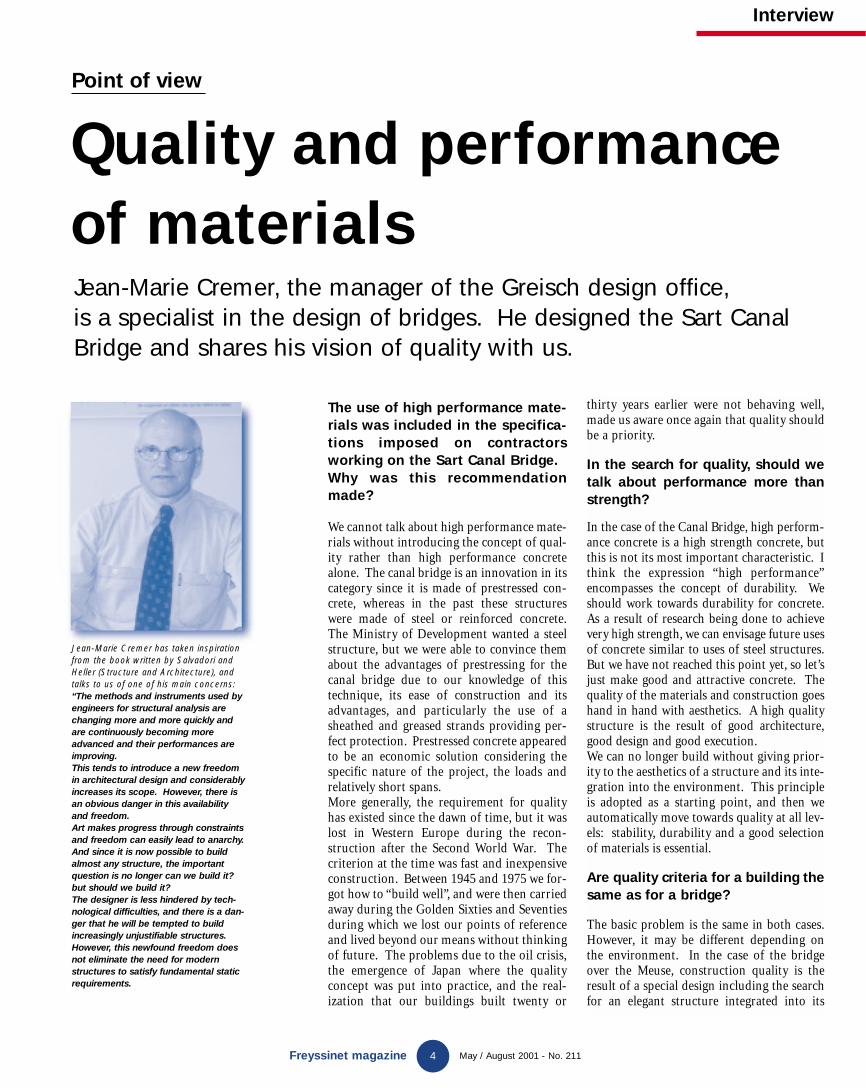
Quality and performanceof materialsJean-Marie Cremer, the manager of the Greisch design office, is a specialist in the design of bridges. He designed the Sart CanalBridge and shares his vision of quality with us.
May / August 2001 - No. 211
thirty years earlier were not behaving well,made us aware once again that quality shouldbe a priority.
In the search for quality, should wetalk about performance more thanstrength?
In the case of the Canal Bridge, high perform-ance concrete is a high strength concrete, butthis is not its most important characteristic. Ithink the expression “high performance”encompasses the concept of durability. Weshould work towards durability for concrete.As a result of research being done to achievevery high strength, we can envisage future usesof concrete similar to uses of steel structures.But we have not reached this point yet, so let’sjust make good and attractive concrete. Thequality of the materials and construction goeshand in hand with aesthetics. A high qualitystructure is the result of good architecture,good design and good execution.We can no longer build without giving prior-ity to the aesthetics of a structure and its inte-gration into the environment. This principleis adopted as a starting point, and then weautomatically move towards quality at all lev-els: stability, durability and a good selectionof materials is essential.
Are quality criteria for a building thesame as for a bridge?
The basic problem is the same in both cases.However, it may be different depending onthe environment. In the case of the bridgeover the Meuse, construction quality is theresult of a special design including the searchfor an elegant structure integrated into its
Point of view
Jean-Marie Cremer has taken inspirationfrom the book written by Salvadori andHeller (Structure and Architecture), andtalks to us of one of his main concerns:“The methods and instruments used byengineers for structural analysis arechanging more and more quickly andare continuously becoming moreadvanced and their performances areimproving.This tends to introduce a new freedomin architectural design and considerablyincreases its scope. However, there isan obvious danger in this availabilityand freedom.Art makes progress through constraintsand freedom can easily lead to anarchy.And since it is now possible to buildalmost any structure, the importantquestion is no longer can we build it?but should we build it?The designer is less hindered by tech-nological difficulties, and there is a dan-ger that he will be tempted to buildincreasingly unjustifiable structures.However, this newfound freedom doesnot eliminate the need for modernstructures to satisfy fundamental staticrequirements.
New GB 211 12/07/01 16:17 Page 3
Interview
5Freyssinet magazine May / August 2001 - No. 211
environment and the use of noble and de luxematerials. It is an urban structure. Howeverthe Canal Bridge is in a less attractive site andhas overwhelming dimensions, consequentlyit is difficult to achieve a successful design andintegration. The structure makes a markacross the landscape. We had a choice betweentwo approaches: either a simple monotonous,understandable and restful structure, or amore animated structure making use of col-ors. We preferred the first option, anddemanded a construction quality that enabledimmediate acceptance of the structure so thatthe structure and its place in the environmentcould be immediately understood. The wallsof the structure are modest with an architec-tonic pattern, the side walls are slightly curvedand the transverse members visible under thedeck make a clear statement about its struc-tural function.Quality also depends on work methods, bothfor the design and construction. Nowadayswe benefit from high performance tools thatwe must use to the best possible extent tooptimize the final performance of the con-struction, taking account of progress made inthe construction of structures and new mate-rials. The best example is prestressing derivedfrom the stay cable technology, using thor-oughly protected greased and sheathed ten-dons that can be replaced, thus offering bettersafety. The choice of incremental launchingfor the canal bridge has enabled us to build astructure with a better than average quality.We chose a method based on its many advan-tages rather than attempting to beat a worldrecord by launching 65 000 tonnes.
What changes are being made in thefields of steel, concrete and newmaterials?
These materials should be considered sepa-rately because of their own different history.For concrete, we are closely monitoring devel-opments in France such as Ultra-HighPerformance Fiber Reinforced Concrete(BFUP). This is a new material that will even-tually need a new approach to design and spe-cial studies. We are moving towards concretethat would have homogenous properties. For“conventional” concrete that we use everyday,we need to work towards increased durabilitywhich is often jeopardized for economic orhuman reasons, since we suffer from a lack ofqualified technical personnel.For steel, significant progress has been madein terms of prestressing with an increase inthe long term resistance. For structural steel,better known, the changes are less spectacular.At Greisch, we are very confident in the use ofcomposite structures for bridges and build-ings, combining the best qualities of concreteand steel. There is no limit to ways of com-bining the two materials. We have about 20 years experience with the behaviour ofcomposite structures, and we are capable ofundertaking daring designs. These solutionscan only be produced by close cooperationbetween concrete specialists and steel special-ists, although these specialists are too fre-quently still in competition with each other.It is also worth mentioning Ultra HighPerformance Synthetic Materials, the adventof which is awaited impatiently. Many prob-
lems remain to be solved in this field and theircost remains very high.
What are the relations between qual-ity requirement and Innovation ?
The quality requirement and strict recom-mendations of the business oblige contractorsto continuously rethink their policies and takerisks. We used new techniques on the Wandrebridge, and we were fortunate in that wefound contractors and suppliers willing totake risks and search for innovative solutions.This was how the waxed unbonded strand wasfirst used, to satisfy a quality requirementabout which everyone is now unanimous.Innovation is the corollary of the qualityrequirement.
Is there a satisfactory and idealquality level?
Quality involves an ongoing search and continu-ous rethinking. Quality is not a matter of stan-dards but rather a matter of organizing andimprovement. Quality must never be stopped,there is a starting point but there should never bean end. The Quality search is unlimited.
The Bridge over Meuse (above) and Wandre (adjacent) Bridge are the result of a town planningstudy to achieve perfect integration into their environment.
New GB 211 12/07/01 16:17 Page 4

France
Mont-Blanc tunnel
France Mexico
Brazil
A new building for the RioStock Exchange
Freyssinet Brazil is participating in the construction of the new head office for the Rio de Janeiro StockExchange subcontracted from Wobrel Construtora SA company,and is supplying and installing post-tensioning cables for the floor slabs on 12 storeys. The slabs are 0.16 m thick and consist of 10 m long 7.5 m wide panels.The total area is 6 000 m2. The floorprestressing uses the Freyssinet C system(4F13) and uses 120 t of steel.
On January 25 this year, Daniel Tardy,president of FNTP (French NationalPublic Works Federation) and MarcelBoiteux, president of the jury of the 10th
Innovation award organized by the FNTP,handed over the second prize to PierreJartoux, Mike McClenahan and IvicaZivanovic from Freyssinet for the “self-protected waterproof bridge suspensionsystem” presented in cooperation withAtofina and Tréfileurope. The individuallyprotected stay cable provided the inspira-tion for COHESTRAND™ which is com-posed of a single 15.7 mm diameter strandprovided with a multi-barrier protectionconsisting of (in order from the insidetowards the outside) galfanization,hydrophobic bonding product covering allwires in the strand bonded to the steel,and a 1.5 mm thick layer of HDPE.COHESTRAND™ is fully compatible withthe Freyssinet anchor system and is appli-cable to large suspension bridges or moremodest structures, new construction andbridge repair. Chartrouse bridge is thefirst application of COHESTRAND™(Freyssinet magazine N°. 207, March 2000).
In brief
Freyssinet magazine 6 May / August 2001 - No. 211
Freyssinet is working on part 5F within a group composed of Bouygues,GTM-Dumez, Impregilo and Freyssinet,for ATMB, the client, and the Scetauroute/ Spea group, the engineer.The work that will employ 50 persons at Freyssinet, is to repair and drain thetunnel roof and the ventilation ducts (100 m2 makeup on the roof and
23 000 m2 waterproofing of the slab),profiling the tunnel roof, coring and drilling of communication openingsbetween ventilation ducts, and finallydrainage and road surfacing work (800 m for the renovation ofactive duct joints). Freyssinet teams will be working six days out of seven, day and night.
Freyssinet de México is participating on behalf of the ICA company on the con-struction of a bridge in the State of Chiapas in the South of Mexico.The bridge passes over an artificial lake and carries the road joining the states of Veracruz and Chiapas. Therefore,the project is very important for Mexico.Its length is 1208 m and its width is 10 mwide, and it comprises eight spans (92 - 152 - 5x168 - 124 m). Initially,the bridge will carry two traffic lanes with
a planned extension to four. The deck is composed of steel box girders with anorthotropic slab, and is built by incrementallaunching. It comprises a 50 m long nose and a cable stayed mast with four pairs of 25T15 cables. The deck is supported by offshore type steel piers formed by four 2.77 diameter main pipes.Freyssinet is responsible for constructionmethods, incremental launching operations,the supply and installation of TETRON®
type bearings and expansion joints.
Freyssinet receivesan award from theFNTP
Chiapas bridge
New GB 211 12/07/01 16:17 Page 5

In brief
7 May / August 2001 - No. 211Freyssinet magazine
As part of the continued expansion andimprovements to the Terminal, a new vehicle and passenger building wasrequired to allow high vehicules accessonto a new range of ferries. Space restrictions limited the ramp to a tightcurvature from dock level, leading to abridge spanning the new customs areaonto the new building roof at ferry accesslevel. The ground conditions across the sitewere poor, with highly compressible alluvial material to considerable depth.Kier Northern were the successful contractor, and a combined solution ofreinforced earth and band drains wasdeveloped between Kiers, Reinforced EarthCompany and Len Threadgold of TheGeotechnical Centre. In addition, a newfacing panel system “TerraQuad” was
developed to achieve the required 18 mradius of the internal ramp walls. Theramp was partially constructed on thecompleted band drains during Autumn2000, with temporary overload placed at the bridge abutment position. Over the winter and Christmas break the rampwas allowed to settle, with the rate anddegree of settlement being monitoredagainst the conjectured figures from calculation. During early 2001 the settlement of approximately 500 mm was sufficiently complete to allow the completion of the last layers of ReinforcedEarth up to finished level, and the construction of the road base and parapets.The bridge abutment was constructed and the bridge beams placed as the mainbuilding construction continued.
TFC®
selectedby the HITEC
The HITEC (High InnovativeTechnologyEvaluation Center)was created withthe objective ofcollecting and disseminatinginformationabout the performance ofnew products.Freyssinet is usingits experiencewith the CarbonFiber Fabrics
(TFC®) process for the strengthening ofstructures, and is actively participating in the program for the evaluation of fiber reinforced polymer composites (FRP) used for the consolidation and repair of concrete,and carried out by the HITEC.This program is supported by the AASHTO(American Association of State Highwayand Transportation Officials) and
the Federal Highway Administration(FHWA). The HITEC works as an independent organization under the control of the CERF (Civil Engineering Research Foundation),within the ASCE. The program is planned to start this year and includes laboratory and in situ tests.
After the Izmir compaction project inTurkey, Carrefour has once again askedMenard Soltraitement to improve soils atthe future Bursa Carrefour shopping centre. The project will include a supermarket, a shopping centre and a twostorey car park with a total floor area of
103 000 m2. The objective on this sitewas to make the large variety of soilmaterials (natural terrain, waste,demolition materials, recent 12 mthick backfill) homogenous and toguarantee an absolute settlement ofless than 15 mm. The stone columnstechnique was used under the foot-ings, and the conventional dynamiccompaction technique was usedunder slabs on grade. Areas withthick overburden were treated usinghigh energy compaction machines.Furthermore, two cranes were rentedlocally for the low energy compactionphases and for the treatment of fairlyshallow areas. The construction
work was completed in three months.Particularly detailed geotechnical monitoring (790 pressure meter tests,five compaction columns and 40 seismictests) were carried out to verify that criteria imposed by the resident engineer(ZETAS) for this work was satisfied.
Turkey
Construction of a supermarket in Bursa
United Kingdom
A new access ramp construction method
United States
San Luis ReyWater TreatmentPlantMenard Soltraitement has recently started upin the United States and is working on the extension to the San Luis Rey WaterTreatment Plant in Oceanside, California.The work is being done using vibro replacement (stone columns).
New GB 211 12/07/01 16:17 Page 6

Belgium
Main characteristics
• Bridge length: 498 m.
• Width between bearings: 33.4 m.
• Width at top: 46 m.
• Weight of bridge: 65 000 t.
• Number of spans: 13.
• Number of columns supporting the deck: 28.
• Water weight: 80 000 t.
• Final weight per column: 6 000 t.
dige
st
New GB 211 12/07/01 16:17 Page 7

Belgium
9Freyssinet magazine May / August 2001 - No. 211
The exceptional di-
mensions of the Sart
Canal Bridge are
necessary for mod-
ernization of the Centre canal.
Freyssinet is supplying and
installing prestressing for the
new bridge.
digest
The Sart CanalBridge
Prestressing
The canal bridge is built using incremental launching of 12 m segments every week.
New GB 211 12/07/01 16:17 Page 8

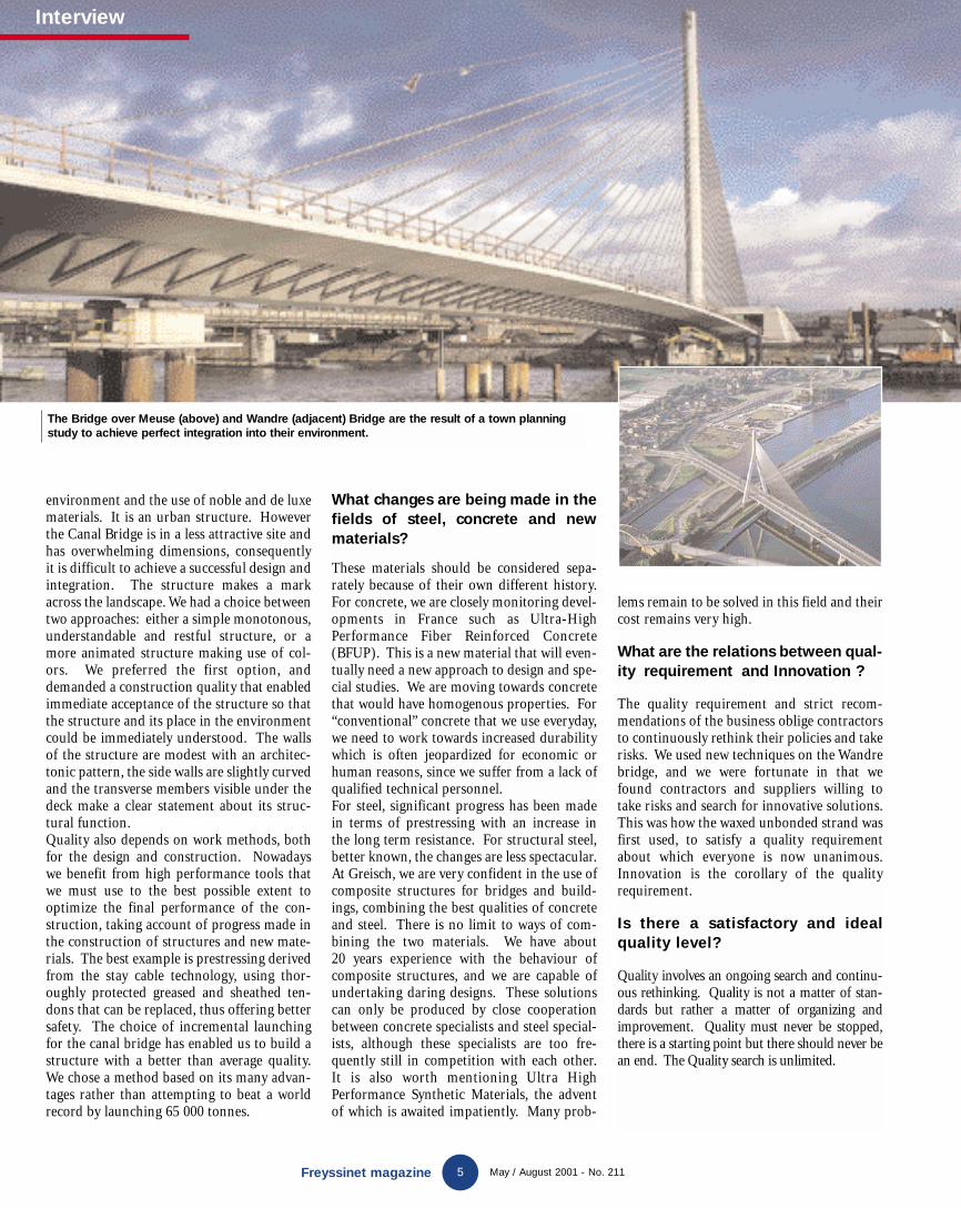
T he Sart Canal Bridge is located close tothe town of La Louvière in Belgium,50 km south of Brussels, and its con-
struction is necessary for modernization ofthe Center canal, now restricted to 300 tonnesconvoys and classifiedas World Heritage byUnesco. It connectsthe Scheldt dock tothe Meuse dock, andwill carry 1 350 tbarges over a valleyeroded by the Thiriauriver and a crossroadsof the RN55 andRN535 roads close toa motorway inter-change.The dimensions of the structure under con-struction are exceptional and it has an inno-vative design that required unusual architec-tural, town planning and landscaping studiesso that it would blend perfectly into its envi-ronment. The 498 m long deck comprisesthirteen 36 m continuous spans and two 15 m cantilever end spans. It is supported on twenty-eight 3 m diameter circularcolumns with 10 m square foundations sup-ported on nine 1.5 m diameter piles 10 to 20 m long. The bottom of the deck is stiff-ened by 111 27 m long fish bellieddiaphragms at c/c distances of 4.5 m. Theaverage thickness of the bottom slab is 40 cmand it is as thick as 60 cm at the piers. Thewidth between bearings is 33.4 m and thewidth at the top is 46 m. The Sart canalviaduct supports 80 000 t of water, eighttimes more than the weight carried by a roadbridge. Pedestrians can walk along the 6 mwide service roads on each side of the canal.The simplicity of forms combined with theuse of high performance materials and dis-
crete facilities contribute towards the genuinecharacter of the Canal Bridge.However, this relaxing architecture conceals aproject with a tricky design and advancedengineering, which mobilized a large number
of engineers, archi-tects and landscapeartists. The structureneeded to be designedto withstand the pres-ence of water at alltimes which is why itis composed of highstrength materials,and the settlement ofthe support pilesneeded to be compati-ble with the magni-
tude of the loads from the structure, witheach column supporting final loads of 6 000 t.
Methods that respect theenvironment
The canal bottom is placed by incrementallaunching of 12 m segments. The prefabrica-tion area is located behind the west abutmentand is like a genuine factory in which manyoperations are automated, resulting in timesavings necessary for execution and the con-struction of 12 m segments every week. Thisorganization guarantees that the structure isuniform and concrete is placed under opti-mum conditions. With this method, it is pos-sible to do the work with no interruption totraffic or effect on the environment.This “plant” comprises storage area for pre-fabricated diaphragms and shuttering slabs,prestressing ducts and a formwork area forintegral prefabrication of reinforcing cages.The deck is equipped with a 21 m nose com-posed of steel webs and prestressed concrete
Freyssinet magazine May / August 2001 - No. 211
Belgium
10
“A longitudinal and transverse
prestressing cable system makes
the bridge perfectlywatertight”
New GB 211 12/07/01 16:17 Page 9
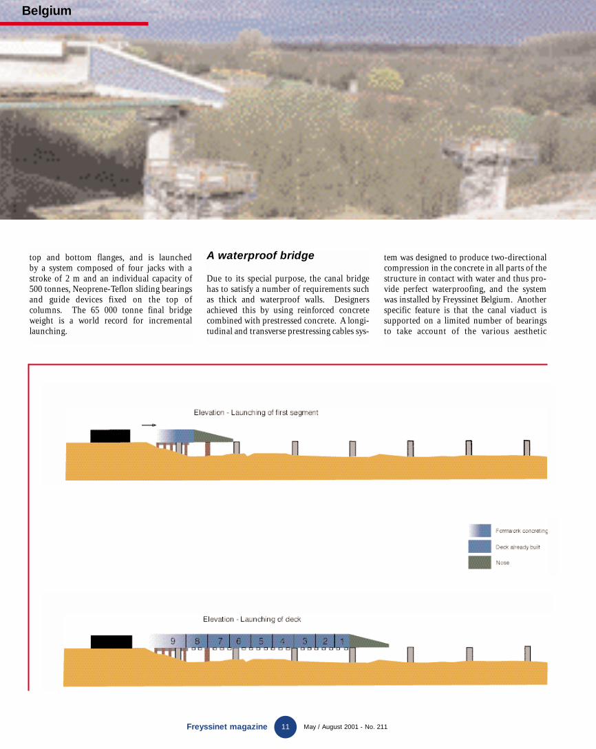
top and bottom flanges, and is launched by a system composed of four jacks with astroke of 2 m and an individual capacity of500 tonnes, Neoprene-Teflon sliding bearingsand guide devices fixed on the top ofcolumns. The 65 000 tonne final bridgeweight is a world record for incrementallaunching.
A waterproof bridge
Due to its special purpose, the canal bridgehas to satisfy a number of requirements suchas thick and waterproof walls. Designersachieved this by using reinforced concretecombined with prestressed concrete. A longi-tudinal and transverse prestressing cables sys-
tem was designed to produce two-directionalcompression in the concrete in all parts of thestructure in contact with water and thus pro-vide perfect waterproofing, and the systemwas installed by Freyssinet Belgium. Anotherspecific feature is that the canal viaduct issupported on a limited number of bearings to take account of the various aesthetic
Belgium
11Freyssinet magazine May / August 2001 - No. 211
New GB 211 12/07/01 16:17 Page 10

12 May / August 2001 - No. 211Freyssinet magazine
and technical criteria. This feature makes the structure very transparent. The continu-ity of the longitudinal load bearing elementcombined with rigid side walls gives goodresistance to earthquake. A number of meas-ures are taken to make the bridge waterproof,such as minimizing the number of expansion joints, the use of dense concrete,the use of three-dimensional prestressing and placement by hot gluing of a water-proofing membrane protected by a coat ofpoured asphalt.The 7.1 m high side walls on each side of thedeck are inclined and protect the externalwalls of the structure against precipitation.The 90 cm thick side walls are longitudinal-ly prestressed in the center by six 27C15 tendons that compensate for the lack of ten-sile strength of the concrete during launchingoperations. Three 27C15 continuity tendons,
tightened after launching and before thecanal viaduct is filled with water, are addi-tional to the device. The diaphragms are prestressed in the factory by two 19C15 ten-dons and two 27C15 tendons installed dur-ing construction of the deck. The longitudi-nal prestressing of the bottom of the canalplaced and tightened during the launchingoperations is composed of fifteen 12C15 tendons. The entire prestressing is appliedusing Freyssinet T15 unbonded strandsthreaded into an HDPE duct grouted with cement grout. This prestressing pro-vides an excellent protection against corro-sion, and can be adjusted and replaced strandby strand.
Participants
Client: SOFICO (Société Wallonne de Financement complémen-taire des Infrastructures - Wallon ComplementaryInfrastructure Financing Company).Engineer: MET D221 (Mons Waterways Division).Design office: Greisch (GEG Group).Inspection office: SECO.Main contractor: BAGECI short termAssociation – CFE – FRANKI CONSTRUCTSpecialized contractor: Freyssinet Belgium.
Belgium
The entire prestressing is applied usingFreyssinet unbonded strands threaded intoan HDPE duct filled with cement grout.
New GB 211 12/07/01 16:17 Page 11

13Freyssinet magazine May / August 2001 - No. 211
Post-tensioned concrete slabs
T he total project occupies an area of400 000 m2, with 250 000 m2 of construc-tion, including the shopping centre itself
that comprises 60 000 m2 of basement carparks, a ground floor occupying 60 000 m2 andis designed to contain shops and recreationareas, also a first floor occupying 40 000 m2
divided into four independent buildings foruse by shopping and leisure areas (cinema,bowling, etc.).The ground floor and the first floor consist ofpost-tensioned concrete slabs 25 to 40 cmthick. The use of prestressing has made it pos-sible to reduce the thickness of the slabs,increase the spans and to obtain 270 x 240floors with no expansion joints on the groundfloor. This solution also made it possible toreduce construction times. The rate of con-struction for a square panel 32 x 32 m was veryquickly reduced to four days including form-work, reinforcement fixing and concreting,and tensioning of the strands. A total area of a100 000 m2 of slabs were constructed and post-tensioned, at an average rate of 3 600 m2 per
week. At this sustained rate, construction ofall slabs was completed in just seven months.This site is a remarkable landmark in the useof post-tensioning in building, since formerlypost-tensioning had only been used in Spainfor bridge construction.
Thinner slabs and even longerspans
The 25 cm thick ground floor slabs are cast insitu and post-tensioned. There are no expan-sion joints. They are constructed in 32 msquare panels. The active reinforcement isbonded and composed of flat ducts containingfour strands each. The conventional reinforce-ment consists of about 1 760 tonnes of steelfor the 60 000 m2 constructed. The 2 757 pre-stressing anchors are of the Freyssinet type4C15. 7184 T15 single strand couplers wereused to achieve continuity of prestressing fromone panel to the next. There is a total of almost322 tonnes of conventional reinforcing steel.
The adopted solution on the first floor on whichfour independent buildings were constructed isidentical to the solution on the ground floor.However, the total area to be constructed issmaller, namely 40 000 m2, whereas the 16 x 16 mspans are larger. 3347 active anchorages, 501passive anchors and 3456 couplers were used forthese floors, with a total of 355 tonnes of activereinforcing and 1760 tonnes of conventionalreinforcing.
Participants
Client: Riofisa SA Group.Engineer: Idom Internacional.Structure engineer and project designer:Engineer Guillermo Corres Peiretti.Main Contractor: Necso Entrecanales y Cubiertas SA.Inspection office: INTEMAC SA.Specialized contractor: Freyssinet SA.
Bonaire shopping centre
The Bonaire shopping centre is a world record for the construction ofbuildings without expansion joints, and is located halfway betweenthe city of Valence and the airport, in the municipality of Aldaia.
Spain
New GB 211 12/07/01 16:17 Page 12

14 Mayo / Agosto de 2001 - n° 211
Bailey bridge
France
Freyssinet magazine
A suspension bridge was built betweenSaint-Gilles and Arles in the Garddepartment, shortly after the Second
World War, to carry national road 572 over thePetit Rhône. This bridge was closed to trafficin 1984 after serious deficiencies wereobserved on the suspension cables, and in1985 it was replaced by a temporary armybridge on the downstream side composed oftwo Bailey bridges. The deck of the bridges iscomposed of 3.05 m long panels forming thetwo main girders. The panels are assembled bypins. The bridge is 3.81 m wide and has woodsurfacing (replaced in 1993), and consists oftwo 39.62 m spans and two 42.67 m spans sup-ported on three piers in the Rhône, giving atotal length of about 165 m. The upstreambridge also includes a pedestrian footbridge.In 1995, an inspection showed that deflectionsin girders were excessive. It was then decidedto reduce the allowable tonnage on the bridgefrom 38 to 19 t and to install heavy strength-ening. A new cable stayed bridge was openedto traffic at the end of 1999, and the temporarybridge considered to be dangerous in rainyweather, noisy due to its wood surfacing andwith insufficient clearance for navigation, waspermanently closed to traffic after fifteen yearsof service. Freyssinet was appointed to disas-semble the bridge, consisting of a total mass tobe moved of about 800 t.
Disassembling the Bailey bridge
All pins and attachments were treated using athread release agent before the work was start-ed. The work started with the disassembly ofthe top bracing and the third level of side lat-tice, consisting of two times three transverse
panels for each bridge. The operation wasdone using a crane located on the existingstructure and the elements were loaded onto aspecial purpose trailer.The second work phase was to restore the lon-gitudinal level of the bridge by lifting the var-ious spans. The existing bearings would thenbe removed. The structure was then placed ontemporary rollers and the four simple spanswere fastened together. This work was donespan by span. Span No. 2 was lifted by 0.35 cmand span No. 1 by 1.5 m on the abutment and0.35 m on pier 1. Span No. 1 was pulledtowards span No. 2 and broached. Permanentrollers were installed on pier No. 1 and on theabutment. The 25 m long rear nose was fixedto the structure on the abutment. It consistedof standard bridge panels. The operation con-tinued by lifting span No. 4 by 3 m on theabutment. A 8 m long preinstalled front nosewas then fixed, which placed the bridge onwood packing on the backfill. This systemavoided the need for 3 m of packing on theabutment. The next step was to lift span No. 3by 1.5 m on pier No. 3 and 0.35 m on pier No. 2, to install temporary rollers. Span No. 3and span No. 2 were broached and placed onfinal rollers located on pier No. 3 and on theabutment.With the bridge thus prepared, the third phase(launching) could be started. Two SC2 jackswere fixed onto a metal frame clamped to theabutment by means of prestressing rods. Thestrand was attached by a metal shoe locatedunder the side beams of the deck. The woodplanks were disassembled as the work progressed to make sure that personnel weresafe at all times until the work on the pierswas complete.
The army Bailey bridge was used for fifteen years as a temporarycrossing over the Petit Rhône and has now been removed.
Deconstruction of a Bailey bridge
New GB 211 12/07/01 16:17 Page 13
Freyssinet magazine Mayo / Agosto de 2001 - n° 21115
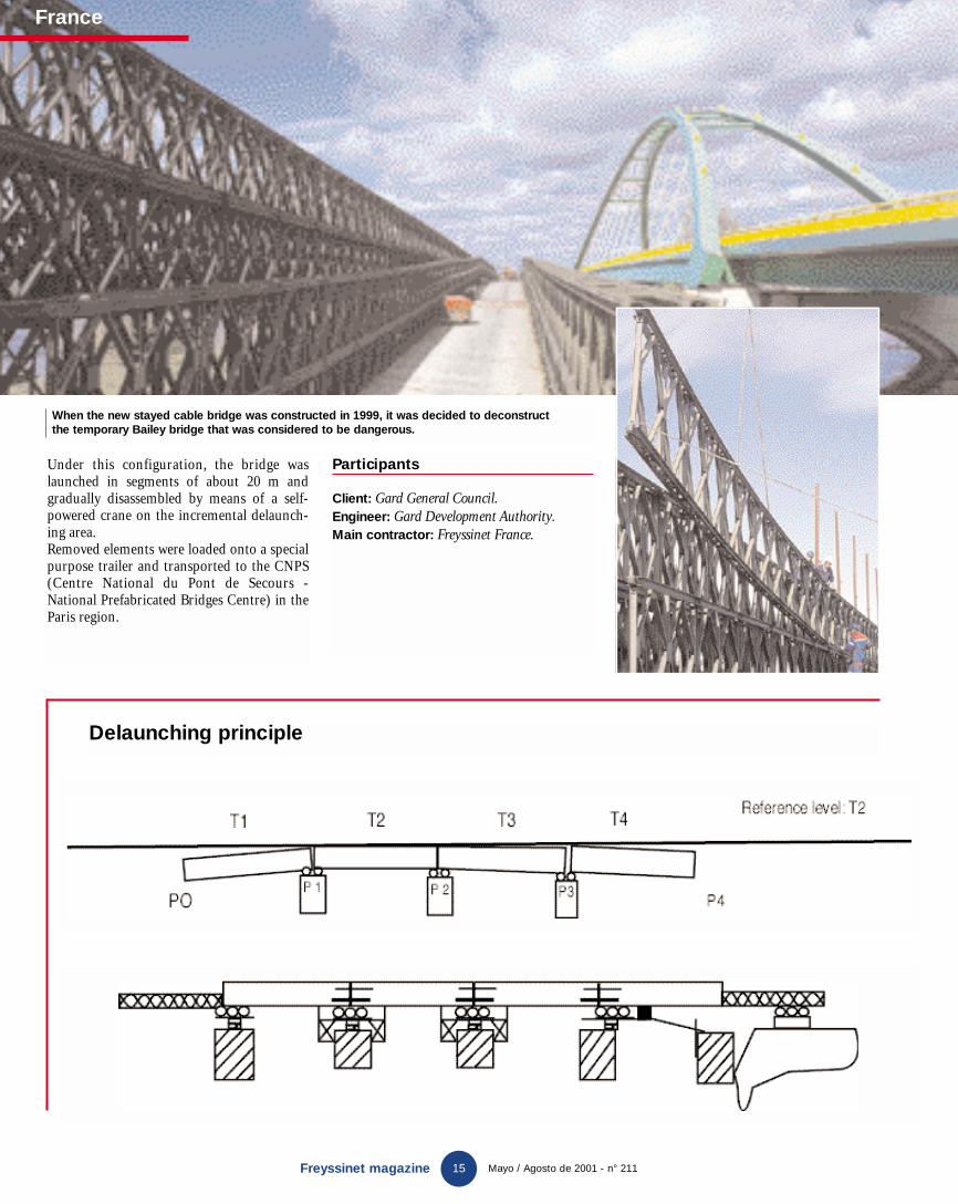
Under this configuration, the bridge waslaunched in segments of about 20 m andgradually disassembled by means of a self-powered crane on the incremental delaunch-ing area.Removed elements were loaded onto a specialpurpose trailer and transported to the CNPS(Centre National du Pont de Secours -National Prefabricated Bridges Centre) in theParis region.
Participants
Client: Gard General Council.Engineer: Gard Development Authority.
Main contractor: Freyssinet France.
When the new stayed cable bridge was constructed in 1999, it was decided to deconstruct the temporary Bailey bridge that was considered to be dangerous.
Delaunching principle
France
New GB 211 12/07/01 16:17 Page 14

A new service station has been built on theE19 motorway between Paris andBrussels close to the town of Nivelles on
the Orival layby, and is protected by an overpass.Samyn was the architect for the overpass-restau-rant currently under construction. The overpassis an innovative structure composed of two mas-ter girders connected by 25 m lattice cross mem-bers supporting the floor of the overpass-restau-rant at the bottom and the roof at the top. Therestaurant, installed at the center of the fourstructure and roof bearings, and supported by 70 m brackets, extends as far as and above bothservice stations.
A vibration problem
The structure is slender. Movements of thebrackets induce significant vertical movementsat the mid-span due to the ratio of the lengthbetween the cantilevers and the central span.These 70 m long very flexible cantilevers canvibrate under the effect of wind and induce ver-tical accelerations at mid-span at the restaurantthat can disturb users.Therefore, the TotalFinaElf company appointedFreyssinet to find a damping solution for thisstructure to lower movements and accelerationsto values that would guarantee the comfort oftheir future customers.
A maximum vertical acceleration of 0.1 m/sec/sec was selected as a comfort criterion.The Technical Department of FreyssinetInternational proposed the use of fourTRANSPEC SHA® hydraulic shock absorbers ateach end of the brackets, to reduce the vibrationphenomenon.
Hydraulic shock absorbers
Based on a model of wind effects carried out bythe SETESCO design office, SigmatecEngineering analyzed the dynamic behaviour ofthe footbridge using a modal analysis of theundamped structure and a time history calcula-tion by direct integration of the response of thedamped structure subject to dynamic pressuresinduced by wind, modeled by harmonic fre-quency functions, the natural frequencies of theundamped structure. The undamped structureis subject to resonant frequencies, the most sig-nificant of which vary firstly between 1.03 and1.04 Hz causing torsion about the longitudinalaxis of the bracket in phase and in phase opposi-tion, and secondly between 1.16 and 1.25 Hzcausing vertical vibration of the brackets inphase and in phase opposition. The sensitivitystudy defined the damping performances andstiffness characteristics required, and was used toselect the shock absorbers. TRANSPEC SHA®
110 – 450 units were used with a nominal capac-ity of 110 kN. The shock absorbers developed by the Technical Department of FreyssinetInternational and made by the PPC companywere installed at the ends of each span. Theyconnect the structure to the ground through acable stayed mast. The length of the TRANSPECSHA® is 1 570 mm including the attachment cle-vis, and the outside diameter is 225 mm. It ishinged at its base to a concrete foundation and isembedded at the top at its connection with thecable stayed mast. The stroke of the TRANSPECSHA® is 450 mm, and they are installed pread-justed such that the distance is 200 mm whenclosed (when the structure moves down) and250 mm when open. This hydraulic shockabsorbing device was determined using a non-linear damping law F = Cvα. The hydraulic reg-ulation device is adjustable and validated by in-situ tests.
Participants
Client: TotalFina Elf.Main contractor: Architect Samyn, SAI Company.Design Office: Setesco.Structural dynamic analysis: Sigmatec.Specialized contractor: Freyssinet Belgium.
Dampers for a footbridge
TRANSPEC SHA®
Freyssinet has been appointed to find a solution for damping vibrations in Orival restaurant above the A19 motorway.
16Freyssinet magazine May / August 2001 - No. 211
Belgium
New GB 211 12/07/01 16:17 Page 15

Freyssinet magazine May / August 2001 - No. 211
Australia
17
T he adopted solution uses TechSpan®arches, due to their engineering advan-tages and the flexibility of construction
using this process. The structure, 4.5 m spanand 5 m high, is composed of precast concreteelements according to the recommendationsmade by the consulting engineer ConnellWagner, forming keyed half shells. The 2.5 mwide arches are manufactured by PCP Pty Ltdin Kilkenny.The TechSpan® process proposed byReinforced Earth Company offers technicaland financial advantages. Technically, thestructure must firstly support the loads andforces from waves, and secondary it mustrespect severe durability requirementsimposed on structures in the saltwater envi-ronment. Thus, 200 m of tunnel is beingplaced inside a coffer dam and will be perma-nently submerged on the sea floor.Engineers at the Reinforced Earth Companychose TechSpan® arches based on the funicu-lar curve theory, and made the best use ofthe properties of concrete by creating a 150 mm thick arch that can bear a 12.5 m of sand and the weight of future 40-tonnetrucks carrying sand in the region. Apartfrom the arches, Reinforced Earth Companyalso participated in the design and supply ofprecast base slabs for the raft, adapted to the geological variations of the seabed,in this case composed mainly of clay
and sand. Each slab was designed takingaccount of the type of seabed.
TechSpan® arches
Barcoo Outlet Tunnel
The Baulderstone Hornibrook company is building a flushing tunnel for the evacuation of water from the Patawallonga lagoon to the ocean in the Glenelg district in Adelaide.
“The structure must withstand loads and forcesdue to waves, while respecting durability requirements imposed on structures in a saltyenvironment.”
New GB 211 12/07/01 16:17 Page 16

Reinforced Earth
18Freyssinet magazine May / August 2001 - No. 211
Better integration into the environment
Architecture
Reinforced Earth is in contact with nature at all times and is continuously developing technologies and products designed for conservation and protection of the environment.
The initial characteristics of ReinforcedEarth products such as their placement(for which no concrete pouring, geogra-
phic modification of sites or heavy machinesare necessary), their faster construction andtheir small influence on the backfill, combinedwith architectonic forms, textures and thevariety of colors of concrete surfaces, enable aharmonious integration of the structures intourban and rural sites. Each project is a specialcase that needs different engineering and plas-tic solutions, as illustrated by the followingfour structures.
Noise absorption wallsfor sound protection
In terms of protection of the environment,Tierra Armada SA has just completed con-struction of a noise absorption screen walldesigned to protect a residential area fromnoise at Barajas Madrid airport (Spain). It is aconventional 2 650 m2 wall with buttresses,9 m high, with a porous concrete soundabsorbing screen on the facing.
double H steel profiles anchored into cast in situ foundations.
Participants
Client: SACYR SA.Main contractor: AENA.Design Office: Setesco.Specialized contractor: Tierra Armada SA.
Reinforced EarthContractor producingworks of artThere has been a growing trend in Texas forowners of proposed retaining walls to specifyunusual facing panels which make an architec-tural statement for their project. No owner hasbeen more active in this regard than the TexasDepartment of Transportation (TxDOT),where Mr. Mark Bloschock, Engineer forSpecial Projects in the Bridge Division, hasprovided both coordination and inspiration.He has served as the coordinator betweenTxDOT’s various geographical Districts andThe noise absorption screen wall is made based
on mortar with wood and cement fibers. Thegrooved finish of the surfaces provides a vari-ety of different decorations and colorings, inharmony with the environment. Its mainadvantages are its high sound insulation,mechanical strength, durability, easy mainte-nance, and that it can be adapted to all types ofground.Due to the unusual height of the noise absorption screens, erection was done using
New GB 211 12/07/01 16:17 Page 17

Reinforced Earth
19Freyssinet magazine May / August 2001 - No. 211
the retaining wall industry, including TheReinforced Earth Company (RECo). Hisefforts have involved various feasibility studies,modelling of structures, and the evaluation ofmethods of construction. His inspirationcomes in the form of encouragement to thevarious Districts that are planning projects.Mr. Bloschock cites that “It is a very competitivething among our District Engineers and thereforeour Districts are trying something different,
pushing the edge, taking a risk, …that sort ofthing.” He added, “The smaller Districts feelthey need to get out there and put themselves onthe map. The artistic thing is something wedeveloped internally. The wagon was developedby them (the Childress District). They initiallyhad a lot of very complex art. We kept the levelof detail down, but kept folks really interested insomething that was unusual.”RECo has been instrumental in this process byoffering specialized designs performed by itsengineering staff in Euless, Texas and by sup-plying high-quality precast panels from itsmanufacturing plant in Waco, Texas. The art-work is typically formed by using full-sizeblockouts made from templates that are pre-pared with precision by RECo’s engineers.These templates are used at RECo’s manufac-turing plant to fabricate the blockouts, whichin turn are carefully set at exact locationswithin the forms. Finally, close control by theproject manager brings the pieces together.The results are remarkable; as Mr. Bloschockstates, “I think everybody who looks at thisdoesn’t really see the joints and doesn’t see anytranslation between the joints – they are seeingthe art. RECo ought to be pretty proud of that
– the wagon and particularly the wheat wall –because you really pulled it off.”The experience of creating wagons, windmills,wheat fields, birds, medallions, viaducts, etc.has given RECo the confidence that it cancontinue to play a major role in meeting thespecial architectural needs of its clients inTexas, and beyond.
A slope stabilized by terraced walls
The embankment needed to be stabilized aspart of the work to widen the RD908 road inthe Hérault department in France; this wasdone by two Reinforced Earth structures tocross over two valleys in the commune ofColombière-le-Poujol. This solution reducedthe surface area occupied by backfill. Thelargest structure with an area of 2 100 m2 anda height of more than 28 m, is the result of anarchitectural study carried out by the archi-tect, André Mascarelli so that it would blendwell into the environment. The adopted solu-tion makes use of TerraClass surfaces laid outin four terraces. The surfacing consists ofwashed gravel from the Vergèze quarry withan architectonic finish composed of horizon-tal grooves on the facing to suggest dry stone.
Full height walls adapted to curvedstructures
600 m of TechSpan tunnel and 10 000 m2
of retaining walls need to be constructed as partof the extension project to the Kwinana Freewayin Western Australia. In July 2000, the West RailCompany appointed Thiess Contractors to perform work on extension of the railway that passes under the new expressway. TheReinforced Earth and TechSpan processes werethen chosen for large sections of railway cut and cover tunnels. The project includes up to 600 meters of TechSpan that is now beingconstructed.The Western Australian Main RoadsDepartment wanted the bridges to be providedwith abutments made from full height panelwalls. Therefore, Reinforced Earth Companydeveloped a unique integrated retaining walland bridge supporting column system for thirteen bridges that formed this part ofthe contract.To erect these massive 8.5 m high panels thecontractor was first required to prepare propsand propping blocks to hold the panels in placefrom the front whilst backfilling took place.Once the panels are in position a full height pre-cast concrete bracket is fitted to the back of thepanel. This bracket, held in place by an anchorpin, creates the void in which the concrete col-umn is poured after backfilling.A further advantage and a unique feature of thefull height panel option is the curvature of thewingwalls. The panels themselves are formed toincorporate a radius 20m curve to the face thatcertainly adds to the aesthetics of the completedstructure.Full height panels are likely to prove to be a pop-ular alternative for designers and contractors inthe future. Their ease of installation and aes-thetics of fewer joints have already won theirsecond project with Barclay Mowlem BGC JointVenture placing an order for a further fourbridges at Northam Bypass in Perth.
An ogival arch was poured in situ near thebottom of the reinforced earth wall, to form apassage to be followed by the stream at thebottom of the valley.
Participants
Client: Hérault General CouncilEngineer: Hérault Development Authority.Architect: André Mascarelli.Main contractor: BEC.Specialized contractor: Terre Armée.
New GB 211 12/07/01 16:17 Page 18

Egypt
20Freyssinet magazine May / August 2001 - No. 211
The new Alexandria shopping centre
Soil consolidation
Menard Soltraitement was appointed to perform soil improvementwork and earthworks on Lake Mariout, where a shopping centre willbe built.
T he greater Alexandria area alreadyextends for more than 20 kilometersalong a narrow coastal strip along the
Mediterranean, and its population is increas-ing sharply in the same way as everywhere elsein Egypt. The only way to build any morelarge infrastructures is to spread inlandtowards the 60-kilometer long Lake Mariout.
Land reclaimed on this semi-marshy salt waterlake has been affected by large settlements, asdemonstrated by the many buildings in whichthe first floor balconies are now at road level.During the year 2000, Menard Soltraitementsuccessfully bid for a contract for the designand execution of soil improvement work andearthworks in order to build a 220 000 m2
shopping centre on reclaimed land on LakeMariout, close to the international airport andthe motorway between Alexandria and Cairo.This shopping centre will eventually be oper-ated by the Carrefour company which hasdecided to make major investments to expandin Egypt.
Pre-consolidation
The nature of the ground, composed of 7 to 8 mthick layers of soft clay and silt and then loosesand, makes special treatment essential toguarantee the durability of the construction.The technical solution presented by MenardSoltraitement as a variant to the basic solutionconsisting of a floor supported on piles, whichis very expensive for an area this large, is basedon preconsolidation of the clay layer using vertical drains together with preloading, andthe use of driven stone filled pillars. The solu-tion proposed by Menard Soltraitement is nowwell advanced for the definition of the shop-ping centre project, and takes account of thedesire expressed by the customer to be able tomove the location of the buildings anywherewithin the covered area, for architectural reasons. Therefore, the grid used for drains,pillars and preloading heights were calculatedby Sigmatec Engineering (Menard Soltraite-ment’s digital calculation and simulation sub-sidiary) to achieve a differential and long termsettlement for a uniformly distributed load of2T/m2 and point loads of up to 70T atunknown locations. The grid of drains and
New GB 211 12/07/01 16:17 Page 19

Egypt
21Freyssinet magazine May / August 2001 - No. 211
preload heights were adapted to the durationsdetermined in planning.
Heavy construction means
The soil improvement and backfill on an area of 220 000 m2 necessitated the placement of1 250 000 m3 of materials, the installation of1 500 000 m of vertical drains (more than sixtimes the distance from Alexandria to Cairo)and the construction of 6 500 driven stonefilled pillars. The work was split into fourphases for which deliveries are staggered fromSeptember 2001 to July 2002. The first seg-ment of the work currently in progress con-sists of 72 000 m2 and 45% of the work, but itmust be completed in only 30% of the totaltime assigned to the soil improvement andearthworks. This is the area in which the firstbuildings in the shopping centre will be builtin September 2001, while soil improvementand earthworks continue on areas set aside forthe future extension of buildings and carparks. It is planned that the shopping centrewill be opened in September 2002.The work actually started in the month ofSeptember 2000 with the construction of a1070 m dike around the site and across lakeMariout, followed by pumping of 300 000 m3
of trapped water. Specialized equipmentbelonging to Menard Soltraitement wasshipped from Europe during this period.Backfill in the first area with a draining workplatform composed of sand was terminated inJanuary 2001, following this the installation ofvertical drains (1500 units per day), the con-struction of driven stone filled pillars (40 unitsper day) and work on applying the preload wascommenced. At the present time, this preloadis being applied at a rate of 10 000 m3 per dayand the same cycle will continue in the secondphase of the works. More than a hundred persons are working on this project. The geot-echnical monitoring of the site is done using120 measurement instruments installed atdepths of up to 15 m.
Participants
Client: MAF MISR.Main contractor: CIA International (Orléans).Specialized contractor: Freyssinet Egypt under license from Menard Soltraitement (Soil improvement and earthworks).
ALEXANDRIA SHOPPING CENTREPROJECT SUMMARY
Building areas Car park areas
Load conditions 70T footings, Uniformly distributed load 2T/m2
Uniformly distributed load 2T/m2
Grid of vertical From 1.10 m to 1.25 m From 1.25 m to 1.50 mdrains
Grid of driven 5.5 m 7 mStone filled columns
Preconsolidation 5 to 7 months 7 to 9 monthstime
Height of preloads 5.7 m to 6.2 m 5.2 m
New GB 211 12/07/01 16:17 Page 20
May / August 2001 - No. 211
Australia
22
The AuroraPlace glass roof
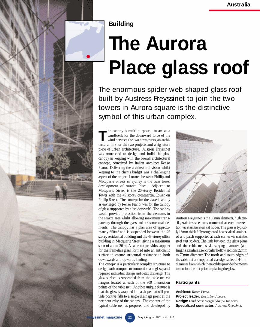
The enormous spider web shaped glass roofbuilt by Austress Freyssinet to join the twotowers in Aurora square is the distinctive symbol of this urban complex.
T he canopy is multi-purpose - to act as awindbreak for the downward force of thewind between the two new towers, an archi-
tectural link for the two projects and a signaturepiece of urban architecture. Austress Freyssinetwas contracted to design and build the glasscanopy in keeping with the overall architecturalconcept, conceived by Italian architect RenzoPiano. Delivering the architectural vision whilstkeeping to the clients budget was a challengingaspect of the project. Located between Phillip andMacquarie Streets in Sydney is the twin towerdevelopment of Aurora Place. Adjacent toMacquarie Street is the 20-storey ResidentialTower with the 45 storey commercial Tower onPhillip Street. The concept for the glazed canopyas envisaged by Renzo Piano, was for the canopyof glass supported by a “spiders web”. The canopywould provide protection from the elements inthe Piazza area whilst allowing maximum trans-parency through the glass and it’s structural ele-ments. The canopy has a plan area of approxi-mately 650m2 and is suspended between the 25storey residential building and the 45-storey officebuilding in Macquarie Street, giving a maximumspan of about 30 m. A cable net provides supportfor the frameless glass, formed into an anticlasticsurface to ensure structural resistance to bothdownwards and upwards loading.The canopy is a particulary complex structure todesign, each component connection and glass panelrequired individual design and detail drawings. Theglass surface is suspended from the cable net viahangers located at each of the 300 intersectionpoints of the cable net. Another unique feature isthat the glass is wrapped into a shape that will pro-vide positive falls to a single drainage point at thenorthern edge of the canopy. The concept of thetypical cable net, as proposed and developed by
Austress Freyssinet is the 18mm diameter, high ten-sile, stainless steel rods connected at each intersec-tion via stainless steel cat nodes. The glass is typical-ly 16mm thick fully toughened heat soaked laminat-ed and patch supported at each corner via stainlesssteel cast spiders. The link between the glass planeand the cable net is via varying diameter (andlength) stainless steel circular hollow sections 22mmto 70mm diameter. The north and south edges ofthe cable net are supported via edge cables of 44mmdiameter from which these cables provide the meansto tension the net prior to placing the glass.
Participants
Architect: Renzo Piano.Project leader: Bovis Lend Lease.Design: Lend Lease Design Group/Ove Arup.Specialized contractor: Austress Freyssinet.
Building
Freyssinet magazine
New GB 211 12/07/01 16:17 Page 21

Freyssinet Thailand Ltd has been working on phase EW-1 of Wat Nakorn-In bridge between Bangkok and Thonburi, since the beginning of the year 2000.
Bringing a motorway bridge up to standards.
Freyssinet magazine May / August 2001 - No. 211
Thailand
23
United Kingdom
T he Sumitomo Construction and Italian ThaiDevelopment joint-venture is the main con-tractor for this project. It comprises firstly the
construction of a cast-in-situ balanced cantileverbox girder bridge over the Chao Praya river (builtusing a travelling formwork) and the accessviaducts on the Thonburi side using the span byspan cast-in-situ box girder method. It alsoincludes the construction of the access viaducts onthe Bangkok side erected with an overhead truss
using the span by span method for the segmentalbox girder and three main bridges crossing over theBangkruai Sanoi road on Thonburi side, and thePitboonsongkram road and the Pracharat road onthe Bangkok side, constructed by the precast seg-mental method. The work done by FreyssinetThailand applies to technical assistance for con-struction methods and prestressing work, the sup-ply and installation of more than 700 tonnes of ten-dons and 1 356 Freyssinet 19C15 type C anchor-
T he Oaks Bridge overpass carries the C2104road between Strensham and Twyning overthe M50 motorway between junction 8 on
the M5 and junction 1 on the M50 in theWorcestershire. Freyssinet UK was appointed tocarry out the complete refurbishment of thebridge deck (including concrete repair, re-water-proofing, replacement joints, new kerbing, re-surfacing, and new safety fencing on theapproaches), the work to break out the existingconcrete handrail and recast to a new profile,
replacement of the steel parapets with alumini-um parapet. The four wing walls were recast andtied together below carriageway with highstrenght bars.Freyssinet chose a cantilevered gantry system asa working platform to carry out hydrodemoli-tion of the existing concrete handrails and also asa falsework support to formwork for the replace-ment concrete. The gantry system was partiallyprefabricated off-site, then erected (and disman-tled) during overnight closures of the M50. The
gantry was fully enclosed, allowing 24 hourworking to proceed for both hydrodemolitionand replacement works over the live motorwaywithout the need for lane closures. In all 40 m3 ofconcrete was removed by hydrodemolition.
Participants
Client: Highways Agency.Engineer: W.S.P. Group Plc.Main contractor: Freyssinet Ltd.
ages in 78 of the box girder viaducts. Each spancomprises six 40 m long 19C15 cables and two 80 m long continuous 19C15 cables. Freyssinet isalso responsible for the conceptual and detaileddesign of the existing overhead erection gantry toadapt it to the project, including the production ofthe construction sequences. The project started inApril 2000 and will be completed in July 2001. Itwill be opened to traffic in the Bangkok Northregion at the beginning of the year 2002.
Wat Nakorn-In project
M50 Motorway, The Oaks
Crossing over the Chao Praya
Repairs
New GB 211 12/07/01 16:17 Page 22

reyssinet
The glass roof between the Philip Street and Macquarie Streettwin towers was designed by the architect Renzo Piano and built by Freyssinet.
Photograph : Adrian Hall
GB 211 couverture et 4e 12/07/01 16:24 Page 2