the research arm of Indiana Center for Network ...rich/OIN.10.2013/OpenFlow Overview.pdf ·...
25
Openflow in two hours Indiana Center for Network Translational Research and Education the research arm of
-
Upload
truonghanh -
Category
Documents
-
view
216 -
download
1
Transcript of the research arm of Indiana Center for Network ...rich/OIN.10.2013/OpenFlow Overview.pdf ·...

Openflow in two hours
Indiana Center for Network Translational Research and Education
the research arm of

Agenda
Overview of OpenFlow
Configure HP switches for OpenFlow
Use Open DayLight to control switches
Watch with WireShark
Play with alternate switch topologies

OpenFlow Controller
FeaturesValue Add
OpenFlow ProtocolEach switch
connects directly with OF Controller

Flow Table
Header Fields Counters Actions
Ingress PortEthernet Source Addr
Ethernet Dest AddrEthernet Type
VLAN idVLAN Priority
IP Source AddrIP Dest AddrIP Protocol
IP ToSICMP typeICMP code
Per Flow CountersReceived PacketsReceived Bytes
Duration secondsDuration nanosecconds
Forward(All, Controller, Local, Table, IN_port, Port#
Normal, Flood)
EnqueueDrop
Modify-Field
Priority

Flow Table
Header Fields Counters Actions
If ingress port == 2 Drop packet
if IP_addr == 129.79.1.1 re-write to 10.0.1.1, forward port 3
if Eth Addr == 00:45:23 add VLAN id 110, forward port 2
if ingress port == 4 forward port 5, 6
if Eth Type == ARP forward CONTROLLER
If ingress port == 2 && Eth Type == ARP forward NORMAL
Priority
32768
32768
32768
32768
32768
40000

Special Ports
Controller (sends packet to the controller)
Normal (sends packet to non-openflow function of switch)
Local (can be used for in-band controller connection)
Flood (flood the packet using normal pipeline)
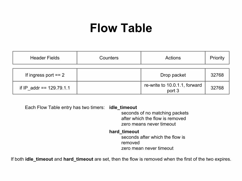
Flow Table
Header Fields Counters Actions
If ingress port == 2 Drop packet
if IP_addr == 129.79.1.1 re-write to 10.0.1.1, forward port 3
Priority
32768
32768
Each Flow Table entry has two timers: idle_timeoutseconds of no matching packetsafter which the flow is removedzero means never timeout
hard_timeoutseconds after which the flow isremovedzero mean never timeout
If both idle_timeout and hard_timeout are set, then the flow is removed when the first of the two expires.

Populating the Flow Table
ProactiveRules are relatively static, controller places rules in switch before they are required.
ReactiveRules are dynamic. Packets which have no match are sent to the controller (packet in). Controller creates appropriate rule and sends packet back to switch (packet out) for processing.

Controller and Switch Communication
● Mode - Controller vs. Listener○ TCP Communication, who initiates conversation
● Mode and Populating Flow Table independent

Example application:topology discovery
OpenFlow Controller

Bootstrapping a new switch
Switch requires minimal initial configuration (e.g., IP address, default GW, and OpenFlow controller)
Switch connects to controller. Controller requests things like a list of ports, etc.
Controller proceeds to determine the switch's location.
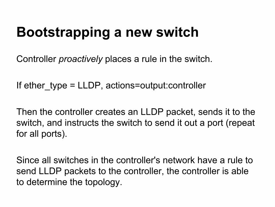
Bootstrapping a new switch
Controller proactively places a rule in the switch.
If ether_type = LLDP, actions=output:controller
Then the controller creates an LLDP packet, sends it to the switch, and instructs the switch to send it out a port (repeat for all ports).
Since all switches in the controller's network have a rule to send LLDP packets to the controller, the controller is able to determine the topology.

Preparing for the hands-on stuffConnect to the wireless OpenFlow SSID
Point your web browser to: http://172.16.1.95/smokeping/Select “Targets” then “Pitcher”
Launch Open DayLight (run.bat or run.sh)
Launch Wireshark and configure it to monitor “openflow” traffic (may have to set decode as under “Analyze menu”
Point a second browser windows to 127.0.0.1:8080username adminpassword admin

Of Note!
Five of you will be configuring the same switch at the same time, so careful.
The vLANs are already defined. Use “write t” to get a feel for the configuration.
vLAN 1 is reserved for telnet access and switch-to-controller connections.

What the network looks like
Smoke PingServer
Smoke PingTarget
Your vLAN
While the vLAN remains configured for native Ethernet switching, smoke ping should indicate positive connectivity!
Port21
Port22

Today’s exercise
Enable OpenFlow on your vLAN, and point it to the controller running on your laptop.
1. Create a controller ID that points to your laptop2. Create an OpenFlow instance for your vLAN3. Make your vLAN a member of your OpenFlow instance4. Point your OpenFlow instance to your controller ID5. Enable OpenFlow for your OpenFlow instance

Create a controller ID that points to your laptop
Of Note: the switches have an OpenFlow context pre-configured
switch1# configswitch1(config)# openflowswitch1(openflow)# controller-id [your vLAN] ip [your laptop IP] controller-interface vlan [your vLAN]
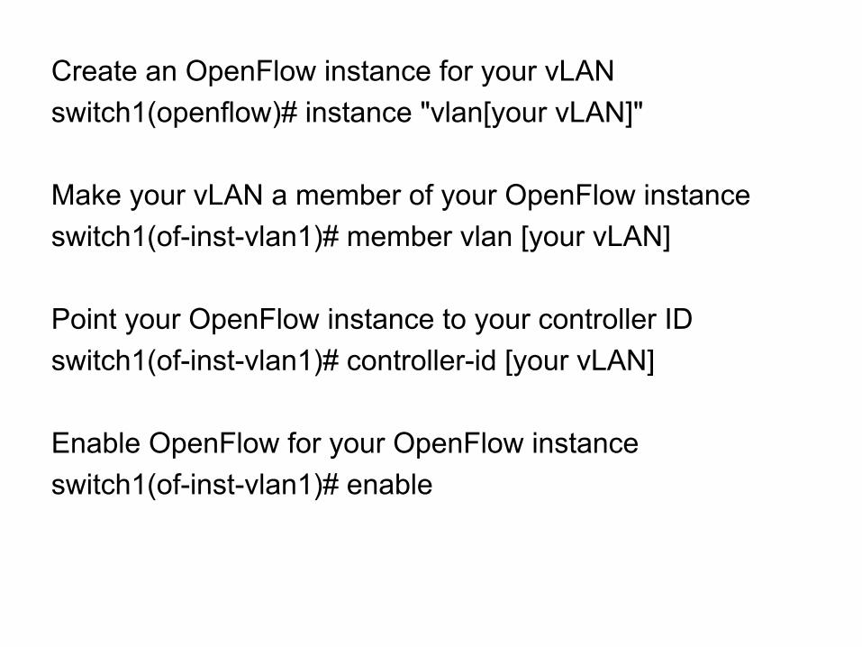
Create an OpenFlow instance for your vLANswitch1(openflow)# instance "vlan[your vLAN]"
Make your vLAN a member of your OpenFlow instanceswitch1(of-inst-vlan1)# member vlan [your vLAN]
Point your OpenFlow instance to your controller IDswitch1(of-inst-vlan1)# controller-id [your vLAN]
Enable OpenFlow for your OpenFlow instanceswitch1(of-inst-vlan1)# enable

switch1# show openflow instance vlan2
Instance Name : vlan2
Admin. Status : Enabled
Member List : VLAN 2
Listen Port : 6634
Oper. Status : Up
Datapath ID : 00020016b96c7280
Mode : Active
Flow Location : Hardware and Software
No. of Hw Flows : 1
No. of Sw Flows : 0
Hw. Rate Limit : 0 kbps
Sw. Rate Limit : 100 pps
Conn. Interrupt Mode : Fail-Secure
Maximum Backoff Interval : 60 seconds
Probe Interval : 10 seconds
Controller Id Connection Status Connection State
------------- ----------------- ----------------
1 Connected Active

Quick, look at smoke ping and ODL!
Why did smoke ping stop working on your vLAN?
Let’s go about fixing that using Open DayLight


fun with more than one switch (bonus section)...
select someone from your switch (you’ll be looking over their shoulder, so pick wisely)
remove vLANs from all other openflow instances, and add them to the one instance (the one belonging to the person you picked)
now there should be five switches showing up on Open DayLight. Bonus, interconnect some of the ports with a patch cable.

Review
HP switch “Virtualization” or hybrid mode.● vLANs are invisible● lots of interesting knobs (implementation
maturing● Controller communications via a
management vLAN
ODL “flows” tab on represents flow installed by ODL