The range of rail-mounted terminal blocks for a perfect ... · The range of rail-mounted terminal...
52
The range of rail-mounted terminal blocks for a perfect electrical installation.
Transcript of The range of rail-mounted terminal blocks for a perfect ... · The range of rail-mounted terminal...

The range of rail-mounted terminal blocksfor a perfect electrical installation.

The new standard for rail-mounted terminal blocks 4
Wire connection 5
Commoning 6
Commoning with staggered jumpers 7
Commoning with step-down jumpers 7
Modular connectors / Testing 8
Marking 9
Product overview 10 – 15
The range of rail-mounted terminal blocksfor a perfect electrical installation.

N-disconnect terminal blocks2.5 (4) mm2 / 6 (10) mm2 / 16 (25 “f-st“) mm2 30
Disconnect terminal blocks for test and measurement 2.5 (4) mm2 / AWG 12 31 – 32
Double deck disconnect terminal blocks for test and measurement 2.5 (4) mm2 / AWG 12 33
Double deck diode and LED terminal blocks2.5 (4) mm2 / AWG 12 34 – 35
Triple deck diode and LED terminal blocks2.5 (4) mm2 / AWG 12 36 – 37
Marking of terminal blocks 38 – 40
Mounting accessories and stickers for operating instructions 41
Ferrules and crimping tools 42 – 43
Examples of circuit configuration 44 – 45
Examples of installation in standard distribution boxes 46 – 47
Examples of circuit configuration with staggered jumpers 48
List of approvals 49
Index of item nos. 50 – 51
Rail-mounted terminal blocks 1.5 (2.5) mm2 / AWG 14 16
Rail-mounted terminal blocks 2.5 (4) mm2 / AWG 12 17
Rail-mounted terminal blocks 4 (6) mm2 / AWG 10 18
Rail-mounted terminal blocks 6 (10) mm2 / AWG 8 19
Rail-mounted terminal blocks 10 (16) mm2 / AWG 6 20
Rail-mounted terminal blocks 16 (25 "f-st") mm2 / AWG 4 21
35° Rail-mounted terminal blocks 1.5 (2.5) mm2 / AWG 14 22
Test plug adapter and testing tap 23
Push-in type wire jumpers 23
Modular connectors 24 – 25
Double deck terminal blocks 2.5 (4) mm2 / AWG 12 26
Triple deck terminal blocks 2.5 (4) mm2 / AWG 12 27
Multilevel installation terminal blocks 2.5 (4) mm2 / AWG 12 28
Multilevel installation terminal blocks 6 (10) mm2 / AWG 8 29

4
up to
smaller
TOPJOB®S DIN 35 rail-mounted terminal blocks with CAGE CLAMP®S technology are thesmallest on the market resulting in a space saving of up to 30%.
The reduction of panel space, smaller enclosures and junction boxes are just some of thecost savings that can be realized.
The new standard for rail-mounted terminal blocks
Simply smaller

5
15°
solid wires
ferruled wires
strandedwires
Wire connection using a screwdriverConnecting stranded conductors without ferrulesor small cross-sectional conductors that cannot bepushed in, is done similar to the original CAGECLAMP®, using a screwdriver.
The smart featureTo open the clamp, the screwdriver is inserted fromthe vertical and the conductor entry is less than 15degrees resulting in easier wiring.
for solid conductors or fine-stranded conductors with ferrules
Stripped solid conductors, stranded conductors with ferrules, or ultrasonically “bonded” conductors are easily connected by simply pushing the wire into thewire entry.
For conductors rated 0.5 mm2 (AWG 20) to 16 mm2
(AWG 6) – this is a significant time and costsaving!
Wire connection – Push-in connectionSolid wires ranging from at least two sizes below toone size above the rated cross section can be pushed indirectly without tools.
Stranded conductors with ferrules ranging from atleast two sizes below the rated cross section up to therated cross section can also be easily inserted withoutusing any tools.
Wire removal The conductor is removed using a screw-driver, like the original CAGE CLAMP®.
Simply push-in
6
500VU2 300V
321
800VU2 600V4 550V
800V
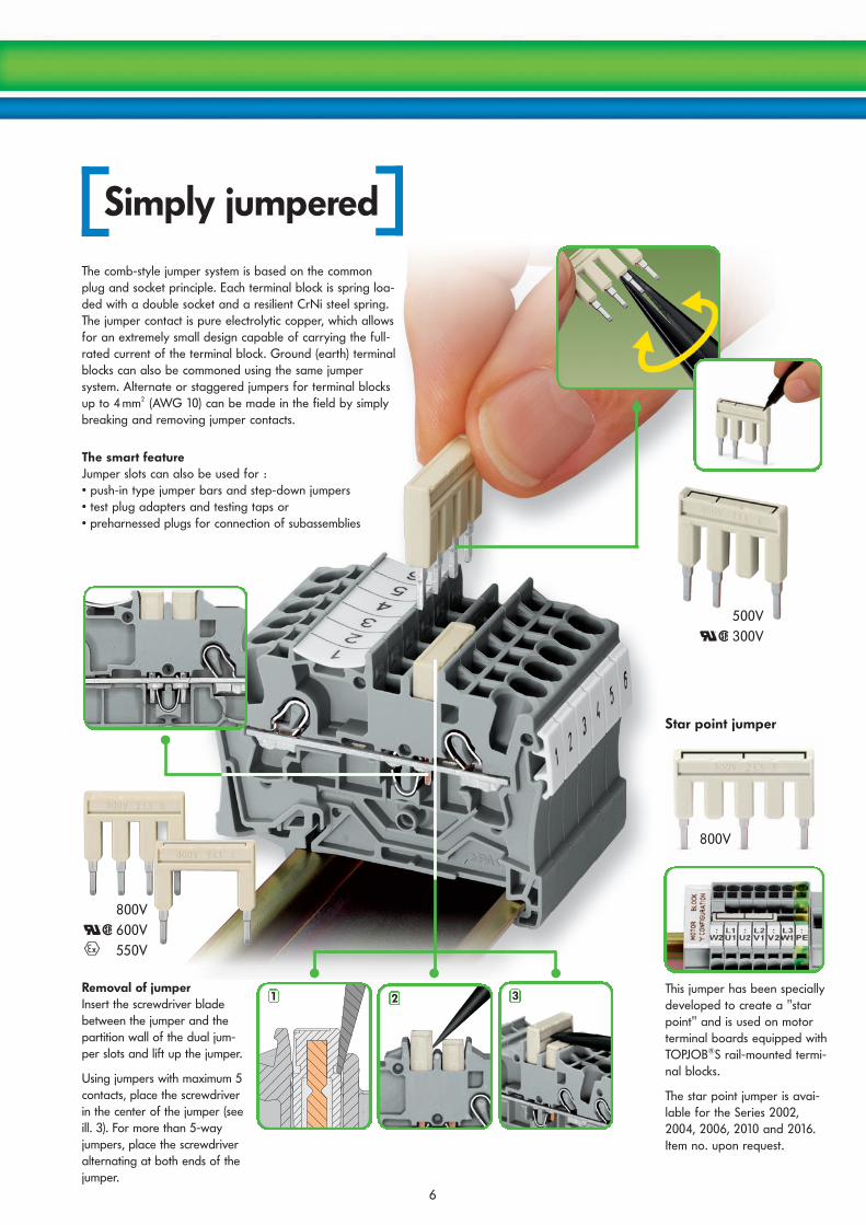
The smart featureJumper slots can also be used for :• push-in type jumper bars and step-down jumpers• test plug adapters and testing taps or• preharnessed plugs for connection of subassemblies
The comb-style jumper system is based on the commonplug and socket principle. Each terminal block is spring loa-ded with a double socket and a resilient CrNi steel spring.The jumper contact is pure electrolytic copper, which allowsfor an extremely small design capable of carrying the full-rated current of the terminal block. Ground (earth) terminalblocks can also be commoned using the same jumpersystem. Alternate or staggered jumpers for terminal blocksup to 4 mm2 (AWG 10) can be made in the field by simplybreaking and removing jumper contacts.
Removal of jumper Insert the screwdriver bladebetween the jumper and thepartition wall of the dual jum-per slots and lift up the jumper.
Using jumpers with maximum 5contacts, place the screwdriverin the center of the jumper (seeill. 3). For more than 5-wayjumpers, place the screwdriveralternating at both ends of thejumper.
Simply jumpered
This jumper has been speciallydeveloped to create a "starpoint" and is used on motorterminal boards equipped withTOPJOB®S rail-mounted termi-nal blocks.
The star point jumper is avai-lable for the Series 2002,2004, 2006, 2010 and 2016.Item no. upon request.
Star point jumper

7
(1) (1)
Simply commoned with staggered jumpers
An end plate (1) must alwaysbe applied between the ter-minal blocks to be commo-ned with step-down jum-pers.
The step-down jumper 2016-499 is suitable for commoning 16 /10 mm2 (AWG 4 /6)terminal blocks with 10 / 6 / 4 / 2.5 mm2 (AWG 6 / 8 / 10 / 12) terminal blocks. The step-down jumper 2006-499 is suitable for commoning 6 / 4 mm2 (AWG 8 / 10)terminal blocks with 4 / 2.5 / 1.5 mm2 (AWG 10 / 12 / 14) terminal blocks.
Note The total current flowing cannot exceedthe rating of the step-down jumper orpush-in type jumper bar.
with push-in type jumper barsWhen commoning on the open side of the block using an end plate, terminal blocks16 mm2 (AWG 4) and 10 mm2 (AWG 6) can be commoned with terminal blocks rated two sizesbelow the rated cross section and terminal blocks 6 (AWG 8) / 4 (AWG 10) and 2.5 mm2
(AWG 12) can be commoned with terminal blocks rated one size below the rated cross section.For example, terminal blocks 16 mm2 (AWG 4) can be commoned with terminal blocks 6 mm2
(AWG 8) (see ill.) or terminal blocks 10 mm2
(AWG 6) with terminal blocks 4 mm2 (AWG 10).
When commoning on the back side of theblock using an end plate, terminal blocks canbe commoned with terminal blocks rated twosizes below the rated cross section. For exam-ple, 16 mm2 (AWG 4) terminal blocks can becommoned with terminal blocks 6 mm2 (AWG 8)or terminal blocks 6 mm2 (AWG 8) with terminalblocks 2.5 mm2 (AWG 12) (see ill.).
Simply jumperedwith step-down jumpers
The special design of the TOPJOB®Sstaggered jumpers allows two jumpers to be used in each jumperslot of the 2002 Series TOPJOB®S rail-mounted terminal blocks and 2003 Series multilevel installation terminal blocks. This means that four different potentials can be commoned simultaneously using rail-mounted terminal blocks with dual jumper slots.
Custom staggered jumpers arecreated by breaking off indivi-dual jumper contacts. Makesure that only one contact lugis in contact with the terminalblock. See also page 28.
Insert the staggered jumpers so that the redlines of both jumpers are facing each other.

8
Modular TOPJOB®S connectorsThe spring-loaded jumper system of the TOPJOB®S rail-mountedterminal blocks is suited for testing accessories like test plug adap-ters and testing taps as well as modular TOPJOB®S connectors.Modular connectors with CAGE CLAMP®S technology offer anadditional connection option for conductors having the same size asthe corresponding rail-mounted terminal block. Additionally, terminal blocks canbe skipped using spacer modules.
ConnectorsConnectors for Series 2001,2002 and 2004 are equip-ped with a Ø 2 mm /0.079 inor Ø 2.3 mm /0.091 in testsocket.
Modular connectors and connector stripsThe modular connectors for the Series 2001, 2002 and2004 are equipped with a Ø 2 mm/0.079 in orØ 2.3 mm/0.091 in test socket.Additionally, 2 to 10-pole connector strips for the Series2001 and 2002 as well as 2 to 5-pole connector stripsfor the Series 2004 are available.
Testing tapTesting tap suited forSeries 2001 to 2016. Indi-vidual test wires up to2.5 mm2 (AWG 12) can beconnected without usingany tools.
Simply testedwith jumper slot for connectors
Note: Disconnected connectorsshould not be live. Furthermore,connectors used according to theregulations should not be connectedor disconnected under load.

9
Simply markedFinding the appropriate marking easily andquickly using WMB markers or continuousmarker strips
Custom rail assemblies and markingscan be designed easily using theWAGO ProServe 4.1 software.
A thermal transfer printer is used to print mar-ker strips (Series 2009) or WMB markers on a continuous reel.
Designing ...
Printing ...
Snapping ...
Three receptacles areavailable for WMB markers on continuous reel.
The marker strip is snapped into thecenter marker receptacle profile.
Combining marker stripsand individual WMBmarkers.
Alternatively, miniatureWSB markers can beprinted using a plotter.
10
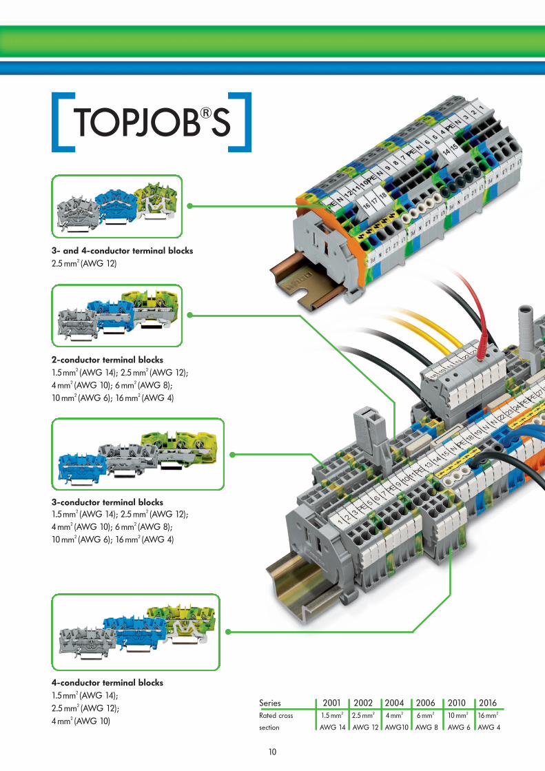
Series 2001 2002 2004 2006 2010 2016Rated cross 1.5 mm2 2.5 mm2 4 mm2 6 mm2 10 mm2 16 mm2
section AWG 14 AWG 12 AWG10 AWG 8 AWG 6 AWG 4
2-conductor terminal blocks1.5mm2 (AWG 14); 2.5 mm2 (AWG 12);4 mm2 (AWG 10); 6 mm2 (AWG 8);10 mm2 (AWG 6); 16 mm2 (AWG 4)
3-conductor terminal blocks1.5mm2 (AWG 14); 2.5 mm2 (AWG 12);4 mm2 (AWG 10); 6 mm2 (AWG 8);10 mm2 (AWG 6); 16 mm2 (AWG 4)
4-conductor terminal blocks1.5mm2 (AWG 14);2.5 mm2 (AWG 12);4 mm2 (AWG 10)
3- and 4-conductor terminal blocks2.5 mm2 (AWG 12)
11
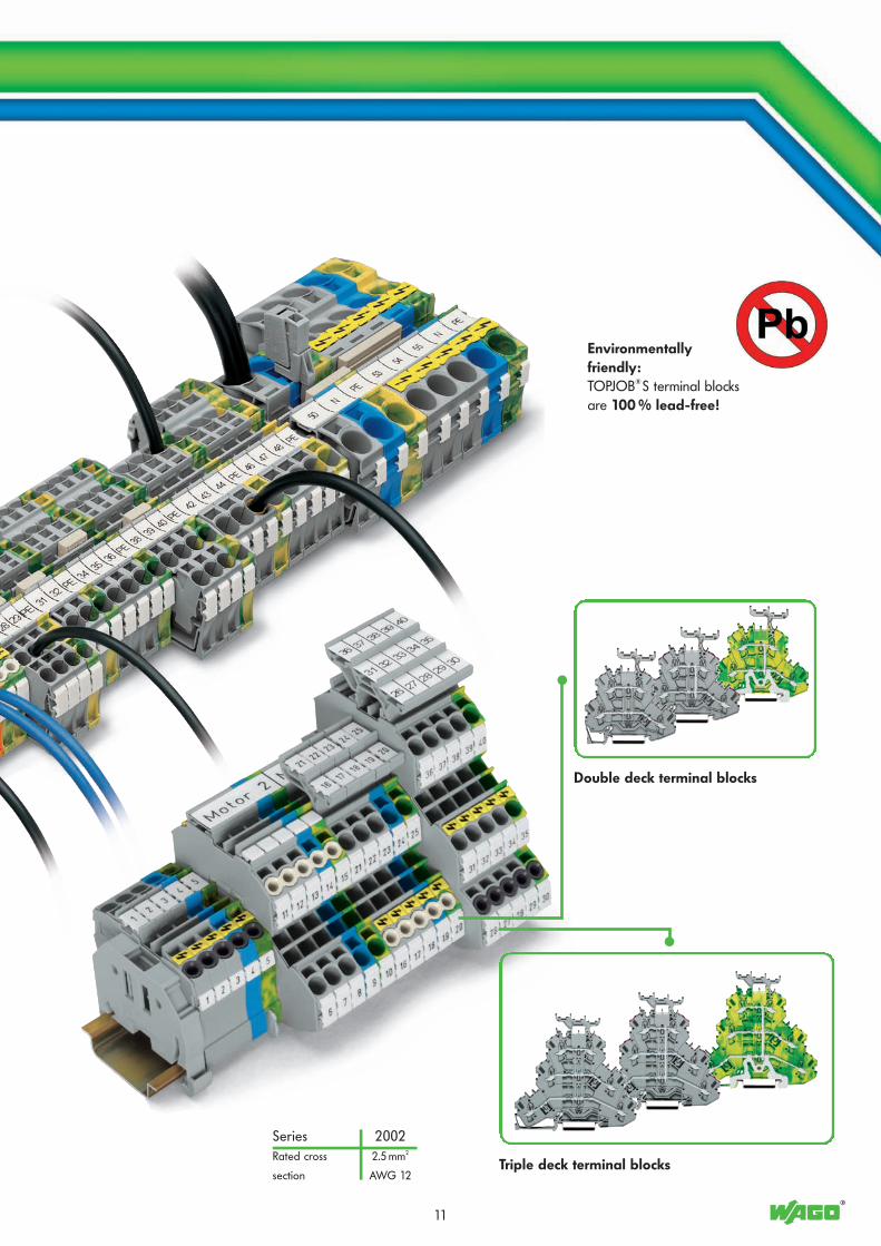
Series 2002Rated cross 2.5 mm2
section AWG 12
Environmentallyfriendly:TOPJOB®S terminal blocksare 100 % lead-free!
Double deck terminal blocks
Triple deck terminal blocks

12
Push-in type jumper bars with breakablecontact lugs offer the same benefits to theTOPJOB®S installation terminal blocks asto the rail-mounted terminal blocks (e.g.individual jumper configuration on site,skipping of potentials, etc.).
The compact busbar carrier, which isplaced every 200 mm, is used to addi-tionally support the busbar on a longassembly.Perforations make it possible to fit thecarrier to all TOPJOB®S installationterminal blocks using a single part.
Each connection point has an individual marker receptacle forWMB markers. Additionally, the upper marker receptacle is sui-table for marker strips that can be marked manually using amarker pen or automatically by a thermal transfer printer.
Screwless N-disconnect slide link forautomatic and safe connection onto theN-busbar by simply sliding the link.
Very compact dimen-sions provide maximumwiring space in stan-dard distribution boxes.The 2003 Series multile-vel installation terminalblocks are the smallestterminal blocks withdirect insertion wireconnection on the mar-ket providing the fullfunctionality of a 4 mm2
terminal block.
The busbar carrier with end stopfunction, which is only 7.5 mmwide can replace end stop.The detachable separator plateon the carrier can be used bothfor separating the differentpotentials of N-busbars that aredirectly next to each other or asa touch-proof end plate for anN-busbar.

13
TOPJOB®S – The range of terminal blocks for alltypes of applications.
● The direct connection of solidwires in small distribution boxessaves time and money.
● Operating errors can be preven-ted as all types of terminal blocksfor building installation are equip-ped with push-in connection tech-nology.
● Terminal blocks for building installation expand circuitdesign possibilities.
● The use of standard accessories reduces order-proces-sing and stock-holding costs.
● A high level of application safety is achieved throughoptimum knowledge of the small range of parts.
● As the position of the busbars is the same, the new TOPJOB®S installation terminal blocks are compatible withstandard topJob installation terminal blocks.
Environmentallyfriendly:TOPJOB®S terminal blocksare 100 % lead-free!
Commoning is done using the new stag-gered jumper system in one singleTOPJOB®S jumper slot. The multilevelinstallation terminal blocks of Series2003 are therefore suitable for use invery confined spaces.
The optional busbar transparent cover (item no. 777-303) protects thebusbar against accidental contact and makes it easy to see which ter-minal blocks are connected to the busbar.
The conductor entry holes of the multi-level installation terminal blocks arecolor marked, providing a clear arran-gement of the terminals.The grounding foot automatically gua-rantees a safe connection to the carrierrail.
Removal of staggered jumpersInsert the screwdriver blade between the jumpers and liftthem up.
14
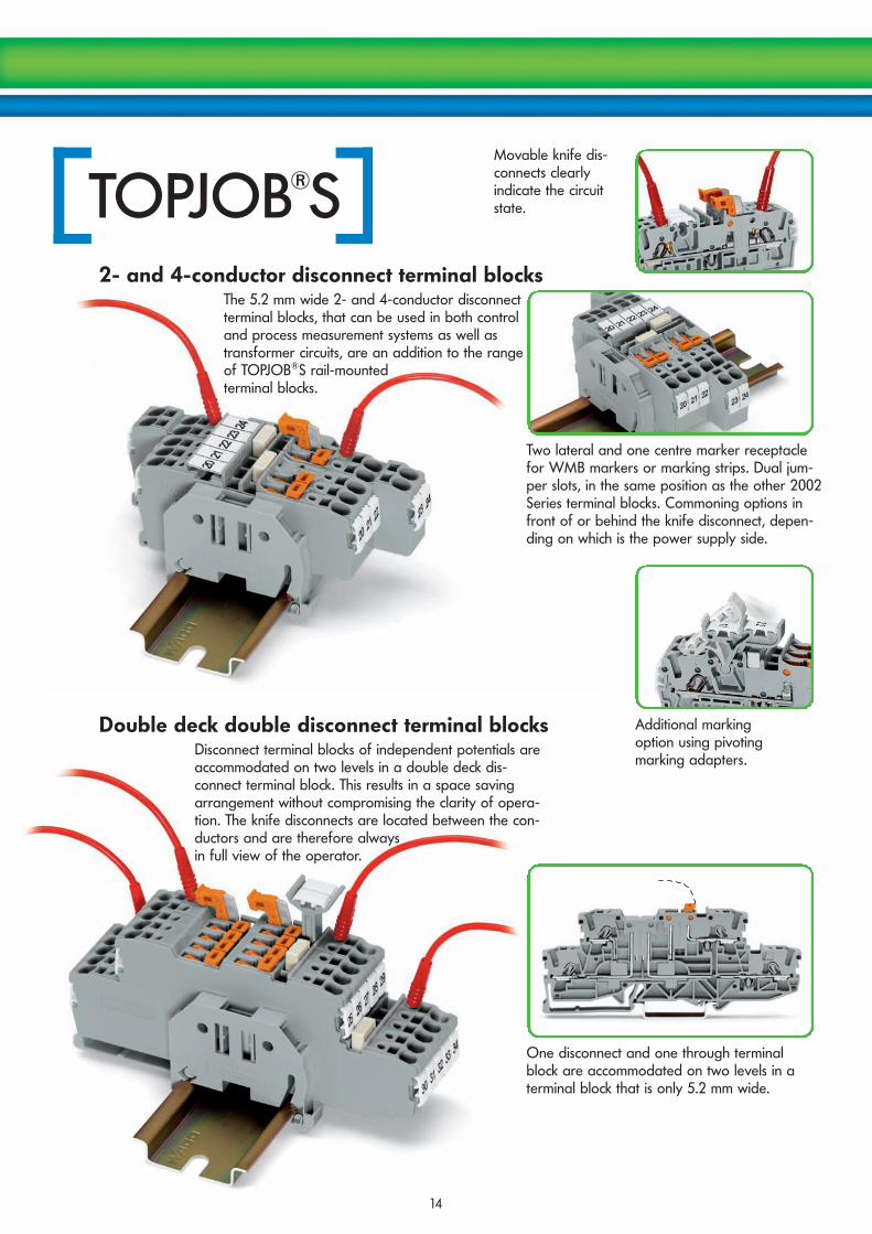
2- and 4-conductor disconnect terminal blocks
Movable knife dis-connects clearlyindicate the circuitstate.
Double deck double disconnect terminal blocks
Two lateral and one centre marker receptaclefor WMB markers or marking strips. Dual jum-per slots, in the same position as the other 2002Series terminal blocks. Commoning options infront of or behind the knife disconnect, depen-ding on which is the power supply side.
The 5.2 mm wide 2- and 4-conductor disconnectterminal blocks, that can be used in both controland process measurement systems as well astransformer circuits, are an addition to the rangeof TOPJOB®S rail-mountedterminal blocks.
Disconnect terminal blocks of independent potentials areaccommodated on two levels in a double deck dis-connect terminal block. This results in a space savingarrangement without compromising the clarity of opera-tion. The knife disconnects are located between the con-ductors and are therefore alwaysin full view of the operator.
Additional marking option using pivoting marking adapters.
One disconnect and one through terminal block are accommodated on two levels in a terminal block that is only 5.2 mm wide.

15
+ + + + –
Double deck diode terminal blocks
These double and triple deck diode terminalblocks have been specially developed for customdiode circuits such as lamp test and collectivefault signal circuits.Using LED terminal blocks, monitoring units canbe designed for control and operating circuits.The terminal blocks provide high density wiringmaintaining a width of only 5.2 mm.Using push-in type jumper bars opens up addi-tional possibilities when designing custom circuits.
Triple deck diode terminal blocks
Lamp test circuit
Open diode gate, can be connected individually. Using push-in type jumper bars,individual levels can be turned into polarized diode gates.
*U24*U24 *U24
16
4 4 4
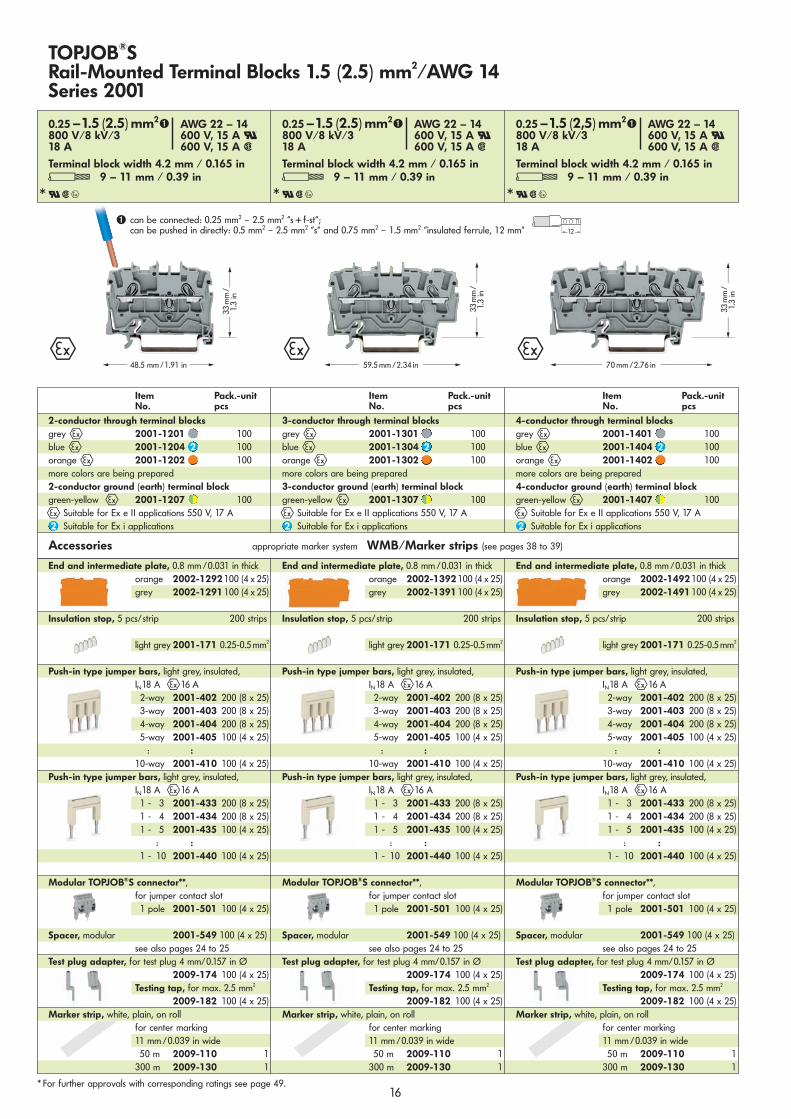
TOPJOB®S Rail-Mounted Terminal Blocks 1.5 (2.5) mm2/AWG 14Series 2001
<____________ 70 mm /2.76 in ____________><____ 48.5 mm /1.91 in ____> <_______ 59.5 mm /2.34 in ________>
* For further approvals with corresponding ratings see page 49.
Accessories appropriate marker system WMB/Marker strips (see pages 38 to 39)
Item Pack.-unitNo. pcs
Item Pack.-unitNo. pcs
Item Pack.-unitNo. pcs
4-conductor through terminal blocksgrey 4 2001-1401 100blue 4 2001-1404 100orange4 2001-1402 100more colors are being prepared4-conductor ground (earth) terminal blockgreen-yellow 4 2001-1407 100
4 Suitable for Ex e II applications 550 V, 17 ASuitable for Ex i applications
3-conductor through terminal blocksgrey 4 2001-1301 100blue 4 2001-1304 100orange4 2001-1302 100more colors are being prepared3-conductor ground (earth) terminal blockgreen-yellow 4 2001-1307 100
4 Suitable for Ex e II applications 550 V, 17 ASuitable for Ex i applications
2-conductor through terminal blocksgrey 4 2001-1201 100blue 4 2001-1204 100orange4 2001-1202 100more colors are being prepared2-conductor ground (earth) terminal blockgreen-yellow 4 2001-1207 100
4 Suitable for Ex e II applications 550 V, 17 ASuitable for Ex i applications
End and intermediate plate, 0.8 mm /0.031 in thickorange 2002-1492100 (4 x 25)grey 2002-1491100 (4 x 25)
Insulation stop, 5 pcs/strip 200 strips
light grey 2001-171 0.25-0.5mm2
Push-in type jumper bars, light grey, insulated,IN18 A 416 A2-way 2001-402 200 (8 x 25)3-way 2001-403 200 (8 x 25)4-way 2001-404 200 (8 x 25)5-way 2001-405 100 (4 x 25)
: :10-way 2001-410 100 (4 x 25)
Push-in type jumper bars, light grey, insulated,IN18 A 416 A 1 - 3 2001-433 200 (8 x 25)1 - 4 2001-434 200 (8 x 25)1 - 5 2001-435 100 (4 x 25)
: :1 - 10 2001-440 100 (4 x 25)
Modular TOPJOB®S connector**,for jumper contact slot 1 pole 2001-501 100 (4 x 25)
Spacer, modular 2001-549 100 (4 x 25)see also pages 24 to 25
Test plug adapter, for test plug 4 mm/0.157 in Ø 2009-174 100 (4 x 25)
Testing tap, for max. 2.5 mm2
2009-182 100 (4 x 25)Marker strip, white, plain, on roll
for center marking 11 mm /0.039 in wide50 m 2009-110 1
300 m 2009-130 1
End and intermediate plate, 0.8 mm /0.031 in thickorange 2002-1392100 (4 x 25)grey 2002-1391100 (4 x 25)
Insulation stop, 5 pcs/strip 200 strips
light grey 2001-171 0.25-0.5mm2
Push-in type jumper bars, light grey, insulated,IN18 A 416 A2-way 2001-402 200 (8 x 25)3-way 2001-403 200 (8 x 25)4-way 2001-404 200 (8 x 25)5-way 2001-405 100 (4 x 25)
: :10-way 2001-410 100 (4 x 25)
Push-in type jumper bars, light grey, insulated,IN18 A 416 A 1 - 3 2001-433 200 (8 x 25)1 - 4 2001-434 200 (8 x 25)1 - 5 2001-435 100 (4 x 25)
: :1 - 10 2001-440 100 (4 x 25)
Modular TOPJOB®S connector**,for jumper contact slot 1 pole 2001-501 100 (4 x 25)
Spacer, modular 2001-549 100 (4 x 25)see also pages 24 to 25
Test plug adapter, for test plug 4 mm/0.157 in Ø 2009-174 100 (4 x 25)
Testing tap, for max. 2.5 mm2
2009-182 100 (4 x 25)Marker strip, white, plain, on roll
for center marking 11 mm /0.039 in wide50 m 2009-110 1
300 m 2009-130 1
End and intermediate plate, 0.8 mm /0.031 in thickorange 2002-1292100 (4 x 25)grey 2002-1291100 (4 x 25)
Insulation stop, 5 pcs/strip 200 strips
light grey 2001-171 0.25-0.5mm2
Push-in type jumper bars, light grey, insulated,IN18 A 416 A2-way 2001-402 200 (8 x 25)3-way 2001-403 200 (8 x 25)4-way 2001-404 200 (8 x 25)5-way 2001-405 100 (4 x 25)
: :10-way 2001-410 100 (4 x 25)
Push-in type jumper bars, light grey, insulated,IN18 A 416 A 1 - 3 2001-433 200 (8 x 25)1 - 4 2001-434 200 (8 x 25)1 - 5 2001-435 100 (4 x 25)
: :1 - 10 2001-440 100 (4 x 25)
Modular TOPJOB®S connector**,for jumper contact slot 1 pole 2001-501 100 (4 x 25)
Spacer, modular 2001-549 100 (4 x 25)see also pages 24 to 25
Test plug adapter, for test plug 4 mm/0.157 in Ø 2009-174 100 (4 x 25)
Testing tap, for max. 2.5 mm2
2009-182 100 (4 x 25)Marker strip, white, plain, on roll
for center marking 11 mm /0.039 in wide50 m 2009-110 1
300 m 2009-130 1
➊ can be connected: 0.25 mm2 – 2.5 mm2 “s + f-st“;can be pushed in directly: 0.5 mm2 – 2.5 mm2 “s“ and 0.75 mm2 – 1.5 mm2 “insulated ferrule, 12 mm“
0.25 –1.5 (2.5) mm2➊ AWG 22 – 14800 V/8 kV/3 600 V, 15 A U18 A 600 V, 15 A 2
Terminal block width 4.2 mm / 0.165 inL 9 – 11 mm / 0.39 in
0.25 –1.5 (2.5) mm2➊ AWG 22 – 14800 V/8 kV/3 600 V, 15 A U18 A 600 V, 15 A 2
Terminal block width 4.2 mm / 0.165 inL 9 – 11 mm / 0.39 in
0.25 –1.5 (2,5) mm2➊ AWG 22 – 14800 V/8 kV/3 600 V, 15 A U18 A 600 V, 15 A 2
Terminal block width 4.2 mm / 0.165 inL 9 – 11 mm / 0.39 in
<___
33m
m/___>
1.3
in
<___
33m
m/___>
1.3
in
<___
33m
m/ ___>
1.3
in<_12_>

*U24*U24 *U24
17
4 4 4<____ 48.5 mm /1.91 in ____> <________ 59.5 mm /2.34 in _________> <_____________ 70 mm /2.76 in _____________>
* For further approvals with corresponding ratings see page 49.
Accessories appropriate marker system WMB/Marker strips (see pages 38 to 39)
End and intermediate plate, 0.8 mm /0.031 in thickorange 2002-1492100 (4 x 25)grey 2002-1491100 (4 x 25)
Insulation stop, 5 pcs/strip 200 strips
light grey 2002-171 0.25-0.5 mm2
dark grey2002-172 0.75-1 mm2
Push-in type jumper bars, light grey, insulated,IN 25 A 4 20 A2-way 2002-402 200 (8 x 25)3-way 2002-403 200 (8 x 25)4-way 2002-404 200 (8 x 25)
: :10-way 2002-410 100 (4 x 25)
Staggered jumper, see page 28Push-in type jumper bars, light grey, insulated,
IN 25 A 4 20 A1 - 3 2002-433 200 (8 x 25)1 - 4 2002-434 200 (8 x 25)1 - 5 2002-435 100 (4 x 25)
: :1 - 10 2002-440 100 (4 x 25)
Protective warning marker,for 5 terminal blocksyellow 2002-115 100 (4 x 25)
Modular TOPJOB®S connector**,for jumper contact slot 1 pole 2002-511 100 (4 x 25)
Spacer, modular 2002-549 100 (4 x 25)see also pages 24 to 25
Test plug adapter, for test plug 4 mm/0.157 in Ø 2009-174 100 (4 x 25)
Testing tap, for max. 2.5 mm2
2009-182 100 (4 x 25)
End and intermediate plate, 0.8 mm /0.031 in thickorange 2002-1392100 (4 x 25)grey 2002-1391100 (4 x 25)
Insulation stop, 5 pcs/strip 200 strips
light grey 2002-171 0.25-0.5 mm2
dark grey2002-172 0.75-1 mm2
Push-in type jumper bars, light grey, insulated,IN 25 A 4 20 A2-way 2002-402 200 (8 x 25)3-way 2002-403 200 (8 x 25)4-way 2002-404 200 (8 x 25)
: :10-way 2002-410 100 (4 x 25)
Staggered jumper, see page 28Push-in type jumper bars, light grey, insulated,
IN 25 A 4 20 A1 - 3 2002-433 200 (8 x 25)1 - 4 2002-434 200 (8 x 25)1 - 5 2002-435 100 (4 x 25)
: :1 - 10 2002-440 100 (4 x 25)
Protective warning marker,for 5 terminal blocksyellow 2002-115 100 (4 x 25)
Modular TOPJOB®S connector**,for jumper contact slot 1 pole 2002-511 100 (4 x 25)
Spacer, modular 2002-549 100 (4 x 25)see also pages 24 to 25
Test plug adapter, for test plug 4 mm/0.157 in Ø 2009-174 100 (4 x 25)
Testing tap, for max. 2.5 mm2
2009-182 100 (4 x 25)
End and intermediate plate, 0.8 mm /0.031 in thickorange 2002-1292100 (4 x 25)grey 2002-1291100 (4 x 25)
Insulation stop, 5 pcs/strip 200 strips
light grey 2002-171 0.25-0.5 mm2
dark grey2002-172 0.75-1 mm2
Push-in type jumper bars, light grey, insulated,IN 25 A 4 20 A2-way 2002-402 200 (8 x 25)3-way 2002-403 200 (8 x 25)4-way 2002-404 200 (8 x 25)
: :10-way 2002-410 100 (4 x 25)
Staggered jumper, see page 28Push-in type jumper bars, light grey, insulated,
IN 25 A 4 20 A1 - 3 2002-433 200 (8 x 25)1 - 4 2002-434 200 (8 x 25)1 - 5 2002-435 100 (4 x 25)
: :1 - 10 2002-440 100 (4 x 25)
Protective warning marker,for 5 terminal blocksyellow 2002-115 100 (4 x 25)
Modular TOPJOB®S connector**,for jumper contact slot 1 pole 2002-511 100 (4 x 25)
Spacer, modular 2002-549 100 (4 x 25)see also pages 24 to 25
Test plug adapter, for test plug 4 mm/0.157 in Ø 2009-174 100 (4 x 25)
Testing tap, for max. 2.5 mm2
2009-182 100 (4 x 25)
Item Pack.-unitNo. pcs
Item Pack.-unitNo. pcs
Item Pack.-unitNo. pcs
TOPJOB®S Rail-Mounted Terminal Blocks 2.5 (4) mm2/AWG 12Series 2002
4-conductor through terminal blocksgrey 4 2002-1401 100blue 4 2002-1404 100orange4 2002-1402 100more colors are being prepared4-conductor ground (earth) terminal blockgreen-yellow 4 2002-1407 100
4Suitable for Ex e II applications 550 V, 22 ASuitable for Ex i applications
3-conductor through terminal blocksgrey 4 2002-1301 100blue 4 2002-1304 100orange4 2002-1302 100more colors are being prepared3-conductor ground (earth) terminal blockgreen-yellow 4 2002-1307 100
4Suitable for Ex e II applications 550 V, 22 ASuitable for Ex i applications
2-conductor through terminal blocksgrey 4 2002-1201 100blue 4 2002-1204 100orange4 2002-1202 100more colors are being prepared2-conductor ground (earth) terminal blockgreen-yellow 4 2002-1207 100
4 Suitable for Ex e II applications 550 V, 22 ASuitable for Ex i applications
➊ can be connected: 0.25 mm2 – 4 mm2 “s + f-st“;can be pushed in directly: 0.75 mm2 – 4 mm2 “s“ and 0.75 mm2 – 2.5 mm2 “insulated ferrule, 12 mm“
0.25 – 2.5 (4) mm2➊ AWG 22 – 12800 V/8 kV/3 600 V, 20 A U24 A 600 V, 20 A 2
Terminal block width 5.2 mm / 0.205 inL 10 – 12 mm / 0.43 in
0.25 – 2.5 (4) mm2➊ AWG 22 – 12800 V/8 kV/3 600 V, 20 A U24 A 600 V, 20 A 2
Terminal block width 5.2 mm / 0.205 inL 10 – 12 mm / 0.43 in
0.25 – 2.5 (4) mm2➊ AWG 22 – 12800 V/8 kV/3 600 V, 20 A U24 A 600 V, 20 A 2
Terminal block width 5.2 mm / 0.205 inL 10 – 12 mm / 0.43 in
<___
33m
m/___>
1.3
in
<___
33m
m/___>
1.3
in
<___
33m
m/___>
1.3
in
<_12_>

*U24*U24 *U24
18
4 4 4<____ 52.5 mm /2.07 in ____> <________ 65.5 mm /2.58 in ________> <_____________ 79 mm /3.11 in _____________>
Accessories appropriate marker system WMB/Marker strips/WMB Inline (see pages 38 to 39)
End and intermediate plate, 1 mm /0.039 in thickorange 2004-1492100 (4 x 25)grey 2004-1491100 (4 x 25)
Insulation stop, 5 pcs/strip 200 strips
light grey 2004-171 0.25-0.5 mm2
dark grey2004-172 0.75-1 mm2
Push-in type jumper bars, light grey, insulated, IN 32A
4 30 A2-fach 2004-402 100 (4 x 25)3-fach 2004-403 100 (4 x 25)4-fach 2004-404 100 (4 x 25)5-fach 2004-405 50 (2 x 25)
: :10-fach 2004-410 50 (2 x 25)
Push-in type jumper bars, light grey, insulated, IN 32A
4 30 A1 - 3 2004-433 100 (4 x 25)1 - 4 2004-434 100 (4 x 25)1 - 5 2004-435 50 (2 x 25)
: :1 - 10 2004-440 50 (2 x 25)
Protective warning marker,for 5 terminal blocksyellow 2004-115 100 (4 x 25)
Modular TOPJOB®S connector**,for jumper contact slot 1 pole 2004-511 100 (4 x 25)
Spacer, modular 2004-549 100 (4 x 25)see also pages 24 to 25
Test plug adapter, for test plug 4 mm/0.157 in Ø 2009-174 100 (4 x 25)
Testing tap, for max. 2.5 mm2
2009-182 100 (4 x 25)
End and intermediate plate, 1 mm /0.039 in thickorange 2004-1392100 (4 x 25)grey 2004-1391100 (4 x 25)
Insulation stop, 5 pcs/strip 200 strips
light grey 2004-171 0.25-0.5 mm2
dark grey2004-172 0.75-1 mm2
Push-in type jumper bars, light grey, insulated, IN 32A
4 30 A2-fach 2004-402 100 (4 x 25)3-fach 2004-403 100 (4 x 25)4-fach 2004-404 100 (4 x 25)5-fach 2004-405 50 (2 x 25)
: :10-fach 2004-410 50 (2 x 25)
Push-in type jumper bars, light grey, insulated, IN 32A
4 30 A1 - 3 2004-433 100 (4 x 25)1 - 4 2004-434 100 (4 x 25)1 - 5 2004-435 50 (2 x 25)
: :1 - 10 2004-440 50 (2 x 25)
Protective warning marker,for 5 terminal blocksyellow 2004-115 100 (4 x 25)
Modular TOPJOB®S connector**,for jumper contact slot 1 pole 2004-511 100 (4 x 25)
Spacer, modular 2004-549 100 (4 x 25)see also pages 24 to 25
Test plug adapter, for test plug 4 mm/0.157 in Ø 2009-174 100 (4 x 25)
Testing tap, for max. 2.5 mm2
2009-182 100 (4 x 25)
End and intermediate plate, 1 mm /0.039 in thickorange 2004-1292100 (4 x 25)grey 2004-1291100 (4 x 25)
Insulation stop, 5 pcs/strip 200 strips
light grey 2004-171 0.25-0.5 mm2
dark grey2004-172 0.75-1 mm2
Push-in type jumper bars, light grey, insulated, IN 32A
4 30 A2-fach 2004-402 100 (4 x 25)3-fach 2004-403 100 (4 x 25)4-fach 2004-404 100 (4 x 25)5-fach 2004-405 50 (2 x 25)
: :10-fach 2004-410 50 (2 x 25)
Push-in type jumper bars, light grey, insulated, IN 32A
4 30 A1 - 3 2004-433 100 (4 x 25)1 - 4 2004-434 100 (4 x 25)1 - 5 2004-435 50 (2 x 25)
: :1 - 10 2004-440 50 (2 x 25)
Protective warning marker,for 5 terminal blocksyellow 2004-115 100 (4 x 25)
Modular TOPJOB®S connector**,for jumper contact slot 1 pole 2004-511 100 (4 x 25)
Spacer, modular 2004-549 100 (4 x 25)see also pages 24 to 25
Test plug adapter, for test plug 4 mm/0.157 in Ø 2009-174 100 (4 x 25)
Testing tap, for max. 2.5 mm2
2009-182 100 (4 x 25)
4-conductor through terminal blocksgrey 4 2004-1401 50blue 4 2004-1404 50orange4 2004-1402 50weitere Farbvarianten in Vorbereitung4-conductor ground (earth) terminal blockgreen-yellow 2004-1407 50
4 Suitable for Ex e II applications 550 V, 30 ASuitable for Ex i applications
3-conductor through terminal blocksgrey 4 2004-1301 50blue 4 2004-1304 50orange4 2004-1302 50weitere Farbvarianten in Vorbereitung3-conductor ground (earth) terminal blockgreen-yellow 4 2004-1307 50
4 Suitable for Ex e II applications 550 V, 30 ASuitable for Ex i applications
2-conductor through terminal blocksgrey 4 2004-1201 50blue 4 2004-1204 50orange4 2004-1202 50weitere Farbvarianten in Vorbereitung2-conductor ground (earth) terminal blockgreen-yellow 4 2004-1207 50
4 Suitable for Ex e II applications 550 V, 30 ASuitable for Ex i applications
Item Pack.-unitNo. pcs
Item Pack.-unitNo. pcs
Item Pack.-unitNo. pcs
TOPJOB®S Rail-Mounted Terminal Blocks 4 (6) mm2/AWG 10Series 2004
* For further approvals with corresponding ratings see page 49.
➊ can be connected: 0.5 mm2 – 6 mm2 “s + f-st“;can be pushed in directly: 1 mm2 – 6 mm2 “s“ and 0.75 mm2 – 4 mm2 “insulated ferrule, 12 mm“
0.5 – 4 (6) mm2➊ AWG 20 – 10800 V/8 kV/3 600 V, 30 A U32 A 600 V, 30 A 2
Terminal block width 6.2 mm / 0.244 inL 11 – 13 mm / 0.47 in
0.5 – 4 (6) mm2➊ AWG 20 – 10800 V/8 kV/3 600 V, 30 A U32 A 600 V, 30 A 2
Terminal block width 6.2 mm / 0.244 inL 11 – 13 mm / 0.47 in
0.5 – 4 (6) mm2➊ AWG 20 – 10800 V/8 kV/3 600 V, 30 A U32 A 600 V, 30 A 2
Terminal block width 6.2 mm / 0.244 inL 11 – 13 mm / 0.47 in
<___
33m
m/___>
1.3
in
<___
33m
m/___>
1.3
in
<___
33m
m/___>
1.3
in
<_12_>

*U24*U24
19
4 4
TOPJOB®S Rail-Mounted Terminal Blocks 6 (10) mm2/AWG 8Series 2006
* For further approvals with corresponding ratings see page 49.
Accessories appropriate marker system WMB/Marker strips/WMB Inline (see pages 38 to 39)
End and intermediate plate, 1 mm /0.039 in thickorange 2006-1392100 (4 x 25)grey 2006-1391100 (4 x 25)
Push-in type jumper bars, light grey, insulated, IN 41A
4 33 A2-way 2006-402 50 (2 x 25)3-way 2006-403 50 (2 x 25)4-way 2006-404 50 (2 x 25)5-way 2006-405 50 (2 x 25)
Push-in type jumper bars, light grey, insulated, IN 41A
4 33 A1 - 3 2006-433 50 (2 x 25)1 - 4 2006-434 50 (2 x 25)1 - 5 2006-435 50 (2 x 25)
Protective warning marker,for 5 terminal blocksyellow 2006-115 100 (4 x 25)
Test plug adapter, for test plug 4 mm/0.157 in Ø 2009-174 100 (4 x 25)
Testing tap, for max. 2.5 mm2
2009-182 100 (4 x 25)Marker strip, white, plain, on roll
for center marking 11 mm /0.039 in wide50 m 2009-110 1
300 m 2009-130 1
End and intermediate plate, 1 mm /0.039 in thickorange 2006-1292100 (4 x 25)grey 2006-1291100 (4 x 25)
Push-in type jumper bars, light grey, insulated, IN 41A
4 33 A2-way 2006-402 50 (2 x 25)3-way 2006-403 50 (2 x 25)4-way 2006-404 50 (2 x 25)5-way 2006-405 50 (2 x 25)
Push-in type jumper bars, light grey, insulated, IN 41A
4 33 A1 - 3 2006-433 50 (2 x 25)1 - 4 2006-434 50 (2 x 25)1 - 5 2006-435 50 (2 x 25)
Protective warning marker,for 5 terminal blocksyellow 2006-115 100 (4 x 25)
Test plug adapter, for test plug 4 mm/0.157 in Ø 2009-174 100 (4 x 25)
Testing tap, for max. 2.5 mm2
2009-182 100 (4 x 25)Marker strip, white, plain, on roll
for center marking 11 mm /0.039 in wide50 m 2009-110 1
300 m 2009-130 1
3-conductor through terminal blocksgrey 4 2006-1301 25blue 4 2006-1304 25orange4 2006-1302 25
3-conductor ground (earth) terminal blockgreen-yellow 4 2006-1307 25
4 Suitable for Ex e II applications 550 V, 36 ASuitable for Ex i applications
2-conductor through terminal blocksgrey 4 2006-1201 50blue 4 2006-1204 50orange4 2006-1202 50
2-conductor ground (earth) terminal blockgreen-yellow 4 2006-1207 50
4 Suitable for Ex e II applications 550 V, 38 ASuitable for Ex i applications
Item Pack.-unitNo. pcs
Item Pack.-unitNo. pcs
<_____ 57.5 mm /2.26 in ______> <____________ 73.5 mm /2.89 in ___________>
Note:The total current flowing cannot exceed therating of the step-down jumper/push-intype jumper bar.
Commoning with step-down jumpers
Application notes see page 7
Step-down jumper, light grey, insulated32 A 2006-499 50 (2 x 25)
➊ can be connected: 0.5 mm2 – 10 mm2 “s + f-st“;can be pushed in directly: 1.5 mm2 – 10 mm2 “s“ and1.5 mm2 – 6 mm2 “insulated ferrule, 12 mm“
0.5 – 6 (10) mm2➊ AWG 20 – 8800 V/8 kV/3 600 V, 50 A U41 A 600 V, 50 A 2
Terminal block width 7.5 mm / 0.295 inL 13 – 15 mm / 0.55 in
0.5 – 6 (10) mm2➊ AWG 20 – 8800 V/8 kV/3 600 V, 50 A U41 A 600 V, 50 A 2
Terminal block width 7.5 mm / 0.295 inL 13 – 15 mm / 0.55 in
<___
33m
m/___>
1.3
in
<___
33m
m/___>
1.3
in
Item Pack.-unitNo. pcs
Commoning with step-down jumpersAn end plate must always be used between the terminalblocks that are commoned with step-down jumpers.Step-down jumper 2006-499 is suitable for commoningAWG 10/12 (6/4 mm2) terminal blocks with AWG12/14/16 (4/2.5/1.5 mm2) terminal blocks.
Step-down jumpers are simply pushed down to full inser-tion, in the same way as all other push-in type jumper bars.
<_12_>

*U24*U24
20
4 4
* For further approvals with corresponding ratings see page 49.
TOPJOB®S Rail-Mounted Terminal Blocks 10 (16) mm2/AWG 6Series 2010
Accessories appropriate marker system WMB/Marker strips/WMB Inline (see pages 38 to 39)
Step-down jumper, light grey, insulated57 A2016-499 50 (2 x 25)
End and intermediate plate, 1 mm /0.039 in thickorange 2010-1392100 (4 x 25)grey 2010-1391100 (4 x 25)
Push-in type jumper bars, light grey, insulated, IN 57 A
4 50 A2-way 2010-402 50 (2 x 25)3-way 2010-403 50 (2 x 25)4-way 2010-404 50 (2 x 25)5-way 2010-405 50 (2 x 25)
Push-in type jumper bars, light grey, insulated, IN 57 A
4 50 A1 - 3 2010-433 50 (2 x 25)1 - 4 2010-434 50 (2 x 25)1 - 5 2010-435 50 (2 x 25)
Protective warning marker,for 5 terminal blocksyellow 2010-115 100 (4 x 25)
Test plug adapter, for test plug 4 mm/0.157 in Ø 2009-174 100 (4 x 25)
Testing tap, for max. 2.5 mm2
2009-182 100 (4 x 25)Marker strip, white, plain, on roll
for center marking 11 mm /0.039 in wide50 m 2009-110 1
300 m 2009-130 1
Finger guard cover,serves as touchproof protection for unused clamping unitsyellow 2010-100 100 (4 x 25)
End and intermediate plate, 1 mm /0.039 in thickorange 2010-1292100 (4 x 25)grey 2010-1291100 (4 x 25)
Push-in type jumper bars, light grey, insulated, IN 57 A
4 51 A2-way 2010-402 50 (2 x 25)3-way 2010-403 50 (2 x 25)4-way 2010-404 50 (2 x 25)5-way 2010-405 50 (2 x 25)
Push-in type jumper bars, light grey, insulated, IN 57 A
4 51 A1 - 3 2010-433 50 (2 x 25)1 - 4 2010-434 50 (2 x 25)1 - 5 2010-435 50 (2 x 25)
Protective warning marker,for 5 terminal blocksyellow 2010-115 100 (4 x 25)
Test plug adapter, for test plug 4 mm/0.157 in Ø 2009-174 100 (4 x 25)
Testing tap, for max. 2.5 mm2
2009-182 100 (4 x 25)Marker strip, white, plain, on roll
for center marking 11 mm /0.039 in wide50 m 2009-110 1
300 m 2009-130 1
Finger guard cover,serves as touchproof protection for unused clamping unitsyellow 2010-100 100 (4 x 25)
Commoning with step-down jumpersAn end plate must always be used between the terminalblocks that are commoned with step-down jumpers.Step-down jumper 2006-499 is suitable for commoningAWG 10/12 (6/4 mm2) terminal blocks with AWG12/14/16 (4/2.5/1.5 mm2) terminal blocks.
Step-down jumpers are simply pushed down to full inser-tion, in the same way as all other push-in type jumper bars.
3-conductor through terminal blocksgrey 4 2010-1301 25blue 4 2010-1304 25orange4 2010-1302 25
3-conductor ground (earth) terminal blockgreen-yellow 4 2010-1307 25
4 Suitable for Ex e II applications 550 V, 50 ASuitable for Ex i applications
2-conductor through terminal blocksgrey4 2010-1201 25blue 4 2010-1204 25orange4 2010-1202 25
2-conductor ground (earth) terminal blockgreen-yellow 4 2010-1207 25
4 Suitable for Ex e II applications 550 V, 51 ASuitable for Ex i applications
Item Pack.-unitNo. pcs
Item Pack.-unitNo. pcs
<________ 68 mm /2.68 in _________> <_________________ 89 mm /3.5 in __________________>
Commoning with step-down jumpers
Application notes see page 7
➊ can be connected: 0.5 mm2 – 16 mm2 “s + f-st“;can be pushed in directly: 2.5 mm2 – 16 mm2 “s“ and2.5 mm2 – 10 mm2 “insulated ferrule, 18 mm“
0.5 – 10 (16) mm2➊ AWG 20 – 6800 V/8 kV/3 600 V, 65 A U57 A 600 V, 65 A 2
Terminal block width 10 mm / 0.394 inL 17 – 19 mm / 0.71 in
0.5 – 10 (16) mm2➊ AWG 20 – 6800 V/8 kV/3 600 V, 65 A U57 A 600 V, 65 A 2
Terminal block width 10 mm / 0.394 inL 17 – 19 mm / 0.71 in
<___
37m
m/___>
1.46
in
<___
37m
m/___>
1.46
in
Item Pack.-unitNo. pcs
<_18_>
Note:The total current flowing cannot exceed therating of the step-down jumper/push-intype jumper bar.
Finger guard cover snapped into unused clamping unit(Example: Series 2016)

*U24*U24
21
4 4
* For further approvals with corresponding ratings see page 49.
<___________ 70 mm /2.76 in _________> <_________________ 92 mm /3.62 in ___________________>
End and intermediate plate, 1 mm /0.039 in thickorange 2016-1292100 (4 x 25)grey 2016-1291100 (4 x 25)
Push-in type jumper bars, light grey, insulated, IN 76 A
4 65 A2-way 2016-402 50 (2 x 25)3-way 2016-403 50 (2 x 25)4-way 2016-404 50 (2 x 25)5-way 2016-405 50 (2 x 25)
Push-in type jumper bars, light grey, insulated, IN 76 A
4 65 A1 - 3 2016-433 50 (2 x 25)1 - 4 2016-434 50 (2 x 25)1 - 5 2016-435 50 (2 x 25)
Protective warning marker,for 5 terminal blocksyellow 2016-115 50 (2 x 25)
Test plug adapter, for test plug 4 mm/0.157 in Ø 2009-174 100 (4 x 25)
Testing tap, for max. 2.5 mm2
2009-182 100 (4 x 25)Marker strip, white, plain, on roll
for center marking 11 mm /0.039 in wide50 m 2009-110 1
300 m 2009-130 1
Finger guard cover,serves as touchproof protection for unused clamping unitsyellow 2016-100 100 (4 x 25)
Commoning with step-down jumpersAn end plate must always be used between the terminalblocks that are commoned with step-down jumpers.Step-down jumper 2006-499 is suitable for commoningAWG 10/12 (6/4 mm2) terminal blocks with AWG12/14/16 (4/2.5/1.5 mm2) terminal blocks.
Step-down jumpers are simply pushed down to full inser-tion, in the same way as all other push-in type jumper bars.
3-conductor through terminal blocksgrey 4 2016-1301 20blue 4 2016-1304 20orange4 2016-1302 20
3-conductor ground (earth) terminal blockgreen-yellow 4 2016-1307 20
4 Suitable for Ex e II applications 550 V, 67 ASuitable for Ex i applications
2-conductor through terminal blocksgrey 4 2016-1201 20blue 4 2016-1204 20orange4 2016-1202 20
2-conductor ground (earth) terminal blockgreen-yellow 4 2016-1207 20
4 Suitable for Ex e II applications 550 V, 70 ASuitable for Ex i applications
Item Pack.-unitNo. pcs
Item Pack.-unitNo. pcs
<___
37m
m/___>
1.46
in
<___
37m
m/___>
1.46
in
TOPJOB®S Rail-Mounted Terminal Blocks 16 (25 ”f-st”) mm2/AWG 4Series 2016
Accessories appropriate marker system WMB/Marker strips/WMB Inline (see pages 38 to 39)
➊ can be connected: 0.5 mm2 – 16 mm2 “s + f-st“, 25 mm2 “f-st“;can be pushed in directly: 2.5 mm2 – 16 mm2 “s“ and2.5 mm2 – 16 mm2 “insulated ferrule, 18 mm“
Step-down jumper, light grey, insulated57 A2016-499 50 (2 x 25)
Commoning with step-down jumpers
Application notes see page 7
0.5 – 16 (25 „f“) mm2➊ AWG 20 – 4800 V/8 kV/3 600 V, 85 A U76 A 600 V, 85 A 2
Terminal block width 12 mm / 0.472 inL 18 – 20 mm / 0.75 in
0.5 – 16 (25 „f“) mm2➊ AWG 20 – 4800 V/8 kV/3 600 V, 85 A U76 A 600 V, 85 A 2
Terminal block width 12 mm / 0.472 inL 18 – 20 mm / 0.75 in
Item Pack.-unitNo. pcs
<_18_>
Note:The total current flowing cannot exceed therating of the step-down jumper/push-intype jumper bar.
Finger guard cover snapped into unused clamping unit
End and intermediate plate, 1 mm /0.039 in thickorange 2016-1392100 (4 x 25)grey 2016-1391100 (4 x 25)
Push-in type jumper bars, light grey, insulated, IN 76 A
4 65 A2-way 2016-402 50 (2 x 25)3-way 2016-403 50 (2 x 25)4-way 2016-404 50 (2 x 25)5-way 2016-405 50 (2 x 25)
Push-in type jumper bars, light grey, insulated, IN 76 A
4 65 A1 - 3 2016-433 50 (2 x 25)1 - 4 2016-434 50 (2 x 25)1 - 5 2016-435 50 (2 x 25)
Protective warning marker,for 5 terminal blocksyellow 2016-115 50 (2 x 25)
Test plug adapter, for test plug 4 mm/0.157 in Ø 2009-174 100 (4 x 25)
Testing tap, for max. 2.5 mm2
2009-182 100 (4 x 25)Marker strip, white, plain, on roll
for center marking 11 mm /0.039 in wide50 m 2009-110 1
300 m 2009-130 1
Finger guard cover,serves as touchproof protection for unused clamping unitsyellow 2016-100 100 (4 x 25)

22
<____
39m
m/_____>
1.54
in
<_____ 52 mm /2.05 in _____> <_____ 52 mm /2.05 in _____>
<____
39m
m/_____>
1.54
in
0.25 – 2.5 (4) mm2➊ AWG 22 – 12800 V/8 kV/3 600 V24 A
Terminal block width 5.2 mm / 0.205 inL 10 – 12 mm / 0.43 in
Item Pack.-unitNo. pcs
3-conductor through terminal blocksgrey 2002-6301 100blue 2002-6304 100orange 2002-6302 100more colors are being prepared3-conductor ground (earth) terminal blockgreen-yellow 2002-6307 100
4 approvals in preparationSuitable for Ex i applications
4-conductor through terminal blocksgrey 2002-6401 100blue 2002-6404 100orange 2002-6402 100more colors are being prepared4-conductor ground (earth) terminal blockgreen-yellow 2002-6407 100
4 approvals in preparationSuitable for Ex i applications
Attention! These terminal blocks cannot be commoned!
0.25 – 2.5 (4) mm2➊ AWG 22 – 12800 V/8 kV/3 600 V24 A
Terminal block width 5.2 mm / 0.205 inL 10 – 12 mm / 0.43 in
Item Pack.-unitNo. pcs
TOPJOB®S3- and 4-Conductor Rail-Mounted Terminal Blocks 2.5 (4) mm2/AWG 12Series 2002
➊ can be connected: 0.25 mm2 – 4 mm2 “s + f-st“;can be pushed in directly: 0.75 mm2 – 4 mm2 “s“ and
0.75 mm2 – 2.5 mm2 “insulated ferrules, 12 mm“ <_12_>
Accessories WMB/Marker strips/WMB Inline
End and intermediate plate, 0.8 mm /0.031 in thickorange 2002-6392100 (4 x 25)grey 2002-6391100 (4 x 25)
Insulation stop, 5 pcs/strip 200 strips
light grey 2002-171 0.25-0.5 mm2
dark grey2002-172 0.75-1 mm2
Protective warning marker,for 5 terminal blocksyellow 2002-115 100 (4 x 25)
End and intermediate plate, 0.8 mm /0.031 in thickorange 2002-6392100 (4 x 25)grey 2002-6391100 (4 x 25)
Insulation stop, 5 pcs/strip 200 strips
light grey 2002-171 0.25-0.5 mm2
dark grey2002-172 0.75-1 mm2
Push-in type jumper bars, light grey, insulated, IN 25 A 2-way 2002-402 200 (8 x 25)3-way 2002-403 200 (8 x 25)4-way 2002-404 200 (8 x 25)5-way 2002-405 100 (4 x 25)
: :10-way 2002-410 100 (4 x 25)
Push-in type jumper bars, light grey, insulated, IN 25 A
1 - 3 2002-433 200 (8 x 25)1 - 4 2002-434 200 (8 x 25)1 - 5 2002-435 100 (4 x 25)
: :1 - 10 2002-440 100 (4 x 25)
Protective warning marker,for 5 terminal blocksyellow 2002-115 100 (4 x 25)
Modular TOPJOB®S connector**,for jumper contact slot 1 pole 2002-511 100 (4 x 25)
Spacer, modular 2002-549 100 (4 x 25)
Test plug adapter, for test plug 4 mm/0.157 in Ø 2009-174 100 (4 x 25)
Testing tap, for max. 2.5 mm2 2009-182 100 (4 x 25)
appropriate marker system(see pages 38 to 39)
3- and 4-conductor terminal blocks
The new TOPJOB®S rail-mounted terminalblocks have a conductor entry angle of 35degrees allowing for a very small bendradius and an extremely short wiringdistance to the cable duct. For applicationsin switchgear and control cabinets using theLSC wiring system from Lütze, for example,the new terminal blocks offer a space andcost saving solution. This way, conductorscan be placed very close to the terminalblocks and their height can be kept relative-ly low.
Product characteristics
• CAGE CLAMP®S connection for alltypes of conductors, with the additionalbenefit that stripped solid wires andfine-stranded ferruled wires can be sim-ply pushed in
• Vibration-proof, fast, maintenance-freeconnection
• 3-conductor through and ground (earth)conductor terminal blocks equipped withdual jumper slot
• 4-conductor terminal blocks allow forthe multiplication of potentials withoutusing any jumpers and any additionalterminal blocks
• 3- and 4-conductor terminal blocks havethe same dimensions

23
Push down the wire jumper until fully inserted.Lift the jumper with a screwdriver for rewiring.
Push-in type wire jumpers
Push-in type wire jumpers,insulated, conductor cross section 1.5 mm2,suitable for rail-mounted terminal blocks of Series 2001and 2002
Wire length60 mm 2009-412 10
110 mm 2009-414 10
250 mm 2009-416 10
Item Pack.-unitNo. pcs
Push-in type wire jumper
Nominal voltage: 800 V/8 kV/3Nominal current: 16 ARated cross section: 1.5 mm2
Wire lengths: 60/110/250 mm
Item Pack. unitNo. pcs
Application notes
Banana plugs, for sockets 4 mm/0.157 in Ø
see page 2.42
Test plug, 4 mm/0.157 in Ø,touch proof,not offered by WAGO
for ex. mfd by Multi Contact Deutschland GmbH
Test plug adapter,for test plugs 4 mm/0.157 in Ø,for testing rail-mounted terminal blocksof Series2001/2002/2004/2006/2010/2016
2009-174 100 (4 x 25)
Testing tap,for connecting individual test wires of AWG 28 to 14 (0.08 mm2 – 2.5 mm2) without tools
2009-182 100 (4 x 25)
Test plug adapter and testing tap
for testing rail-mounted terminal blocks of Series2001/2002/2004/2006/2010/2016
Testing TOPJOB®S rail-mounted terminal blocks using atest plug adapter or testing tap.
Test Plug Adapter andTesting Tap

24
Item Pack.-unitNo. pcs
TOPJOB®S Modular TOPJOB®S Connectors with CAGE CLAMP®S Connection Series 2001/2002/2004
Item Pack.-unitNo. pcs
0.25 – 1.5 (2.5) mm2➊ AWG 22 – 14
500 V/6 kV/318 ATerminal block width 4.2 mm / 0.165 inL 9 – 11 mm / 0.39 in
End plate, 1.5 mm/0.059 in thickgrey 2002-541 100 (4 x 25)
WMB Multi marking card, 10 strips with 10 markers each, white with black printing,4 – 4.2 mm/0.157 - 0.165 in wide793-4 . . . 5 cards794-4 . . . 5 cards
see Full Line Catalog W4 volume 1, section 14
End plate, 1.5 mm/0.059 in thickgrey 2002-541 100 (4 x 25)
WMB Multi marking card, 10 strips with 10 markers each, white with black printing,5 – 5.2 mm/0.197 - 0.205 in wide793-5 . . . 5 cards794-5 . . . 5 cards
see Full Line Catalog W4 volume 1, section 14
End plate, 1.5 mm/0.059 in thickgrey 2002-541 100 (4 x 25)
WMB Multi marking card, 10 strips with 10 markers each, white with black printing,5 – 5.2 mm/0.197 - 0.205 in wide793-5 . . . 5 cards794-5 . . . 5 cards
see Full Line Catalog W4 volume 1, section 14
Modular TOPJOB®S connectors with CAGE CLAMP®S connection, modular, grey,1 pole 2001-511 100 (4 x 25)
Spacer, for bridging over commoned terminal blocks,for example, modular, grey
2001-549 100 (4 x 25)➊ can be connected: 0.25 mm2 – 2.5 mm2 “s + f-st“;
can be pushed in directly: 0.5 mm2 – 2.5 mm2 “s“and 0.75 mm2 – 1.5 mm2 “Insulated ferrule, 12 mm“
Modular TOPJOB®S connectors with CAGE CLAMP®S connection, modular, grey,1 pole 2002-511 100 (4 x 25)
Spacer, for bridging over commoned terminal blocks,for example, modular, grey
2002-549 100 (4 x 25)➋ can be connected: 0.25 mm2 – 4 mm2 “s + f-st“;
can be pushed in directly: 0.75 mm2 – 4 mm2 “s“and 0.75 mm2 – 2.5 mm2 “Insulated ferrules, 12 mm“
Modular TOPJOB®S connectors with CAGE CLAMP®S connection, modular, grey,1 pole 2004-511 100 (4 x 25)
Spacer, for bridging over commoned terminal blocks,for example, modular, grey
2004-549 100 (4 x 25)➌ can be connected: 0.5 mm2 – 6 mm2 “s + f-st“;
can be pushed in directly: 1 mm2 – 6 mm2 “s“ and0.75 mm2 – 4 mm2 “Insulated ferrule, 12 mm“
0.25 – 2.5 (4) mm2➋ AWG 22 – 12
500 V/6 kV/324 ATerminal block width 5.2 mm / 0.205 inL 10 – 12 mm / 0.43 in
0.5 – 4 (6) mm2➌ AWG 20 – 10
500 V/6 kV/332 ATerminal block width 6.2 mm / 0.244 inL 11 – 13 mm / 0.47 in
Item-specific accessories Item-specific accessories Item-specific accessories
Accessories for TOPJOB®S connectors appropriate marker system WMB/Marker strips (see Full Line Catalog W4 volume 1, section 14)
Test plug, with cable 500 mm/1’7.7’’2.3 mm/0.091 in Ø yellow 210-137 50 (5 x 10)
Test plug, with cable 500 mm/1’7.7’’2 mm/0.079 in Øred 210-136 50 (5 x 10)
Strain relief plate, grey snappable onto connector strips
6 mm /0.236 in wide 734-327 100 (4 x 25)12.5 mm /0.492 in wide 734-328 100 (4 x 25)25 mm /0.984 in wide 734-329 100 (4 x 25)35 mm /1.378 in wide 734-326 100 (4 x 25)
Marker strips, withe, plain, on roll11 mm /0.039 in wide50 m 2009-110 1
Marker strips, withe, plain, on roll11 mm /0.039 in wide300 m 2009-130 1
Item Pack.-unitNo. pcs
Snapping together of connectors and spacers to assem-ble a multi-pole connector
Snapping on a strain relief plateWire connection: Screwdriver actuation for connection of all conductortypes, i.e. stripped stranded conductors, or push-inconnection of solid or ferruled stranded conductors.

25
TOPJOB®S Connector Strips with CAGE CLAMP®S Connection Series 2001/2002/2004
Item Pack.-unitNo. pcs
Item Pack.-unitNo. pcs
Item Pack.-unitNo. pcs
0.25 – 1.5 (2.5) mm2➊ AWG 22 – 14
500 V/6 kV/318 ATerminal block width 4.2 mm / 0.165 inL 9 – 11 mm / 0.39 in
Modular TOPJOB®S connector strips with CAGE CLAMP®S connection, modular, grey,2-pole 2001-5523-pole 2001-5534-pole 2001-5545-pole 2001-5556-pole 2001-5567-pole 2001-5578-pole 2001-5589-pole 2001-559
10-pole 2001-560➊ can be connected: 0.25 mm2 – 2.5 mm2 “s + f-st“;
can be pushed in directly: 0.5 mm2 – 2.5 mm2 “s“ and 0.75 mm2 – 1.5 mm2 “Insulated ferrule, 12 mm“
Modular TOPJOB®S connector strips with CAGE CLAMP®S connection, modular, grey,2-pole 2002-5523-pole 2002-5534-pole 2002-5545-pole 2002-5556-pole 2002-5567-pole 2002-5578-pole 2002-5589-pole 2002-559
10-pole 2002-560➋ can be connected: 0.25 mm2 – 4 mm2 “s + f-st“;
can be pushed in directly: 0.75 mm2 – 4 mm2 “s“and 0.75 mm2 – 2.5 mm2 “Insulated ferrules, 12 mm“
Modular TOPJOB®S connector strips with CAGE CLAMP®S connection, modular, grey,2-pole 2004-5523-pole 2004-5534-pole 2004-5545-pole 2004-555
➌ can be connected: 0.5 mm2 – 6 mm2 “s + f-st“;can be pushed in directly: 1 mm2 – 6 mm2 “s“ and0.75 mm2 – 4 mm2 “Insulated ferrule, 12 mm“
0.25 – 2.5 (4) mm2➋ AWG 22 – 12
500 V/6 kV/324 ATerminal block width 5.2 mm / 0.205 inL 10 – 12 mm / 0.43 in
0.5 – 4 (6) mm2➌ AWG 20 – 10
500 V/6 kV/332 ATerminal block width 6.2 mm / 0.244 inL 11 – 13 mm / 0.47 in
Item-specific accessories Item-specific accessories Item-specific accessories
WMB Multi marking card, 10 strips with 10 markers each, white with black printing,4 – 4.2 mm/0.157 - 0.165 in wide793-4 . . . 5 cards794-4 . . . 5 cards
see Full Line Catalog W4 volume 1, section 14
WMB Multi marking card, 10 strips with 10 markers each, white with black printing,5 – 5.2 mm/0.197 - 0.205 in wide793-5 . . . 5 cards794-5 . . . 5 cards
see Full Line Catalog W4 volume 1, section 14Miniature WSB Quick marking card,
10 strips with 10 markers each,white with black printing,5 mm /0.197 in wide248- . . . 5 cards249- . . . 5 cards
see Full Line Catalog W4 volume 1, section 14
WMB Inline, pitch 5 mm/0.197 in, strechable5 mm – 5.2 mm/0.197 in – 0.205 in,on roll, 1,500 markerswithe 2009-115 1
WMB Multi marking card, 10 strips with 10 markers each, white with black printing,5 – 5.2 mm/0.197 - 0.205 in wide793-5 . . . 5 cards794-5 . . . 5 cards
see Full Line Catalog W4 volume 1, section 14
Accessories for TOPJOB®S connectors appropriate marker system WMB/Marker strips (see Full Line Catalog W4 volume 1, section 14)
Test plug, with cable 500 mm/1’7.7’’2.3 mm/0.091 in Ø yellow 210-137 50 (5 x 10)
Test plug, with cable 500 mm/1’7.7’’2 mm/0.079 in Øred 210-136 50 (5 x 10)
Strain relief plate, grey snappable onto connector strips
6 mm /0.236 in wide 734-327 100 (4 x 25)12.5 mm /0.492 in wide 734-328 100 (4 x 25)25 mm /0.984 in wide 734-329 100 (4 x 25)35 mm /1.378 in wide 734-326 100 (4 x 25)
Marker strips, withe, plain, on roll11 mm /0.039 in wide50 m 2009-110 1
Marker strips, withe, plain, on roll11 mm /0.039 in wide300 m 2009-130 1
The connector has a test socket for 2 mm/0.079 in or2.3 mm/0.091 in test plugs.
The modular connectors provide an additionalconnection option for conductors of the same crosssection range as the terminal blocks being used.

<_____ 70 mm /2.76 in _____>
<_
52 m
m/2
.05
in _>
<___
62 m
m/2
.44
in ____>
4-Zulassungen in Vorbereitung 4-Zulassungen in Vorbereitung
<_____ 70 mm /2.76 in _____> <_____ 70 mm /2.76 in _____>
<_
52 m
m/2
.05
in _>
<___
62 m
m/2
.44
in ____>
<_____ 70 mm /2.76 in _____>
<_
52 m
m/2
.05
in _>
<___
62 m
m/2
.44
in ____>
<_
52 m
m/2
.05
in _>
<___
62 m
m/2
.44
in ____>
26
*U*U
Item Item Pack.-unitNo. No. pcs
Double deck terminal blocks, for DIN 35 railThrough-/through terminal blocks,housing color greyMarking carrier with without L /L 2002-2231 2002-2201 50N/L 2002-2232 2002-2202 50L/N 2002-2233 2002-2203 50Housing color blueN/N 2002-2234➋ 2002-2204➋ 50
4 applications are being prepared➋ Suitable for Ex i applications
Item Item Pack.-unitNo. No. pcs
Double deck terminal blocks, for DIN 35 rail4-conductor through terminal block, internal commoning,housing color grey, conductor entry position colored in violetMarking carrier with without L 2002-2238 2002-2208 504-conductor through terminal block,internal commoning, housing color blue, conductor entry position colored in violetN 2002-2239➋ 2002-2209➋ 50
4 applications are being prepared➋ Suitable for Ex i applications
Double deck terminal blocks, for DIN 35 rail4-conductor ground (earth) terminal block, internal commoningHousing color green-yellowMarking carrier with without
PE 2002-2237 2002-2207 50
4 applications are being prepared
Double deck terminal blocks, for DIN 35 railGround (earth) conductor/through terminal block,
Housing color greyMarking carrier with without PE/N 2002-2247 2002-2217 50PE/L 2002-2257 2002-2227 50
4 applications are being prepared
Item Pack.-unitNo. pcs
Item Item Pack.-unitNo. No. pcs
Accessories Appropriate marking system WMB/marker strips/WMB Inline (see page 38 to 39)
<_12_>
<_12_>
Two-way marking adapter, pivotable2002-121 50 (4 x 25)
Push-in type jumper bars, light grey, insulated, IN1 - 3 2002-433 200 (8 x 25)1 - 4 2002-434 200 (8 x 25)1 - 5 2002-435 100 (4 x 25)
: :1 - 10 2002-440 100 (4 x 25)
➊ can be connected: 0.25 mm2 – 4 mm2 “s + f-st“;can be pushed in directly: 0.75 mm2 – 4 mm2 “s“ and
0.75 mm2 – 2.5 mm2 “insulated ferrule, 12 mm“
➊ can be connected: 0.25 mm2 – 4 mm2 “s + f-st“;can be pushed in directly: 0.75 mm2 – 4 mm2 “s“ and
0.75 mm2 – 2.5 mm2 “insulated ferrule, 12 mm“
End and intermediate plate, 0.8 mm/0.032 in thickorange 2002-2292 100 (4 x 25)grey 2002-2291 100 (4 x 25)
Push-in type jumper bars, light grey, insulated, IN2-way 2002-402 200 (8 x 25)3-way 2002-403 200 (8 x 25)4-way 2002-404 200 (8 x 25)5-way 2002-405 100 (4 x 25)
: :10-way 2002-410 100 (4 x 25)
Item Item Pack.-unitNo. No. pcs
Protective warning marker, with high voltage symbol,for 5 terminal blocksyellow 2002-115 100 (4 x 25)
Marker strips, white, plain, for central marking,11 mm/0.433 in wide, on roll50 m 2009-110 1
300 m 2009-130 1Insulation stop, see page 17
0.25 – 2.5 (4) mm2➊ AWG 22 – 12500 V/6 kV/324 A
Terminal block width 5.2 mm / 0.205 inL 10 – 12 mm / 0.43 in
0.25 – 2.5 (4) mm2➊ AWG 22 – 12500 V/6 kV/324 A
Terminal block width 5.2 / 0.205 inL 10 – 12 mm / 0.43 in
TOPJOB®SDouble Deck Terminal Blocks 2.5 (4) mm2 /AWG 12 Series 2002
* For further approvals with corresponding ratings see page 49.

Item Item Pack.-unitNo. No. pcs
4-Zulassungen in Vorbereitung 4-Zulassungen in Vorbereitung 4-Zulassungen in Vorbereitung
27
*U*U *U
Item Item Pack.-unitNo. No. pcs
Triple deck terminal blocks, for DIN 35 railThrough-/through-/through terminal blocks,housing color greyMarking carrier with without L /L /L 2002-3231 2002-3201 50L /L /N 2002-3233 2002-3203 50Housing color blueN/N/N 2002-3234➋ 2002-3204➋ 50
4 applications are being prepared➋ Suitable for Ex i applications
<_________ 93.5 mm /3.68 in ________>
Item Item Pack.-unitNo. No. pcs
Triple deck terminal block, for DIN 35 rail6-conductor through terminal block, internal commoning,housing color grey, conductor entry position colored in violetMarking carrier with without L 2002-3238 2002-3208 506-conductor through terminal block,internal commoning, housing color blue, conductor entry position colored in violetN 2002-3239➋ 2002-3209➋ 50
4 applications are being prepared➋ Suitable for Ex i applications
Triple deck terminal block, for DIN 35 rail6-conductor ground (earth) terminal block, internal commoninghousing color green-yellowMarking carrier with without PE 2002-3237 2002-3207 50
4 applications are being prepared
Triple deck terminal block, for DIN 35 railShield (screen)/through/through terminal blocks,housing color grey
Marking carrier with without Schirm/N/L 2002-3248 2002-3218 50Schirm/L/L 2002-3258 2002-3228 50
4 applications are being prepared
Triple deck terminal blocks, for DIN 35 railGround (earth)/through/through terminal blocks,
housing color greyMarking carrier with without PE/N/L 2002-3247 2002-3217 50PE/L/L 2002-3257 2002-3227 50
4 applications are being prepared
Item Item Pack.-unitNo. No. pcs
Item Item Pack.-unitNo. No. pcs
Accessories Appropriate marking system WMB/marker strips/WMB Inline (see page 38 to 39)
<__
69.5
mm
/2.7
4 in__>
<____
81.5
mm
/3.2
1in______>
<_________ 93.5 mm /3.68 in ________>
<__
69.5
mm
/2.7
4 in__>
<____
81.5
mm
/3.2
1in______>
<_________ 93.5 mm /3.68 in ________>
<__
69.5
mm
/2.7
4 in__>
<____
81.5
mm
/3.2
1in______>
<_________ 93.5 mm /3.68 in ________>
<__
69.5
mm
/2.7
4 in__>
<____
81.5
mm
/3.2
1in______>
<_________ 93.5 mm /3.68 in ________><__
69.5
mm
/2.7
4 in__>
<____
81.5
mm
/3.2
1in______>
➊ can be connected: 0.25 mm2 – 4 mm2 “s + f-st“;can be pushed in directly: 0.75 mm2 – 4 mm2 “s“ and 0.75 mm2 – 2.5 mm2 “insulated ferrule, 12 mm“
➊ can be connected: 0.25 mm2 – 4 mm2 “s + f-st“;can be pushed in directly: 0.75 mm2 – 4 mm2 “s“ and 0.75 mm2 – 2.5 mm2 “insulated ferrule, 12 mm“
<_12_>
<_12_>
End and intermediate plate, 0.8 mm/0.032 in thickorange 2002-3292 100 (4 x 25)grey 2002- 291 100 (4 x 25)
Push-in type jumper bars, light grey, insulated, IN2-way 2002-402 200 (8 x 25)3-way 2002-403 200 (8 x 25)4-way 2002-404 200 (8 x 25)5-way 2002-405 100 (4 x 25)
: :10-way 2002-410 100 (4 x 25)
Two-way marking adapter, pivotable2002-121 50 (4 x 25)
Push-in type jumper bars, light grey, insulated, IN1 - 3 2002-433 200 (8 x 25)1 - 4 2002-434 200 (8 x 25)1 - 5 2002-435 100 (4 x 25)
: :1 - 10 2002-440 100 (4 x 25)
Protective warning marker, with high voltage symbol,for 5 terminal blocksyellow 2002-115 100 (4 x 25)
Marker strips, white, plain, for central marking,11 mm/0.433 in wide, on roll50 m 2009-110 1
300 m 2009-130 1Insulation stop, see page 17
TOPJOB®STriple Deck Terminal Blocks 2.5 (4) mm2 /AWG 12 Series 2002
0.25 – 2.5 (4) mm2➊ AWG 22 – 12500 V/6 kV/324 A
Terminal block width 5.2 / 0.205 inL 10 – 12 mm / 0.43 in
0.25 – 2.5 (4) mm2➊ AWG 22 – 12500 V/6 kV/324 A
Terminal block width 5.2 mm / 0.205 inL 10 – 12 mm / 0.43 in
0.25 – 2.5 (4) mm2➊ AWG 22 – 12500 V/6 kV/324 A
Terminal block width 5.2 mm / 0.205 inL 10 – 12 mm / 0.43 in
* For further approvals with corresponding ratings see page 49.
3

28
<_ 52.5 mm /2.07 in _><__________ 96 mm /3.78 in ___________>
<_ 52.5 mm /2.07 in _><__________ 96 mm /3.78 in ___________>
<_
42.5
mm
/ _>
1.67
in
<_ 52.5 mm /2.07 in _><__________ 96 mm /3.78 in ___________>
End and intermediate plate, 1 mm /0.039 in thickorange 2003-7692100 (4 x 25)
Busbar carrier, for DIN rail 35 (not suitable for use as end stop)1.5 mm/0.059 in thickblue 2009-304 100 (4 x 25)
Busbar carrier with end stop function and deta-chable separator plate, for DINrail 35; 7.5 mm / 0.295 in dickblue 2009-305 25
N-busbar, tinnedCopper 10 mm x 3 mm, IN 140 A,1000 mm / 39.37 in long
210-133 1Cover for N-busbar
transparent1000 mm / 39.37 in long
777-303 1Neutral supply terminal block, IN 76 A, 16 mm2, blue
12 mm wide2016-7114 25
Ground (earth) supply terminal block, IN 76 A, 16 mm2, green-yellow, 12mm wide
2016-1207 20
Connector, with blue cover,for N-busbar 2.5 mm2 – 16 mm2
210-281 100 (2 x 50)Connector, uninsulated,
for N-busbar2.5 mm2– 35 mm2
209-105 50 (2 x 25)Push-in type jumper bars, light grey, insulated, IN 25 A
2-way 2002-402 200 (8 x 25)3-way 2002-403 200 (8 x 25)4-way 2002-404 200 (8 x 25)5-way 2002-405 100 (4 x 25)
: :10-way 2002-410 100 (4 x 25)
Push-in type jumper bars, light grey, insulated, IN 25 A1 - 3 2002-433 200 (8 x 25)1 - 4 2002-434 200 (8 x 25)1 - 5 2002-435 100 (4 x 25)
: :1 - 10 2002-440 100 (4 x 25)
Staggered jumper, light grey, insulated, IN 25 A2-way 2002-472 100 (4 x 25)3-way 2002-473 100 (4 x 25)4-way 2002-474 100 (4 x 25)5-way 2002-475 50 (2 x 25)
: :12-way 2002-482 50 (2 x 25)
Test plug, 2 mm / 0.079 in Ø 210-136 50 (5 x 10)Test plug adapter, for test plug 4 mm / 0.157 in Ø
2009-174 100 (4 x 25)Testing tap, for max. 2.5 mm2
2009-182 100 (4 x 25)
Item Pack.-unitNo. pcs
TOPJOB®S Multilevel Installation Terminal Blocks 4 mm2/AWG 12Series 2003
0.25 – 2.5 (4) mm2➊ AWG 22 – 12250 V/4 kV➋/3 400 V/6 kV➌/332 A
Terminal block width 5.2 mm / 0.205 inL 10 – 12 mm / 0.43 in
0.25 – 2.5 (4) mm2➊ AWG 22 – 12400 V/6 kV/332 A
Terminal block width 5.2 mm / 0.205 inL 10 – 12 mm / 0.43 in
Accessories for 2003 Series multilevel installationterminal blocks and 2002/2006/2016 Series N-conductordisconnect terminal blocks
Item Pack.-unitNo. pcs
Item Pack.-unitNo. pcs
Multilevel installation terminal block, greywith N-disconnect slide link NT/L/PE 2003-7641 50
➋ Potential-Ground ➌ Potential-Potential
Multilevel installation terminal blocks, grey
L/L 2003-7642 50N/L 2003-7649 50
Item Pack.-unitNo. pcs
Multilevel installation terminal blocks, greyN/L/PE 2003-7646 50L/L/PE 2003-7645 50
➊ can be connected: 0.25 mm2 – 4 mm2 “s + f-st“;can be pushed in directly: 0.75 mm2 – 4 mm2 “s“ and
0.75 mm2 – 2.5 mm2 “insulated ferrule, 12 mm“ <_12_>
Staggered jumper with 7 contactsBreaking off contact lugs
Staggered jumper 1 – 3 – 5 – 7Marking with a felttip pen
<_
42.5
mm
/ _>
1.67
in
<_
42.5
mm
/ _>
1.67
in
Two staggered jumpers 1 – 3 – 5 – 7staggered for use in ajumper slot
Examples of circuit configuration with staggeredjumpers see page 48
Locate red stripes of thestaggered jumpers on the inside
Commoning using staggered jumpers
Individual jumper contacts can be broken off bybending them. The remaining piece of insulationmeets the requirements for the air and creepagedistance.
This makes it possible to create custom staggeredjumpers, e.g. for bridging over a terminal blockwith a different potential. When creating thejumpers, make sure that only one contact lug is incontact with the terminal block.
That way, staggered jumpers are created whosecontact lugs will make contact to the terminalblock in the gaps of the second jumper. Insert thejumper into the jumper slot up to the stop.

29
<_______________ 124 mm /4.88 in _______________>
End and intermediate plate, 1 mm /0.039 in thickorange 2005-7692100 (4 x 25)
Busbar carrier, for DIN rail 35 (not suitable for use as end stop)1.5 mm/0.059 in thickblue 2009-304 100 (4 x 25)
Busbar carrier with end stop function and deta-chable separator plate, for DINrail 35; 7.5 mm / 0.295 in dickblue 2009-305 25
N-busbar, tinnedCopper 10 mm x 3 mm, IN 140 A,1000 mm / 39.37 in long
210-133 1Cover for N-busbar
transparent1000 mm / 39.37 in long
777-303 1Neutral supply terminal block, IN 76 A, 16 mm2, blue
12 mm wide2016-7114 25
Ground (earth) supply terminal block, IN 76 A, 16 mm2, green-yellow, 12mm wide
2016-1207 20
Connector, with blue cover,for N-busbar 2.5 mm2 – 16 mm2
210-281 100 (2 x 50)Connector, uninsulated,
for N-busbar2.5 mm2– 35 mm2
209-105 50 (2 x 25)Push-in type jumper bars, light grey, insulated, IN 32 A
2-way 2004-402 100 (4 x 25)3-way 2004-403 100 (4 x 25)4-way 2004-404 100 (4 x 25)5-way 2004-405 50 (2 x 25)
: :10-way 2004-410 50 (2 x 25)
Push-in type jumper bars, light grey, insulated, IN 32 A1 - 3 2004-433 100 (4 x 25)1 - 4 2004-434 100 (4 x 25)1 - 5 2004-435 50 (2 x 25)
: :1 - 10 2004-440 50 (2 x 25)
Test plug, 2 mm / 0.079 in Ø 210-136 50 (5 x 10)Test plug adapter, for test plug 4 mm / 0.157 in Ø
2009-174 100 (4 x 25)Testing tap, for max. 2.5 mm2
2009-182 100 (4 x 25)
Item Pack.-unitNo. pcs
TOPJOB®S Multilevel Installation Terminal Blocks 6 mm2/AWG 8Series 2005
0.5 – 4 (6) mm2➊ AWG 20 – 10250 V/4 kV➋/3 400 V/6 kV➌/336 A
Terminal block width 6.2 mm / 0.244 inL 11 – 13 mm / 0.47 in
0.5 – 4 (6) mm2➊ AWG 20 – 10400 V/6 kV/336 A
Terminal block width 6.2 mm / 0.244 inL 11 – 13 mm / 0.47 in
Accessories for 2005 Series multilevel installationterminal blocks and 2002/2006/2016 Series N-conductordisconnect terminal blocks
Item Pack.-unitNo. pcs
Item Pack.-unitNo. pcs
Multilevel installation terminal block, greywith N-disconnect slide linkNT/L/PE 2005-7641 50
➋ Potential-Ground ➌ Potential-Potential
Multilevel installation terminal blocks, grey
L/L 2005-7642 50N/L 2005-7649 50
Item Pack.-unitNo. pcs
Multilevel installation terminal blocks, greyN/L/PE 2005-7646 50L/L/PE 2005-7645 50
➊ can be connected: 0.5 mm2 – 6 mm2 “s + f-st“;can be pushed in directly: 1 mm2 – 6 mm2 “s“ and
0.75 mm2 – 4 mm2 “insulated ferrule, 12 mm“<_12_>
<___
42 m
m/ ___>
1.65
in
<_______________ 124 mm /4.88 in _______________>
<___
42 m
m/___>
1.65
in
<_______________ 124 mm /4.88 in _______________>
<___
42 m
m/ ___>
1.65
in
available
January 2007

30
Item Pack.-unitNo. pcs
1-conductor N-disconnect terminal blockblue 2002-7114 ➋ 501-conductor power distribution disconnect terminalblockgrey 2002-7111 ➌ 50
End and intermediate plate, 0.8 mm /0.031 in thickorange 2002-7192 100 (4 x 25)
For appropriate through and earth conductorterminal blocks see page 17
1-conductor N-disconnect terminal blockblue 2006-7114 ➋ 501-conductor power distribution disconnect terminalblockgrey 2006-7111 ➌ 50
End and intermediate plate, 1 mm /0.039 in thickorange 2006-7192 100 (4 x 25)
For appropriate through and earth conductorterminal blocks see page 17
TOPJOB®S N-Disconnect Terminal Blocks and Power Distribution Disconnect Terminal Blocks Series 2002, 2006 and 2016
Item Pack.-unitNo. pcs
Item Pack.-unitNo. pcs
1-conductor N-disconnect terminal blockblue 2016-7114 ➋ 251-conductor power distribution disconnect terminalblockgrey 2016-7111 ➌ 25
End and intermediate plate, 1 mm /0.039 in thickorange 2016-7192 100 (4 x 25)
For appropriate through and earth conductorterminal blocks see page 17
0.25 – 2.5 (4) mm2➊ AWG 22 – 12250 V/4 kV/332 A
Terminal block width 5.2 mm / 0.205 inL 10 – 12 mm / 0.43 in
0.5 – 6 (10) mm2➊ AWG 20 – 8250 V/4 kV/351 A
Terminal block width 7,5 mm / 0.295 inL 13 – 15 mm / 0.55 in
0.5 – 16 (25 “f“) mm2➊ AWG 20 – 4250 V/4 kV/376 A
Terminal block width 12 mm / 0.472 inL 18 – 20 mm / 0.75 in
➊ see also appropriate through terminal blocks
➋ For the construction and operation of powerinstallations in fire hazardous locations or publicbuildings, such as meeting places, stores, hospitals,schools, theaters, hotels etc., the VDE 0100 or VDE0108-1 standards must be observed. VDE 0100-482must be observed for fire hazardous locations. BothVDE regulations determine that insulation testing mustbe possible for every circuit without disconnecting theN-conductor.
WAGO N-disconnect terminal blocks meet thisrequirement.
➌ According to VDE 0107 “Installing and testingelectrical installations in medical locations“, theequipotential bonding conductors must be connectedto a potential equalization busbar. The potentialequalization busbar and the protective earthconductor busbar must be accommodated in acommon housing and be connected by means of adisconnectable connection using a copper conductorwith a minimum cross section of 16 mm2.Furthermore, all equipotential bonding conductorsmust be connected to the potential equalizationbusbar in such a way that they are clearly arranged,that they can be disconnected individually andaccessed at any time and, depending on theirfunction, they must be provided with captive marking.
The WAGO power distribution disconnect terminalblocks meet these requirements.
< 35.5 mm /1.4 in ><______ 56 mm /2.2 in _______>
< 37 mm /1.46 in ><____________ 69 mm /2.72 in __________>
<_
38
mm
/1.5
in
_>
<_
38
mm
/1.5
in
_>
Removing the separator plate from the busbarcarrier.
Insertion of the separator plate. To protect the N-busbar against accidental contact
Testing with test plug Ø 2 mm Operation of the slide link using a simplescrewdriver
<___
38 m
m/1
.5 in
___>
< 35.5 mm /1.4 in ><_______ 60 mm /2.36 in ________>

31
<_________ 66.5 mm /2.61 in _________> <_________ 66.5 mm /2.61 in _________>
<___
33m
m/ ___>
1.29
in<___
38m
m/1
.49
in ___>
<___
33m
m/ ___>
1.29
in
0.25 – 2.5 (4) mm2➊ AWG 22 – 12400 V/6 kV/316 A
Terminal block width 5.2 mm / 0.205 inL 10 – 12 mm / 0.43 in
Item Pack.-unitNo. pcs
2-conductor disconnect terminal block for test andmeasurementgrey 2002-1671blue 2002-1674orange 2002-1672
0.25 – 2.5 (4) mm2➊ AWG 22 – 12400 V/6 kV/316 A
Terminal block width 5.2 mm / 0.205 inL 10 – 12 mm / 0.43 in
Item Pack.-unitNo. pcs
TOPJOB®SDisconnect Terminal Blocks for Test and Measurement withMovable Knife Disconnect and Through Terminal Blocks, Series 2002
Item-specific accessories
End and intermediate plate, 1 mm /0.039 in thickorange 2002-1692100 (4 x 25)grey 2002-1691100 (4 x 25)
Protective warning marker,for 5 terminal blocksyellow 2002-115 100 (4 x 25)
Staggered jumper, light grey, insulated, IN 25 A2-way 2002-472 100 (4 x 25)3-way 2002-473 100 (4 x 25)4-way 2002-474 100 (4 x 25)5-way 2002-475 50 (2 x 25)
: :12-way 2002-482 50 (2 x 25)
Test plug adapter, for test plug 4 mm/0.157 in Ø 2009-174 100 (4 x 25)
Testing tap, for max. 2.5 mm2
2009-182 100 (4 x 25)Two-way marking adapter,
pivotable2002-121 50 (4 x 25)
End and intermediate plate, 1 mm /0.039 in thickorange 2002-1692100 (4 x 25)grey 2002-1691100 (4 x 25)
Insulation stop, 5 pcs/strip 200 stripslight grey 2002-171 0.25-0.5 mm2
dark grey2002-172 0.75-1 mm2
Push-in type jumper bars, light grey, insulated, IN 25 A2-way 2002-402 200 (8 x 25)3-way 2002-403 200 (8 x 25)4-way 2002-404 200 (8 x 25)5-way 2002-405 100 (4 x 25)
: :10-way 2002-410 100 (4 x 25)
Push-in type jumper bars, light grey, insulated, IN 25 A
1 - 3 2002-433 200 (8 x 25)1 - 4 2002-434 200 (8 x 25)1 - 5 2002-435 100 (4 x 25)
: :1 - 10 2002-440 100 (4 x 25)
Modular TOPJOB®S connector**,for jumper contact slot 1 pole 2002-511 100 (4 x 25)
Spacer, modular 2002-549 100 (4 x 25)
Test plug, with cable 500 mm/1’7.7’’2 mm/0.079 in Øred 210-136 50 (5 x 10)
2-conductor through terminal blocks,same profile as disconnect terminal blockgrey 2002-1601blue 2002-1604orange 2002-1602
Accessories Series 2002 appropriate marker system WMB/Marker strips/WMB Inline (see pages 38 to 39)
➊ can be connected: 0.25 mm2 – 4 mm2 “s + f-st“;can be pushed in directly: 0.75 mm2 – 4 mm2 “s“ and
0.75 mm2 – 2.5 mm2 “insulated ferrule, 12 mm“ <_12_> available
August 2006

32
<______________ 87.5 mm /3.45 in ______________> <______________ 87.5 mm /3.45 in ______________>
<___
33m
m/ ___>
1.29
in<___
38m
m/1
.49
in ___>
<___
33m
m/ ___>
1.29
in
0.25 – 2.5 (4) mm2➊ AWG 22 – 12400 V/6 kV/316 A
Terminal block width 5.2 mm / 0.205 inL 10 – 12 mm / 0.43 in
Item Pack.-unitNo. pcs
4-conductor disconnect terminal block for test andmeasurement
grey 2002-1871blue 2002-1874orange 2002-1872
0.25 – 2.5 (4) mm2➊ AWG 22 – 12400 V/6 kV/316 A
Terminal block width 5.2 mm / 0.205 inL 10 – 12 mm / 0.43 in
Item Pack.-unitNo. pcs
TOPJOB®SDisconnect Terminal Blocks for Test and Measurement withMovable Knife Disconnect and Through Terminal Blocks, Series 2002
Item-specific accessories
End and intermediate plate, 1 mm /0.039 in thickorange 2002-1892100 (4 x 25)grey 2002-1891100 (4 x 25)
Protective warning marker,for 5 terminal blocksyellow 2002-115 100 (4 x 25)
Staggered jumper, light grey, insulated, IN 25 A2-way 2002-472 100 (4 x 25)3-way 2002-473 100 (4 x 25)4-way 2002-474 100 (4 x 25)5-way 2002-475 50 (2 x 25)
: :12-way 2002-482 50 (2 x 25)
Test plug adapter, for test plug 4 mm/0.157 in Ø 2009-174 100 (4 x 25)
Testing tap, for max. 2.5 mm2
2009-182 100 (4 x 25)Two-way marking adapter,
pivotable2002-121 50 (4 x 25)
End and intermediate plate, 1 mm /0.039 in thickorange 2002-1892100 (4 x 25)grey 2002-1891100 (4 x 25)
Insulation stop, 5 pcs/strip 200 stripslight grey 2002-171 0.25-0.5 mm2
dark grey2002-172 0.75-1 mm2
Push-in type jumper bars, light grey, insulated, IN 25 A2-way 2002-402 200 (8 x 25)3-way 2002-403 200 (8 x 25)4-way 2002-404 200 (8 x 25)5-way 2002-405 100 (4 x 25)
: :10-way 2002-410 100 (4 x 25)
Push-in type jumper bars, light grey, insulated, IN 25 A
1 - 3 2002-433 200 (8 x 25)1 - 4 2002-434 200 (8 x 25)1 - 5 2002-435 100 (4 x 25)
: :1 - 10 2002-440 100 (4 x 25)
Modular TOPJOB®S connector**,for jumper contact slot 1 pole 2002-511 100 (4 x 25)
Spacer, modular 2002-549 100 (4 x 25)
Test plug, with cable 500 mm/1’7.7’’2 mm/0.079 in Øred 210-136 50 (5 x 10)
4-conductor through terminal blocks,same profile as disconnect terminal block
grey 2002-1801blue 2002-1804orange 2002-1802
Accessories Series 2002 appropriate marker system WMB/Marker strips/WMB Inline (see pages 38 to 39)
availableAugust 2006
➊ can be connected: 0.25 mm2 – 4 mm2 “s + f-st“;can be pushed in directly: 0.75 mm2 – 4 mm2 “s“ and
0.75 mm2 – 2.5 mm2 “insulated ferrule, 12 mm“ <_12_>

33
<______________ 108 mm /4.25 in ______________> <______________ 108 mm /4.25 in ______________>
<___
42m
m/ ___>
1.65
in<___
47.5
mm
/1.8
7in
___>
<___
42m
m/ ___>
1.65
in<___
47.5
mm
/1.8
7in
___>
<______________ 108 mm /4.25 in ______________>
<___
42m
m/ ___>
1.65
in<___
47.5
mm
/1.8
7in
___>
0.25 – 2.5 (4) mm2➊ AWG 22 – 12400 V/6 kV/316 A
Terminal block width 5.2 mm / 0.205 inL 10 – 12 mm / 0.43 in
Item Pack.-unitNo. pcs
4-conductor double deck double disconnectterminal blocks
grey 2002-2951blue 2002-2954grey N/L 2002-2952
0.25 – 2.5 (4) mm2➊ AWG 22 – 12400 V/6 kV/316 A
Terminal block width 5.2 mm / 0.205 inL 10 – 12 mm / 0.43 in
Item Pack.-unitNo. pcs
TOPJOB®SDouble Deck Double Disconnect Terminal Blocks for Test and Measurement with Movable Knife Disconnect, Series 2002
Item-specific accessories
End and intermediate plate, 1 mm /0.039 in thickorange 2002-2992100 (4 x 25)grey 2002-2991100 (4 x 25)
Protective warning marker,for 5 terminal blocksyellow 2002-115 100 (4 x 25)
Push-in type jumper bars, light grey, insulated, IN 25 A
1 - 3 2002-433 200 (8 x 25)1 - 4 2002-434 200 (8 x 25)1 - 5 2002-435 100 (4 x 25)
: :1 - 10 2002-440 100 (4 x 25)
Test plug adapter, for test plug 4 mm/0.157 in Ø 2009-174 100 (4 x 25)
Testing tap, for max. 2.5 mm2
2009-182 100 (4 x 25)
End and intermediate plate, 1 mm /0.039 in thickorange 2002-2992100 (4 x 25)grey 2002-2991100 (4 x 25)
Insulation stop, 5 pcs/strip 200 stripslight grey 2002-171 0.25-0.5 mm2
dark grey2002-172 0.75-1 mm2
Push-in type jumper bars, light grey, insulated, IN 25 A2-way 2002-402 200 (8 x 25)3-way 2002-403 200 (8 x 25)4-way 2002-404 200 (8 x 25)5-way 2002-405 100 (4 x 25)
: :10-way 2002-410 100 (4 x 25)
Modular TOPJOB®S connector**,for jumper contact slot 1 pole 2002-511 100 (4 x 25)
Spacer, modular 2002-549 100 (4 x 25)
4-conductor double deck double disconnectterminal blocks, lower deck and upper deck internallycommoned on right side and with violet markinggrey 2002-2958blue 2002-2959
Accessories Series 2002 appropriate marker system WMB/Marker strips/WMB Inline (see pages 38 to 39)
0.25 – 2.5 (4) mm2➊ AWG 22 – 12400 V/6 kV/316 A
Terminal block width 5.2 mm / 0.205 inL 10 – 12 mm / 0.43 in
Item Pack.-unitNo. pcs
4-conductor double deck disconnect terminalblocks, with disconnect on uper deck only, same profileas double deck double disconnect terminal blocksgrey 2002-2971blue 2002-2974grey N/L 2002-2972
End and intermediate plate, 1 mm /0.039 in thickorange 2002-2992100 (4 x 25)grey 2002-2991100 (4 x 25)
Test plug, with cable 500 mm/1’7.7’’2 mm/0.079 in Øred 210-136 50 (5 x 10)
Staggered jumper, light grey, insulated, IN 25 A2-way 2002-472 100 (4 x 25)3-way 2002-473 100 (4 x 25)4-way 2002-474 100 (4 x 25)5-way 2002-475 50 (2 x 25)
: :12-way 2002-482 50 (2 x 25)
➊ can be connected: 0.25 mm2 – 4 mm2 “s + f-st“;can be pushed in directly: 0.75 mm2 – 4 mm2 “s“ and 0.75 mm2 – 2.5 mm2 “insulated ferrule, 12 mm“ <_12_>
availableSeptember 2006

+ + + + –
+ – + – + –
I II I II
34
TOPJOB®SDouble Deck Diode Terminal Blocks / Double Deck LED Terminal Blocks2.5 mm2/4 mm2 / AWG 12, Series 2002
Item Pack. unitNo. pcs
Item Pack. unitNo. pcs
Accessories Appropriate marking system WMB/WMB Inline (see pages 38 to 39)
Examples of circuit configuration
Description
End andintermediate plate
Push-in type jumper bars,light grey, insulated,IN 25 A
Push-in type jumper bars,light grey, insulated, IN 25 A
Two-way marking adapter, pivotable
Double deck diode terminal blockanddouble deck LED terminal block, for DIN 35 rail
Double deck diode terminal blockswith diode 1 N 4007Circuit I, grey 2002-2211/1000-0410 50Circuit II, grey 2002-2211/1000-0411 50
Double deck diode terminal blockswith 2 diodes 1 N 4007Circuit I, grey 2002-2214/1000-0492 50Circuit II, grey 2002-2214/1000-0491 50
Used in lamp test circuitUsed as recovery diodes
0.8 mm /0.031 in thickorange 2002-2292 100 (4 x 25)grey 2002-2291 100 (4 x 25)2-way 2002-402 200 (8 x 25)3-way 2002-403 200 (8 x 25)4-way 2002-404 200 (8 x 25)5-way 2002-405 100 (4 x 25)
: :10-way 2002-410 100 (4 x 25)
1 - 3 2002-433 200 (8 x 25)1 - 4 2002-434 200 (8 x 25)1 - 5 2002-435 100 (4 x 25)
: :1 - 10 2002-440 100 (4 x 25)
2002-121 50 (2 x 25)
Through terminal blocks with the same shapesee page 26
0.25 –2.5 (4) mm2 ➊ AWG 22 – 12UN 250 V; URM 1000 V1 N 4007 – 0.5 A continuous current
Terminal block width 5.2 mm / 0.205 inL 10 – 12 mm / 0.43 in
0.25 –2.5 (4) mm2 ➊ AWG 22 – 12UN 250 V; URM 1000 V1 N 4007 – 0.5 A continuous current
Terminal block width 5.2 mm / 0.205 inL 10 – 12 mm / 0.43 in
➊ can be connected: 0.25 mm2 – 4 mm2 “s + f-st“;can be pushed in directly: 0.75 mm2 – 4 mm2 “s“ and
0.75 mm2 – 2.5 mm2 “insulated ferrule, 12 mm“ <_12_>
<____ 70 mm /2.76 in ____>
<52
mm
/2.0
5 in>
<____ 70 mm /2.76 in ____>
<52
mm
/2.0
5 in>

+
–
+
–
–
+
–
+
– + – + – +
+ + +
+ + + –
+ + + + –
I II I II I II
35
Used for voltage indicationUsed for collective fault indicationUsed in lamp test circuit
0.25 –2.5 (4) mm2 ➊ AWG 22 – 12DC 24 VIF 25 mA max.
Terminal block width 5.2 mm / 0.205 inL 10 – 12 mm / 0.43 in
0.25 –2.5 (4) mm2 ➊ AWG 22 – 12UN 250 V; URM 1000 V1 N 4007 – 0.5 A continuous current
Terminal block width 5.2 mm / 0.205 inL 10 – 12 mm / 0.43 in
0.25 –2.5 (4) mm2 ➊ AWG 22 – 12UN 250 V; URM 1000 V1 N 4007 – 0.5 A continuous current
Terminal block width 5.2 mm / 0.205 inL 10 – 12 mm / 0.43 in
Item Pack. unitNo. pcs
Item Pack. unitNo. pcs
Appropriate marking system WMB/WMB Inline (see pages 38 to 39)
Double deck diode terminal blockswith 2 diodes 1 N 4007Circuit I, grey 2002-2214/1000-0489 50Circuit II, grey 2002-2214/1000-0490 50
Double deck LED terminal blockswith red LED, DC 24 VCircuit I, grey 2002-2221/1000-0434 50Circuit II, grey 2002-2221/1000-0413 50
0.8 mm /0.031 in thickorange 2002-2292 100 (4 x 25)grey 2002-2291 100 (4 x 25)2-way 2002-402 200 (8 x 25)3-way 2002-403 200 (8 x 25)4-way 2002-404 200 (8 x 25)5-way 2002-405 100 (4 x 25)
: :10-way 2002-410 100 (4 x 25)
1 - 3 2002-433 200 (8 x 25)1 - 4 2002-434 200 (8 x 25)1 - 5 2002-435 100 (4 x 25)
: :1 - 10 2002-440 100 (4 x 25)
2002-121 50 (2 x 25)
Double deck diode terminal blockswith 2 diodes 1 N 4007Circuit I, grey 2002-2213/1000-0487 50Circuit II, grey 2002-2213/1000-0488 50
0.8 mm /0.031 in thickorange 2002-2292 100 (4 x 25)grey 2002-2291 100 (4 x 25)2-way 2002-402 200 (8 x 25)3-way 2002-403 200 (8 x 25)4-way 2002-404 200 (8 x 25)5-way 2002-405 100 (4 x 25)
: :10-way 2002-410 100 (4 x 25)
1 - 3 2002-433 200 (8 x 25)1 - 4 2002-434 200 (8 x 25)1 - 5 2002-435 100 (4 x 25)
: :1 - 10 2002-440 100 (4 x 25)
2002-121 50 (2 x 25)
Item Pack. unitNo. pcs
availableJuly 2006
<____ 70 mm /2.76 in ____>
<52
mm
/2.0
5 in>
<____ 70 mm /2.76 in ____>
<52
mm
/2.0
5 in>
<____ 70 mm /2.76 in ____>
<52
mm
/2.0
5 in>

I II I II
36
TOPJOB®STriple Deck Diode Terminal Blocks / Triple Deck LED Terminal Blocks2.5 mm2/4 mm2 / AWG 12, Series 2002
Item Pack. unitNo. pcs
Item Pack. unitNo. pcs
Accessories Appropriate marking system WMB/WMB Inline (see pages 38 to 39)
Description
End andintermediate plate
Push-in type jumper bars,light grey, insulated,IN 25 A
Push-in type jumper bars,light grey, insulated, IN 25 A
Two-way marking adapter, pivotable
Triple deck diode terminal blockandTriple deck LED terminal block, for DIN 35 rail
Triple deck diode terminal blockswith diode 1 N 4007Circuit I, grey 2002-3211/1000-0410 50Circuit II, grey 2002-3211/1000-0411 50
Triple deck diode terminal blockswith diode 1 N 4007Circuit I, grey 2002-3211/1000-0675 50Circuit II, grey 2002-3211/1000-0676 50
0.8 mm /0.031 in thickorange 2002-3292 100 (4 x 25)grey 2002-3291 100 (4 x 25)2-way 2002-402 200 (8 x 25)3-way 2002-403 200 (8 x 25)4-way 2002-404 200 (8 x 25)5-way 2002-405 100 (4 x 25)
: :10-way 2002-410 100 (4 x 25)
1 - 3 2002-433 200 (8 x 25)1 - 4 2002-434 200 (8 x 25)1 - 5 2002-435 100 (4 x 25)
: :1 - 10 2002-440 100 (4 x 25)
2002-131 50 (2 x 25)
Through terminal blocks with the same shapesee page 27
0.25 –2.5 (4) mm2 ➊ AWG 22 – 12UN 250 V; URM 1000 V1 N 4007 – 0.5 A continuous current
Terminal block width 5.2 mm / 0.205 inL 10 – 12 mm / 0.43 in
0.25 –2.5 (4) mm2 ➊ AWG 22 – 12UN 250 V; URM 1000 V1 N 4007 – 0.5 A continuous current
Terminal block width 5.2 mm / 0.205 inL 10 – 12 mm / 0.43 in
➊ can be connected: 0.25 mm2 – 4 mm2 “s + f-st“;can be pushed in directly: 0.75 mm2 – 4 mm2 “s“ and 0.75 mm2 – 2.5 mm2 “insulated ferrule, 12 mm“ <_12_>
<________ 93.5 mm /3.68 in ________>
<___
69.5
mm
/2.7
4 in___>
<________ 93.5 mm /3.68 in ________>
<___
69.5
mm
/2.7
4 in___>

I II I II
37
0.25 –2.5 (4) mm2 ➊ AWG 22 – 12DC 24 VIF 25 mA max.
Terminal block width 5.2 mm / 0.205 inL 10 – 12 mm / 0.43 in
0.25 –2.5 (4) mm2 ➊ AWG 22 – 12UN 250 V; URM 1000 V1 N 4007 – 0.5 A continuous current
Terminal block width 5.2 mm / 0.205 inL 10 – 12 mm / 0.43 in
Item Pack. unitNo. pcs
Appropriate marking system WMB/WMB Inline (see pages 38 to 39)
Triple deck LED terminal blockswith red LED, DC 24 VCircuit I, grey 2002-3221/1000-0434 50Circuit II, grey 2002-3221/1000-0413 50
0.8 mm /0.031 in thickorange 2002-3292 100 (4 x 25)grey 2002-3291 100 (4 x 25)2-way 2002-402 200 (8 x 25)3-way 2002-403 200 (8 x 25)4-way 2002-404 200 (8 x 25)5-way 2002-405 100 (4 x 25)
: :10-way 2002-410 100 (4 x 25)
1 - 3 2002-433 200 (8 x 25)1 - 4 2002-434 200 (8 x 25)1 - 5 2002-435 100 (4 x 25)
: :1 - 10 2002-440 100 (4 x 25)
2002-131 50 (2 x 25)
Triple deck diode terminal blockswith 3 diodes 1 N 4007Circuit I, grey 2002-3212/1000-0673 50Circuit II, grey 2002-3212/1000-0674 50
0.8 mm /0.031 in thickorange 2002-3292 100 (4 x 25)grey 2002-3291 100 (4 x 25)2-way 2002-402 200 (8 x 25)3-way 2002-403 200 (8 x 25)4-way 2002-404 200 (8 x 25)5-way 2002-405 100 (4 x 25)
: :10-way 2002-410 100 (4 x 25)
1 - 3 2002-433 200 (8 x 25)1 - 4 2002-434 200 (8 x 25)1 - 5 2002-435 100 (4 x 25)
: :1 - 10 2002-440 100 (4 x 25)
2002-131 50 (2 x 25)
Item Pack. unitNo. pcs
availableJuly 2006
<________ 93.5 mm /3.68 in ________>
<___
69.5
mm
/2.7
4 in___>
<________ 93.5 mm /3.68 in ________>
<___
69.5
mm
/2.7
4 in___>

38
Horizontal markingConsecutive numbers each strip
10 strips with 10 markers per cardfor terminal block widths4 – 4.2 mm und 5 – 12 mm
WAGO Multi Marking System WMBHorizontal Marking
Item Item Pack. unitNo. No. pcs
Markingper card
Marker width4 – 4.2 mm 5 – 5.2 mm
793-4502 793-5502 5 cards793-4503 793-5503 5 cards793-4504 793-5504 5 cards793-4505 793-5505 5 cards793-4506 793-5506 5 cards793-4569 793-5569 5 cards793-4570 793-5570 5 cards793-4571 793-5571 5 cards793-4572 793-5572 5 cards793-4573 793-5573 5 cards
793-4566 793-5566 5 cards793-4507 793-5507 5 cards793-4508 793-5508 5 cards793-4509 793-5509 5 cards
793-4510 793-5510 5 cards793-4511 793-5511 5 cards793-4512 793-5512 5 cards793-4513 793-5513 5 cards793-4514 793-5514 5 cards793-4515 793-5515 5 cards793-4516 793-5516 5 cards793-4517 793-5517 5 cards
793-4565 793-5565 5 cards
793-4472 793-5472 5 cards
793-4544 793-5544 5 cards
793-4545 793-5545 5 cards
for double deck terminal blocks– 793-5599 5 cards
for triple deck terminal blocks– 794-5557 5 cards– 794-5558 5 cards
WMB Inline 2009-115(see page 40)
1 . . . 10 (10x)11 . . . 20 (10x)21 . . . 30 (10x)31 . . . 40 (10x)41 . . . 50 (10x)51 . . . 60 (10x)61 . . . 70 (10x)71 . . . 80 (10x)81 . . . 90 (10x)91 . . . 100 (10x)
1 . . . 50 (2x)51 . . . 100 (2x)
101 . . . 150 (2x)151 . . . 200 (2x)
201 . . . 300 (1x)301 . . . 400 (1x)401 . . . 500 (1x)501 . . . 600 (1x)601 . . . 700 (1x701 . . . 800 (1x)801 . . . 900 (1x)901 . . . 1000 (1x)
1 . . . 9, ; (10x)
L1, L2, L3, N, PE, L1, L2, L3, N, PE (10x)
R, S, T, U, V, W, X, Y, Z, Mp (10x)
A, B, P, N, PE, PEN, L1, L2, L3, 3 (10x)
for double deck terminal blocks1, 3, 5, 7, 9, 11, . . . 99 und 2, 4, 6, 8, 10, 12, . . . 100 (1x)
for triple deck terminal blocks1, 4, 7, . . . 99 (1x)100, 103, 106, . . . 198 (1x)
Stretching of a strip, stretchable from 4 mm up to 4.2 mm for series 2001stretchable from 5 mm up to 5.2 mm for series 2002
Separation of an individual marker from the strip,for series > 2002

39
Vertical markingConsecutive numbers each strip
10 strips with 10 markers per cardfor terminal block widths4 – 4.2 mm und 5 – 12 mm
WAGO Multi Marking System WMBVertical Marking
ColoredMarker Cards
Color ItemNo.
Item Item Pack. unitNo. No. pcs
Markingper card
Marker width4 – 4.2 mm 5 – 5.2 mm
793-4602 793-5602 5 cards793-4603 793-5603 5 cards793-4604 793-5604 5 cards793-4605 793-5605 5 cards793-4606 793-5606 5 cards794-4601 794-5601 5 cards794-4602 794-5602 5 cards794-4603 794-5603 5 cards794-4604 794-5604 5 cards794-4605 794-5605 5 cards
793-4666 793-5666 5 cards793-4607 793-5607 5 cards793-4608 793-5608 5 cards793-4609 793-5609 5 cards
793-4610 793-5610 5 cards793-4611 793-5611 5 cards793-4612 793-5612 5 cards793-4613 793-5613 5 cards793-4614 793-5614 5 cards793-4615 793-5615 5 cards793-4616 793-5616 5 cards793-4617 793-5617 5 cards
793-4665 793-5665 5 cards
793-4667 793-5667 5 cards
793-4668 793-5668 5 cards
794-4672 794-5672 5 cards
793-4644 793-5644 5 cards
793-4645 793-5645 5 cards
for double deck terminal blocks793-5699 5 cards793-5900 5 cards
for triple deck terminal blocks794-4657 5 cards794-5658 5 cards
WMB Inline 2009-115(see page 40)
Colored marker cardsAll the markings shown are also available with black printing on colored marker cards.
Add. item no. for colored marker cardsyellow . . ./000-002red . . ./000-005blue . . ./000-006grey . . ./000-007orange . . ./000-012light green . . ./000-017green . . ./000-023violet . . ./000-024
Ordering examples
Terminal block width 4 mm – WMB cardMarking 1 . . . 50 on blue card
793-4566/000-006
Terminal block width 5 mm – WMB cardMarking 1 . . . 50 on green card
793-5566/000-023
Note:Please note that colored marker cards are normally onlonger delivery and more expensive than standard cards.
plain, for self-marking793-4501 793-5501 5 cards
Marking pen 210-110 1with fibre tip,for permanent marking
1 . . . 10 (10x)11 . . . 20 (10x)21 . . . 30 (10x)31 . . . 40 (10x)41 . . . 50 (10x)51 . . . 60 (10x)61 . . . 70 (10x)71 . . . 80 (10x)81 . . . 90 (10x)91 . . . 100 (10x)
1 . . . 50 (2x)51 . . . 100 (2x)
101 . . . 150 (2x)151 . . . 200 (2x)
201 . . . 300 (1x)301 . . . 400 (1x)401 . . . 500 (1x)501 . . . 600 (1x)601 . . . 700 (1x701 . . . 800 (1x)801 . . . 900 (1x)901 . . . 1000 (1x)
1 . . . 9, ; (10x)
101, 101, 101, 102, 102, 102, . . . 130, 130, 130 (1x)
131, 131, 131, 132, 132, 132, . . . 160, 160, 160 (1x)
L1, L2, L3, N, PE, L1, L2, L3, N, PE (10x)
R, S, T, U, V, W, X, Y, Z, Mp (10x)
A, B, P, N, PE, PEN, L1, L2, L3, 3 (10x)
for double deck terminal blocks1, 3, 5, 7, 9, 11, . . . 99 und 2, 4, 6, 8, 10, 12, . . . 100 (1x)101, 103, 105, . . . 149 und 102, 104, 106, . . . 150 (2x)
for triple deck terminal blocks1, 4, 7, . . . 99 (1x)100, 103, 106, . . . 198 (1x)

40
Marking strip, whitefor center marking
Thermal transfer printer
Cost-Efficient and Fast Marking
ItemNo.
Item Pack.-unitNo. pcs
WMB Inline
Item Pack.-unitNo. pcs
Marker strip, white, plainfor center marking 11 mm /0.039 in wide, on roll50 m 2009-110 1
300 m 2009-130 1
Thermal transfer printerr, TP 298 258-298Resolution 300 dpi, without displayProServe Software included
Marking systems:WMB markers on rollmarker strips 50 m and 300 m on rolland labels
WMB Inline, pitch 5 mm/0.197 in,strechable 5 mm – 5.2 mm/0.197 in – 0.205 in,on roll, 1,500 markerswhite 2009-115 1
Application notes
WMB InlineWMB markers on roll
Marker strips on roll
Labels

41
<____ 35 ____>
<___ 27 ___> > 7,
5 <
> <_1
<_ 36 _>
(_25_)
> <
5,2
2000±1,5
2001/2002/2004/2006/2010/2016
13
42
13
4
max
.50
0V
0210
-040
0/20
00-0
002
U2
300V
-20
%
0210
-040
0/20
00-0
001
Item Pack.-unitNo. pcs
Item Pack.-unitNo. pcs
Item Pack.-unitNo. pcs
Operating sticker,for TOPJOB®S rail-mounted terminal blocksSeries 2001/2002/2004/2006/2010/2016
210-400/2000-0001 100
Operating sticker,for TOPJOB®S jumpersSeries 2001/2002/2004/2006/2010/2016
210-400/2000-0002 100
2 m /6’6” longSteel rail 35 x 7.5 mm,1 mm/0.039 in thickunslotted 210-113 10Steel rail 35 x 7.5 mm,1 mm/0.039 in thickslotted 210-112 10
Operating sticker for TOPJOB®S rail-mounted terminal blocks
Size 80 mm x 101 mm
Operating sticker for TOPJOB®S jumpers
Size 80 mm x 101 mm
Carrier rail 35 x 7.5 mm, 1 mm/0.039 in thick,acc. to EN 60715,Steel, IN 76 A (referred to a length of 1 m)
Item Pack.-unitNo. pcs
Item Pack.-unitNo. pcs
Item Pack.-unitNo. pcs
TOPJOB®S group marker carrier,snap-on type for jumper slot5 mm/0.197 in wide 2009-191 50
10 mm/0.394 in wide 2009-192 5015 mm/0.591 in wide 2009-193 50suitable for:WAGO Multi marking system WMB,miniature WSB Quick marking system,marker strips, 11 mm wide
for marker cards and self-adhesive marker cards2009-196 50
Adjustable height group marker carriers,249-119 50 (2 x 25)
Marker card . . ., from white cardboard,for self-marking, 100 markers per sheet
209-113 1 sheet. . . or self-adhesive label,for self-marking, 7 x 25 pcs per sheet
210-345 1 sheetProtection cover, transparent
209-114 50End stop, for DIN 35 rail6 mm/0.236 in wide 249-116 100 (4 x 25)
10 mm/0.394 in wide 249-117 50 (2 x 25)
Screwdriver with partially insulated shaft, type 1, blade 2.5 x 0.4 mm /0.098 in x 0.016 in, suitable for series 2001
210-619 1type 2, blade 3.5 x 0.5 mm /0.137 in x 0.020 in, suitable for Series 2002, 2004
210-620 1type 3, blade 5.5 x 0.8 mm /0.217 in x 0.031 in, suitable for Series 2006, 2010, 2016
210-621 1
Screwdrivers with partially insulated shaft, – set –types 1 – 3 210-622 1
Mounting AccessoriesCarrier Rails and Stickers for Operating Instructions
TOPJOB®S group marker carriers
Module width 5 mm / 0.197 inModule width 10 mm / 0.394 inModule width 15 mm / 0.591 in
for marker cards and self-adhesive marker cards
Adjustable height group marker carriers
End stop
Screwdriverswith partially insulated shaftfor optimum handlingin terminal blocks
<__
28m
m/ __>
1.10
in
<__ 45 mm /1.77in __>

<____ L1 ____>
<_ D
1 _><__
D __>
<___________ L __________>
D2<
<
42
0.5 22 white 12 16 10 3.1 2.6 1.0 216-241 10000.75 20 grey 12 16 10 3.3 2.8 1.2 216-242 10000.75 20 grey 14 18 12 3.3 2.8 1.2 216-262 10001.0 18 red 12 16 10 3.5 3.0 1.4 216-243 10001.0 18 red 14 18 12 3.5 3.0 1.4 216-263 10001.5 16 black 12 16 10 4.0 3.5 1.7 216-244 10001.5 16 black 14 18 12 4.0 3.5 1.7 216-264 10001.5 16 black 20 24 18 4.0 3.5 1.7 216-284 10002.5 14 blue 12 17 10 4.7 4.2 2.2 216-246 10002.5 14 blue 14 19 12 4.7 4.2 2.2 216-266 10002.5 14 blue 20 25 18 4.7 4.2 2.2 216-286 10004.0 12 grey 14 20 12 5.4 4.8 2.8 216-267 5004.0 12 grey 20 26 18 5.4 4.8 2.8 216-287 5006.0 10 yellow 14 20 12 6.9 6.3 3.5 216-208 5006.0 10 yellow 20 26 18 6.9 6.3 3.5 216-288 500
10.0 8 red 20 28 18 8.4 7.6 4.5 216-289 50016.0 6 blue 23 28 18 9.6 8.8 5.8 216-210 500
2001 – 20022001 – 20022002 – 20062001 – 20022002 – 20062001 – 20022002 – 20062010 – 201620022002 – 20062010 – 20162004 – 20062010 – 201620062010 – 20162010 – 20162016
Sleeve for Color Stripped L L1 D D1 D2 Item Pack.-unitmm2 AWG length mm mm No pcs
TOPJOB®SFerrules for Rail-Mounted Terminal Blocks and Crimping Tools
Insulated ferrules,electrolytic copper, electro-tin plated,acc. to DIN 46228, part 4/09.90
Dimensions (in mm)
Insulated ferrules
suitable for series
Item Pack. unitNo. pcs
Variocrimp 4, Crimping tool for ferrulesinsulated and uninsulated,0.25 mm2 – 4 mm2 / AWG 24 – 12
206-204 1weight 400 g / 0.882 lbs
Variocrimp 16, Crimping tool for ferrulesinsulated and uninsulated,6 mm2 – 16 mm2 / AWG 10 – 6
206-216 1weight 580 g / 1.28 lbs
Item Pack. unitNo. pcs
Application notes
● With the Variocrimp 4 built-in crimping pres-sure plates control the crimping force automa-tically for the conductor cross section used. With the Variocrimp 16 it is necessary to selectthe wire gauge on the tool before crimping.
● Each tool has only one crimping station for allthe wire sizes handled.
● Uniform compact crimping from all four sidesfor high conductor retention.
● No need to center the conductor in the ferru-le sleeve.
● Conductor and ferrule insertion possible fromboth sides (for left- and right handed).
● Built-in ratchet to guarantee complete crim-ping every time.
● Tools open automatically after crimpingoperation is complete.
● Comfortable handles for operator.

43
Rated cross- section in mm2
0.25 – 1.5 (2.5)
0.25 – 2.5 (4)
0.25 – 2.5 (4)
0.5 – 4 (6)
0.5 – 4 (6)
0.5 – 6 (10)
0.5 – 10 (16)
0.5 – 16 (25)
Series
2001
2002
2003
2004
2005
2006
2010
2016
0.5mm2
216-241
216-241
216-241
––
––
––
––
––
0.75mm2
216-242
216-242
216-242
216-262
216-262
216-262
––
––
1mm2
216-243
216-243
216-243
216-263
216-263
216-263
216-263
––
1.5mm2
216-244
216-244
216-244
216-264
216-264
216-264
216-284
216-284
2.5mm2
––
216-246
216-246
216-266
216-266
216-266
216-286
216-286
4mm2
––
––
––
216-267
216-267
216-267
216-287
216-287
6mm2
––
––
––
––
––
216-208
216-288
216-288
10mm2
––
––
––
––
––
––
216-289
216-289
16mm2
––
––
––
––
––
––
––
216-210
TOPJOB®SOverview of Connectable Ferrules from 0.5 mm2
TOPJOB®SOverview of Ferrules that can be Connected Directly (Push In)
Rated cross sec-tion in mm2
0.25 – 1.5 (2.5)
0.25 – 2.5 (4)
0.25 – 2.5 (4)
0.5 – 4 (6)
0.5 – 4 (6)
0.5 – 6 (10)
0.5 – 10 (16)
0.5 – 16 (25)
Series
2001
2002
2003
2004
2005
2006
2010
2016
0.5mm2
––
––
––
––
––
––
––
––
0.75mm2
216-242
216-242
216-242
216-262
216-262
––
––
––
1mm2
216-243
216-243
216-243
216-263
216-263
––
––
––
1.5mm2
216-244
216-244
216-244
216-264
216-264
216-264
––
––
2.5mm2
––
216-246
216-246
216-266
216-266
216-266
216-286
216-286
4mm2
––
––
––
216-267
216-267
216-267
216-287
216-287
6mm2
––
––
––
––
––
216-208
216-288
216-288
10mm2
––
––
––
––
––
––
216-289
216-289
16mm2
––
––
––
––
––
––
––
216-210

44
BA NA BPEPE NN 1 2 4 5 7 8 9 10 1112 13
63 14 15 17 18 20 2122 23242526
5 5 5 5 53 3 3 3 3 3 3 3 3 3 3 3 3 3
16 19
L1L2L3N
L1L2L3N
L1L2L3N
FI FI
L3L2L1
Distribution using multilevel installation terminal block (Series 2003), forthree-phase and single phase a.c. with 2 residual current circuit breakers
Parts list18 x 2003-7641 NT/L/PE4 x 2003-7642 L/L2 x 2003-7692 End plate3 x 2016-1201 L2 x 2016-1207 PE3 x 2016-7114 NT2 x 2016-7192 End plate2 x 2016-1292 End plate4 x 2009-305 Busbar carrier with end
stop function1 x 210-133 N-busbar1 x 777-303 Transparent cover1 x 2009-110 Marker strips1 x 248-501 Mini-WSB1 x 248-502 Mini-WSB
Supply of the TN-S system (mains) using the Series 2002, 2003, 2006 and 2016 Parts list6 x 2003-7641 NT/L/PE1 x 2003-7692 End plate3 x 2002-1201 L1 x 2002-1207 PE1 x 2002-7114 NT1 x 2002-1292 End plate1 x 2002-7192 End plate6 x 2006-1201 L2 x 2006-1207 PE1 x 2006-1292 End plate2 x 2006-7114 NT2 x 2006-7192 End plate3 x 2016-1201 L1 x 2016-1207 PE1 x 2016-7114 NT1 x 2016-7192 End plate2 x 2009-305 Busbar carrier with end
stop function1 x 210-133 N-busbar1 x 777-303 Transparent cover1 x 2009-110 Marker strips
Examples of Circuit Configuration for WAGO TOPJOB®S
L1L2L3
4x16 3
II
3
III
3
Sock
et o
utle
tI
3
II
3
III
Mai
ns 3
/PEN
ac 2
20/3
80V
Sub-
distr
ibut
ion
Hea
ting
Vent
ilatio
n
Light
ing
I
5x6 5x6 5x2,5 3
F1 F2 F3 F4 F5
L1 L2 L3 PE N L1 L2 L3 N PE
L1 L2 L3 PE N L1 L2 L3 N PE L1 L2 L3 N PE L1 L2 L3 PE N 1 2 3 4 5 6
F10
NPE

45
Distribution for office floor / wiring of the lighting to the distribution Parts list1 x 2016-1207 PE1 x 2016-7114 NT1 x 2016-7192 End plate
16 x 2003-7641 NT/L/PE8 x 2003-7642 L/L2 x 2003-7692 End plate2 x 2009-305 Busbar carrier with end
stop function1 x 210-133 N-busbar1 x 777-303 Transparent cover6 x 2002-402 Push-in type jumper bar1 x 2009-110 Marker strips1 x 248-566 Mini-WSB
FI4x63 0,5
L1L2L3N
11 12
1 a.
23
a. 4
5 a.
6Em
erge
ncy
light
ing
EDV
Cop
ier
Recr
eatio
n ro
om
Offi
ce
2 3 3 4 4 5 5 6 61 2Offices
3 6 PE N 1 2 4 5 1 2 3 4 5 6 7 8 9 10 11 12 13 14 15 16 17 18 19 20
F1-F19
1Re
stroo
m
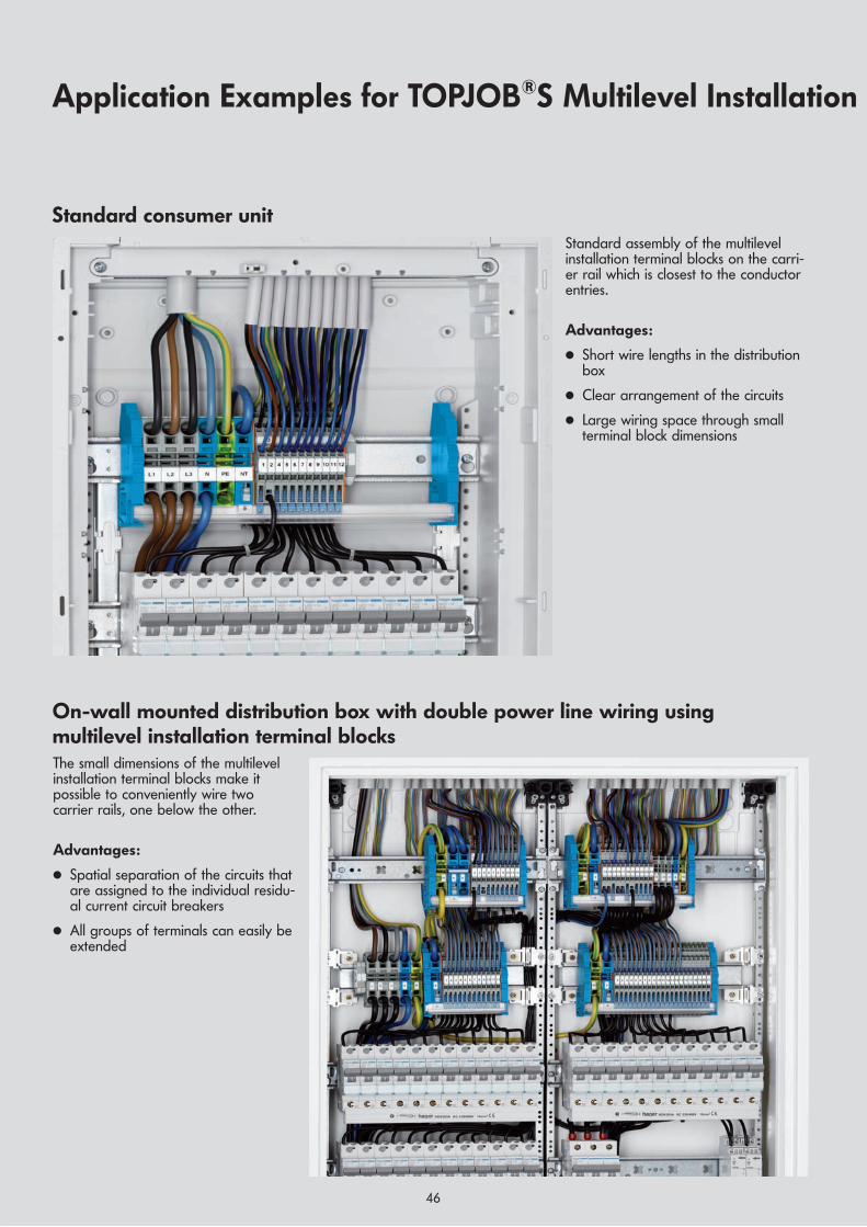
,
46
Standard consumer unit
Application Examples for TOPJOB®S Multilevel Installation
Standard assembly of the multilevelinstallation terminal blocks on the carri-er rail which is closest to the conductorentries.
Advantages:
● Short wire lengths in the distributionbox
● Clear arrangement of the circuits
● Large wiring space through smallterminal block dimensions
The small dimensions of the multilevelinstallation terminal blocks make itpossible to conveniently wire twocarrier rails, one below the other.
Advantages:
● Spatial separation of the circuits thatare assigned to the individual residu-al current circuit breakers
● All groups of terminals can easily beextended
On-wall mounted distribution box with double power line wiring usingmultilevel installation terminal blocks

,
47
On-wall mounted distribution box for power linesand building automation components
Separate arrangement of automationcomponents and installation devices.
Advantages:
● Visual separation of power devices andelectronics allows easy assignment offunctions and error checking
● Optimal utilization of the bus control-lers through a long, vertically moun-ted carrier rail
Terminal Blocks in Standard Distribution Boxes

4848
Commoning sockets/lighting fixtures Parts list2 x 249-117 End stop 10 mm8 x 2003-7646 Multilevel installation terminal
block N/L/PE2 x 2002-477 Staggered jumper 7-way1 x 2002-408 Push-in type jumper bar 8-way1 x 2009-110 Marker strips1 x 793-5566 WMB
Commoning three-phase circuits Parts list2 x 2009-305 Busbar carrier with end stop
function1 x 2016-1207 2-conductor earth conductor
terminal block1 x 2016-7114 Single conductor N-
disconnect terminal block1 x 2003-7641 Multilevel installation terminal
block NT/L/PE4 x 2003-7642 Multilevel installation terminal
block L/L3 x 2003-7646 Multilevel installation terminal
block N/L/PE4 x 2002-477 Staggered jumper 7-way1 x 2009-110 Marker strips1 x 793-5566 WMB
TOPJOB®SExamples of Circuit Configuration with Staggered Jumpers

4949
ApprovalsDated April 2006
A list of approvals (update: catalog deadline) is provided on this page. Due to the numerous agencies and approvals as well as the ever-increasing number of new products, our online catalog provides you with complete up-to-date information at www.wago.com
Item Approval- Vol- Cur- CrossNo. No. tage rent Section
V A AWG/mm2
Item Approval- Vol- Cur- CrossNo. No. tage rent Section
V A AWG/mm2
Item Approval- Vol- Cur- CrossNo. No. tage rent Section
V A AWG/mm2
Item Approval- Vol- Cur- CrossNo. No. tage rent Section
V A AWG/mm2
UL – U Underwriters Laboratories
USA2001-120 . E45172 600 15 22-142001-1207 E45172 22-142001-130 . E45172 600 15 22-142001-1307 E45172 22-142001-140. E45172 600 15 22-142001-1407 E45172 22-142002-120 . E45172 600 20 22-122002-1207 E45172 22-122002-130 . E45172 600 20 22-122002-1307 E45172 22-122002-140. E45172 600 20 22-122002-1407 E45172 22-122002-22 . . E45172 300/600 20/5 22-122002-32 . . E45172 300/600 20/5 22-122004-120 . E45172 600 30 20-102004-1207 E45172 20-102004-130 . E45172 600 30 20-102004-1307 E45172 20-102004-140. E45172 600 30 20-102004-1407 E45172 20-102006-120 . E45172 600 50 20-82006-1207 E45172 20-82006-130 . E45172 600 50 20-82006-1307 E45172 20-82016-120 . E45172 600 85 20-42016-1207 E45172 20-42016-130 . E45172 600 85 20-42016-1307 E45172 20-4
K N.V. tot Keuring van Elektro- technische Materialien, Netherlands
2001-120 . NL2031569.05 800 18 0,5-2,52001-1207 NL2031569.05 0,5-2,52001-130 . NL2031569.05 800 18 0,5-2,52001-1307 NL2031569.05 0,5-2,52001-140 . NL2031569.05 800 18 0,5-2,52001-1407 NL2031569.05 0,5-2,52002-120 . NL2086303.01 800 24 0,5-42002-1207 NL2086303.01 0,5-42002-130 . NL2086303.01 800 24 0,5-42002-1307 NL2086303.01 0,5-42002-140 . NL2086303.01 800 24 0,5-42002-1407 NL2086303.01 0,5-42002-22 . . NL2086303.01 500 24 0,2-42002-32 . . NL2086303.01 500 24 0,2-42003-7641 NL2079570.51 250/400 32 0,25-42003-7642 NL2079570.51 400 32 0,25-42003-7645 NL2079570.51 250/400 32 0,25-42003-7646 NL2079570.51 250/400 32 0,25-42003-7649 NL2079570.51 400 32 0,25-42004-120 . NL2031569.08 800 32 0,5-62004-1207 NL2031569.08 0,5-62004-130 . NL2031569.08 800 32 0,5-62004-1307 NL2031569.08 0,5-62004-140 . NL2031569.08 800 32 0,5-62004-1407 NL2031569.08 0,5-62006-120 . NL2031569.03 800 41 0,5-102006-1207 NL2031569.03 0,5-102006-130 . NL2031569.03 800 41 0,5-102006-1307 NL2031569.03 0,5-102010-120 . NL2031569.02 800 57 0,5-162010-1207 NL2031569.02 0,5-162010-130 . NL2031569.02 800 57 0,5-162010-1307 NL2031569.02 0,5-162016-120 . NL2031569.04 800 76 0,5-25 “f“2016-1207 NL2031569.04 0,5-25 “f“2016-130 . NL2031569.04 800 76 0,5-25 “f“2016-1307 NL2031569.04 0,5-25 “f“
CSA – Canadian Standard 2 Association
Canada2001-120 . 154112-1645434 600 15 22-142001-1207 154112-1645434 22-142001-130 . 154112-1645434 600 15 22-142001-1307 154112-1645434 22-142001-140 . 154112-1645434 600 15 22-142001-1407 154112-1645434 22-142002-120 . 154112-1536069 600 20 22-122002-1207 154112-1536069 22-122002-130 . 154112-1536069 600 20 22-122002-1307 154112-1536069 22-122002-140 . 154112-1536069 600 20 22-122002-1407 154112-1536069 22-122004-120 . 154112-1645435 600 30 20-102004-1207 154112-1645435 20-102004-130 . 154112-1645435 600 30 20-102004-1307 154112-1645435 20-102004-140 . 154112-1645435 600 30 20-102004-1407 154112-1645435 20-102006-120 . 154112-1543858 600 50 20-82006-1207 154112-1543858 20-82006-130 . 154112-1543858 600 50 20-82006-1307 154112-1543858 20-82010-120 . 154112-1645436 600 65 20-6
2010-1207 154112-1645436 20-62010-130 . 154112-1645436 600 65 20-62010-1307 154112-1645436 20-62016-120 . 154112-1579112 600 85 20-42016-1207 154112-1579112 20-42016-130 . 154112-1579112 600 85 20-42016-1307 154112-1579112 20-4
LR –
0 Lloyd’s Register of ShippingGreat Britain
2002-120 . 91/20112(E3) 800 24 0,5-42002-1207 91/20112(E3) 0,5-42002-130 . 91/20112(E3) 800 24 0,5-42002-1307 91/20112(E3) 0,5-42002-140 . 91/20112(E3) 800 24 0,5-42002-1407 91/20112(E3) 0,5-42006-120 . 91/20112(E3) 800 41 0,5-102006-1207 91/20112(E3) 0,5-102006-130 . 91/20112(E3) 800 41 0,5-102006-1307 91/20112(E3) 0,5-102016-120 . 91/20112(E3) 800 76 0,5-25 “f“2016-1207 91/20112(E3) 0,5-25 “f“2016-130 . 91/20112(E3) 800 76 0,5-25 “f“2016-1307 91/20112(E3) 0,5-25 “f“
GL – Germanischer Lloydg Germany2002-120 . 91/20112(E3) 800 24 0,5-42002-1207 91/20112(E3) 0,5-42002-130 . 91/20112(E3) 800 24 0,5-42002-1307 91/20112(E3) 0,5-42002-140 . 91/20112(E3) 800 24 0,5-42002-1407 91/20112(E3) 0,5-42006-120 . 91/20112(E3) 800 41 0,5-102006-1207 91/20112(E3) 0,5-102006-130 . 91/20112(E3) 800 41 0,5-102006-1307 91/20112(E3) 0,5-102016-120 . 91/20112(E3) 800 76 0,5-25 “f“2016-1207 91/20112(E3) 0,5-25 “f“2016-130 . 91/20112(E3) 800 76 0,5-25 “f“2016-1307 91/20112(E3) 0,5-25 “f“
DNV – Det Norske Veritas Denmark
2002-120 . E7570 800 24 0,5-42002-1207 E7570 0,5-42002-130 . E7570 800 24 0,5-42002-1307 E7570 0,5-42002-140 . E7570 800 24 0,5-42002-1407 E7570 0,5-42006-120 . E7570 800 41 0,5-102006-1207 E7570 0,5-102006-130 . E7570 800 41 0,5-102006-1307 E7570 0,5-162016-120 . E7570 800 76 0,5-25 “f“2016-1207 E7570 0,5-25 “f“2016-130 . E7570 800 76 0,5-25 “f“2016-1307 E7570 0,5-25 “f“
ABS – American BureauABS of ShippingUSA
2001-120 . 05-HG476175/1-PDA 800 18 0,5-2,52001-1207 05-HG476175/1-PDA 0,5-2,52001-130 . 05-HG476175/1-PDA 800 18 0,5-2,52001-1307 05-HG476175/1-PDA 0,5-2,52001-140 . 05-HG476175/1-PDA 800 18 0,5-2,52001-1407 05-HG476175/1-PDA 0,5-2,52002-120 . 05-HG476175/1-PDA 800 24 0,5-42002-1207 05-HG476175/1-PDA 0,5-42002-130 . 05-HG476175/1-PDA 800 24 0,5-42002-1307 05-HG476175/1-PDA 0,5-42002-140 . 05-HG476175/1-PDA 800 24 0,5-42002-1407 05-HG476175/1-PDA 0,5-42004-120 . 05-HG476175/1-PDA 800 32 0,5-62004-1207 05-HG476175/1-PDA 0,5-62004-130 . 05-HG476175/1-PDA 800 32 0,5-62004-1307 05-HG476175/1-PDA 0,5-62004-140 . 05-HG476175/1-PDA 800 32 0,5-62004-1407 05-HG476175/1-PDA 0,5-62006-120 . 05-HG476175/1-PDA 800 41 0,5-162006-1207 05-HG476175/1-PDA 0,5-162006-130 . 05-HG476175/1-PDA 800 41 0,5-162006-1307 05-HG476175/1-PDA 0,5-162010-120 . 05-HG476175/1-PDA 800 57 0,5-162010-1207 05-HG476175/1-PDA 0,5-162010-130 . 05-HG476175/1-PDA 800 57 0,5-162010-1307 05-HG476175/1-PDA 0,5-162016-120 . 05-HG476175/1-PDA 800 76 0,5-25 “f“2016-1207 05-HG476175/1-PDA 0,5-25 “f“2016-130 . 05-HG476175/1-PDA 800 76 0,5-25 “f“2016-1307 05-HG476175/1-PDA 0,5-25 “f“
CENELEC CERTIFICATION AGREEMENTCCA-NL –
fN.V. tot Keuring van Elektro- technische Materialien, Netherlands
According to the CENELEC CertificationAgreement, the CCA certificate is recognized in thefollowing European countries:Belgium, Denmark, Germany, Greece, Spain,France, Ireland, Italy, Luxembourg, Netherlands,Austria, Portugal, Finland, Sweden, Great Britain,Czech Republic, Estonia, Cyprus, Latvia, Lithuania,Hungary, Malta, Poland, Slovenia, Slovakia2001-130 . NL5724 800 18 0,5-2,52001-1307 NL5724 0,5-2,52001-140 . NL5724 800 18 0,5-2,52001-1407 NL5724 0,5-2,52002-120 . NL5851 800 24 0,2-42002-1207 NL5851 0,2-42002-130 . NL5851 800 24 0,2-42002-1307 NL5851 0,2-42002-140 . NL5851 800 24 0,2-42002-1407 NL5851 0,2-42002-22 . . NL5851 500 24 0,2-42002-32 . . NL5851 500 24 0,2-42003-7641 NL5828 250/400 32 0,25-42003-7642 NL5828 400 32 0,25-42003-7645 NL5828 250/400 32 0,25-42003-7646 NL5828 250/400 32 0,25-42003-7649 NL5828 0,25-42004-120 . NL5725 800 32 0,5-62004-1207 NL5725 0,5-62004-130 . NL5725 800 32 0,5-62004-1307 NL5725 0,5-62004-140 . NL5725 800 32 0,5-62004-1407 NL5725 0,5-62006-120 . NL5551 800 41 0,5-102006-1207 NL5551 0,5-102006-130 . NL5551 800 41 0,5-102006-1307 NL5551 0,5-102010-120 . NL5755 800 57 0,5-162010-1207 NL5755 0,5-162010-130 . NL5755 800 57 0,5-162010-1307 NL5755 0,5-162016-120 . NL5555 800 76 0,5-25 “f“2016-1207 NL5555 0,5-25 “f“2016-130 . NL5555 800 76 0,5-25 “f“2016-1307 NL5555 0,5-25 “f“
PTB Physikalisch Technische
P BundesanstaltGermanyEEx e II
2001-120 . PTB05Atex1094U 550 16 0,5-2,5with push-in type jumper bar max 17 A
2001-120 . IECExPTB05.0034U 550 16 0,5-2,5with push-in type jumper bar max 17 A
2001-1207 PTB05Atex1094U 0,5-2,52001-1207 IECExPTB05.0034U 0,5-2,52001-130 . PTB05Atex1094U 550 16 0,5-2,5
with push-in type jumper bar 17 A2001-130 . IECEx
PTB05.0034U 550 16 0,5-2,5with push-in type jumper bar 17 A
2001-1307 PTB05Atex1094U 0,5-2,52001-1307 IECExPTB05.0034U 0,5-2,52001-140 . PTB05Atex1094U 550 16 0,5-2,5
with push-in type jumper bar 17 A2001-140 . IECEx
PTB05.0034U 550 16 0,5-2,5with push-in type jumper bar 17 A
2001-1407 PTB05Atex1094U 0,5-2,52001-1407 IECExPTB03.0004U 0,5-2,5
2002-120 . PTB03Atex1162U 550 22 0,2-4with push-in type jumper bar 20 A
2002-120 . IECExPTB03.0004U 550 22 0,2-4with push-in type jumper bar 20 A
2002-1207 PTB03Atex1162U 0,2-42002-1207 IECExPTB03.0004U 0,2-42002-130 . PTB03Atex1162U 550 22 0,2-4
with push-in type jumper bar 20 A2002-130 . IECEx
PTB03.0004U 550 22 0,2-4with push-in type jumper bar 20 A
2002-1307 PTB03Atex1162U 0,2-42002-1307 IECExPTB03.0004U 0,2-42002-140 . PTB03Atex1162U 550 22 0,2-4
with push-in type jumper bar 20 A2002-140 . IECEx
PTB03.0004U 550 22 0,2-4with push-in type jumper bar 20 A
2002-1407 PTB03Atex1162U 0,2-42002-1407 IECExPTB03.0004U 0,2-4
2004-120 . PTB05Atex1095U 550 30 0,5-6with push-in type jumper bar 30 A
2004-120 . IECExPTB05.0033U 550 30 0,5-6with push-in type jumper bar max 30 A
2004-1207 PTB05Atex1095U 0,5-62004-1207 IECExPTB05.0033U 0,5-62004-130 . PTB05Atex1095U 550 30 0,5-6
with push-in type jumper bar max 30A2004-130 . IECEx
PTB05.0033U 550 30 0,5-6with push-in type jumper bar max 30 A
2004-1307 PTB05Atex1095U 0,5-62004-1307 IECExPTB05.0033U 0,5-62004-140 . PTB05Atex1095U 550 30 0,5-6
with push-in type jumper bar max 30 A2004-140 . IECEx
PTB05.0033U 550 30 0,5-6with push-in type jumper bar max 30 A
2004-1407 PTB05Atex1095U 0,5-62004-1407 IECExPTB05.0033U 0,5-6
2006-120 . PTB05Atex1030U 550 33 0,5-10with push-in type jumper bar max 38 A
2006-120 . IECExPTB05.0014U 550 33 0,5-10with push-in type jumper bar max 38 A
2006-1207 PTB05Atex1030U 0,5-102006-1207 IECExPTB05.0014U 0,5-102006-130 . PTB05Atex1030U 550 33 0,5-10
with push-in type jumper bar max 36 A2006-130 . IECEx
PTB05.0014U 550 33 0,5-10with push-in type jumper bar max 36 A
2006-1307 PTB05Atex1030U 0,5-102006-1307 IECExPTB05.0014U 0,5-10
2010-120 . PTB05Atex1070U 550 51 0,5-16with push-in type jumper bar max 51 A
2010-120 . IECExPTB06.0003U 550 51 0,5-16with push-in type jumper bar max 51 A
2010-1207 PTB05Atex1070U 0,5-162010-1207 IECExPTB06.0003U 0,5-162010-130 . PTB05Atex1070U 550 50 0,5-16
with push-in type jumper bar max 50 A2010-130 . IECEx
PTB06.0003U 550 50 0,5-16with push-in type jumper bar max 50 A
2010-1307 PTB05Atex1070U 0,5-162010-1307 IECExPTB06.0003U 0,5-16
2016-120 . PTB05Atex1031U 550 33 0,5-25with push-in type jumper bar max 70 A
2016-120 . IECExPTB05.0015U 550 33 0,5-25with push-in type jumper bar max 70 A
2016-1207 PTB05Atex1031U 0,5-252016-1207 IECExPTB05.0015U 0,5-252016-130 . PTB05Atex1031U 550 33 0,5-25
with push-in type jumper bar max 67 A2016-130 . IECEx
PTB05.0015U 550 33 0,5-25with push-in type jumper bar max 67 A
2016-1307 PTB05Atex1031U 0,5-252016-1307 IECExPTB05.0015U 0,5-25
c URus – Y Underwriters Laboratories
USA2001-120 . E185892 550 15 22-142001-1207 E185892 22-142001-130 . E185892 550 15 22-142001-1307 E185892 22-142001-140 . E185892 550 15 22-142001-1407 E185892 22-142002-120 . E185892 550 20 22-122002-1207 E185892 22-122002-130 . E185892 550 20 22-122002-1307 E185892 22-122002-140 . E185892 550 20 22-122002-1407 E185892 22-122004-120 . E185892 550 30 20-102004-1207 E185892 20-102004-130 . E185892 550 30 20-102004-1307 E185892 20-102004-140 . E185892 550 30 20-102004-1407 E185892 20-102006-120 . E185892 550 50 20-82006-1207 E185892 20-82006-130 . E185892 550 50 20-82006-1307 E185892 20-82016-120 . E185892 550 85 20-42016-1207 E185892 20-42016-130 . E185892 550 85 20-42016-1307 E185892 20-4

50
Index of Item Nos.
Item No. Page
Series 206206-204 42206-216 42
Series 209209-105 28209-113 41209-114 41
Series 210210-110 39210-112 41210-113 41210-133 28210-136 24210-136 25210-136 28210-136 31210-136 32210-136 33210-137 24210-137 25
210-281 28
210-345 41
210-619 41210-620 41210-621 41210-622 41
210-400/2000-0001 41210-400/2000-0002 41
Series 216216-100 42
216-208 42216-241 42216-242 42216-243 42216-244 42216-246 42216-262 42216-263 42216-264 42216-266 42216-267 42216-284 42216-286 42216-287 42216-288 42216-289 42
Series 248248-... 25
Series 249249-... 25
249-116 41249-117 41
Series 258258-298 40
Series 734734-326 24734-326 25734-327 24734-327 25734-328 24734-328 25734-329 24734-329 25
Series 777777-303 28
Series 793793-1604 39
793-4... 24793-4... 25793-4... 25793-4472 38793-4501 39793-4502 38793-4503 38793-4504 38793-4505 38793-4506 38793-4507 38793-4508 38793-4509 38793-4510 38793-4511 38793-4512 38793-4513 38793-4514 38793-4515 38793-4516 38793-4517 38793-4544 38793-4545 38793-4565 38793-4566/000-06 39793-4602 39793-4603 39793-4605 39793-4606 39793-4607 39793-4608 39793-4609 39793-4610 39793-4611 39793-4612 39793-4613 39793-4614 39793-4615 39793-4616 39793-4617 39793-4644 39793-4645 39793-4665 39793-4666 39793-4667 39793-4668 39
793-5... 24793-5... 25793-5472 38793-5501 39793-5502 38793-5503 38793-5504 38793-5505 38793-5506 38793-5507 38793-5508 38793-5509 38793-5510 38793-5511 38793-5512 38793-5513 38793-5514 38793-5515 38793-5516 38793-5517 38793-5544 38793-5545 38793-5565 38793-5566/000-23 39793-5599 38793-5602 39793-5603 39793-5604 39793-5605 39
793-5606 39793-5607 39793-5608 39793-5609 39793-5610 39793-5611 39793-5612 39793-5613 39793-5614 39793-5615 39793-5616 39793-5617 39793-5644 39793-5645 39793-5665 39793-5666 39793-5667 39793-5668 39793-5699 39793-5900 39
Series 794794-4... 24794-4601 39794-4602 39794-4603 39794-4604 39794-4605 39794-4657 39794-4672 39
794-5... 24794-5... 25794-5557 38794-5558 38794-5601 39794-5602 39794-5603 39794-5604 39794-5605 39794-5658 39794-5672 39
Series 20012001-171 16
2001-402 162001-403 162001-404 162001-405 162001-405 342001-410 162001-433 162001-434 162001-435 162001-440 16
2001-511 162001-511 242001-549 162001-549 242001-552 252001-553 252001-554 252001-555 252001-556 252001-557 252001-558 252001-559 252001-560 25
2001-1201 162001-1201 182001-1202 162001-1204 162001-1207 162001-1301 162001-1302 162001-1304 162001-1307 162001-1401 16
2001-1402 162001-1404 162001-1407 16
Series 20022002-115 172002-115 222002-115 272002-115 312002-115 332002-121 262002-121 312002-121 322002-121 342002-121 352002-131 272002-131 362002-131 372002-171 172002-171 222002-171 312002-171 322002-171 332002-172 172002-172 222002-172 312002-172 322002-172 33
2002-402 172002-402 222002-402 262002-402 272002-402 282002-402 312002-402 322002-402 332002-402 342002-402 352002-402 362002-402 372002-403 172002-403 222002-403 262002-403 272002-403 282002-403 312002-403 322002-403 332002-403 342002-403 352002-403 362002-403 372002-404 172002-404 222002-404 262002-404 272002-404 282002-404 312002-404 322002-404 332002-404 342002-404 352002-404 362002-404 372002-405 172002-405 222002-405 262002-405 272002-405 282002-405 312002-405 322002-405 332002-405 342002-405 352002-405 362002-405 372002-410 172002-410 262002-410 272002-410 282002-410 31
2002-410 322002-410 332002-410 342002-410 342002-410 352002-410 362002-410 372002-433 172002-433 222002-433 262002-433 272002-433 282002-433 312002-433 322002-433 332002-433 342002-433 342002-433 352002-433 362002-433 372002-434 172002-434 222002-434 272002-434 282002-434 312002-434 322002-434 332002-434 342002-434 352002-434 362002-434 372002-435 172002-435 222002-435 262002-435 272002-435 282002-435 312002-435 322002-435 332002-435 342002-435 352002-435 362002-435 372002-440 172002-440 222002-440 262002-440 272002-440 282002-440 312002-440 322002-440 332002-440 342002-440 352002-440 362002-440 372002-472 282002-472 312002-472 322002-472 332002-473 282002-473 312002-473 322002-473 332002-474 282002-474 312002-474 322002-474 332002-475 282002-475 312002-475 322002-475 332002-482 282002-482 312002-482 322002-482 33
2002-511 172002-511 222002-511 242002-511 312002-511 322002-511 332002-541 24
Item No. Page Item No. Page Item No. Page Item No. Page

51
2002-549 172002-549 222002-549 312002-549 322002-552 252002-553 252002-554 252002-555 252002-556 252002-557 252002-558 252002-559 252002-560 25
2002-1201 172002-1202 172002-1204 172002-1207 172002-1291 162002-1291 172002-1292 162002-1292 172002-1301 172002-1302 172002-1304 172002-1307 172002-1391 162002-1391 172002-1392 162002-1491 162002-1492 162002-1601 312002-1602 312002-1604 312002-1671 312002-1672 312002-1674 312002-1691 312002-1692 172002-1692 312002-1692 312002-1801 322002-1802 322002-1804 322002-1871 322002-1872 322002-1874 322002-1891 322002-1892 32
2002-2201 262002-2202 262002-2203 262002-2204 262002-2207 262002-2208 262002-2209 262002-2211/1000-410 342002-2211/1000-411 342002-2213/1000-487 352002-2213/1000-488 352002-2214/1000-489 352002-2214/1000-490 352002-2214/1000-491 342002-2214/1000-492 342002-2217 262002-2221/1000-413 352002-2221/1000-434 352002-2227 262002-22292 352002-2231 262002-2232 262002-2233 262002-2234 262002-2237 262002-2238 262002-2239 262002-2247 262002-2257 262002-2291 262002-2291 342002-2291 352002-2292 26
2002-2292 342002-2292 352002-2951 332002-2952 332002-2954 332002-2958 332002-2959 332002-2971 332002-2972 332002-2974 332002-2991 332002-2992 33
2002-3201 272002-3203 272002-3204 272002-3207 272002-3208 272002-3209 272002-3211/1000-410 362002-3211/1000-411 362002-3211/1000-675 362002-3211/1000-676 362002-3212/1000-673 372002-3212/1000-674 372002-3217 272002-3218 272002-3221/1000-413 372002-3221/1000-434 372002-3227 272002-3228 272002-3231 272002-3233 272002-3234 272002-3237 272002-3238 272002-3239 272002-3247 272002-3248 272002-3257 272002-3258 272002-3291 272002-3291 362002-3291 372002-3292 272002-3292 362002-3292 37
2002-434 26
2002-6301 222002-6302 222002-6304 222002-6307 222002-6391 222002-6392 222002-6401 222002-6402 222002-6404 222002-6407 22
2002-7111 302002-7114 302002-7192 30
Series 20032003-7641 282003-7642 282003-7645 282003-7646 282003-7649 282003-7692 28
Series 20042004-115 182004-171 182004-172 18
2004-402 182004-403 182004-404 18
2004-405 182004-410 182004-433 182004-434 182004-435 182004-440 18
2004-511 182004-511 242004-541 242004-549 182004-549 242004-552 252004-553 252004-554 252004-555 25
2004-1201 182004-1202 182004-1204 182004-1207 182004-1291 182004-1292 182004-1301 182004-1302 182004-1304 182004-1307 182004-1391 182004-1392 182004-1401 182004-1402 182004-1404 182004-1407 182004-1491 182004-1492 18
Series 20052005-115 32
2005-7641 292005-7642 292005-7645 292005-7646 292005-7649 29
Series 20062006-115 19
2006-402 192006-403 192006-404 192006-405 192006-433 192006-434 192006-435 192006-499 19
2006-549 24
2006-1201 192006-1202 192006-1204 192006-1207 192006-1291 192006-1292 192006-1301 192006-1302 192006-1304 192006-1307 192006-1391 192006-1392 192006-7111 302006-7114 302006-7192 30
Series 20092009-110 162009-110 192009-110 202009-110 21
2009-110 242009-110 252009-110 262009-110 272009-110 402009-115 252009-115 382009-115 392009-115 402009-130 162009-130 192009-130 202009-130 212009-130 242009-130 252009-130 262009-130 272009-130 402009-174 162009-174 172009-174 182009-174 192009-174 212009-174 222009-174 232009-174 282009-174 312009-174 322009-174 332009-182 162009-182 172009-182 182009-182 192009-182 202009-182 212009-182 222009-182 232009-182 282009-182 312009-182 322009-182 332009-191 412009-192 412009-193 412009-196 41
2009-304 282009-305 28
2009-412 232009-414 232009-416 23
Series 20102010-100 202010-174 20
2010-402 202010-403 202010-404 202010-405 202010-433 202010-434 202010-435 20
2010-1201 202010-1202 202010-1204 202010-1207 202010-1291 202010-1292 202010-1301 202010-1302 202010-1304 202010-1307 202010-1391 202010-1392 20
Series 20162016-100 212016-115 21
2016-402 212016-403 212016-404 212016-405 212016-433 212016-434 212016-435 212016-499 202016-499 21
2016-1201 212016-1202 212016-1204 212016-1207 212016-1207 282016-1291 212016-1292 212016-1301 212016-1302 212016-1304 212016-1307 212016-1391 212016-1392 21
2016-7111 302016-7114 282016-7114 302016-7192 30
Series ....../000-02 39.../000-05 39.../000-06 39.../000-07 39.../000-12 39.../000-17 39.../000-23 39.../000-24 39
Item No. Page Item No. Page Item No. Page Item No. Page Item No. Page

5117
9940
· 08
88-0
164/
0200
-360
1 · T
OPJ
OB®
S 2.
0 · E
· 10
/06
· JA
610
49 ·
Prin
ted
in G
erm
any
· Sub
ject
to d
esig
n ch
ange
s4
04
54
54
37
62
91
WAGO Kontakttechnik GmbH & Co. KGP.O. Box 28 80 · 32385 MindenHansastraße 27 · 32423 MindenGermanyPhone +49 5 71/8 87-0Fax +49 5 71/8 [email protected]