Terminal Blocks BNH/BN Terminal Blocks - Farnell element14 · Terminal Blocks Circuit Breakers...
11
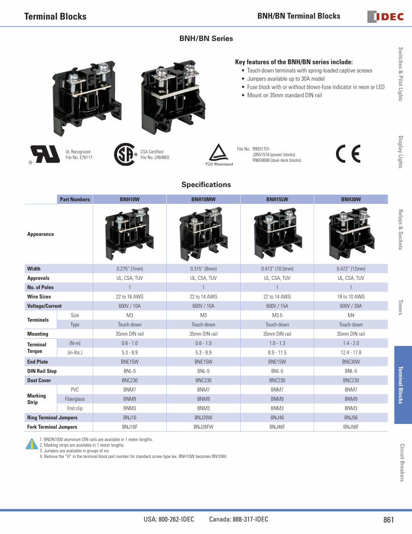
Switches & Pilot Lights Display Lights Relays & Sockets Timers Terminal Blocks Circuit Breakers Terminal Blocks BNH/BN Terminal Blocks 861 USA: 800-262-IDEC Canada: 888-317-IDEC BNH/BN Series Key features of the BNH/BN series include: Touch-down terminals with spring-loaded captive screws Jumpers available up to 30A model Fuse block with or without blown-fuse indicator in neon or LED Mount on 35mm standard DIN rail • • • • UL Recognized File No. E78117 CSA Certified File No. LR64803 File No. R9551701 J9551516 (power blocks) R9650688 (dual-deck blocks) Specifications Part Numbers BNH10W BNH15MW BNH15LW BNH30W Appearance Width 0.275” (7mm) 0.315” (8mm) 0.413” (10.5mm) 0.472” (12mm) Approvals UL, CSA, TUV UL, CSA, TUV UL, CSA, TUV UL, CSA, TUV No. of Poles 1 1 1 1 Wire Sizes 22 to 16 AWG 22 to 14 AWG 22 to 14 AWG 18 to 10 AWG Voltage/Current 600V / 10A 600V / 10A 600V / 15A 600V / 30A Terminals Size M3 M3 M3.5 M4 Type Touch-down Touch-down Touch-down Touch-down Mounting 35mm DIN rail 35mm DIN rail 35mm DIN rail 35mm DIN rail Terminal Torque (N-m) 0.6 - 1.0 0.6 - 1.0 1.0 - 1.3 1.4 - 2.0 (in-lbs.) 5.3 - 8.9 5.3 - 8.9 8.9 - 11.5 12.4 - 17.8 End Plate BNE15W BNE15W BNE15W BNE30W DIN Rail Stop BNL-5 BNL-5 BNL-5 BNL-5 Dust Cover BNC230 BNC230 BNC230 BNC230 Marking Strip PVC BNM7 BNM7 BNM7 BNM7 Fiberglass BNM9 BNM9 BNM9 BNM9 End clip BNM3 BNM3 BNM3 BNM3 Ring Terminal Jumpers BNJ16 BNJ26W BNJ46 BNJ56 Fork Terminal Jumpers BNJ16F BNJ26FW BNJ46F BNJ56F 1. BNDN1000 aluminum DIN rails are available in 1 meter lengths. 2. Marking strips are available in 1 meter lengths. 3. Jumpers are available in groups of six. 4. Remove the “H” in the terminal block part number for standard screw type (ex. BNH10W becomes BN10W).
Transcript of Terminal Blocks BNH/BN Terminal Blocks - Farnell element14 · Terminal Blocks Circuit Breakers...
Sw
itches & P
ilot LightsD
isplay LightsR
elays & S
ocketsTim
ersTerm
inal Blocks
Circuit B
reakers
Terminal Blocks BNH/BN Terminal Blocks
861USA: 800-262-IDEC Canada: 888-317-IDEC
BNH/BN Series
Key features of the BNH/BN series include:Touch-down terminals with spring-loaded captive screws
Jumpers available up to 30A model
Fuse block with or without blown-fuse indicator in neon or LED
Mount on 35mm standard DIN rail
•
•
•
•
UL RecognizedFile No. E78117
CSA Certifi edFile No. LR64803
File No. R9551701 J9551516 (power blocks) R9650688 (dual-deck blocks)
Specifi cations
Part Numbers BNH10W BNH15MW BNH15LW BNH30W
Appearance
Width 0.275” (7mm) 0.315” (8mm) 0.413” (10.5mm) 0.472” (12mm)
Approvals UL, CSA, TUV UL, CSA, TUV UL, CSA, TUV UL, CSA, TUV
No. of Poles 1 1 1 1
Wire Sizes 22 to 16 AWG 22 to 14 AWG 22 to 14 AWG 18 to 10 AWG
Voltage/Current 600V / 10A 600V / 10A 600V / 15A 600V / 30A
TerminalsSize M3 M3 M3.5 M4
Type Touch-down Touch-down Touch-down Touch-down
Mounting 35mm DIN rail 35mm DIN rail 35mm DIN rail 35mm DIN rail
Terminal Torque
(N-m) 0.6 - 1.0 0.6 - 1.0 1.0 - 1.3 1.4 - 2.0
(in-lbs.) 5.3 - 8.9 5.3 - 8.9 8.9 - 11.5 12.4 - 17.8
End Plate BNE15W BNE15W BNE15W BNE30W
DIN Rail Stop BNL-5 BNL-5 BNL-5 BNL-5
Dust Cover BNC230 BNC230 BNC230 BNC230
Marking Strip
PVC BNM7 BNM7 BNM7 BNM7
Fiberglass BNM9 BNM9 BNM9 BNM9
End clip BNM3 BNM3 BNM3 BNM3
Ring Terminal Jumpers BNJ16 BNJ26W BNJ46 BNJ56
Fork Terminal Jumpers BNJ16F BNJ26FW BNJ46F BNJ56F
1. BNDN1000 aluminum DIN rails are available in 1 meter lengths.2. Marking strips are available in 1 meter lengths.3. Jumpers are available in groups of six.4. Remove the “H” in the terminal block part number for standard screw type (ex. BNH10W becomes BN10W).
Sw
itch
es &
Pil
ot L
ight
sR
elay
s &
Soc
kets
Tim
ers
Term
inal
Blo
cks
Cir
cuit
Bre
aker
sBNH/BN Terminal Blocks
862 www.idec.com
Sw
itch
es &
Pil
ot L
ight
sD
ispl
ay L
ight
sR
elay
s &
Soc
kets
Tim
ers
Term
inal
Blo
cks
Cir
cuit
Bre
aker
s
Terminal Blocks
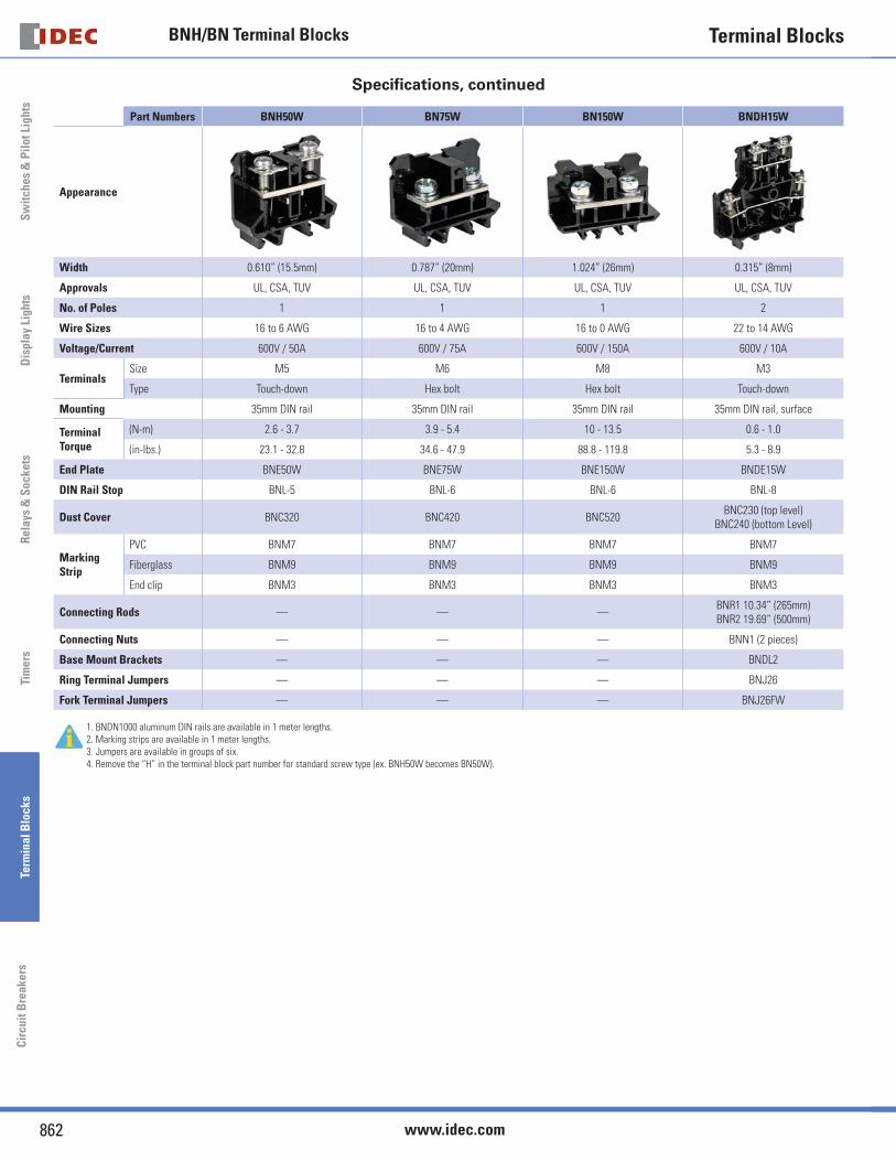
Specifi cations, continued
Part Numbers BNH50W BN75W BN150W BNDH15W
Appearance
Width 0.610” (15.5mm) 0.787” (20mm) 1.024” (26mm) 0.315” (8mm)
Approvals UL, CSA, TUV UL, CSA, TUV UL, CSA, TUV UL, CSA, TUV
No. of Poles 1 1 1 2
Wire Sizes 16 to 6 AWG 16 to 4 AWG 16 to 0 AWG 22 to 14 AWG
Voltage/Current 600V / 50A 600V / 75A 600V / 150A 600V / 10A
TerminalsSize M5 M6 M8 M3
Type Touch-down Hex bolt Hex bolt Touch-down
Mounting 35mm DIN rail 35mm DIN rail 35mm DIN rail 35mm DIN rail, surface
Terminal Torque
(N-m) 2.6 - 3.7 3.9 - 5.4 10 - 13.5 0.6 - 1.0
(in-lbs.) 23.1 - 32.8 34.6 - 47.9 88.8 - 119.8 5.3 - 8.9
End Plate BNE50W BNE75W BNE150W BNDE15W
DIN Rail Stop BNL-5 BNL-6 BNL-6 BNL-8
Dust Cover BNC320 BNC420 BNC520BNC230 (top level)
BNC240 (bottom Level)
Marking Strip
PVC BNM7 BNM7 BNM7 BNM7
Fiberglass BNM9 BNM9 BNM9 BNM9
End clip BNM3 BNM3 BNM3 BNM3
Connecting Rods — — —BNR1 10.34” (265mm)BNR2 19.69” (500mm)
Connecting Nuts — — — BNN1 (2 pieces)
Base Mount Brackets — — — BNDL2
Ring Terminal Jumpers — — — BNJ26
Fork Terminal Jumpers — — — BNJ26FW
1. BNDN1000 aluminum DIN rails are available in 1 meter lengths.2. Marking strips are available in 1 meter lengths.3. Jumpers are available in groups of six.4. Remove the “H” in the terminal block part number for standard screw type (ex. BNH50W becomes BN50W).
Sw
itches & P
ilot LightsD
isplay LightsR
elays & S
ocketsTim
ersTerm
inal Blocks
Circuit B
reakers
Terminal Blocks BNF Fuse Blocks
863USA: 800-262-IDEC Canada: 888-317-IDEC
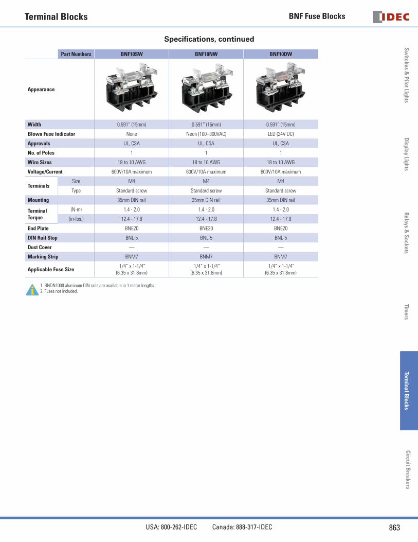
Specifi cations, continued
Part Numbers BNF10SW BNF10NW BNF10DW
Appearance
Width 0.591” (15mm) 0.591” (15mm) 0.591” (15mm)
Blown Fuse Indicator None Neon (100–300VAC) LED (24V DC)
Approvals UL, CSA UL, CSA UL, CSA
No. of Poles 1 1 1
Wire Sizes 18 to 10 AWG 18 to 10 AWG 18 to 10 AWG
Voltage/Current 600V/10A maximum 600V/10A maximum 600V/10A maximum
TerminalsSize M4 M4 M4
Type Standard screw Standard screw Standard screw
Mounting 35mm DIN rail 35mm DIN rail 35mm DIN rail
Terminal Torque
(N-m) 1.4 - 2.0 1.4 - 2.0 1.4 - 2.0
(in-lbs.) 12.4 - 17.8 12.4 - 17.8 12.4 - 17.8
End Plate BNE20 BNE20 BNE20
DIN Rail Stop BNL-5 BNL-5 BNL-5
Dust Cover — — —
Marking Strip BNM7 BNM7 BNM7
Applicable Fuse Size 1/4” x 1-1/4”
(6.35 x 31.8mm) 1/4” x 1-1/4”
(6.35 x 31.8mm) 1/4” x 1-1/4”
(6.35 x 31.8mm)
1. BNDN1000 aluminum DIN rails are available in 1 meter lengths.2. Fuses not included.
Terminal BlocksS
wit
ches
& P
ilot
Lig
hts
Rel
ays
& S
ocke
tsTi
mer
sTe
rmin
al B
lock
sC
ircu
it B
reak
ers
BNF Fuse Blocks
864 www.idec.com
Sw
itch
es &
Pil
ot L
ight
sD
ispl
ay L
ight
sR
elay
s &
Soc
kets
Tim
ers
Term
inal
Blo
cks
Cir
cuit
Bre
aker
s
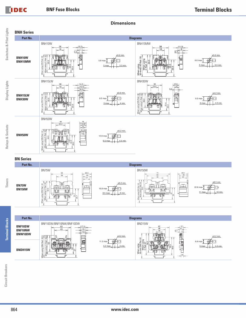
Dimensions
BNH Series
Part No. Diagrams
BNH10WBNH15MW
BNH10W33
.5
29.5
23.5
5.97
10.31838
Whe
n us
ing
DIN
Rai
l: 35
Whe
n us
ing
C R
ail:
41
ø3.2 min.
5 max. 3.3 min.
5.8 max.
BNH15MW
33.5
Whe
n us
ing
C R
ail:
41
Whe
n us
ing
35-m
mD
IN R
ail:
35
29.5
23.5
1838
6.78
11.3
6.6 max.
ø3.2 min.
5 max. 3.3 min.
BNH15LWBNH30W
BNH15LW
33.5
29.5
23.5
1838
8.510.5
14.3
Whe
n us
ing
DIN
Rai
l: 35
Whe
n us
ing
C R
ail:
41
8.5 max.
ø3.6 min.
5 max. 4 min.
BNH30W
31.4
25.4
36.5
19.438
9.612
15.8
Whe
n us
ing
DIN
Rai
l: 38
Whe
n us
ing
C R
ail:
44
9.5 max.
ø4.2 min.
6 max. 4.5 min.
BNH50W
BNH50W
42.5
34.3
28.3
4824.4
1315.518
Whe
n us
ing
DIN
Rai
l: 44
Whe
n us
ing
C R
ail:
50
4.5 min.6.5 max.
12.8 max.
ø5.2 min.
BN Series
Part No. Diagrams
BN75WBN150W
BN75W
42.5
2653
1720
22.5
31.7
25.7
Whe
n us
ing
DIN
Rai
l: 44
Whe
n us
ing
C R
ail:
50
6 min.8.5 max.
ø6.2 min.
16.8 max.
BN150W
50.5
3529
2326
29.8
336374
Whe
n us
ing
DIN
Rai
l: 52
Whe
n us
ing
C R
ail:
50
22.8 max.
ø8.5 min.
11 max. 10 min.
Part No. Diagrams
BNF10SWBNF10NWBNW10DW
BNF10SW/BNF10NW/BNF10DW
4363
1513
3327
17.5
52W
hen
usin
g C
Rai
l: 59
.5
Whe
n us
ing
DIN
Rai
l: 53
.5
5 min.5.2 max.
11.3 max.
ø4.2 min.
BND15W
59.5
Whe
m u
sing
C R
ail:
67
55.5
49.5
183862
8
6.7812
Whe
n us
ing
35-m
m D
IN R
ai: 6
1
6.6 max.
ø3.2 min.
5 max. 3.3 min.
BNDH15W
Terminal BlocksS
wit
ches
& P
ilot
Lig
hts
Rel
ays
& S
ocke
tsTi
mer
sTe
rmin
al B
lock
sC
ircu
it B
reak
ers
Accessories
870 www.idec.com
Sw
itch
es &
Pil
ot L
ight
sD
ispl
ay L
ight
sR
elay
s &
Soc
kets
Tim
ers
Term
inal
Blo
cks
Cir
cuit
Bre
aker
s
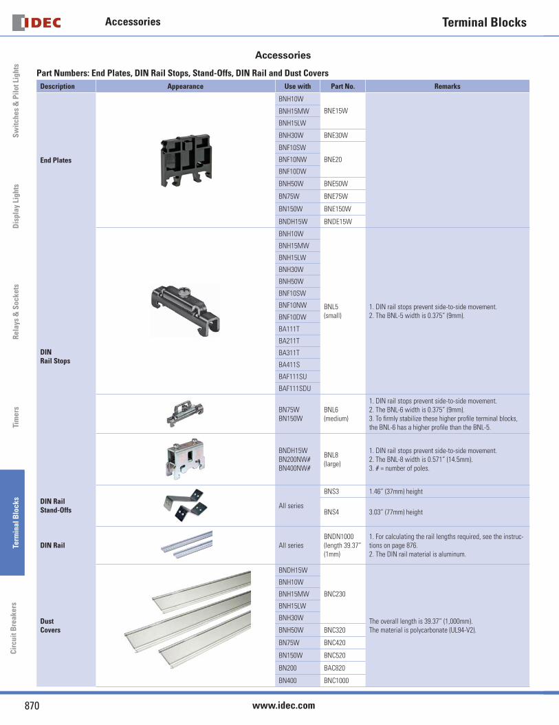
Accessories
Part Numbers: End Plates, DIN Rail Stops, Stand-Offs, DIN Rail and Dust Covers
Description Appearance Use with Part No. Remarks
End Plates
BNH10W
BNE15WBNH15MW
BNH15LW
BNH30W BNE30W
BNF10SW
BNE20BNF10NW
BNF10DW
BNH50W BNE50W
BN75W BNE75W
BN150W BNE150W
BNDH15W BNDE15W
DIN Rail Stops
BNH10W
BNL5(small)
1. DIN rail stops prevent side-to-side movement.2. The BNL-5 width is 0.375” (9mm).
BNH15MW
BNH15LW
BNH30W
BNH50W
BNF10SW
BNF10NW
BNF10DW
BA111T
BA211T
BA311T
BA411S
BAF111SU
BAF111SDU
BN75WBN150W
BNL6(medium)
1. DIN rail stops prevent side-to-side movement.2. The BNL-6 width is 0.375” (9mm).3. To fi rmly stabilize these higher profi le terminal blocks, the BNL-6 has a higher profi le than the BNL-5.
BNDH15WBN200NW#BN400NW#
BNL8(large)
1. DIN rail stops prevent side-to-side movement.2. The BNL-8 width is 0.571” (14.5mm).3. # = number of poles.
DIN Rail Stand-Offs
All series
BNS3 1.46” (37mm) height
BNS4 3.03” (77mm) height
DIN Rail All series BNDN1000 (length 39.37” (1mm)
1. For calculating the rail lengths required, see the instruc-tions on page 876.2. The DIN rail material is aluminum.
Dust Covers
BNDH15W
BNC230
The overall length is 39.37” (1,000mm).The material is polycarbonate (UL94-V2).
BNH10W
BNH15MW
BNH15LW
BNH30W
BNH50W BNC320
BN75W BNC420
BN150W BNC520
BN200 BAC820
BN400 BNC1000
Sw
itches & P
ilot LightsD
isplay LightsR
elays & S
ocketsTim
ersTerm
inal Blocks
Circuit B
reakers
Terminal Blocks Accessories
871USA: 800-262-IDEC Canada: 888-317-IDEC
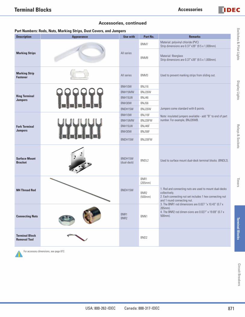
Accessories, continued
Part Numbers: Rods, Nuts, Marking Strips, Dust Covers, and Jumpers
Description Appearance Use with Part No. Remarks
Marking Strips All series
BNM7Material: polyvinyl chloride (PVC) Strip dimensions are 0.37”x39” (9.5 x 1,000mm).
BNM9Material: fi berglass Strip dimensions are 0.37”x39” (9.5 x 1,000mm).
Marking Strip Fastener
All series BNM3 Used to prevent marking strips from sliding out.
Ring Terminal Jumpers
BNH10W BNJ16
Jumpers come standard with 6 points.
Note: insulated jumpers available - add “B” to end of part number. For example, BNJ26WB.
BNH15MW BNJ26W
BNH15LW BNJ46
BNH30W BNJ56
BNDH15W BNJ26W
Fork Terminal Jumpers
BNH10W BNJ16F
BNH15MW BNJ26FW
BNH15LW BNJ46F
BNH30W BNJ56F
BNDH15W BNJ26FW
Surface Mount Bracket
BNDH15W (dual-deck)
BNDL2 Used to surface mount dual-deck terminal blocks. (BNDL2).
M4 Thread Rod BNDH15W
BNR1(265mm)
1. Rod and connecting nuts are used to mount dual-decks collectively.2. Each connecting nut set includes 1 hex connecting nut and 1 round connecting nut.3. The BNR1 rod dimensions are 0.027 “x 10.43” (0.7 x 265mm).4. The BNR2 rod dimen-sions are 0.027” x 19.69” (0.7 x 500mm).
BNR2(500mm)
Connecting NutsBNR1BNR2
BNN1
Terminal Block Removal Tool
BND2
For accessory dimensions, see page 872.
Terminal BlocksS
wit
ches
& P
ilot
Lig
hts
Rel
ays
& S
ocke
tsTi
mer
sTe
rmin
al B
lock
sC
ircu
it B
reak
ers
Accessories
872 www.idec.com
Sw
itch
es &
Pil
ot L
ight
sD
ispl
ay L
ight
sR
elay
s &
Soc
kets
Tim
ers
Term
inal
Blo
cks
Cir
cuit
Bre
aker
s
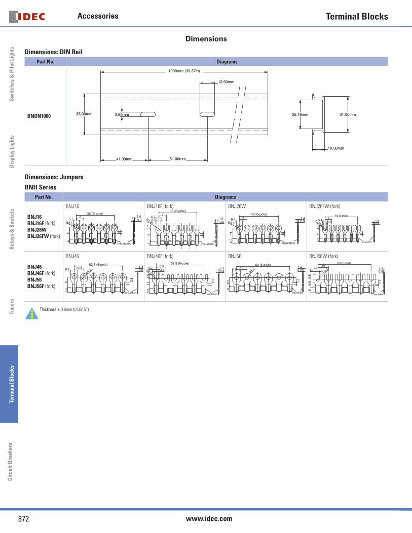
Dimensions
Dimensions: DIN Rail
Part No. Diagrams
BNDN1000 35.00mm
41.00mm 51.00mm
3.80mm
12.50mm
1000mm (39.37in)
31.00mm
10.50mm
25.18mm
Dimensions: Jumpers
BNH Series
Part No. Diagrams
BNJ16BNJ16F (fork)BNJ26WBNJ26FW (fork)
BNJ16
Insulation
ø3.7
114
75.7
35 (6-pole)
2
0.81.4
BNJ16F (fork)
Insulation
3.7
35 (6-pole)
411
1.85R
7
3.75.7
2
1.4 0.8
BNJ26W
4.5
11
840 (6-pole)
6.4
2
0.81.4
ø3.7
Insulation
BNJ26FW (fork)
Insulation4.5
11
840 (6-pole)
3.76.4
2
4.5
R1.851.40.8
BNJ46BNJ46F (fork)BNJ56BNJ56F (fork)
BNJ46
Insulation
2.8
5.5
11
10.552.5 (6-pole)
8.2ø4.2 0.8
1.4
BNJ46F (fork)
Insulation
2.8
5.5
11
10.5
4.5
8.2R2.14.2
52.5 (6-pole)
1.40.8
BNJ56
Insulation
69.
5
12
1.7
60 (6-pole)
ø4.
29.3 0.81.4
BNJ56W (fork)
Insulation
69.
55.
8
12
1.7
60 (6-pole)
R2.14.29.3 1.4
0.8
Thickness + 0.8mm (0.0315”)
Sw
itches & P
ilot LightsD
isplay LightsR
elays & S
ocketsTim
ersTerm
inal Blocks
Circuit B
reakers
Terminal Blocks Accessories
873USA: 800-262-IDEC Canada: 888-317-IDEC
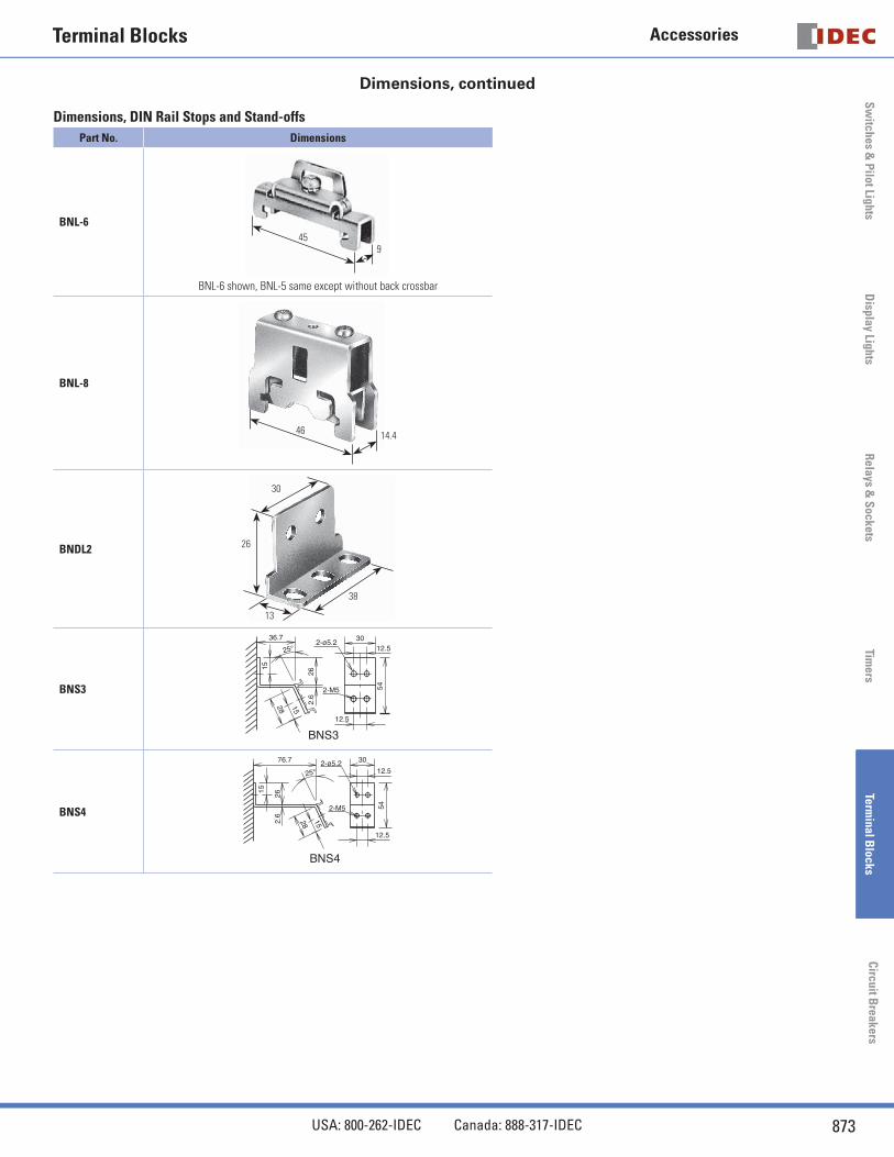
Dimensions, continued
Dimensions, DIN Rail Stops and Stand-offs
Part No. Dimensions
BNL-645
9
BNL-6 shown, BNL-5 same except without back crossbar
BNL-8
46 14.4
BNDL2
38
30
13
26
BNS3
BNS3
2-M5
2-ø5.236.7
25°
15
26
1528
12.530
12.5
54
2.6
BNS4
BNS4
2-M5
2-ø5.276.7
25°
15
26
1528
12.5
30
12.5
54
2.6
Terminal BlocksS
wit
ches
& P
ilot
Lig
hts
Rel
ays
& S
ocke
tsTi
mer
sTe
rmin
al B
lock
sC
ircu
it B
reak
ers
Accessories
874 www.idec.com
Sw
itch
es &
Pil
ot L
ight
sD
ispl
ay L
ight
sR
elay
s &
Soc
kets
Tim
ers
Term
inal
Blo
cks
Cir
cuit
Bre
aker
s
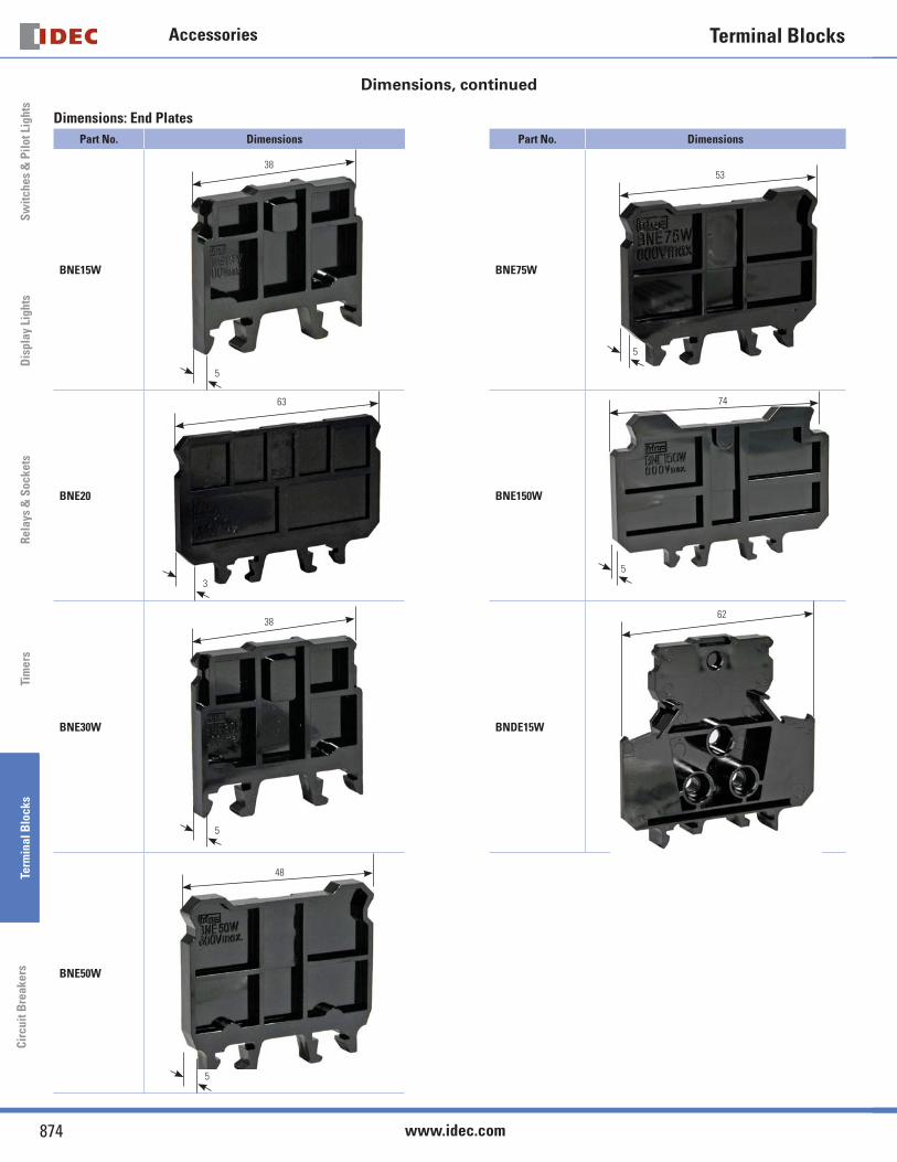
Dimensions, continued
Dimensions: End Plates
Part No. Dimensions Part No. Dimensions
BNE15W
38
5
BNE75W
53
5
BNE20
63
3
BNE150W
74
5
BNE30W
38
5
BNDE15W
62
BNE50W
48
5
Sw
itches & P
ilot LightsD
isplay LightsR
elays & S
ocketsTim
ersTerm
inal Blocks
Circuit B
reakers
Terminal Blocks Instructions
875USA: 800-262-IDEC Canada: 888-317-IDEC
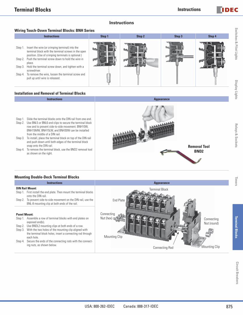
Instructions
Wiring Touch-Down Terminal Blocks: BNH Series
Instructions Step 1 Step 2 Step 3 Step 4
Step 1. Insert the wire (or crimping terminal) into the terminal block with the terminal screws in the open position. (Use of crimping terminals is optional.)
Step 2. Push the terminal screw down to hold the wire in place.
Step 3. Hold the terminal screw down, and tighten with a screwdriver.
Step 4. To remove the wire, loosen the terminal screw and pull up until wire is released.
Installation and Removal of Terminal Blocks
Instructions Appearance
Step 1. Slide the terminal blocks onto the DIN rail from one end. Step 2. Use BNL5 or BNL6 end clips to secure the terminal block
row and to prevent side-to-side movement. BNH10W, BNH15MW, BNH15LW, and BNH30W can be installed from the middle of a DIN rail.
Step 3. To install, place the terminal block on top of the DIN rail and push down until both edges of the terminal block snap onto the DIN rail.
Step 4. To remove the terminal block, use the BND2 removal tool as shown on the right.
Removal ToolBND2
Mounting Double-Deck Terminal Blocks
Instructions Appearance
DIN Rail Mount: Step 1. First install the end plate. Then mount the terminal blocks
onto the DIN rail. Step 2. To prevent side-to-side movement on the DIN rail, use the
BNL-8 mounting clip at both ends of the rail.
Terminal Block
End Plate
Connecting Nut (hex)
Mounting Clip
Connecting Rod Mounting Clip
Connecting Nut (round)
Panel Mount: Step 1. Assemble a row of terminal blocks with end plates on
exposed end(s). Step 2. Use BNDL2 mounting clips at both ends of a row.Step 3. With the two holes of the mounting clip aligned with
the terminal block holes, insert a connecting rod through each hole.
Step 4. Secure the ends of the connecting rods with the connect-ing nuts, as shown below.
Terminal BlocksS
wit
ches
& P
ilot
Lig
hts
Rel
ays
& S
ocke
tsTi
mer
sTe
rmin
al B
lock
sC
ircu
it B
reak
ers
Instructions
876 www.idec.com
Sw
itch
es &
Pil
ot L
ight
sD
ispl
ay L
ight
sR
elay
s &
Soc
kets
Tim
ers
Term
inal
Blo
cks
Cir
cuit
Bre
aker
s
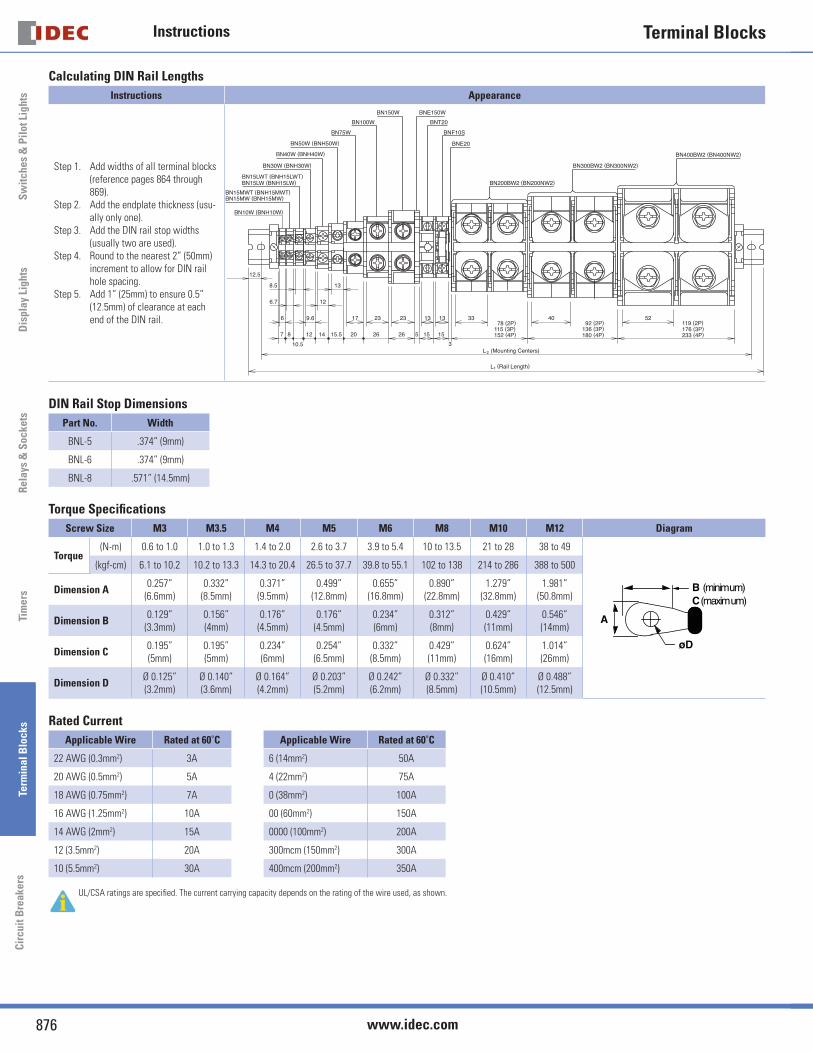
Calculating DIN Rail Lengths
Instructions Appearance
Step 1. Add widths of all terminal blocks (reference pages 864 through 869).
Step 2. Add the endplate thickness (usu-ally only one).
Step 3. Add the DIN rail stop widths (usually two are used).
Step 4. Round to the nearest 2” (50mm) increment to allow for DIN rail hole spacing.
Step 5. Add 1” (25mm) to ensure 0.5” (12.5mm) of clearance at each end of the DIN rail.
152 (4P)
78 (2P)176 (3P)233 (4P)
119 (2P)115 (3P)
92 (2P)136 (3P)180 (4P)
BN100W
BN15MW (BNH15MW)BN15MWT (BNH15MWT)
BN400BW2 (BN400NW2)
BN10W (BNH10W)
BN30W (BNH30W)
BN40W (BNH40W)
BN50W (BNH50W)
BN75W
BNT20
BN150W BNE150W
BNE20
BNF10S
BN15LWT (BNH15LWT)BN15LW (BNH15LW) BN200BW2 (BN200NW2)
BN300BW2 (BN300NW2)
52403313
15
13
15
23
526
23
26
17
20
13
15.5
12
1412
10.5
87
9.6
8.5
6.7
6
(Rail Length)L1
(Mounting Centers)L2
3
12.5
DIN Rail Stop Dimensions
Part No. Width
BNL-5 .374” (9mm)
BNL-6 .374” (9mm)
BNL-8 .571” (14.5mm)
Torque Specifi cations
Screw Size M3 M3.5 M4 M5 M6 M8 M10 M12 Diagram
Torque(N-m) 0.6 to 1.0 1.0 to 1.3 1.4 to 2.0 2.6 to 3.7 3.9 to 5.4 10 to 13.5 21 to 28 38 to 49
A
B (minimum)C (maximum)
øD
(kgf-cm) 6.1 to 10.2 10.2 to 13.3 14.3 to 20.4 26.5 to 37.7 39.8 to 55.1 102 to 138 214 to 286 388 to 500
Dimension A0.257”
(6.6mm)0.332”
(8.5mm)0.371”
(9.5mm)0.499”
(12.8mm)0.655”
(16.8mm)0.890”
(22.8mm)1.279”
(32.8mm)1.981”
(50.8mm)
Dimension B0.129”
(3.3mm)0.156” (4mm)
0.176” (4.5mm)
0.176” (4.5mm)
0.234” (6mm)
0.312” (8mm)
0.429” (11mm)
0.546” (14mm)
Dimension C0.195” (5mm)
0.195” (5mm)
0.234” (6mm)
0.254” (6.5mm)
0.332” (8.5mm)
0.429” (11mm)
0.624” (16mm)
1.014” (26mm)
Dimension DØ 0.125” (3.2mm)
Ø 0.140” (3.6mm)
Ø 0.164” (4.2mm)
Ø 0.203” (5.2mm)
Ø 0.242” (6.2mm)
Ø 0.332” (8.5mm)
Ø 0.410” (10.5mm)
Ø 0.488” (12.5mm)
Rated Current
Applicable Wire Rated at 60˚C Applicable Wire Rated at 60˚C
22 AWG (0.3mm2) 3A 6 (14mm2) 50A
20 AWG (0.5mm2) 5A 4 (22mm2) 75A
18 AWG (0.75mm2) 7A 0 (38mm2) 100A
16 AWG (1.25mm2) 10A 00 (60mm2) 150A
14 AWG (2mm2) 15A 0000 (100mm2) 200A
12 (3.5mm2) 20A 300mcm (150mm2) 300A
10 (5.5mm2) 30A 400mcm (200mm2) 350A
UL/CSA ratings are specifi ed. The current carrying capacity depends on the rating of the wire used, as shown.