OSAKI Factory Logistics OJT,...Title Fロジ(Factory Logistics)パンフレット Created Date 10/9/2019 1:03:57 PM

September, 2017Osaki Coolgen Corporation
The Progress of Osaki CoolGen Project~ Oxygen-blown Integrated Coal Gasification Fuel Cell
Combined Cycle Demonstration Project ~

Outline
1. Background and Significance of IGCC Development
2. Gasification Technology
3. Osaki Coolgen Project (1)Project Overview(2)Overview and Progress of IGCC
Demonstration(STEP1)(3) Demonstration Plan of IGCC with
CO2 Capture(STEP2)
1

Outline
1. Background and Significance of IGCC Development
2. Gasification Technology
3. Osaki Coolgen Project (1)Project Overview(2)Overview and Progress of IGCC
Demonstration(STEP1)(3) Demonstration Plan of IGCC with
CO2 Capture(STEP2)
2

Fuel price transitionCharacteristics of coal as energy resourceLow cost and stable supply compared to other fossil fuels
Distributed widely all over
the world
Abundance of reserves
Distribution of Coal resourcesProves reserves
1. Background
source:BP statistics2017 source:BP statistics2017
Oil
Gas
Coal
3

Percentage of each generation resource
Source:Energy balances of OECD countries 2016(IEA)/Energy balances of non-OECD countries 2016(IEA)
Coal ‒fired power generation accounts for about 40% of the world electricity generationThe coal-fired power generation is widely used in high energy-consuming countries
such as China, India and the US.
The proportion of coal-fired power generation is about 30% in Japan.
1. Background 4

Coal-fired power generation in the world : about 30% CO2 emission from Coal-fired power generation : about 30%
Coal-fired Power Generation- Current electricity & CO2 emission and 2040’s prospects -
Source: IEA World Energy Outlook 2015
Coal
gas
Source : IEA World Energy Outlook 2016(New Policies Scenario)
Electricity from coal-based power generation
41% (2014)
28% (2040)
CO2 emission from coal-based power generation
31% (2014)
27% (2040)
4 995 9 899 9 598 9 648 9 792 9 911 9 992
-
5 000
10 000
15 000
20 000
25 000
30 000
35 000
40 000
1990 2014 2020 2025 2030 2035 2040
CO
2 em
issi
on[M
t-CO
2]
Coal power Oil power Gas power Total CO2 emissions
1. Background 5

OECD America321GW→208GW
Latin America7GW→12GW
Other Asia Oceania184GW→367GW
China855GW→1,137GW
India176GW→451GW
Africa44GW→80GW
Middle East0GW→3GW
OECD Europe184GW→91GW
Eastern Europe/ Eurasia111GW→91GW
Source : IEA World Energy Outlook 2016(New Policies Scenario)
: 2014 : 2040
Prospects of the world Coal-fired power generation capacity
Coal-fired Power Generation- Current generation capacity and 2040’s prospects -
(2014) (2040)
Coal-fired power generation capacity in the world⇒ 1,882GW → 2,437GW (555GW)
1. Background 6

8
Coal-fired generation ⇒ Essential for the “Best Mix” energy policy Energy self-sufficiency in Japan= approx. 6%*
Coal-fired Power Generation
Demand of electric power Composition of electrical source
966.6TWh 980.8TWh
Coal:26%
LNG:27%
Nuclear:22-20%
Renewable :22-24%
Geothermal :1.0-1.1%
Wind :1.7%
PV :7.0
Hydro:8.8-9.2%
Biomass :3.7-4.5%
1065TWh
Oil:3%FY2030 FY2030FY2013
Economic growth
Energy Mix in Japan**Saving energy196.1TWh
1. Background
- status in Japan -
**Source : METI Long-term energy supply-demand outlook(2015.7)*Source : Japan’s Energy White Paper 2016

Efficiency :Net / Higher heating value
Ultra SC(USC)
Super critical(SC)
Advanced USC(A-USC)
46 ~ 48%CO2 reduction about ▲15%
1300℃ IGCC 1500℃ IGCC 1700℃ IGCC
(MCFC)(SOFC)
Fuel Cell(FC)Integrated coal gasification fuel
cell combined cycle (IGFC)
Integrated coal gasification combined cycle(IGCC)
Pulverized coal fired(PCF)
55%~CO2 reduction about ▲30%)
Gas turbinegasifier
HRSG
Steam turbine
boiler
Steam turbine
gasifier Gas turbineFuel cell
HRSG
Steam turbine
Development Road Map of High Efficiency Low Emissions Coal Power Generation Technology in Japan
39 ~ 41%base
38% 46 ~ 48%
1. Background 8

We must:
Efficiently use low cost coal for increased Power Demand Drastically reduce CO2 emissions against Global Warming
(Step-1)
Significance of Osaki Coolgen Project
IGCC + CO2 Capture(Step-2)
Oxygen-blown IGCC with high efficiency, high environment-tal performance, reliability, coal variety compatibility and controllability
IGFC + CO2 Capture
Osaki Coolgen Demonstration Project
Development of High Efficient Clean Coal Technology
(Step-3)
Coal is indispensable to achieve sustainable power supply
Global Sustainable Development
In Resources Importing Countries (as Japan)
1. Significance 9

Outline
1. Background and Significance of IGCC Development
2. Gasification Technology
3. Osaki Coolgen Project (1)Project Overview(2)Overview and Progress of IGCC
Demonstration(STEP1)(3) Demonstration Plan of IGCC with
CO2 Capture(STEP2)
10

2. Gasification Technology
Significance of developing Oxygen blown type “EAGLE” Gasifier
High efficiency and low carbonization of coal-fired power generation and effective utilization of coal and its byproduct
Drastically to improve power generation efficiency and significantly to reduce carbon dioxide emission.
Efficiently to capture CO2 by pre-combustion method.
To use low-grade coal(sub-bituminous coal and brown coal) and high-grade coal(bituminous coal) for gasification.
To re-use coal ash and reduce in volume as slug of glass type
Multi-purpose uses of coal gasification gasFor the gasification gas to be widely used as synthetic fuels and chemical raw materials.
11

Process Development Unit(1t/d/FY1981~1985/Katsuta)
HYCOL Pilot Plant(50t/d/FY1991~1993/Sodegaura)
EAGLE Pilot Plant(150t/d/FY2002~2013/Wakamatsu)
OCG Demonstration Plant(1,180t/d/FY2016~
166MW/Osaki)
Coal Energy Application for Gas, Liquid, and Electricity
× 3
× 8
Scale Up
2. Gasification TechnologyDevelopment History and Significance of “EAGLE” Gasifier of Oxygen Blown Type
12

Features of EAGLE GasifierOxygen-blown Two-stage Spiral-flow Gasifier
2. Gasification Technology 13

0.50
1.00
1.50
2.00
2.50
1150 1200 1250 1300 1350 1400 1450 1500 1550 1600 1650 1700
Ash Melting Temperature [℃]
Fixed carbon/Volatile matter [-]
Conventional Gasifier
Pulverizing Coal FiredEAGLE Gasifier
◆、◆:EAGLE AchievementPilot Project
Applicable Coal types for the “EAGLE ” gasifierEAGLE
Source : JPOWER EAGLE brochure
Coals appropriate for Gasification
Pulverizing Coal Fired
Sub bituminous Coal area Bituminous Coal area:EAGLE Pilot Project Achievement
2. Gasification Technology 14

Outline
1. Background and Significance of IGCC Development
2. Gasification Technology
3. Osaki Coolgen Project (1)Project Overview(2)Overview and Progress of IGCC
Demonstration(STEP1)(3) Demonstration Plan of IGCC with
CO2 Capture(STEP2)
15

Project Timeline
Coal
GTCompressorN2
O2
Fuel Cell
ASU
CO2
Gasifier Gas Clean up
H2
Step-2
CO, H2
このイメージは、現在表示できません。このイメージは、現在表示できません。
Step-1
Step-3GeneratorST
(1)Project Overview 16

METI (~FY2015): Ministry of Economy, Trade and IndustryNEDO (FY2016~):New Energy and Industrial Technology Development Organization
OSAKI CoolGen Corporation
The Chugoku Electric Power Co., Inc. (Energia)Electric Power Development Co., Ltd. (J-POWER)
Subsidy
Mitsubishi Hitachi Power Systems, LTD.Coal gasifier unitCombined cycle unitCoordinate all units
STEP1 EPC contract
JGC Corporation
Gas clean up unitWastewater treatmentAir separation unit
DiamondEngineering Co . Ltd.Coal preparation & supply unit
Project Scheme
Joint Investment
STEP1 EPC contract STEP1 EPC contract
(1)Project Overview 17

Outline
1. Background and Significance of IGCC Development
2. Gasification Technology
3. Osaki Coolgen Project (1)Project Overview(2)Overview and Progress of IGCC
Demonstration(STEP1)(3) Demonstration Plan of IGCC with
CO2 Capture(STEP2)
18

IGCC Process Flow
Air
Combined cycle unit
Cooling Water
ST
Condenser
HRSG
GGT
Combustor
CycloneFilter
Coal gasification unit
Nitrogen
Air
Compressor
Gas clean-up unit
Coal
Mill
Hopper
slag
#1Water
scrubber
Stack
Oxygen
Rectifier
Air separation unit
GasifierSyngascooler
COSconverter
Acid gasremoval
Limestoneabsorber
Acid gasfurnace
Air
Calciumsulfate
Waste water treatment
Sludge
Treat waterWaste water
Sulfur recovery unit
LPGAir
Flare unit#2
Waterscrubber
DeNOx
Compressor
(2)Overview and Progress(STEP-1) 19

Specification
Coal Gasification UnitOxygen-Blown Single-Chamber Two-Staged Spiral-Flow Entrained Bed Coal feed :1,180 ton/day
Gas Clean-up Unit Wet Desulfurization Unit : Methyl Di-Ethanol
Amine (MDEA)Sulfur Recovery Unit : Limestone Wet Scrubbing
Air Separation Unit Pressurized Cryogenic Separation
Combined Cycle Unit GT (MHPS : H100 TIT=1300°C class,
adopted Multi-Cluster burner)Gross Power Output : 166MW (GT+ST)
Wastewater Treatment Unit Gas Clean-up Unit Wastewater Treatment
Major Specifications(2)Overview and Progress(STEP-1) 20

STEP1 DemonstrationTargetsItem Targets
EfficiencyTop class Net Efficiency 40.5% (HHV), 42.7%(LHV)Equivalent to Net efficiency 46%(HHV), 48%(LHV) ,when applied to1,500℃ class GT(already developed) in a commercial plant (higher output)
Emission Level
Top class environmental performanceSOx : 8ppmNOx : 5ppmParticulate : 3mg/m3N (as 16%O2 equivalent)
Coal Variety Compatibility Applicable to varieties of coal with various ash fusion temperature
Plant Reliability Aiming at more than 70%/year availability by 5000hrs operation test.
PlantControllability &
OperabilityLoad ramp rate : 1-3%/min.
Economy To obtain the prospect that the COE (cost of electricity) of IGCC is thesame level as that of USC.
(2)Overview and Progress(STEP-1) 21

IGCC Construction Progress
FY 2012 2013 2014 2015 2016 2017 2018
MajorEvents
▼Start of Civil w
ork
▼Power receiving for com
missioning
▼Gasifierstart-up by coal
▼Start of demonstration
OperationDesign, Manufacturing, Construction,
▼HR
SG on site
▼Gasifier on site
▼SGC
on site
▼Gas cleanup unit on site
▼ASU
on site
▼Pressurization test of piping
▼Gas turbine
start-up
MarJulAprNovJulJanDecDecNovMayMar
(2)Overview and Progress(STEP-1) 22

Mechanical completion
Existing PlantChugoku electric power co.
Osaki PS 1-1
Gasification
Gas Clean up
Air Separation
Combined Cycle
Waste Water Treatment
Sulfur Recovery
(13th April 2016)
(2)Overview and Progress(STEP-1) 23

Gas Clean Up Unit(2)Overview and Progress(STEP-1) 24

Combined cycle Unit(2)Overview and Progress(STEP-1) 25

Air separation Unit(2)Overview and Progress(STEP-1) 26

STEP1:Commissioning results and demonstration planFY 2015 2016 2017 2018
Individual machinery and system test
Integrated C
omm
issioning
GT no load testCoal gasification testload dump testload dump test,Relief valve testGasifier/GT characteristic test Automatic plant control adjustmentTest of heat run and performanceTest of automatic plant start-up/shut down D
emonstration
・Verification of basic performanceand reliability・Verification of compatibility of coal variety・Verification of controllability
resultsplanresultsplan
Power generation Gross output
GasifierOperating hours
Continuous Operating hours
Operating data(AS of July ,2017) 300,638 MWh 2,415 h 514 h
27(2)Overview and Progress(STEP-1)
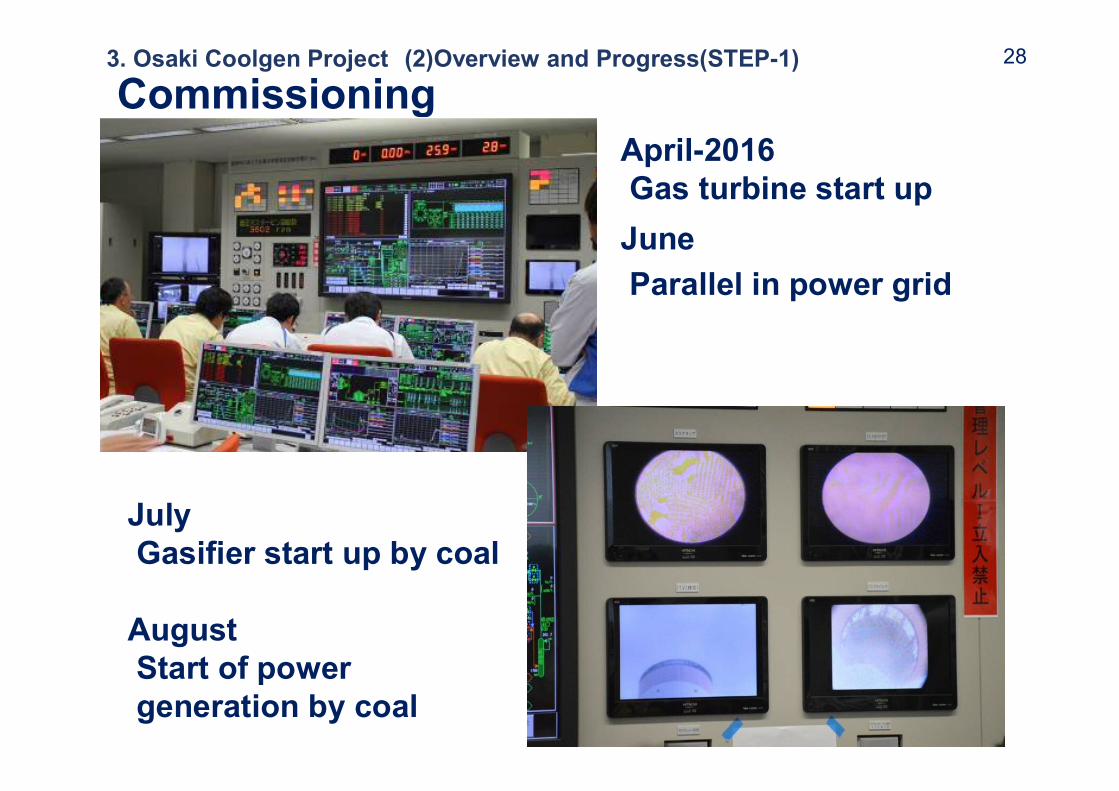
CommissioningApril-2016Gas turbine start upJuneParallel in power grid
JulyGasifier start up by coal
AugustStart of power generation by coal
283. Osaki Coolgen Project (2)Overview and Progress(STEP-1)

CommissioningNovemberAchievementGasifier load : 100%Power generation : 166MW (100%)
March-2017Start of Demonstration
293. Osaki Coolgen Project (2)Overview and Progress(STEP-1)
August-2017Completion Ceremony

Outline
1. Background and Significance of IGCC Development
2. Gasification Technology
3. Osaki Coolgen Project (1)Project Overview(2)Overview and Progress of IGCC
Demonstration(STEP1)(3) Demonstration Plan of IGCC with
CO2 Capture(STEP2)
30

STEP2 / CO2 Capture test (FY 2016-2020)
Coal
N2
O2steam Sour Shift Reactor
(low temprature catalyst)
gas clean up unit
steam
CO2Sweet shift reactorsCO+H2O ⇒ CO2+H2
CO, H2
CO2, H2
H2Absorber
CO2 Flash drums
CO2 capture unit(17% s lipstream test)
Sour Shift Catalyst Pilot Test unit
IGCC
Air separation unit
Gasifier
Scrubber MDEA
Physical absorption
Sour Shift Catalyst pilot testFeed Gas Sour Shift
(Upstream of desulfurization)
CO2 Capture testFeed Gas 17% slipstream
syngas equivalent to 15% of total CO2 volume
CO2Capturemethod
Physical absorption
CO shift section
Sweet Shift (Downstream of desulfurization)
Air Separation unit
CO2 Capture unit
Sweet Shift ReactorsCO + H2O → CO2 + H2
Steam
Steam
CO2 Flash Drums
Physical Absorption
Gas Clean-up unit
N2
O2
CO, H2
CO2, H2
H2
CO2
Sour Shift Reactor(Low temperature)
(3) Demonstration Plan of IGCC with CO2 Capture (STEP-2) 31
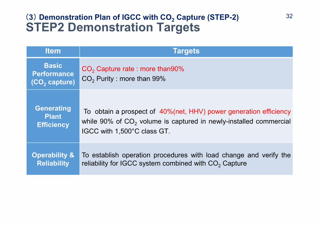
Item Targets
Basic Performance(CO2 capture)
CO2 Capture rate : more than90%CO2 Purity : more than 99%
GeneratingPlant
Efficiency
To obtain a prospect of 40%(net, HHV) power generation efficiencywhile 90% of CO2 volume is captured in newly-installed commercialIGCC with 1,500°C class GT.
Operability & Reliability
To establish operation procedures with load change and verify thereliability for IGCC system combined with CO2 Capture
STEP2 Demonstration Targets(3) Demonstration Plan of IGCC with CO2 Capture (STEP-2) 32

33