The Preventive Maintenance Manual - Virginia Department of
146
September 28, 2012 (Revised 12-02-15) PREVENTIVE MAINTENANCE MANUAL FOR VIRGINIA SCHOOL BUSES Virginia Department of Education
Transcript of The Preventive Maintenance Manual - Virginia Department of

September 28, 2012 (Revised 12-02-15)
PREVENTIVE MAINTENANCE MANUAL
FOR VIRGINIA SCHOOL BUSES
Virginia Department of Education
2
FOREWORD
The purpose of this publication is to provide information regarding
preventive maintenance, which is essential to the safe and efficient
operation of school buses. An effective maintenance program can reduce
accidents, downtime, and maintenance costs, as well as improve driver
morale and public relations.
The driver’s daily pre-trip inspection is the first step in preventive
maintenance. Proper training and supervision are needed to make drivers
aware of their responsibilities. An open line of communication among
drivers, bus shop personnel, and school administrators is a must.
To control losses and protect a school division’s investment in a fleet of
buses, it is important to inspect and maintain all school buses
systematically and conscientiously.
Accurate maintenance records are essential in determining the
effectiveness of a preventive maintenance program.
This publication should prove helpful to persons initiating preventive
maintenance programs or considering changes to existing programs.
3
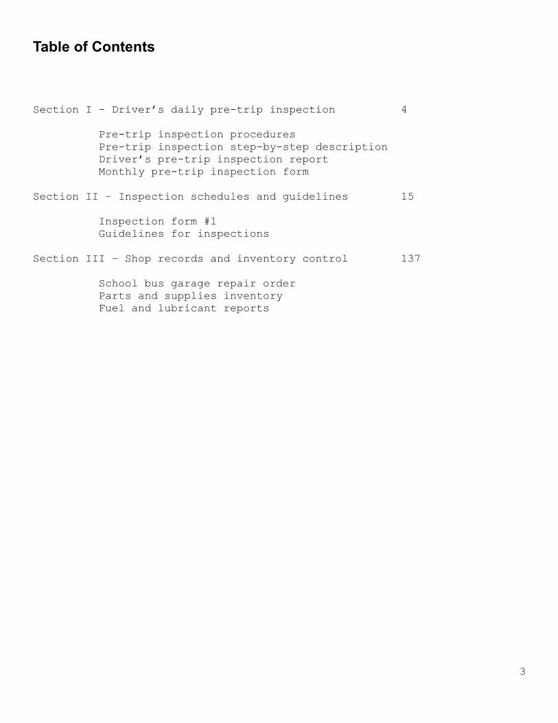
Table of Contents
Section I – Driver’s daily pre-trip inspection 4
Pre-trip inspection procedures
Pre-trip inspection step-by-step description
Driver’s pre-trip inspection report
Monthly pre-trip inspection form
Section II – Inspection schedules and guidelines 15
Inspection form #1
Guidelines for inspections
Section III – Shop records and inventory control 137
School bus garage repair order
Parts and supplies inventory
Fuel and lubricant reports

4
SECTION I
DRIVER’S DAILY PRE-TRIP INSPECTION
Drivers are a critical component of an effective school bus preventive
maintenance program. While the technician sees a bus periodically, the
driver uses that bus every day. By making effective inspections before
each daily trip and noticing how the bus performs during each trip, the
driver often can detect early signs of developing mechanical problems.
Drivers are responsible for checking, recording, and reporting the
mechanical condition of their buses. The Regulations Governing Pupil
Transportation state:
8 VAC 20-70-380. Pre-trip safety inspection. “Prior to the initial transporting of children each day, the drivers of
school and activity buses shall perform a daily pre-trip safety inspection
of the vehicle. The items checked and recorded shall be at least equal to
the pre-trip inspection procedure in the Preventive Maintenance Manual for
Virginia School Buses issued by the Department of Education.”
Regardless of whether drivers find any defects, they should submit written
bus condition reports that are accurate and complete.
Included in this publication are sample forms to be used in inspecting and
reporting defects daily and monthly. Procedures in excess of those
required by regulation for reporting the condition of school buses should
be established to meet the needs of individual divisions.

5
DAILY PRE-TRIP INSPECTION PROCEDURES
A. FRONT OF BUS G. UNDER BUS (Driver Side) 1. Check Under Bus for Leaks 1. Check: 2. In the Engine Compartment, Check: a. Drive Shaft & Guards
a. Oil Level b. Exhaust System b. Coolant Level c. Frame c. Power Steering Fluid Level H. LEFT REAR WHEEL (Driver Side) d. Water Pump Looseness 1. Check: e. Alternator Looseness a. Hub Oil Seal f. Air Compressor Looseness b. Rims & Lug Nuts g. Air Leaks c. Tires & Treads h. Brake Master Cylinder Leaks d. Spring & Mounts i. All Belts e. Shock Absorber
B. INSIDE BUS f. Air Brake Slack Adjuster & Chamber 1. Start Engine & Check: g. All Brake Hoses
a. Oil Pressure h. Drum or Roter b. Alternator Voltage/Amps I. REAR OF BUS c. Air Pressure & Air Brake Check 1. Check d. Steering Play a. All Lights e. Parking Brake b. All Reflectors f. All Mirrors & Windshield c. Rear Emergency Door/Exit g. Wipers & Washers J. RIGHT REAR WHEEL (Entrance Door Side) h. Light Indicators 1. Check: i. Horn(s) a. Hub Oil Seal j. Heaters & Defrosters b. Rim & Lug Nuts k. All Safety Equipment c. Tire & Tread
C. TURN ON ALL LIGHTS & EXIT BUS d. Spring & Mounts D. START AT RIGHT FRONT WHEEL (Entrance Door Side) e. Shock Absorber
1. Check: f. Air Brake Slack Adjuster & Chamber a. Hub Oil Seal g. All Brake Hoses b. Rim & Lug Nuts h. Drum or Rotor c. Tire & Tread K. FUEL AREA d. Spring & Mounts 1. Check: e. Shock Absorber a. Fuel Tank f. Air Brake Slack Adjuster & Chamber b. Fuel Leaks g. All Brake Hoses L. PASSENGER AREA INSIDE BUS h. Drum or Rotor 1. Check:
E. GO TO FRONT OF BUS a. Entrance Door 1. Check: b. Handrail(s), Steps & Step Well
a. Entrance Door & All Front Mirrors c. All Seats b. All Front Lights d. All Emergency Exits
F. LEFT FRONT WHEEL/AREA (Driver side) e. All Emergency Equipment 1. Check: M. FINAL CHECKS
a. Hub Oil Seal 1. Check: b. Rim & Lug Nuts a. Brake & Back-up Lights c. Tire & Tread b. Transmission & Clutch d. Spring & Mounts c. Brakes e. Shock Absorber d. Steering f. Air Brake Slack Adjuster & Chamber g. All Brake Hoses h. Drum or Rotor i. Steering Box j. Steering Linkage
6
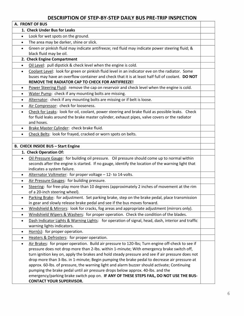
DESCRIPTION OF STEP-BY-STEP DAILY BUS PRE-TRIP INSPECTION A. FRONT OF BUS
1. Check Under Bus for Leaks Look for wet spots on the ground. The area may be darker, shine or slick. Green or pinkish fluid may indicate antifreeze; red fluid may indicate power steering fluid; &
black fluid may be oil.
2. Check Engine Compartment Oil Level: pull dipstick & check level when the engine is cold. Coolant Level: look for green or pinkish fluid level in an indicator eve on the radiator. Some
buses may have an overflow container and check that it is at least half full of coolant. DO NOT REMOVE THE RADIATOR CAP TO CHECK FOR ANTIFREEZE!
Power Steering Fluid: remove the cap on reservoir and check level when the engine is cold. Water Pump: check if any mounting bolts are missing. Alternator: check if any mounting bolts are missing or if belt is loose. Air Compressor: check for looseness. Check for Leaks: look for oil, coolant, power steering and brake fluid as possible leaks. Check
for fluid leaks around the brake master cylinder, exhaust pipes, valve covers or the radiator and hoses.
Brake Master Cylinder: check brake fluid. Check Belts: look for frayed, cracked or worn spots on belts.
B. CHECK INSIDE BUS – Start Engine
1. Check Operation Of: Oil Pressure Gauge: for building oil pressure. Oil pressure should come up to normal within
seconds after the engine is started. If no gauge, identify the location of the warning light that indicates a system failure.
Alternator Voltmeter: for proper voltage – 12- to 14-volts. Air Pressure Gauges: for building pressure. Steering: for free-play more than 10 degrees (approximately 2 inches of movement at the rim
of a 20-inch steering wheel).
Parking Brake: for adjustment. Set parking brake, step on the brake pedal, place transmission in gear and slowly release brake pedal and see if the bus moves forward.
Windshield & Mirrors: look for cracks, fog areas and appropriate adjustment (mirrors only). Windshield Wipers & Washers: for proper operation. Check the condition of the blades. Dash Indicator Lights & Warning Lights: for operation of signal, head, dash, interior and traffic
warning lights indicators.
Horn(s): for proper operation. Heaters & Defrosters: for proper operation. Air Brakes: for proper operation. Build air pressure to 120-lbs; Turn engine off-check to see if
pressure does not drop more than 2-lbs. within 1-minute; With emergency brake switch off, turn ignition key on, apply the brakes and hold steady pressure and see if air pressure does not drop more than 3-lbs. in 1-minute; Begin pumping the brake pedal to decrease air pressure-at approx. 60-lbs. of pressure, the warning light and alarm buzzer should activate; Continuing pumping the brake pedal until air pressure drops below approx. 40-lbs. and the emergency/parking brake switch pop on. IF ANY OF THESE STEPS FAIL, DO NOT USE THE BUS-CONTACT YOUR SUPERVISOR.

7
DESCRIPTION OF STEP-BY-STEP BUS DAILY PRE-TRIP INSPECTION (Page 2)
C. CHECK LIGHTS ON OUTSIDE OF BUS Turn on headlights, clearance, 4-way hazard, and traffic warning lights. Exit bus with engine idling, transmission in neutral and park/emergency brake set.
D. RIGHT FRONT WHEEL (Entrance Door Side)
1. Check For: Hub Oil Seal: grease/oil leaking from seal. Look for bolts missing. Lug Nuts: missing or loose lug nuts. Look for rust around the lug nuts. Rim: cracks, indentations or welds. Tire: cuts, wear bars, knots or any other imperfections in the tire. Tread depth must be a
minimum of 4/32-inch (1/8-inch) in the major groove of the tire.
Spring and Mounts: broken spring leaves; look at U-bolts and spring hangers for cracks, looseness or missing cotter keys.
Shock Absorber(s): oil running from the shock absorber or wet area on bottom and missing bolts.
Air Brake Slack Adjuster: missing cotter keys on the pins. Look and see that the adjuster is set at 90° (all adjusters must be at the same angle at all wheels).
Air Brake Chamber: loose or missing bolts. Check for rust around the chamber. Brake Hoses: frayed, cracked or rubbing hoses. Check for wet or shiny areas on hoses and/or
hose fittings.
Drum or Rotor: cracks or missing pieces.
E. FRONT OF BUS
1. Check For: Mirror at Entrance Door: broken brackets or missing bolts; shake and see if it is loose. Lights: proper operation of headlights, 4-way hazard, clearance and traffic warning lights;
check for cracked or missing light covers.
Crossing Arm: proper operation and in the extended position. Crossing Mirrors: broken brackets or missing bolts; shake and see if they are loose. Stop Sign(s): proper operation and in the extended position; check the operation of the
flashing lights.
F. LEFT FRONT WHEEL/AREA (Driver Side)
1. Check For: Hub Oil Seal: grease/oil leaking from seal. Look for bolts missing. Lug Nuts: missing or loose lug nuts. Look for rust around the lug nuts. Rim: cracks, indentations or welds. Tire: cuts, wear bars, knots or any other imperfections in the tire. Tread depth must be a
minimum of 4/32-inch (1/8-inch) in the major groove of the tire.
Spring and Mounts: broken spring leaves; look at U-bolts and spring hangers for cracks, looseness or missing cotter keys.
Shock Absorber(s): oil running from the shock absorber or wet area on bottom and missing bolts.
Air Brake Slack Adjuster: missing cotter keys on the pins. Look and see that the adjuster is set at 90° (all adjusters must be at the same angle at all wheels).
Air Brake Chamber: loose or missing bolts. Check for rust around the chamber.
8
DESCRIPTION OF STEP-BY-STEP BUS DAILY PRE-TRIP INSPECTION (Page 3)
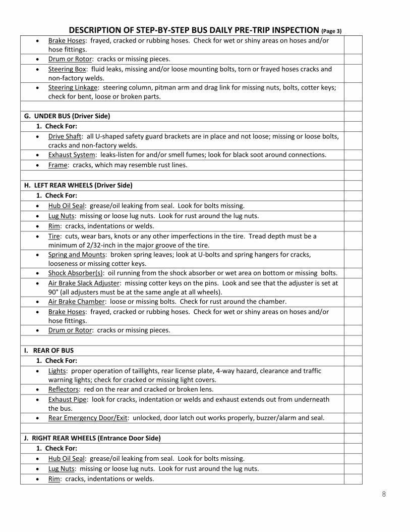
Brake Hoses: frayed, cracked or rubbing hoses. Check for wet or shiny areas on hoses and/or hose fittings.
Drum or Rotor: cracks or missing pieces. Steering Box: fluid leaks, missing and/or loose mounting bolts, torn or frayed hoses cracks and
non-factory welds.
Steering Linkage: steering column, pitman arm and drag link for missing nuts, bolts, cotter keys; check for bent, loose or broken parts.
G. UNDER BUS (Driver Side)
1. Check For: Drive Shaft: all U-shaped safety guard brackets are in place and not loose; missing or loose bolts,
cracks and non-factory welds.
Exhaust System: leaks-listen for and/or smell fumes; look for black soot around connections. Frame: cracks, which may resemble rust lines.
H. LEFT REAR WHEELS (Driver Side)
1. Check For: Hub Oil Seal: grease/oil leaking from seal. Look for bolts missing. Lug Nuts: missing or loose lug nuts. Look for rust around the lug nuts. Rim: cracks, indentations or welds. Tire: cuts, wear bars, knots or any other imperfections in the tire. Tread depth must be a
minimum of 2/32-inch in the major groove of the tire.
Spring and Mounts: broken spring leaves; look at U-bolts and spring hangers for cracks, looseness or missing cotter keys.
Shock Absorber(s): oil running from the shock absorber or wet area on bottom or missing bolts. Air Brake Slack Adjuster: missing cotter keys on the pins. Look and see that the adjuster is set at
90° (all adjusters must be at the same angle at all wheels).
Air Brake Chamber: loose or missing bolts. Check for rust around the chamber. Brake Hoses: frayed, cracked or rubbing hoses. Check for wet or shiny areas on hoses and/or
hose fittings.
Drum or Rotor: cracks or missing pieces.
I. REAR OF BUS 1. Check For: Lights: proper operation of taillights, rear license plate, 4-way hazard, clearance and traffic
warning lights; check for cracked or missing light covers.
Reflectors: red on the rear and cracked or broken lens. Exhaust Pipe: look for cracks, indentation or welds and exhaust extends out from underneath
the bus.
Rear Emergency Door/Exit: unlocked, door latch out works properly, buzzer/alarm and seal.
J. RIGHT REAR WHEELS (Entrance Door Side) 1. Check For: Hub Oil Seal: grease/oil leaking from seal. Look for bolts missing. Lug Nuts: missing or loose lug nuts. Look for rust around the lug nuts. Rim: cracks, indentations or welds.

9
DESCRIPTION OF STEP-BY-STEP BUS DAILY PRE-TRIP INSPECTION (Page 4)
Tire: cuts, wear bars, knots or any other imperfections in the tire. Tread depth must be a minimum of 2/32-inch in the major groove of the tire.
Spring and Mounts: broken spring leaves; look at U-bolts and spring hangers for cracks, looseness or missing cotter keys.
Shock Absorber(s): oil running from the shock absorber or wet area on bottom and missing bolts.
Air Brake Slack Adjuster: missing cotter keys on the pins. Look and see that the adjuster is set at 90° ( all adjusters must be at the same angle at all wheels).
Air Brake Chamber: loose or missing bolts. Check for rust around the chamber. Brake Hoses: frayed, cracked or rubbing hoses. Check for wet or shiny areas on hoses and/or
hose fittings.
Drum or Rotor: cracks or missing pieces.
K. FUEL AREA
1. Check For: Fuel Tank: fuel cap is properly mounted on fuel tank; the gasket on the cap; and loose parts,
cracks or missing pieces of the fuel tank safety cage.
Fuel Leaks: Be alert to fume smells and look for fuel spills on the ground.
L. PASSENGER AREA INSIDE BUS
1. Check For: Entrance Door: broken glass and proper operation (closing and opening). Step Treads: treads securely fastened and not posing a tripping hazard; area open and free of
any objects or articles.
Handrail(s): looseness, missing bolts and catch-points. Passenger Seats: loose seats; walk to the back of the bus, grab the back corner of each bottom
seat and pull up to see if they are properly attached; check for cuts or torn seat covers.
All Emergency Doors & Exits: all doors, windows and roof emergency exits are unlocked; open each to check their alarm buzzer. If equipped with a Folding Seat (at a side emergency door) check for proper fold-up operation.
Passenger Seat Backs: loosen or broken frames and/or mounts; check each seat by grabbing the top corner of the seat and shake to see if it is loose or broken.
Windows: cracked or broken glass; check for the proper operation of the windows. Emergency Equipment: the proper size and type fire extinguisher is fully charged and properly
secured on a bracket; the first aid and body fluids kits are properly mounted and contain required contents; the triangle reflective markers kit contains 3-markers and properly secured; and the web cutter is properly mounted.
M. FINAL CHECKS
1. Check For: Brake, Back-Up and Turn Signal Lights: proper operation of the lights. Depress the brake
pedal, place the bus in reverse gear and look for the red reflections of the brake lights, the reflections of the back-up lights and listen for the back-up alarm.
Clutch & Transmission: start the bus and put the bus in gear, release the clutch and check for proper engagement.
Brakes: pull the bus forward and depress the brake pedal to check for proper stopping ability. Steering: operate the steering wheel back and forth to check for proper control.

10
BUS DRIVER’S DAILY PRE-TRIP INSPECTION REPORT
School Division: ___________________________________ Bus #:______________
Odometer Reading: ________________________ Date: _______________
INSPECT ALL ITEMS LISTED – IF DEFECTIVE, MARK (“X”) & DESCRIBE IN ‘REMARKS’
CHECK ITEMS BELOW: X CHECK ITEMS BELOW: X
Fluid Leaks Under Bus Cleanliness of Interior & Exterior
Loose Wires or Hose Connections Emergency Doors, Exits & Buzzers
Belts in Engine Compartment Front Traffic Warning Lights
Oil Level Headlights, Signal & 4-Way Lights
Radiator Coolant Level Front of Bus – Windshield
Power Steering Fluid
Left Front Tire, Wheel & Rim & Suspension
Battery Stop Arm(s) – Sign(s) & Lights
Transmission
Ride Front Tires, Wheels, Rims & Suspension
Clutch Exhaust System
Unusual Engine Noise Left Side of Bus – Windows & Lights
Gauges & Warning Lights
Left Rear Tires, Wheels, Rims & Suspension
Switches Rear of Bus – Windows & Lights
Horn
Right Rear Tires, Wheels, Rims & Suspension
Fans & Defrosters Right Side of Bus – Windows & Lights
Wipers & Washers Drive Shaft & Guards
Stop Sign(s) & Crossing Arm Controls Lettering & Paint
All Outside and Inside Mirrors Driver’s Seat & Belt
Brake Pedal & Warning Light All Seats and Belts
Controls & Operation of Entrance Door Brakes: Parking & Service
Emergency Equipment Steering
First Aid & Body Fluids Kits Wheelchair Lift Controls & Operation
Entrance Door/Entrance Steps and Handles Tie-Downs & Securement Equipment
Fuel Tank DRIVER REMARKS:
_____________________________________________________________________________________ _____________________________________________________________________________________ _____________________________________________________________________________________
[If repairs are indicated above, follow local procedures] ____________________________________ __________________________________________ Print Driver’s Name Driver’s Signature ___________________________________________________ Supervisor’s Signature & Date
11
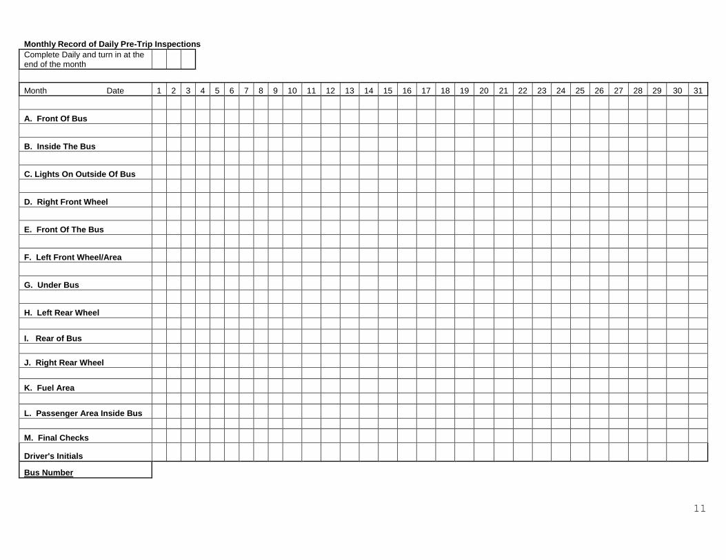
Monthly Record of Daily Pre-Trip Inspections
Complete Daily and turn in at the end of the month
Month Date 1 2 3 4 5 6 7 8 9 10 11 12 13 14 15 16 17 18 19 20 21 22 23 24 25 26 27 28 29 30 31
A. Front Of Bus
B. Inside The Bus
C. Lights On Outside Of Bus
D. Right Front Wheel
E. Front Of The Bus
F. Left Front Wheel/Area
G. Under Bus
H. Left Rear Wheel
I. Rear of Bus
J. Right Rear Wheel
K. Fuel Area
L. Passenger Area Inside Bus
M. Final Checks
Driver's Initials
Bus Number

12
SECTION II
INSPECTION SCHEDULES AND GUIDELINES
The purpose of this section is to assist personnel who are
responsible for the maintenance of school buses by providing
schedules, checklists, and guidelines governing inspections.
The Inspection Checklist is used for inspections performed at the
times indicated in the manual. Such inspections are required by
the Board of Education as stated in the Regulations Governing
Pupil Transportation.
8VAC 20-70-130. Maintenance inspection.
“All school buses and school activity buses used to transport
public school pupils to and from school and school activity events
shall be inspected and maintained by competent mechanics at least
once every 45 school days, with “school days” as determined by the
school division’s approved yearly calendar or modifications in the
calendar as approved by the division superintendent or designee,
or every 5,000 miles. Any bus that is removed from service or
deadlined so as to disrupt the scheduled maintenance shall be
inspected prior to being returned to service. At no point shall
any bus go without an inspection during the school semester and
such inspections shall be no more than 90 school days apart
excluding summer sessions. The inspections and maintenance shall
be conducted in accordance with provisions of the Preventive
Maintenance Manual for Virginia School Buses, and recorded on the
prescribed inspection forms or in a format approved by the
Department of Education. Additional Original Equipment
Manufacturer (OEM) inspection and maintenance recommendations
should be maintained during the service life of each bus to ensure
safety and warranty requirements are met. Maintenance
consideration should be given to buses operated during the summer
session. If the inspection and maintenance are not made in a shop
operated by the school board or the local governing body, the
school board shall designate one or more inspection centers to
make the inspections and require a copy of the results of the
inspections to be furnished to the division superintendent.
School division compliance with the foregoing maintenance
inspection requirements shall be subject to verification by the
Department of Education.
Guidelines for inspection include recommended “Out-of-Service”
criteria that should be used as a best practice and minimum
standard of inspection as outlined in Annual Motor Vehicle
Inspection Manual of the Virginia State Police (19 VAC30-70-1). In
any instance where the inspection outlined in this manual appears

13
to be less than those standards as outlined by the Virginia State
Police inspection manual, the standards of the Virginia State
Police should take precedent.
Completion of the Inspection form requires that conditions be
recorded as follows:
(/)= “OK” no defects with the vehicle and it is safe to operate.
(M)= “Repair made” defects that were able to be corrected during
the inspection. Recording of this category allows inspectors to
see if there is a trend of defects on particular vehicles or
vehicle operation.
(N)= “Repair needed” defects that could not be immediately
corrected but does not affect the safe operation of the vehicle
and does not create an “Out-of-Service” condition.
(O)= “Out-of-Service” defects which could affect the safe
operation of the vehicle. Vehicles placed in an “Out-Of Service”
status must not be allowed to operate until appropriate repairs
have been made to correct the defect.
Items outlined in this manual are not all inclusive and may not
include all safety items applicable to a particular vehicle.
14

15
Inspection Procedures: Repair if: Recommended Out of Service
if:
1. Starter Action.
a. Check whether starter turns engine at normal
speed.
b. Check for snappy action, noise and operation of
starter drive.
Engine will not start or is
difficult to start.
2. Engine Operation.
a. Check for unusual noise or vibration at all engine
speeds.
b. Check for rough idling and misfiring.
Rough or low idle.
Engine will not shut down.
There is hesitation upon
acceleration.
Engine stalls or is
misfiring.
A. Road Test

16
Inspection Procedures: Repair if: Recommended Out of Service
if:
2. Engine Operation.
c. Check for bearing noises, piston slap and knocks.
d. Check color of exhaust.
e. Check operation of glow plugs and engine shut
down.
Acceleration performance is
poor.
3. Oil Pressure.
a. Check pressure at idle and governed speed.
Oil pressure gauge is
inaccurate, damaged or
difficult to read.
Gauge does not function or
is unreadable. Oil pressure
gauge or tube leaks.
A. Road Test

17
Inspection Procedures: Repair if: Recommended Out of Service
if:
4. Horn
a. Check for proper operation.
Horn not in good working
order.
5. Warning lights/Buzzers.
a. Check all instrument lights for proper
illumination of
instruments.
b. Check all warning and indicator lights.
c. Check interior courtesy light.
Light bulb for the following
gauge or control is
inoperative:
1) Oil pressure 2) Temperature 3) Fuel 4) Voltmeter
Light bulb for the following
gauge or control is
inoperative:
1) Low air pressure or vacuum.
2) High Beam.
3) Left or right turn signal or 4-way hazard.
A. Road Test

18
Inspection Procedures: Repair if: Recommended Out of Service
if:
5. Warning Lights/Buzzers.
5) Ammeter 6) Engine shutdown 7) Strobe light
One or more lights for
control switches are
inoperative.
All dash or control panel
lights are inoperative.
Speedometer light is
inoperative.
Shift indicator light is
inoperative.
d. Check for presence and operations of the
following warning lights
and buzzers or indicators.
1) High coolant temperature and dash
warning light, buzzer
or bell.
Low oil pressure dash
warning light, buzzer or
indicators.
High water temperature dash
warning light, buzzer or
indicators is inoperative.
Low oil pressure dash
warning light, buzzer or
indicators is inoperative.
A. Road Test
A. Road Test
19
Inspection Procedures: Repair if: Recommended Out of Service
if:
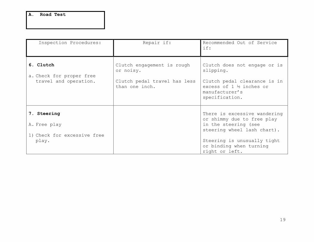
6. Clutch
a. Check for proper free travel and operation.
Clutch engagement is rough
or noisy.
Clutch pedal travel has less
than one inch.
Clutch does not engage or is
slipping.
Clutch pedal clearance is in
excess of 1 ½ inches or
manufacturer’s
specification.
7. Steering
A. Free play
1) Check for excessive free play.
There is excessive wandering
or shimmy due to free play
in the steering (see
steering wheel lash chart).
Steering is unusually tight
or binding when turning
right or left.
A. Road Test

20
Inspection Procedures: Repair if: Recommended Out of Service
if:
7. Steering
B. Wheel
1) Visually inspect the condition of the wheel.
Steering wheel plastic
cracked.
Steering wheel loose on
column.
Steering wheel non O.E.M
design.
Plastic missing so that
metal steering wheel
reinforcement is exposed.
C. Column
1) Check the column in the bus for up and down
movement, side to side
movement and proper
mounting.
Rubber boot at bulkhead (if
equipped) is torn or
missing.
Side to side movement
exceeds ¼-inch or up and
down movement exceeds 1-
inch.
Columns mount assembly
mounting (including floor
mounting plate) or fasteners
loose.
2) Check for operation of tilt and telescoping
function if equipped.
Does not tilt or telescope.
Does not latch securely in
place.
A. Road Test

21
7. Steering
Chart
Steering wheel play (lash) Measurements
Lash shall not exceed the following measurements.
Steering Wheel
Size
Play(Lash)
Manual Steering
Play (Lash)
Power Steering
16 inches or less 2 inches 4 ½ inches
18 inches 2 ¼ inches 4 ¾ inches
20 inches 2 ½ inches 5 ¼ inches
22 inches 2 ¾ inches 5 ¾ inches

22
Inspection Procedures: Repair if: Recommended Out of Service
if:
8. Transmission
a.Check for proper operation
by shifting through shift
pattern.
Does not shift easily into
all gears.
Will not shift into all
gears.
Indicates wrong gear (Touch
pad).
LED’s out and/or can’t tell
which gear the transmission
is in.
Detent is non-functional.
Knob or handle missing from
the end of shifter.
There is excessive rough up
or down shifting or hard
shifts.
Transmission will not shift
up or down through gear
range.
Transmission is slipping or
noisy.
Shift points are not within
manufacturer’s
specification.
A. Road Test
A. Road Test

23
Inspection Procedures: Repair if: Recommended Out of Service
if:
9. Backup Alarm.
Check for presence of back
up alarm (buses manufactured
starting November 1990) and
dash sticker (starting
November 1993). Check
operation of alarm by
placing transmission in
reverse (engine running) and
listening for alarm sound.
Dash sticker is not mounted
on dash in plain view of the
driver.
Dash sticker is not present
(starting November 1993).
Transmission will not shift
up or down through gear
range.
Transmission is slipping or
noisy.
Shift points are not within
manufacturer’s
specification.
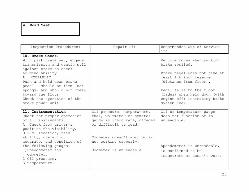
10. Brake Check.
A. AIR
1) Chock wheels if necessary and push in parking brake
knob.
Start engine.
2) Air pressure build up
from 50 to 90 psi should not
exceed 5 min. at first
engine idle.
Dash sticker is not mounted
on dash in plain view of the
driver.
Dash sticker is not present
(starting November 1993).
Brake pedal pad is missing
(if originally equipped) or
worn out. Pedal is equipped
with any “extender” block.
A. Road Test

24
A. Road Test
Inspection Procedures: Repair if: Recommended Out of Service
if:
10. Brake Check.
Compressor governor cut out
pressure should be reached
at approximately 120--psi.
Shut off engine and turn key
back on.
With brakes in the released
position, check for air
pressure leak (pressure
drop) for at least 1-minute.
Firmly depress brake pedal
and do not release. Check
for air pressure leak
(pressure drop) for at least
1-minute. Air leakage should
not exceed 3 psi per minute.
Air leaks, but rate is less
than 2 psi per minute
(brakes released) or 3 psi
per minute (with service
brakes applied).
Air pressure leaks more than
2 psi per minute, (brakes
not applied), or more than 3
psi per minute (with service
brake applied).

25
A. Road Test
Inspection Procedures: Repair if: Recommended Out of Service
if:
10. Brake Check.
Step on and off brake pedal
to decrease air pressure-
warning light and buzzer
should activate at about 60
psi.
Continue to decrease air
pressure-parking brake knob
should pop out between 20-
and 45 psi.
Restart engine, shift into
lo gear and gently pull
against brakes to make sure
they will hold.
Set hand brake
(Orschlein)-must cam over
center (adjust if
necessary).
Vehicle moves when parking
brake applied.
26
A. Road Test
Inspection Procedures: Repair if: Recommended Out of Service
if:
10. Brake Check.
With park brake set, engage
transmission and gently pull
against brake to check
holding ability.
A. HYDRAULIC Push and hold down brake
pedal – should be firm (not
spongy) and should not creep
toward the floor.
Check the operation of the
brake power unit.
Vehicle moves when parking
brake applied.
Brake pedal does not have at
least 1 ½ inch reserve
(distance from floor).
Pedal falls to the floor
(fades) when held down (with
engine off) indicating brake
system leak.
11. Instrumentation
Check for proper operation
of all instruments.
A. Check from driver’s
position the visibility,
O.E.M. location, read-
ability, operation,
accuracy, and condition of
the following gauges:
1)Speedometer and
odometer.
2 Oil pressure.
3)Temperature.
Oil pressure, temperature,
fuel, voltmeter or ammeter
gauge is inaccurate, damaged
or difficult to read.
Odometer doesn’t work or is
not working properly.
Odometer is unreadable
Oil or temperature gauge
does not function or is
unreadable.
Speedometer is unreadable,
is confirmed to be
inaccurate or doesn’t work.
27
A. Road Test
Inspection Procedures: Repair if: Recommended Out of Service
if:
11. Instrumentation
4) Fuel.
5) Voltmeter or ammeter
(voltmeter only required
starting September 1985).
6) Air pressure or vacuum.
Air pressure or vacuum
gauge(s) are inaccurate,
unreadable, or not working.
Air pressure gauge must read
within plus or minus seven
7psi. (single gauge) at 100
psi.
B. Check for presence and
operation of the following
indicators:
1) Air pressure or vacuum
gauge or warning light.
2) High beam light.
3) Left and right turn
signal and 4-way hazard.
4) Check all dash and
control panel lights for
illumination at gauges and
switches.
Not equipped with voltmeter
for bus purchased starting
September 1985
Illumination for the
following gauge or control
is inoperative:
1) Oil pressure
2) Temperature
3) Fuel
4) Voltmeter
5) Ammeter
6) Engine Shutdown
(Bowden Cable)
7) Strobe light
Illumination for the
following gauge or control
is inoperative:
1) Air pressure or vacuum. 2) High beam. 3) Left or right turn
signal or 4-way hazard.
All dash or control panel
lights are inoperative.
Shift Indicator light is
inoperative.
Any gauge missing or cannot
be read.

28
A. Road Test
Inspection Procedures: Repair if: Recommended Out of Service
if:
12. Mirrors
a. Rearview
Check all mirrors for clear
visibility.
Check exterior rearview
mirrors specifications,
condition, mounting, and
adjustment.
Any exterior rearview mirror
is broken, cracked, or loose
in frame.
Either mirror does not give
driver a clear view down to
lower outside edge of rear
tire at ground level, on
both sides to the rear.
Any bracket is broken or
mirror mounting is insecure.
Reflective surface is
deteriorated.
Any mirror does not meet
applicable specification.
b. Convex
Check convex crosswalk and
side-view mirrors for
specifications (correct
type, size, and location)
condition, mounting, and
adjustment.
Required convex mirrors are
not present.
Any mirror is cracked,
broken, or loose in frame.

29
A. Road Test
Inspection Procedures: Repair if: Recommended Out of Service
if:
c. Interior
Check interior rearview
mirror for size, condition,
and mounting.
Any portion of reflective
surface is obstructed by
stickers or other items or
is deteriorated.
Driver’s view of images in
mirror is not clear due to
distortion or other causes.
Mirror mounting is loose. 13. Heaters & Defrosters.
a. Heaters
Check for proper operation.
Inspect heater system for:
1) Heating performance and
water control valve
(interior).
2) Blower operation,
condition, and control
switches.
Not producing adequate
heat (including any
auxiliary heat)
Water control valve hard to
operate.
Heater blowers do not work on
all speeds, are noisy, or
vibrate.
Heater cores, hoses, or
valve leaks (including any
auxiliary heater).
Heater hoses are cracked,
swollen, or badly chafed.
Shielding is missing
(starting November 1980) or
does not completely cover
hoses.

30
A. Road Test
Inspection Procedures: Repair if: Recommended Out of Service if:
13. Heaters & Defrosters.
3) System leakage,
condition, and hose
shielding (shielding
required starting November
1980).
4) Condition of ductwork
and heater box.
Blower switches are damaged,
loose, or blower operates
intermittently. Heater ductwork or heater box
components are missing,
damaged, loose, or obstructed.
Any portion of heating system
within passenger area creates
sharp edges, projections, or
other hazards to passengers.
b. Defrosters
Inspect windshield defroster
system for:
1) Airflow, heat, and coverage
area.
2) Blower operation,
condition, and control
switches.
3) Condition of ductwork,
diffusers, and fresh air
control (if equipped).
Any defroster blower does not
work on low speed, is noisy,
or vibrates.
Blower switches are damaged or
loose.
Any ductwork or diffusers are
loose or damaged.
Fresh air control (if
equipped) does not function.
Airflow is not present at all
defroster outlets.
Any defroster blower does not
work on high speed.

31
A. Road Test
Inspection Procedures: Repair if: Recommended Out of Service
if:
14. Windshield Wipers.
a. Operation
Check for proper operation.
Inspect both wipers for:
1) Swept area field of view
and effectiveness of wiping.
2) Proper operation of both
wipers on high and low
speeds and condition and
mounting of switch(es) and
knob(s).
Either wiper does not
operate on low speed.
Wiper goes past perimeter of
glass.
Either wiper does not
effectively clear driver’s
field of vision.
Switch(es) mounting loose or
knob(s) missing or loose.
3) Condition and mounting of
wiper motors and linkage.
diffusers, and fresh air
control (if equipped).
Either wiper motor or
linkage is visibly damaged
or loose.

32
A. Road Test
Inspection Procedures: Repair if: Recommended Out of Service
if:
14. Windshield Wipers.
b. Park
Inspect for parked
position of wipers when
turned off (electric) or
when manually parked
(air).
Electric wipers do not
automatically return to
parked position out of
driver’s line of sight
when turned off.
Air wipers cannot be
manually parked out of
driver’s line of sight using
control switch.
c. Blades
Inspect blades for
condition, mounting, and
tension.
Poor cleaning of windshield. Either blade is damaged,
deteriorated, loose,
or does not hold proper
tension against
windshield.
15. Windshield Washers.
1) Check for proper
operation.
Washer does not operate or
is misadjusted.

33
A. Road Test
Inspection Procedures: Repair if: Recommended Out of Service
if:
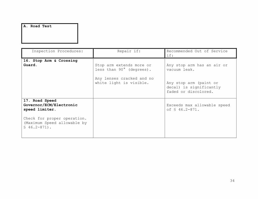
16. Stop Arm & Crossing
Guard.
a. Stop arm.
Check stop arm(s) for
specifications and
operation fully extends to
90°(degrees).
Wiring-ground strap is loose
or not properly routed and
secured.
Hinge or bushing(s) is dry
of lubrication.
Stop arm assembly or blade
mounting is loose.
Wires or ground strap(s) is
broken.
Any stop arm light does not
flash or does not flash
between 60 and 120 times per
minute.
Stop arm does not fully
extend or retracts slowly.
b. Crossing Arm.
Check for proper operation
by cycling through warning
lights, entrance door
opening.
Check front bumper mounted
student crossing arm for
operation, condition, and
mounting.
Not equipped with student
crossing arm, starting
January 1990.
Does not fully extend 90°
(degrees) from bumper.
Does not deploy when stop
arm switch is activated.
34
A. Road Test
Inspection Procedures: Repair if: Recommended Out of Service
if:
16. Stop Arm & Crossing
Guard.
Stop arm extends more or
less than 90° (degrees).
Any lenses cracked and no
white light is visible.
Any stop arm has an air or
vacuum leak.
Any stop arm (paint or
decal) is significantly
faded or discolored.
17. Road Speed
Governor/ECM/Electronic
speed limiter.
Check for proper operation.
(Maximum Speed allowable by
§ 46.2-871).
Exceeds max allowable speed
of § 46.2-871.
35
B. Body Interior
Inspection Procedures: Repair if: Recommended Out of Service
if:
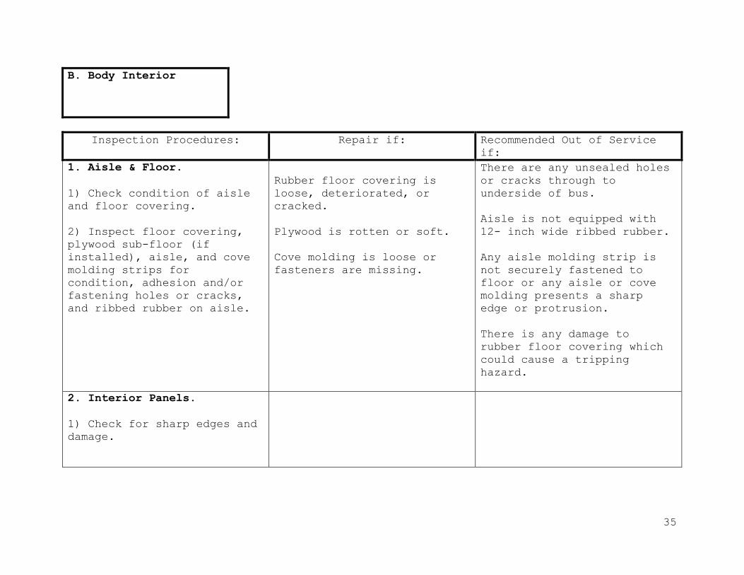
1. Aisle & Floor.
1) Check condition of aisle
and floor covering.
2) Inspect floor covering,
plywood sub-floor (if
installed), aisle, and cove
molding strips for
condition, adhesion and/or
fastening holes or cracks,
and ribbed rubber on aisle.
Rubber floor covering is
loose, deteriorated, or
cracked.
Plywood is rotten or soft.
Cove molding is loose or
fasteners are missing.
There are any unsealed holes
or cracks through to
underside of bus.
Aisle is not equipped with
12- inch wide ribbed rubber.
Any aisle molding strip is
not securely fastened to
floor or any aisle or cove
molding presents a sharp
edge or protrusion.
There is any damage to
rubber floor covering which
could cause a tripping
hazard.
2. Interior Panels.
1) Check for sharp edges and
damage.

36
B. Body Interior
Inspection Procedures: Repair if: Recommended Out of Service
if:
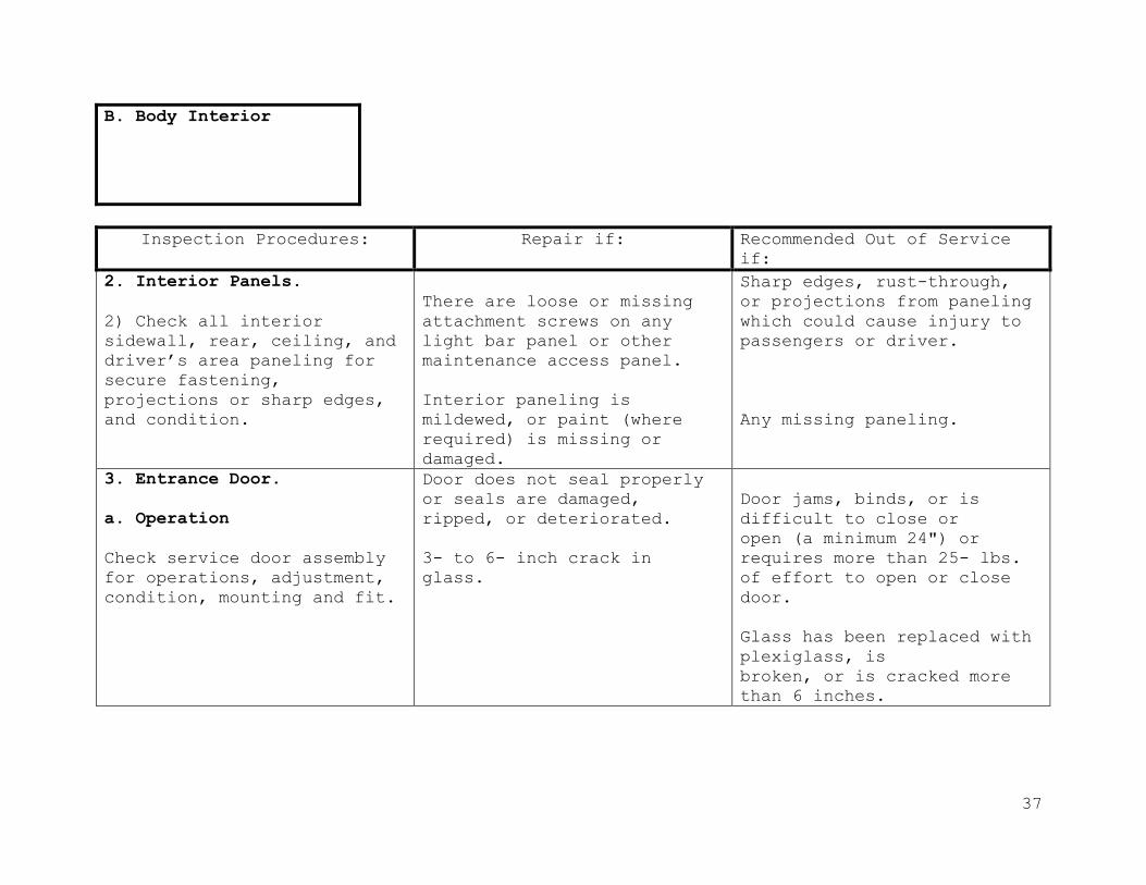
2. Interior Panels.
2) Check all interior
sidewall, rear, ceiling, and
driver’s area paneling for
secure fastening,
projections or sharp edges,
and condition.
There are loose or missing
attachment screws on any
light bar panel or other
maintenance access panel.
Interior paneling is
mildewed, or paint (where
required) is missing or
damaged.
Sharp edges, rust-through,
or projections from paneling
which could cause injury to
passengers or driver.
Any missing paneling.
3. Entrance Door.
a. Operation
Check service door assembly
for operations, adjustment,
condition, mounting and fit.
Door does not seal properly
or seals are damaged,
ripped, or deteriorated.
3- to 6- inch crack in
glass.
Door jams, binds, or is
difficult to close or
open (a minimum 24") or
requires more than 25- lbs.
of effort to open or close
door.
Glass has been replaced with
plexiglass, is
broken, or is cracked more
than 6 inches.
37
B. Body Interior
Inspection Procedures: Repair if: Recommended Out of Service
if:
2. Interior Panels.
2) Check all interior
sidewall, rear, ceiling, and
driver’s area paneling for
secure fastening,
projections or sharp edges,
and condition.
There are loose or missing
attachment screws on any
light bar panel or other
maintenance access panel.
Interior paneling is
mildewed, or paint (where
required) is missing or
damaged.
Sharp edges, rust-through,
or projections from paneling
which could cause injury to
passengers or driver.
Any missing paneling.
3. Entrance Door.
a. Operation
Check service door assembly
for operations, adjustment,
condition, mounting and fit.
Door does not seal properly
or seals are damaged,
ripped, or deteriorated.
3- to 6- inch crack in
glass.
Door jams, binds, or is
difficult to close or
open (a minimum 24") or
requires more than 25- lbs.
of effort to open or close
door.
Glass has been replaced with
plexiglass, is
broken, or is cracked more
than 6 inches.

38
B. Body Interior
Inspection Procedures: Repair if: Recommended Out of Service
if:
3. Entrance Door.
Door glass is fogged more
than one 1-inch in from
border, or visibility
through glass is poor.
Door is equipped with any
hasp or lock except factory
approved system.
Door assembly is damaged, or
mounting is loose.
Door seals are not present.
b. Control
1) Check manual service door
control and rod assembly for
over-center or latching
device condition, mounting
and operation.
Control, rod hardware, or
mounting is loose.
Door control doesn’t operate
freely.
Door will not open or close
completely.
Manual control will not lock
over-center, or
latching mechanism is
inoperative.
Door control requires
excessive force to operate.
39
B. Body Interior
Inspection Procedures: Repair if: Recommended Out of Service
if:
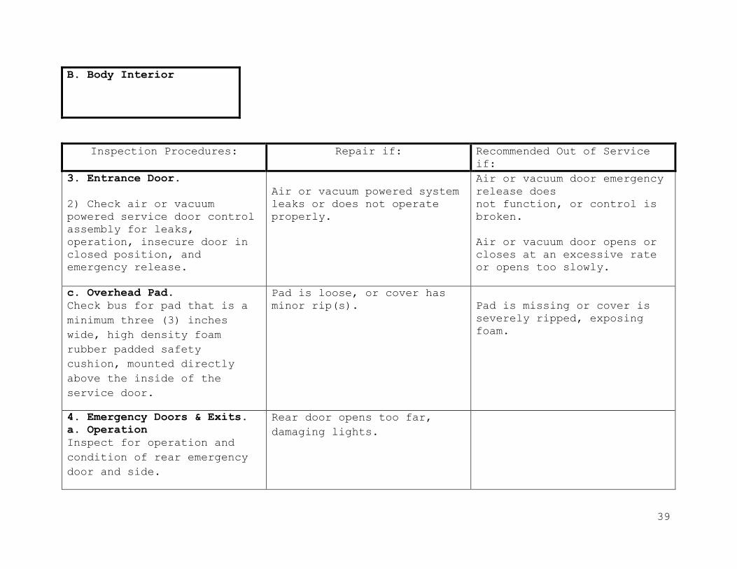
3. Entrance Door.
2) Check air or vacuum
powered service door control
assembly for leaks,
operation, insecure door in
closed position, and
emergency release.
Air or vacuum powered system
leaks or does not operate
properly.
Air or vacuum door emergency
release does
not function, or control is
broken.
Air or vacuum door opens or
closes at an excessive rate
or opens too slowly.
c. Overhead Pad.
Check bus for pad that is a
minimum three (3) inches
wide, high density foam
rubber padded safety
cushion, mounted directly
above the inside of the
service door.
Pad is loose, or cover has
minor rip(s).
Pad is missing or cover is
severely ripped, exposing
foam.
4. Emergency Doors & Exits.
a. Operation
Inspect for operation and
condition of rear emergency
door and side.
Rear door opens too far,
damaging lights.

40
B. Body Interior
Inspection Procedures: Repair if: Recommended Out of Service
if:
4. Emergency Doors & Exits.
(buses built after November
1993), door latch, door hold
open feature, door seal,
emergency windows, and
emergency exits/ventilator
(roof hatches).
Any exit handle, latch, or
mounting hardware
is loose or missing.
Mounting of guard for inside
rear door handle is loose.
Hold open device (if
equipped) is non-
operational, bent, damaged
or loose.
Any emergency exit door,
window, or hatch latch does
not operate smoothly and
easily when closing or
opening the door, window, or
hatch.
Inside door handle is not
equipped with a guard (rear
door only).
Any emergency exit does not
open and close from the
inside and outside easily.
Any emergency door or exit
is equipped with any type of
a hasp, lock, or any other
locking device, except for
an O.E.M. interlock system.
Weatherstrip does not seal.
Door does not open at least
90° (degrees).
41
B. Body Interior
Inspection Procedures: Repair if: Recommended Out of Service
if:
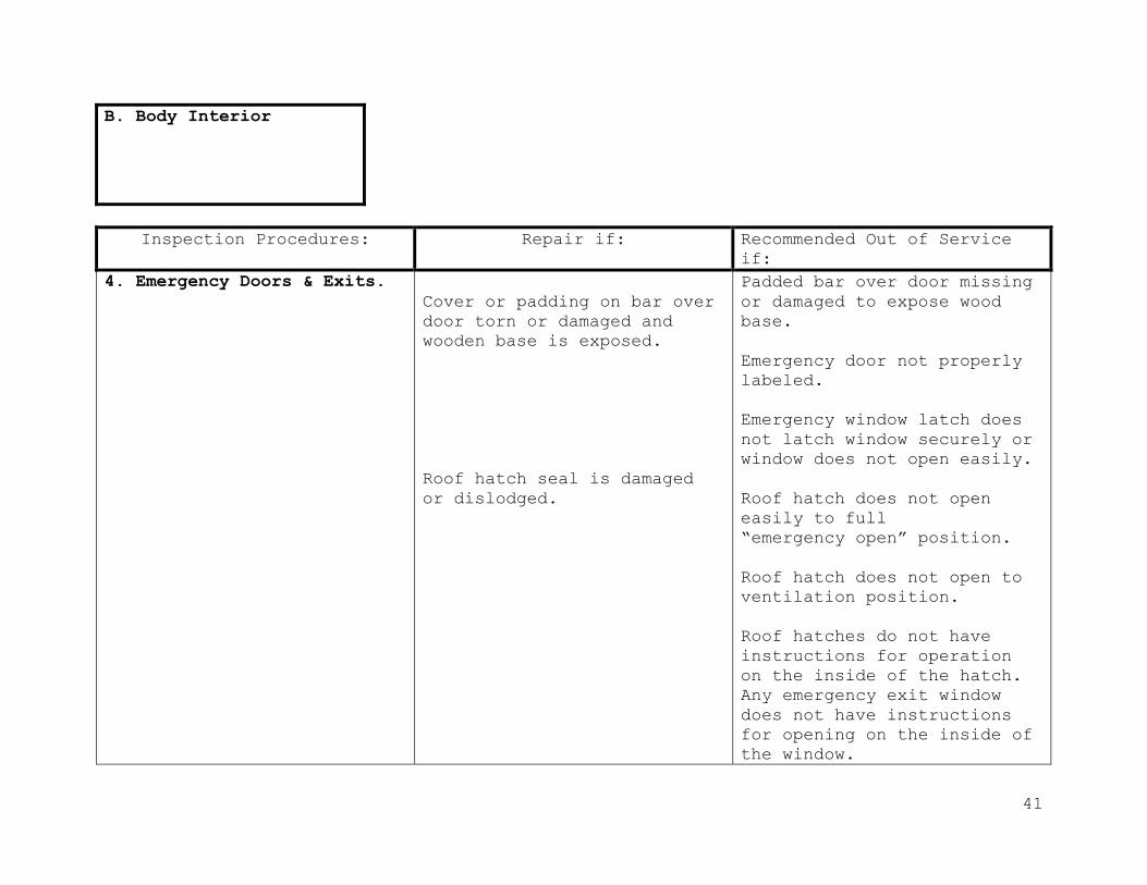
4. Emergency Doors & Exits.
Cover or padding on bar over
door torn or damaged and
wooden base is exposed.
Roof hatch seal is damaged
or dislodged.
Padded bar over door missing
or damaged to expose wood
base.
Emergency door not properly
labeled.
Emergency window latch does
not latch window securely or
window does not open easily.
Roof hatch does not open
easily to full
“emergency open” position.
Roof hatch does not open to
ventilation position.
Roof hatches do not have
instructions for operation
on the inside of the hatch.
Any emergency exit window
does not have instructions
for opening on the inside of
the window.

42
B. Body Interior
Inspection Procedures: Repair if: Recommended Out of Service
if:
b. Buzzers
Check operation of buzzers
for emergency door(s),
roof hatch(es) and
emergency exit windows.
Buzzer gives false alarms.
Buzzer system for emergency
door(s), roof hatch(es) or
any exit window does not
function or is not audible
at driver’s location.
5. Emergency Equipment.
a. Fire Extinguisher.
Check for presence of fire
extinguisher and for the
following:
1) Pressure: check gauge.
2) Tag (Inspection Date):
check for presence of
inspection sticker or tag
and inspection date.
No fire extinguisher on the
bus.
Labeling is not legible to
determine size and types.
Pressure above or below
green zone.

43
Inspection Procedures: Repair if: Recommended Out of Service
if:
5. Emergency Equipment.
3) Mounting: check for
accessibility and
secure mounting.
4) Rating: check for proper
UL.
5) Nozzle: check for loose
or damaged parts.
6) Safety Pin: check for
presence of safety pin and
tamper proof seal.
Bracket mount to panel is
loose.
Fire extinguisher is not
accessible to the driver or
not secured in the mounting
bracket.
Rating is less than:
1990 and prior -2.5-lb.
10BC.
1992 and later – 5.0-lb. 2A,
10BC or greater.
Nozzle or hose missing,
obstructed, or excessive
damage to any parts of the
extinguisher.
Safety pin missing or seal
broken.
Tamper proof seal not of
approved type.
B. Body Interior

44
Inspection Procedures: Repair if: Recommended Out of Service
if:
b. First Aid Kit & Body
Fluid Kits.
1) Check the kits mounting
and contents.
2) Mounting: Check
accessibility and mounting
of kits. Should be placed in
the driver’s area in such a
manner that they can be
easily detached and made
portable.
Either kit not labeled.
Tamper proof seal broken or
missing. Must check contents
if seals broken or missing.
Loose mounting or bracket.
Required contents are
missing or incomplete.
Either kit not present.
Either kit is not moisture
and dust proof, will not
seal, will not stay latched,
or contents inaccessible due
to the condition of the
container.
Either kit not mounted or
inaccessible.
Either kit’s content not
individually sealed.
B. Body Interior

45
Inspection Procedures: Repair if: Recommended Out of Service
if:
5. Emergency Equipment.
c. Reflectors.
1) Check reflective triangles
and mounting.
2) Check quantity: 3-each
required.
3) Check accessibility,
mounting and condition of
box.
Storage box is broken or will
not remain latched
Bus manufactured after 1992
is not equipped with a self-
standing, triangular, 17”
tall reflectors. Any of the
reflectors are broken,
deformed or unusable.
Box is not accessible or not
securely mounted.
d. Web Belt Cutter.
1) Check for the presence of
a durable webbing cutter
mounted in the driver’s
compartment and within easy
reach of a seated driver.
Webbing cutter is not
securely mounted in the
driver’s compartment and
within easy reach of a seated
driver.
Buses manufactured before
September 2007 with
wheelchair positions and
restraining devices and no
durable webbing cutter is
present.
Buses manufactured after 2007
and no durable webbing cutter
present.
B. Body Interior
46
Inspection Procedures: Repair if: Recommended Out of Service
if:
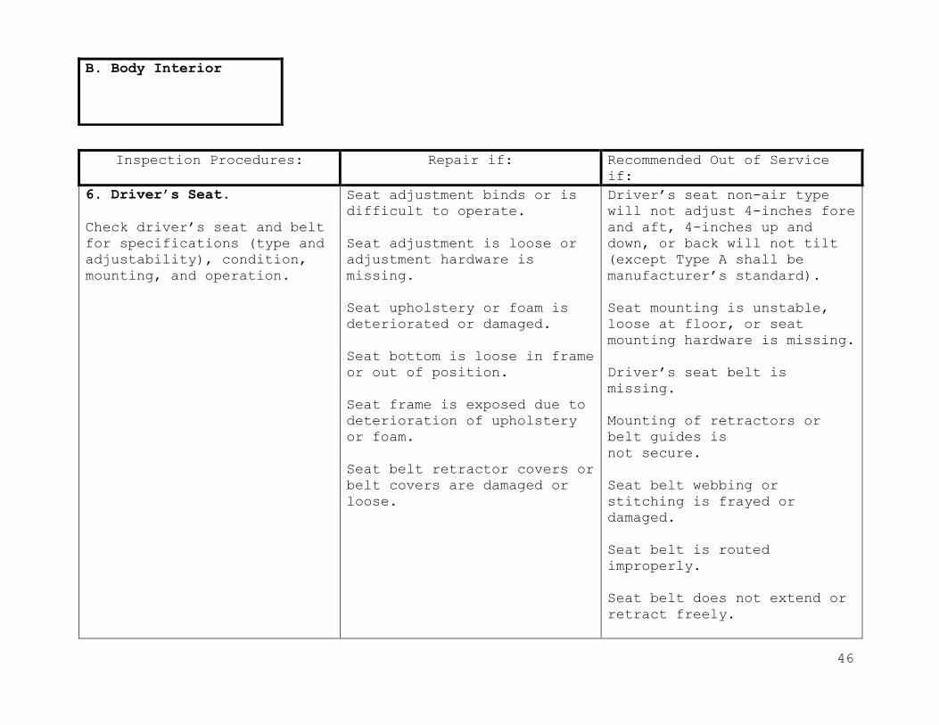
6. Driver’s Seat.
Check driver’s seat and belt
for specifications (type and
adjustability), condition,
mounting, and operation.
Seat adjustment binds or is
difficult to operate.
Seat adjustment is loose or
adjustment hardware is
missing.
Seat upholstery or foam is
deteriorated or damaged.
Seat bottom is loose in frame
or out of position.
Seat frame is exposed due to
deterioration of upholstery
or foam.
Seat belt retractor covers or
belt covers are damaged or
loose.
Driver’s seat non-air type
will not adjust 4-inches fore
and aft, 4-inches up and
down, or back will not tilt
(except Type A shall be
manufacturer’s standard).
Seat mounting is unstable,
loose at floor, or seat
mounting hardware is missing.
Driver’s seat belt is
missing.
Mounting of retractors or
belt guides is
not secure.
Seat belt webbing or
stitching is frayed or
damaged.
Seat belt is routed
improperly.
Seat belt does not extend or
retract freely.
B. Body Interior
47
Inspection Procedures: Repair if: Recommended Out of Service
if:
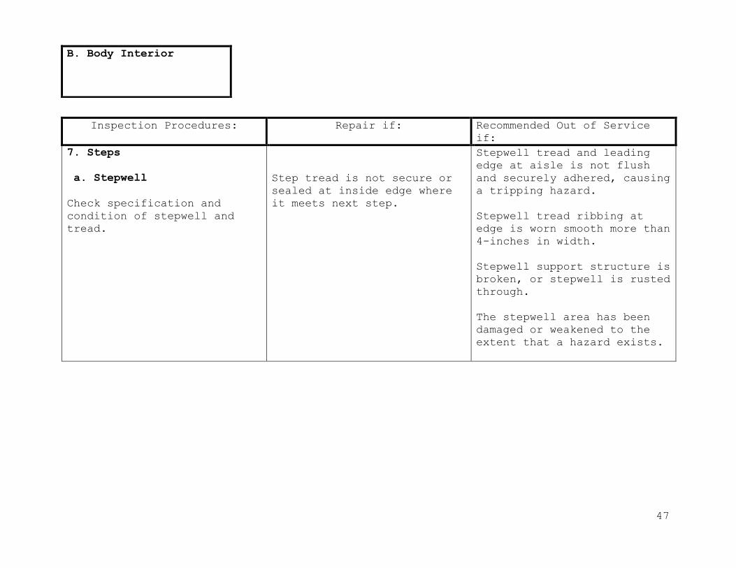
7. Steps
a. Stepwell
Check specification and
condition of stepwell and
tread.
Step tread is not secure or
sealed at inside edge where
it meets next step.
Stepwell tread and leading
edge at aisle is not flush
and securely adhered, causing
a tripping hazard.
Stepwell tread ribbing at
edge is worn smooth more than
4-inches in width.
Stepwell support structure is
broken, or stepwell is rusted
through.
The stepwell area has been
damaged or weakened to the
extent that a hazard exists.
B. Body Interior
48
Inspection Procedures: Repair if: Recommended Out of Service
if:
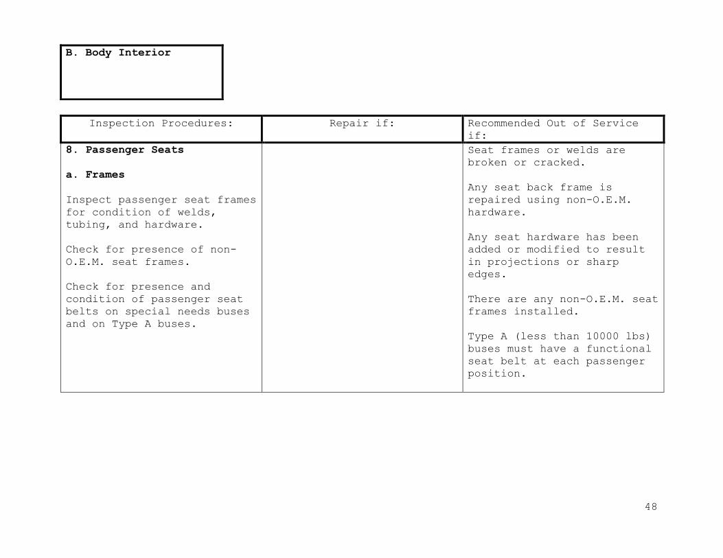
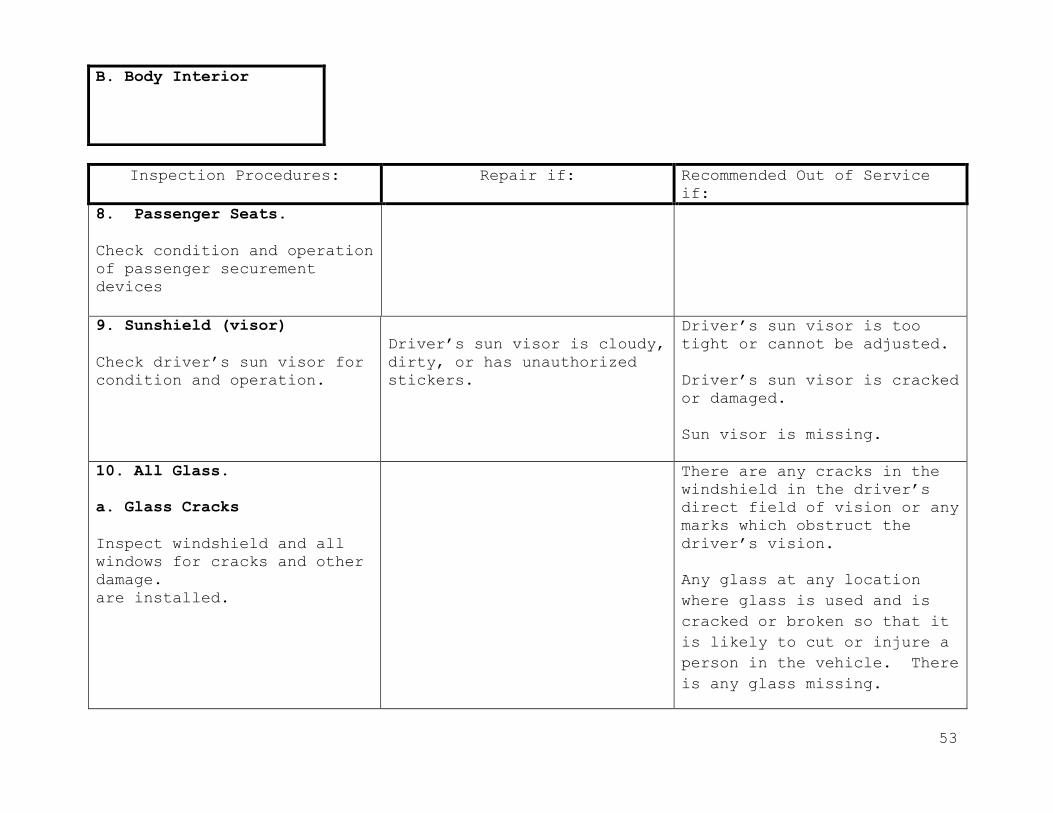
8. Passenger Seats
a. Frames
Inspect passenger seat frames
for condition of welds,
tubing, and hardware.
Check for presence of non-
O.E.M. seat frames.
Check for presence and
condition of passenger seat
belts on special needs buses
and on Type A buses.
Seat frames or welds are
broken or cracked.
Any seat back frame is
repaired using non-O.E.M.
hardware.
Any seat hardware has been
added or modified to result
in projections or sharp
edges.
There are any non-O.E.M. seat
frames installed.
Type A (less than 10000 lbs)
buses must have a functional
seat belt at each passenger
position.
B. Body Interior
49
Inspection Procedures: Repair if: Recommended Out of Service
if:
8. Passenger Seats
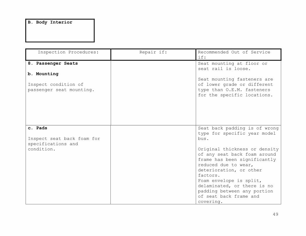
b. Mounting
Inspect condition of
passenger seat mounting.
Seat mounting at floor or
seat rail is loose.
Seat mounting fasteners are
of lower grade or different
type than O.E.M. fasteners
for the specific locations.
c. Pads
Inspect seat back foam for
specifications and
condition.
Seat back padding is of wrong
type for specific year model
bus.
Original thickness or density
of any seat back foam around
frame has been significantly
reduced due to wear,
deterioration, or other
factors.
Foam envelope is split,
delaminated, or there is no
padding between any portion
of seat back frame and
covering.
B. Body Interior

50
Inspection Procedures: Repair if: Recommended Out of Service
if:
8. Passenger Seats.
d. Cuts/Upholstery
Inspect seat upholstery for
condition and specifications.
Seat upholstery is cut, torn,
or ripped less than 6-inches.
Foam envelope is split,
delaminated, or there is no
padding between any portion
of seat back frame and
covering.
Seat upholstery is cut, torn,
or ripped more than 6-inches.
Any portion of seat back or
bottom upholstery is missing
or repaired improperly,
exposing foam.
e. Bottoms
Inspect seat bottoms for
securement.
Any seat bottom is not
securely anchored to seat
frame.
Any seat bottom has a
protruding edge, or plywood
is broken.
Any seat bottom padding or
cushion has significant
deterioration or damage.
B. Body Interior

51
Inspection Procedures: Repair if: Recommended Out of Service if:
8. Passenger Seats.
Inspect flip-up type seat
bottom at side emergency door
(if equipped) for proper
operation. Must have clear
access to emergency door with
a minimum aisle width of 12”
(inches) between seats.
Seat upholstery is cut, torn,
or ripped less than 6-inches.
Foam envelope is split,
delaminated, or there is no
padding between any portion of
seat back frame and covering.
Seat upholstery is cut, torn,
or ripped more than 6-inches.
Any portion of seat back or
bottom upholstery is missing
or repaired improperly,
exposing foam.
f. Modesty Panels and
Stanchions.
Inspect modesty panels
stanchions, and courtesy
panels for condition,
specifications, mounting, and
padding (as required).
.
Stanchion or modesty panel
mounting is loose.
No padded safety barrier in
front of any passenger seat
that does not have another
seat in front of it exception:
pre-1990 Type A Bus).
Crash barrier foam envelope is
split or delaminated, or there
is no padding between any
portion of barrier frame and
covering. Original thickness
or density of crash barrier
foam around frame has been
significantly reduced due to
wear, deterioration, or other
factors.
B. Body Interior

52
Inspection Procedures: Repair if: Recommended Out of Service
if:
Any portion of crash barrier
upholstery is missing or not
repaired properly, exposing
foam. Crash barrier
upholstery is cut, torn, or
ripped.
g. Optional Infant Seating
(if equipped).
Check condition and
operation of system.
Seat does not operate or
function properly according
to manufacturer’s operational
procedures.
h. Passenger Securement
Devices (if equipped).
All buses equipped with 2-
or 3-point passenger
securement systems shall be
equipped with FMVSS 210
compliant seat frames and
FMVSS 209 compliant belt
assemblies in all passenger
seating positions where
passenger securement systems
are installed.
Belts knotted, misrouted,
retractor covers damaged or
loose.
Will not latch or stay
latched, wrong type,
missing, broken, mismatched,
improperly installed, or
frayed.
B. Body Interior
53
Inspection Procedures: Repair if: Recommended Out of Service
if:
8. Passenger Seats.
Check condition and operation
of passenger securement
devices
9. Sunshield (visor)
Check driver’s sun visor for
condition and operation.
Driver’s sun visor is cloudy,
dirty, or has unauthorized
stickers.
Driver’s sun visor is too
tight or cannot be adjusted.
Driver’s sun visor is cracked
or damaged.
Sun visor is missing.
10. All Glass.
a. Glass Cracks
Inspect windshield and all
windows for cracks and other
damage.
are installed.
There are any cracks in the
windshield in the driver’s
direct field of vision or any
marks which obstruct the
driver’s vision.
Any glass at any location
where glass is used and is
cracked or broken so that it
is likely to cut or injure a
person in the vehicle. There
is any glass missing.
B. Body Interior

54
Inspection Procedures: Repair if: Recommended Out of Service if:
10. All Glass. Windshield glass, on the
driver’s side, has any scratch
more than ¼-inch in width and
6-inches within the area
covered by the windshield wiper
blade, excluding the three
inches above the bottom of the
windshield. A wind-shield wiper
that remains parked within the
driver’s side windshield wiper
area.
There is a pit, chip, or star
crack larger than 1-1/2 inches
in diameter at any location in
the windshield above the three-
inch line at the bottom.
At any location in the
windshield above the three-inch
line at the bottom (as measured
from the junction of the dash
board and the windshield) there
is more than one crack from the
same point if at least one of
the cracks is more than 1-1/2
inches in length. There is any
crack that weakens the
windshield so that one piece
may be moved in relation to the
other.
B. Body Interior
55
Inspection Procedures: Repair if: Recommended Out of Service
if:
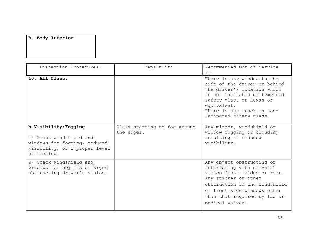
10. All Glass. There is any window to the
side of the driver or behind
the driver’s location which
is not laminated or tempered
safety glass or Lexan or
equivalent.
There is any crack in non-
laminated safety glass.
b.Visibility/Fogging
1) Check windshield and
windows for fogging, reduced
visibility, or improper level
of tinting.
Glass starting to fog around
the edges.
Any mirror, windshield or
window fogging or clouding
resulting in reduced
visibility.
2) Check windshield and
windows for objects or signs
obstructing driver’s vision.
Any object obstructing or
interfering with drivers’
vision front, sides or rear.
Any sticker or other
obstruction in the windshield
or front side windows other
than that required by law or
medical waiver.
B. Body Interior
56
Inspection Procedures: Repair if: Recommended Out of Service
if:
10. All Glass.
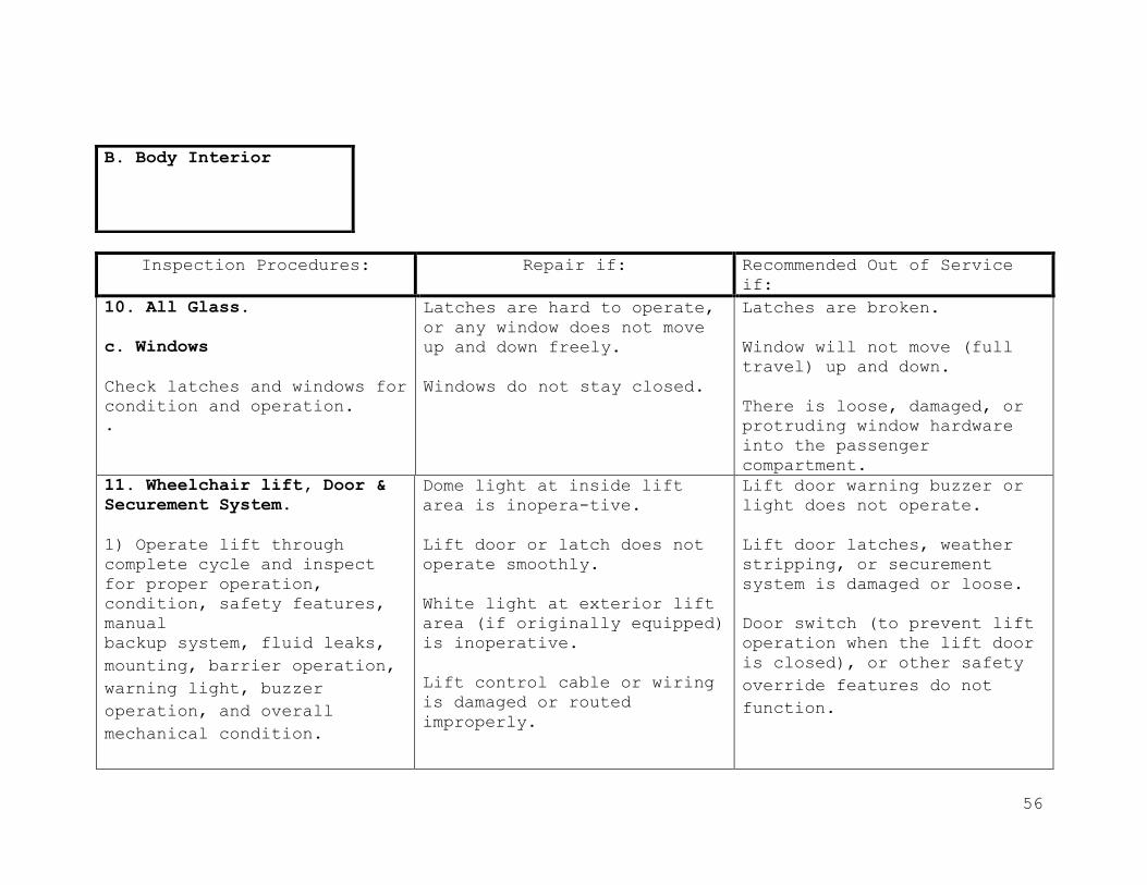
c. Windows
Check latches and windows for
condition and operation.
.
Latches are hard to operate,
or any window does not move
up and down freely.
Windows do not stay closed.
Latches are broken.
Window will not move (full
travel) up and down.
There is loose, damaged, or
protruding window hardware
into the passenger
compartment.
11. Wheelchair lift, Door &
Securement System.
1) Operate lift through
complete cycle and inspect
for proper operation,
condition, safety features,
manual
backup system, fluid leaks,
mounting, barrier operation,
warning light, buzzer
operation, and overall
mechanical condition.
Dome light at inside lift
area is inopera-tive.
Lift door or latch does not
operate smoothly.
White light at exterior lift
area (if originally equipped)
is inoperative.
Lift control cable or wiring
is damaged or routed
improperly.
Lift door warning buzzer or
light does not operate.
Lift door latches, weather
stripping, or securement
system is damaged or loose.
Door switch (to prevent lift
operation when the lift door
is closed), or other safety
override features do not
function.
B. Body Interior
57
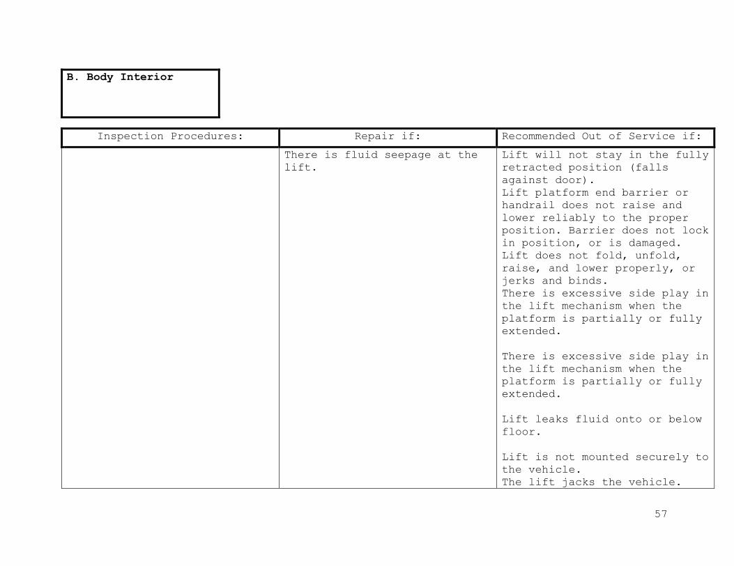
Inspection Procedures: Repair if: Recommended Out of Service if:
There is fluid seepage at the
lift.
Lift will not stay in the fully
retracted position (falls
against door).
Lift platform end barrier or
handrail does not raise and
lower reliably to the proper
position. Barrier does not lock
in position, or is damaged.
Lift does not fold, unfold,
raise, and lower properly, or
jerks and binds.
There is excessive side play in
the lift mechanism when the
platform is partially or fully
extended.
There is excessive side play in
the lift mechanism when the
platform is partially or fully
extended.
Lift leaks fluid onto or below
floor.
Lift is not mounted securely to
the vehicle.
The lift jacks the vehicle.
B. Body Interior

58
Inspection Procedures: Repair if: Recommended Out of Service
if:
11. Wheelchair Lift, Door &
Securement System.
Any part of the lift
mechanism or hardware is
damaged, missing, or not
secure, including cams,
clips, pins, rollers, and
platform fasteners.
Manual backup system does not
function properly.
2) Inspect wheelchair and
occupant securement (tie-
down) system for condition,
mounting, proper type, and
location.
Track is filled with dirt.
Wheelchair tie-down track or
fasteners are loose or
broken.
Wheelchair or occupant
securement straps are broken,
frayed, or will not operate.
Securement systems for buses
built after 1989 is not
forward facing wheelchair and
occupant securement system
meeting Virginia
specifications.
Wheelchair or occupant
securement track is mounted
using lag bolts or sheet
metal screws.
B. Body Interior

59
Inspection Procedures: Repair if: Recommended Out of Service
if:
12. Radio & Cameras (if
equipped).
Inspect cameras, radio and
antenna for condition,
mounting and location,
routing of wiring, and
perform function check.
Radio will not transmit or
receive.
Mountings are loose.
Driver has to move out of the
normal driving position to
operate communication
controls.
Wiring or connectors are un-
insulated, installed
improperly, misrouted, or
unsecured so that it could
cause a short.
B. Body Interior
60
Inspection Procedures: Repair if: Recommended Out of Service
if:
13. Interior wiring.
Inspect visible wiring for
mounting, condition, chafing
or abrasion, corrosion, loose
connectors, or improper
repairs.
Wiring or connectors are
unsecured, corroded, or
improperly routed.
Any wire or connector is cut
or severely chafed, or
conductor is exposed or
routed against a sharp edge,
or there Is interference with
driver’s controls. Any
connection of any connector
is not secure.
14. All Openings.
Check that gear shifter
(floor) boot is intact and
not damaged.
Firewall Seals:
Inspect firewall for any
cracks, unsealed openings,
and sound insulation
material.
Inspect firewall for any
cracks, unsealed openings,
and sound insulation
material.
Loose boot.
Sound deadening /insulation
package is unsecured or
deteriorated.
Boot is torn, damaged,
missing, or not attached to
floor.
There is any open hole or
unsealed area in the
firewall.
B. Body Interior

61
Inspection Procedures: Repair if: Recommended Out of Service
if:
15. Storage Compartments.
Check latch assembly for
proper operation.
Latch does not operate
properly.
Remove any trash, cans, and
bottles.
16. Posters & Stickers.
Inspect for posters or
stickers that are not
approved.
There is graffiti or
unauthorized stickers on
interior panels.
17. Loose Objects &
Cleanliness.
a) Loose Objects:
Check to see that all
objects within the bus are
secured.
Loose objects such as
trashcans, oil cans, or
other loose items are present
which are not secured in
a glove box or other secured
container.
B. Body Interior

62
Inspection Procedures: Repair if: Recommended Out of Service
if:
17. Loose Objects &
Cleanliness.
b) Cleanliness
Inspect interior for
cleanliness.
Bus is dirty.
Any aerosol can(s) or other
container(s) of liquid(s) of
flammable or volatile
chemical are on the bus.
Any aerosol or non-aerosol
chemical container present
that is not labeled.
Any carpeting or non-O.E.M
floor mats.
Bus dirty and
unsafe/unsanitary to operate
and presents a potential
health hazard.
18.Handrails
Check for presence and secure
mounting of entrance
handrail(s).
Entrance handrail(s) is
missing or not securely
mounted.
Handrail and/or any hardware
missing damaged or have
unauthorized modifications
B. Body Interior
63
Inspection Procedures: Repair if: Recommended Out of Service
if:
18. Handrails
Check handrail(s) for
required modification(s) (if
equipped). If no required
modification is present,
perform a NHTSA string and
nut test.
Handrail(s) fails NHTSA
string and nut test.
B. Body Interior

64
Inspection Procedures: Repair if: Recommended Out of Service
if:
1. Body Damage.
Check body exterior for
accident damage, scratches,
dents, etc.
Body has small dents,
scratches, etc.
Body has small rust spots or
water leaks.
Any body part is damaged or
dislocated creating a
protrusion or sharp edge.
Body panels, rivets, or other
components are damaged or
corroded to the point where
joint strength or body
structural integrity is
compromised.
2. Stirrup Steps.
Check for condition and
mounting of stirrup steps and
grab handles.
Any stirrup step loose or
missing.
Any stirrup step or grab
handle is broken.
3. License Plates.
Inspect for damage, secure
mounting and visibility.
Plates damaged, loose or
visibility blocked by
crossing control arm.
Plates missing.
C. Exterior

65
Inspection Procedures: Repair if: Recommended Out of Service
if:
4. Tow Hooks.
Inspect for damage and secure
mounting.
Damaged or missing tow hooks
(if equipped)
5. Bumpers
Check bumpers for mounting,
condition, color, and body
seal (rear bumper).
Bumper is not black.
Bumper is equipped with any
unauthorized stickers or
decals.
Bumper is significantly bent
or has protruding metal.
Bumper mounting system has
cracked, broken, or bent
brackets, braces, welds, or
missing or loose fasteners.
Bumper is cracked, torn or
broken.
Bumper is not O.E.M or
approved type.
C. Exterior
66
Inspection Procedures: Repair if: Recommended Out of Service
if:
6. Tires and Wheels.
a) Tread Depth
Inspect and measure all tires
for tread depth.
Measured tread depth of
either front tire is less
than 4/32-inch or less when
measured at any tread point
at any point on a major tread
groove. Measurement shall not
be taken at a wear bar.
Measurement shall be taken at
the most worn major tread
groove of the tire.
Measured tread depth of
either rear tire is less than
2/32 inch when measured in
two adjacent tread grooves
where tread is thinnest.
Any front tire is recapped or
re-grooved type tire.
A tire is regrooved and not
marked “regroovable”.
There is evidence that any
tire has been re-grooved
using a procedure not
approved by tire manufacturer
or dealer.
C. Exterior

67
Inspection Procedures: Repair if: Recommended Out of Service
if:
6. Tires and Wheels.
b) Pressure
With tire cold, check
pressures of all tires.
Pressure not within range
marked on the sidewall.
Pressure in the dual tires
not within 10 percent of each
other.
Any tire flat or has audible
air leak.
c) Damage
Inspect for damage to wheels
and tires.
There is foreign material in
the tire tread, which could
cause damage or loss of air
pressure.
There are any cuts, abrasion,
or other damage to tire
sidewall resulting in exposed
or damaged cord.
There is any evidence of
separation, bulges (other
than normal manufacturer
bulge), or other damage
within the carcass of the
tire. There are any cracks
that run around the bead or
sidewall of the tire.
On retread tire there is any
separation of the tire tread
from the tire carcass, which
could result in tire or tread
failure.
C. Exterior

68
Inspection Procedures: Repair if: Recommended Out of Service
if:
6. Tires & Wheels. Any valve cap is missing.
There are minor dents or
bends in a rim.
Any valve stem is damaged or
not-aligned so that tire
cannot be filled with air.
There are any cracks or
breaks at the lug holes or
any other part of a rim or
cast spokes.
d) Matching
Inspect for matching of tire
construction, design, size,
and load rating on each axle.
There is mismatching of inner
and outer dual tire diameter
greater than 3/8-inch.
There is any tire marked for
other than highway use. Any
tire is not of proper type,
size, and minimum load
rating.
Radial and bias ply tires are
intermixed on
the same axle.
C. Exterior
69
Inspection Procedures: Repair if: Recommended Out of Service
if:
6. Tires & Wheels.
e) Alignment
Inspect tires for evidence of
proper alignment.
Any tire is feather-edged,
cupped, or has uneven tread
wear.
Lateral run out of any
tire/rim assembly exceeds ¼-
inch.
Tires/wheels are grossly
misaligned, affecting
steering control.
f) Wheel Hardware.
Inspect for presence, type,
condition, and securement of
all wheel hardware.
Check for proper spacing of
rear dual wheels and tires
(proper spacer width).
Stud holes are elongated.
Any wheel nut, stud, bolts,
clamp or other fasteners are
loose, broken, cracked,
stripped, missing, damaged or
otherwise ineffective.
Any welded repair on wheels
mounted on the steering axle.
C. Exterior

70
Inspection Procedures: Repair if: Recommended Out of Service
if:
7. Lights and Signals
Check both headlights for
brightness, operation,
condition of sealed beams,
and visible misaiming. Check high beam indicator operation
and headlight switch.
Left and right sealed beams
are of different type
(halogen vs. conventional).
Either sealed beam does not
light on low and high.
Any sealed beam lens is
fogged, cracked, or light is
dim.
Dimmer switch sticks, is hard
to operate, or doesn’t
function.
Headlight switch is damaged,
not securely mounted, or knob
is missing.
Lights go out after being on
a short time, or operation is
intermittent.
Upon visible inspection,
there is any obvious
misaiming of headlights.
C. Exterior

71
Inspection Procedures: Repair if: Recommended Out of Service
if:
7. Lights & Signals
a) Turn Signals
Check turn signals (including
bulbs and lenses) for
operation, condition, and
specifications.
Any front, rear, or side-
mounted turn signal lens is
cracked.
Turn signal does not properly
indicate right or left
signal.
Turn signal does not cancel
or return to neutral
position.
Lens has a piece broken from
it. The lens may have one or
more cracks provided an off –
color light does not project
through the cracks(s). Taping
or gluing cracks or pieces is
not allowed.
Any front or side mounted
turn signal does not flash or
dim.
Turn signal does not flash
between 60- to 120-times per
minute.
Turn signal does not initiate
turn signals or will not
maintain set position.
Any turn signal lens has
darkened, faded, or is dirty,
significantly affecting
visibility or color of the
light.
b) Turn Signal
Check 4-way hazard lights for
operation and condition.
Any lens is cracked or dirty.
Either indicator fails to
function properly.
Any 4-way hazard light fails
to function.
Hazard lights do not flash
between 60- to 120-times per
minute.
C. Exterior

72
Inspection Procedures: Repair if: Recommended Out of Service if:
7. Lights & Signals
Hazard warning lamps do not
flash simultaneously.
Switch does not function or
will not maintain set position
with steering wheel in the
straight-ahead position.
Off-colored light projects
through crack in lens.
c) Side Marker.
Check side marker lights for
operation and condition.
Any side marker light fails to
function, is cracked or damaged.
d) Brake Lights
Check brake lights and
lens(es) for operation,
condition, and specifications.
One brake light on either or
both sides fails to function
(4 brake light system only).
Half or more of the O.E.M
installed brake lights fail to
function when the brake pedal
is depressed (i.e. 1- of 2-
brake light system; 2- of 4-
brake light system, or more).
For buses with only one brake
light per side, either brake
light fails to function.
C. Exterior

73
Inspection Procedures: Repair if: Recommended Out of Service if:
7. Lights & Signals
Any brake light lens cracked.
After brake pedal is released,
brake light switch sticks, or
lights stay on.
Any brake light lens is
damaged and white light is
visible.
Any brake light lens is not
red or is not proper type
meeting SAE specification.
Any brake light lens has
darkened, faded, or is dirty,
significantly affecting the
visibility or color of the
light.
e) Tail Lights. One (1) tail light on either
or both sides fails to
function (4-tail light system
only).
Any lens cracked and white
light not visible.
Half or more of the O.E.M.
installed tail lights fail to
function when the headlight
switch is in either the park
or headlight position. (i.e. 2
of 4, 1 of 2 or more)
Any tail light lens is damaged
and white light is visible.
Any tail light lens is not red
or is not proper type meeting
SAE specifications.
C. Exterior
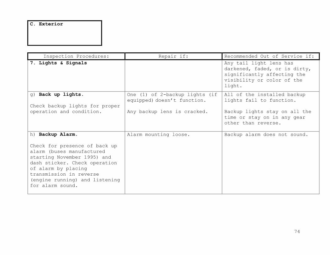
74
Inspection Procedures: Repair if: Recommended Out of Service if:
7. Lights & Signals
Any tail light lens has
darkened, faded, or is dirty,
significantly affecting the
visibility or color of the
light.
g) Back up lights.
Check backup lights for proper
operation and condition.
One (1) of 2-backup lights (if
equipped) doesn’t function.
Any backup lens is cracked.
All of the installed backup
lights fail to function.
Backup lights stay on all the
time or stay on in any gear
other than reverse.
h) Backup Alarm.
Check for presence of back up
alarm (buses manufactured
starting November 1995) and
dash sticker. Check operation
of alarm by placing
transmission in reverse
(engine running) and listening
for alarm sound.
Alarm mounting loose.
Backup alarm does not sound.
C. Exterior
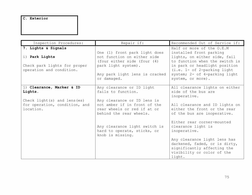
75
Inspection Procedures: Repair if: Recommended Out of Service if:
7. Lights & Signals
i) Park Lights
Check park lights for proper
operation and condition.
One (1) front park light does
not function on either side
(four either side (four (4)
park light system).
Any park light lens is cracked
or damaged.
Half or more of the O.E.M
installed front parking
lights, on either side, fail
to function when the switch is
in park or headlight position
(i.e. 1- of 2-parking light
system; 2- of 4-parking light
system, or more).
j) Clearance, Marker & ID
Lights.
Check light(s) and lens(es)
for operation, condition, and
location.
Any clearance or ID light
fails to function.
Any clearance or ID lens is
not amber if in front of the
rear wheels or red if at or
behind the rear wheels.
Any clearance light switch is
hard to operate, sticks, or
knob is missing.
All clearance lights on either
side of the bus are
inoperative.
All clearance and ID lights on
either the front or the rear
of the bus are inoperative.
Either rear corner-mounted
clearance light is
inoperative.
Any clearance light lens has
darkened, faded, or is dirty,
significantly affecting the
visibility or color of the
light.
C. Exterior

76
Inspection Procedures: Repair if: Recommended Out of Service if:
7. Lights & Signals
Any clearance or ID light lens
is damaged and no white light
is visible.
Any clearance or ID light lens
is damaged and white light is
visible.
k) License plate/light(s):
Check license plate lights(s)
and lens(es) for condition and
operation.
l) Strobe light:
Check roof mounted white
flashing strobe light for
operation, location, and
condition.
License plate light(s) is
inoperative.
Strobe light fails to
function. Switch is hard to
operate or sticks. Strobe
light lens is cracked or
damaged.
Strobe light is missing or
does not function.
8. Reflectors:
Check reflectors for condition
and location.
Any reflector is damaged,
cracked or faded.
Any required reflectors are
missing. Any pieces from crack
missing.
C. Exterior
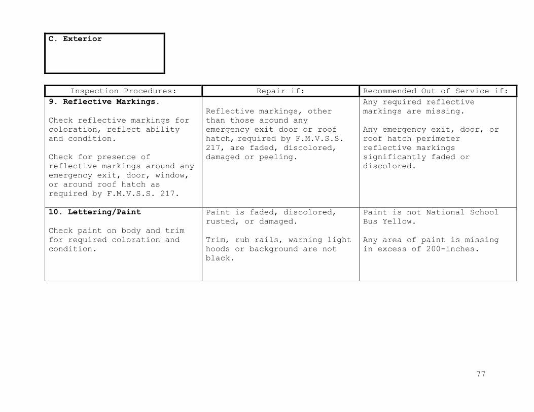
77
Inspection Procedures: Repair if: Recommended Out of Service if:
9. Reflective Markings.
Check reflective markings for
coloration, reflect ability
and condition.
Check for presence of
reflective markings around any
emergency exit, door, window,
or around roof hatch as
required by F.M.V.S.S. 217.
Reflective markings, other
than those around any
emergency exit door or roof
hatch, required by F.M.V.S.S. 217, are faded, discolored,
damaged or peeling.
Any required reflective
markings are missing.
Any emergency exit, door, or
roof hatch perimeter
reflective markings
significantly faded or
discolored.
10. Lettering/Paint
Check paint on body and trim
for required coloration and
condition.
Paint is faded, discolored,
rusted, or damaged.
Trim, rub rails, warning light
hoods or background are not
black.
Paint is not National School
Bus Yellow.
Any area of paint is missing
in excess of 200-inches.
C. Exterior

78
Inspection Procedures: Repair if: Recommended Out of Service if:
10. Lettering/Paint
Check all lettering for
required type, size, location,
and color.
Fuel type lettering is not
present.
Four inch (4”) high bus number
missing from sides or back of
the bus or missing from front
bumper.
Any required lettering is not
readable.
Bus is not equipped with the
following lettering:
1) Eight inch (8”) front and rear.
2) Four inch (4”)“Name of” county or city public
schools on the left and
right sides of the body.
3) Handicap symbol for wheelchair equipped buses
starting 1992.
4) Minimum two inch (2”) lettering “Emergency Door”
at top or above the door.
5) Emergency door(s) (all years) and window(s) or
hatch(es) (1990 and later)
not labeled “Emergency Exit”
or “Emergency Door” on
inside or outside.
Any bus with wheel chair lift
and handicap symbol is not
reflective white on blue
background, maximum of 12
square inches.
C. Exterior

79
Inspection Procedures: Repair if: Recommended Out of Service if:
11. Mirrors
Mirror brackets are bent or
broken, or mounting is
insecure and mirror will
remain properly adjusted.
Mirror brackets are bent or
broken, or mounting is
insecure and mirror will not
stay in the adjusted position
or cannot be adjusted.
Cross view mirrors will not
stay beyond the leading edge
of the vehicle.
Any mirror reflective surface
deteriorated.
Reflecting surface of the
mirror is cracked, broken,
peeled, pitted, clouded,
tarnished, has sharp edges,
reflects more than one image,
or is not mounted securely.
12. Storage & Chain Boxes.
Check latches, hinges, and
seals.
Latches or hinges broken.
Seals deteriorated.
Unwanted or unauthorized
items.
C. Exterior

80
Inspection Procedures: Repair if: Recommended Out of Service if:
1. All Belts
A) Tension
Visually and physically check
all drive belts for proper
tension. (fig 1, pg 133)
Note: If available, use a
tension gauge. If a gauge is
not available, use a ruler to
measure the deflection of the
belt(s) up and down at the
widest point between the drive
and driven pulley(s).
Any belt exceeds tension
reading recommended by
manufacturer, if a tension gauge is used.
(fig 1, page 133)
Using ruler method, any belt
is less than ½-inch deflection
(too tight) when firm pressure
is applied. (fig 2, page 133)
Any belt tensioner does not
pivot or move and apply spring
pressure on belt.
Tension on any belt is too
loose (based on specifications
of type tension gauge used).
Tension of any belt (using
ruler method) is too loose
when firm pressure is applied.
B) Belt Alignment
Visually inspect belts for
proper alignment.
Any belt not inline (less than
1/16 inch per foot).
Belt misalignment is excessive
and could result in failure
(More than 1/16 inch per
foot).
D. Engine Compartment

81
Inspection Procedures: Repair if: Recommended Out of Service if:
1. All Belts
C) Condition
Visually inspect belt(s) for
glazing, oil contamination,
dry rotting, cuts, and
separation of plies. Check
belts for twisting or
distortion.
Any belts are glazed.
Any belt is oil saturated,
dry-rotted, or cut or plies of
belt(s) are separated.
D) Routing
Visually inspect belt(s) for
rubbing or contact with
objects other than pulleys and
for routing around correct
pulleys.
Any belt is making contact
with objects other than
pulley(s).
Any belt is routed around
incorrect pulley(s).
2. Leaks
A) Fuel Tank
Inspect fuel tank assembly for
leaks.
There is any fuel leakage from
the tank, connections, or cap,
or cap is missing. The fuel
tank has any cracks. Any
connection(s) are loose at the
tank.
D. Engine Compartment

82
Inspection Procedures: Repair if: Recommended Out of Service if:
2. Leaks
B) Coolant
Inspect all potential
locations for coolant leaks.
There is coolant seepage at
radiator, hoses, heater core,
engine oil cooler, thermostat
housing, head gaskets, freeze
plugs, reservoir, water pump,
or other potential locations.
Leakage is excessive and could
result in imminent engine
failure.
C) Oil
Inspect for engine oil leaks
at all potential locations and
determine severity.
Engine oil leakage is causing
deterioration of any rubber
parts, such as steering
linkage boots, hoses, etc.
Engine oil is dripping at any
location except on exhaust
system.
Leakage is excessive and could
result in imminent engine
failure.
Engine oil is dripping on any
portion of the exhaust system.
There is a drip shield
installed to divert oil from
the exhaust system.
D. Engine Compartment

83
Inspection Procedures: Repair if: Recommended Out of Service
if:
2. Leaks
D) Power Steering
Inspect for power steering
fluid leak at all potential
locations and determine
severity.
Power steering fluid is
causing deterioration of any
rubber parts, such as
steering linkage boots,
hoses, etc.
Power steering fluid is
seeping.
Power steering fluid is
dripping.
Power steering reservoir cap
or dipstick is missing.
E) Exhaust System
With engine running and at
operating temperature,
inspect exhaust system for
leaks, condition, and
securement.
There is any physical damage
to exhaust system.
Any exhaust junction gasket
or hardware is broken or missing.
There is any leakage, which
is audible or can be felt
around any portion of the
exhaust system including
manifold(s), pipe sections,
or any junction.
Tail pipe opening smashed or
pinched.
Exhaust does not discharge at
or within 15-inches forward
of the rearmost part of the
vehicle for diesel and 6-
inches forward of the
rearmost part of the vehicle
for gasoline vehicles.
D. Engine Compartment

84
Inspection Procedures: Repair if: Recommended Out of Service if:
2. Leaks
Exception: Type A buses may
discharge behind the rear
wheel.
3. Road Speed Governor(If
Equipped).
Check for proper connections.
Check governor performance and
shutdown of engine.
Engine will not shutdown.
Governor does not limit engine
RPM
4. Fan Assembly.
Check fan blade and fan clutch
assembly for securement and
condition.
Fan has any cracked, bent, or
broken blades.
Any portion of fan mounting is
loose. Fan clutch is seized or
loose.
Any leak, mounting, rotation
or function problem with
hydraulic motor. Electric fan
does not operate.
Hydraulic solenoid valve
inoperative.
Wiring for fan (electric) or
solenoid (hydraulic) is not
secured, loose, damaged, or
missing.
D. Engine Compartment

85
Inspection Procedures: Repair if: Recommended Out of Service if:
5. Water Pump.
Check condition of water pump
and pulley.
There is evidence of coolant
seepage from water pump, seal,
gasket surface, or weep hole.
Water pump fasteners are
loose, damaged, or missing.
Water pump is noisy, bearing
is damaged, or coolant is
dripping out.
6. Air Compressor.
Check securement and condition
of the air compressor, and
filter assembly.
Air compressor air filter (if
equipped) is dirty.
Any loose, leaking or damaged
hose or plumbing between
engine air filtration system
and compressor (on vehicle
that share filter).
Any portion of the air
compressor, compressor sir
filter (if equipped), filter
cover or fastener is cracked,
loose or missing.
D. Engine Compartment

86
Inspection Procedures: Repair if: Recommended Out of Service if:
6. Air Compressor
Compressor drive belts in
condition of impending or
probable failure.
Any problem with piggy- backed
power steering pumps either
mounting or leaks.
7. All Piping and Hoses.
Check for proper routing and
securement.
Check for securement.
Routing securement in
condition of impending or
probable system failure.
8. All Wiring.
Check routing, securement, and
condition of all wiring and
any electrical cable in the
engine compartment.
There is any loose, damaged,
or corroded wiring connector
or terminal end.
There is any unsecured or
poorly routed wiring that
could cause potential short or
fire due to abrasion or heat
damage.
There is any burnt wiring or
wiring (other than ground
wires) missing insulation.
D. Engine Compartment

87
Inspection Procedures: Repair if: Recommended Out of Service if:
9. Steering Gear and Hydraulic
Pump.
Check fluid level.
Check mounting bolts.
Fluids below operating level.
Any mounting bolts loose or
missing.
Frame, frame associated rivets
or fasteners are loose,
damaged or missing.
There is any binding in gear
box.
Any cracks in gear box or
mounting brackets.
10. Master Cylinder.
Check fluid level.
Level of brake fluid in either
side of master cylinder
reservoir is lower than ¼-inch
from top or below “Add” mark.
D. Engine Compartment

88
Inspection Procedures: Repair if: Recommended Out of Service if:
10. Master Cylinder
Check mounting bolts.
Brake fluid or power-assist
fluid shows evidence of
excessive water, oil, or dirt
contamination. Brake power-
assist hydraulic fluid is
below cold “Add” mark.
Any mounting bolts loose or
missing.
11. Vacuum, Electric, and
Hydraulic Brake Boosters.
Check all connections and
mounting.
Lines and hoses are leaking.
The system leaks. Lines and
hoses are collapsed, broken,
chafed, insecurely mounted,
less than 1 ½-inch from any
part of the exhaust system.
Clamps are loose or broken.
Any tank is missing, loose,
damaged or leaking.
The vacuum booster is loose,
damaged or mounting is
cracked.
D. Engine Compartment

89
Inspection Procedures: Repair if: Recommended Out of Service if:
12. Radiator Mounting
Check radiator assembly and
mounting for securement and
condition.
Any portion of radiator or
mounting system is cracked, damaged, or has loose or
missing fasteners.
Any portion of the radiator is
cracked and leaking.
13. Fuel System, Fuel Lines &
Carburetor (if equipped)
Visually check the condition,
operation, and securement of
all fuel system
components,
including, pumps, fuel lines
and routing in the engine
compartment.
There is evidence of
contamination in the water
separator (if equipped).
There is any unsecured, or
poorly routed or loose fuel
line or hose that could cause
potential fire due to abrasion
or heat damage.
D. Engine Compartment

90
Inspection Procedures: Repair if: Recommended Out of Service if:
14. Fuel System, Fuel Lines &
Carburetor (if equipped).
Any fuel system connection or
component that is stripped,
loose, cracked, or leaking.
Any fuel system component is
damaged or not mounted
securely.
Any evidence of fuel leaking
internally and contaminating
oil or coolant (pump, tubes,
etc).
Any electric or mechanical
shutdown that does not operate
properly.
Any accelerator return spring
weak, broken, or missing.
15. Batteries
a. Batteries:
1) Check for condition and
type.
Batteries are the wrong type
for vehicle, or in multi
battery sets are not matched.
Batteries top or sides are
corroded, greasy, dirty, wet
with electrolyte.
Battery is cracked or damaged.
Battery will not start
vehicle.
D. Engine Compartment

91
Inspection Procedures: Repair if: Recommended Out of Service if:
15. Batteries
b. Hold-down
1) Check for tightness,
condition, and type of battery
hold-down.
c. Battery Terminals.
1) Check terminals for type,
clean-liness, tightness, and
condition.
d. Battery Cables
1) Check cable assemblies for
routing, securement,
condition, and size.
Electrolyte is low. (if
applicable).
Hold–down assembly tray is
corroded or damaged but
battery is secure.
Terminals are dirty, corroded
or loose and/or missing.
Cable corroded.
Negative cable or insulation
is cracked or damaged.
Hold-down assembly or tray is
loose, corroded, or damaged
causing insecure mounting of
battery.
Hold down is flexible strap or
other non-rigid design.
Hold-down /batteries are
mounted in such a way that
they could short out against
the hold-down and /or any body
or chassis component.
Batteries have the wrong style
terminals for vehicle, or are
installed with adapters.
Positive cable is cracked or
damaged.
D. Engine Compartment
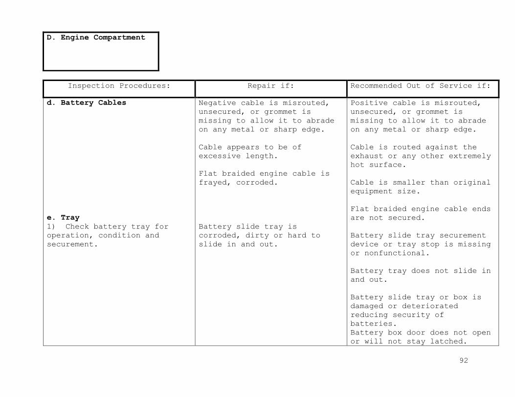
92
Inspection Procedures: Repair if: Recommended Out of Service if:
d. Battery Cables
e. Tray
1) Check battery tray for
operation, condition and
securement.
Negative cable is misrouted,
unsecured, or grommet is
missing to allow it to abrade
on any metal or sharp edge.
Cable appears to be of
excessive length.
Flat braided engine cable is
frayed, corroded.
Battery slide tray is
corroded, dirty or hard to
slide in and out.
Positive cable is misrouted,
unsecured, or grommet is
missing to allow it to abrade
on any metal or sharp edge.
Cable is routed against the
exhaust or any other extremely
hot surface.
Cable is smaller than original
equipment size.
Flat braided engine cable ends
are not secured.
Battery slide tray securement
device or tray stop is missing
or nonfunctional.
Battery tray does not slide in
and out.
Battery slide tray or box is
damaged or deteriorated
reducing security of
batteries.
Battery box door does not open
or will not stay latched.
D. Engine Compartment
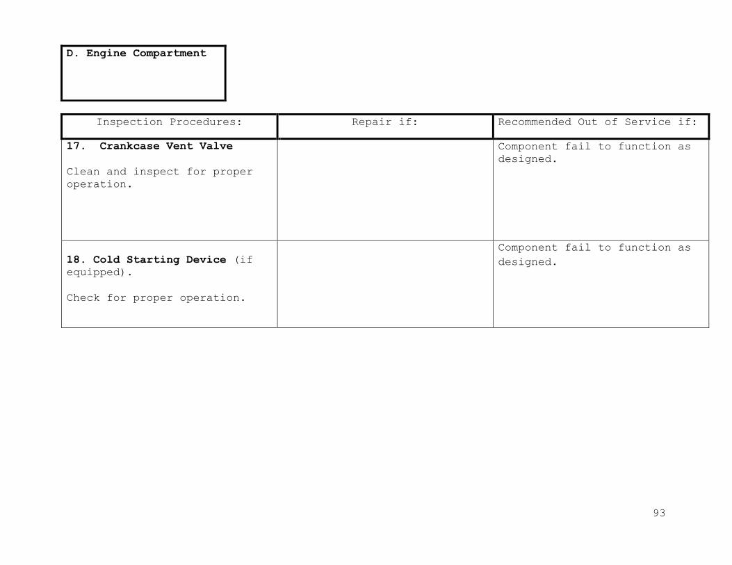
93
Inspection Procedures: Repair if: Recommended Out of Service if:
17. Crankcase Vent Valve
Clean and inspect for proper
operation.
Component fail to function as
designed.
18. Cold Starting Device (if
equipped).
Check for proper operation.
Component fail to function as
designed.
D. Engine Compartment

94
Inspection Procedures: Repair if: Recommended Out of Service if:
19. Turbocharger
1) Check mounting bolts.
2) Check air intake and
exhaust hoses and piping for
tightness.
Mounting bolts loose.
Hoses and piping loose.
20. Vibration Damper.
Check for play or looseness.
Out of manufacturer’s
specification.
21. Engine Mounts.
Inspect front and rear
insulators for deterioration
and looseness.
Mounting bolts not tightened
to factory specification.
Insulators deteriorated.
Engine mounts broken or
missing.
D. Engine Compartment

95
Inspection Procedures: Repair if: Recommended Out of Service if:
22. Cooling System.
Check coolant level
(antifreeze) level and
condition.
Coolant level in radiator or
reservoir is low but still
visible in the tank.
Coolant shows evidence of rust
and corrosion contamination.
Coolant level in radiator or
reservoir is low and not
visible in tank.
Coolant shows evidence of
excessive oil or fuel
contamination.
D. Engine Compartment

96
Inspection Procedures: Repair if: Recommended Out of Service if:
1. Fluid Leaks.
Check for fluid leaks at wheel
seals, backing plates and
underside of engine.
Ether front wheel seal is
damaged or leaking
2. Steering Linkage.
A. Drag link (if equipped)
Check the drag link ends,
shaft and fasteners for
looseness and condition.
Drag link has more than 1/16-
inch and less than 1/8-inch
axial play.
Any drag link end fitting (as
equipped) is loose, or
missing, or will not take
grease.
Drag link end boot is damaged
or missing.
Drag needs lubrication.
Any motion, other than
rotational, between any
linkage member and its
attachment point of more than
1/8-inch measured with hand
pressure only.
Loose clamps, clamp bolts on
tie rod ends or drag links.
E. Front Axle

97
Inspection Procedures: Repair if: Recommended Out of Service if:
2. Steering Linkage.
B. Pitman Arm
Check the pitman arm for
looseness or misalignment at
sector shaft splines &
looseness at all joints. Check
loose-ness of pinch bolt &
fasteners & condition of
pitman arm.
Pitman arm grease fitting (if
originally equipped) is loose
or missing.
Any looseness of the pitman
arm on the steering gear box,
output shaft or gear box.
Pinch bolt at sector shaft is
loose or missing.
C. Steering Arm
1) Check upper steer-ing arm
(Acker-man Arm) & left & right
side lower steering arms for
securement & condition.
2) Check condition &
securement of steering stops &
lock nuts.
Any steering arm has bent, is
cracked, or is damaged.
Any steering arm attachment
point is loose, or any
fasteners or cotter pin is
missing.
Either steering stop or lock
is loose, damaged, or missing.
D. Tie Rod and Ends
1) Check Tie rod ends, tie
rod, dust boots, & clamps or
fasteners (as equip-ped) for
looseness,
damage, & condition.
Tie rod end needs lubrication.
Tie rod end clamps, fasteners,
or cotter pin is stripped,
missing or loose.
E. Front Axle

98
Inspection Procedures: Repair if: Recommended Out of Service if:
2. Steering Linkage.
Any tie rod end grease fitting
is loose, or missing, or will
not take grease.
Any tie rod end has more than
1/16-inch and less than 1/8-
inch play. (see fig 4, page
134)
Any clamp (as equipped) not
positioned.
Any tie rod end is cracked or
damaged.
Any tie rod or end bent,
cracked, broken, or threads
are damaged in any way.
Any tie rod end has more than
1/8 inch axial play. (see fig
4, page 134).
Tie rod end has more than end
ball stud is loose in steering
arm or idler arm. (fig 5, page
135).
3. Shock Absorbers.
Inspect shocks for condition
and securement
There is wetness around shock
body due to leaking shock
fluid.
Any shock mounting or fastener
is loose, missing, cracked, or
broken.
Any shock is broken.
Any shock fails to function.
E. Front Axle

99
Inspection Procedures: Repair if: Recommended Out of Service if:
4. Brake Lining.
Inspect linings and foundation
brake hardware for
contamination, wear, damage, and securement.
Lining wear is extremely
uneven left and right.
Brake lining is worn to or
beyond allowable limits.
Lining is broken, cracked, or
loose on shoe.
Friction surface is
contaminated with oil, grease,
or brake fluid.
Lining is not the proper size.
Shoe platform or web is
cracked or damaged.
There is any loose, damaged,
or missing foundation brake
hardware within the drum.
5. Slack Adjusters.
A. Inspect slack adjusters and
S-cam assemblies for wear,
condition, operation and
securement.
Any portion of slack adjuster
or S-cam is missing, broken,
cracked, or badly worn.
Slack adjuster is not mounted
properly or anchor bracket is
loose or damaged.
E. Front Axle
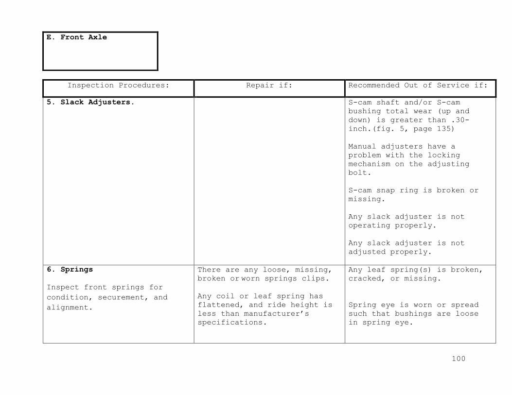
100
Inspection Procedures: Repair if: Recommended Out of Service if:
5. Slack Adjusters.
S-cam shaft and/or S-cam
bushing total wear (up and
down) is greater than .30-
inch.(fig. 5, page 135)
Manual adjusters have a
problem with the locking
mechanism on the adjusting
bolt.
S-cam snap ring is broken or
missing.
Any slack adjuster is not
operating properly.
Any slack adjuster is not
adjusted properly.
6. Springs
Inspect front springs for
condition, securement, and
alignment.
There are any loose, missing,
broken or worn springs clips.
Any coil or leaf spring has
flattened, and ride height is
less than manufacturer’s
specifications.
Any leaf spring(s) is broken,
cracked, or missing.
Spring eye is worn or spread
such that bushings are loose
in spring eye.
E. Front Axle

101
Inspection Procedures: Repair if: Recommended Out of Service if:
6. Springs
Either front spring saddle (if
equipped) is worn out or
missing.
Rubber frame bumper is missing.
Ride height not adjusted
properly (air suspension).
Any coil spring(s) is broken,
insecurely mounted, non-O.E.M.
or non-O.E.M. blocks or spacers
are installed.
There is any misalignment of
spring leaves or other evidence
that center pin is loose or
broken.
Either front coil or leaf
spring is worn so that rubber
frame bumper is damaged or worn
due to frequent bottoming of
front suspension.
Any alignment wedge is loose or
damaged.
On any air bag type spring
assembly, air bag is damaged or
leaking or airlines and valves
are damaged or leaking.
a. U-Bolts
Inspect spring U-bolts for
condition and securement.
Any U-bolt is misaligned.
There is rust underneath U-bolt
nuts indicating possibility of
looseness.
E. Front Axle
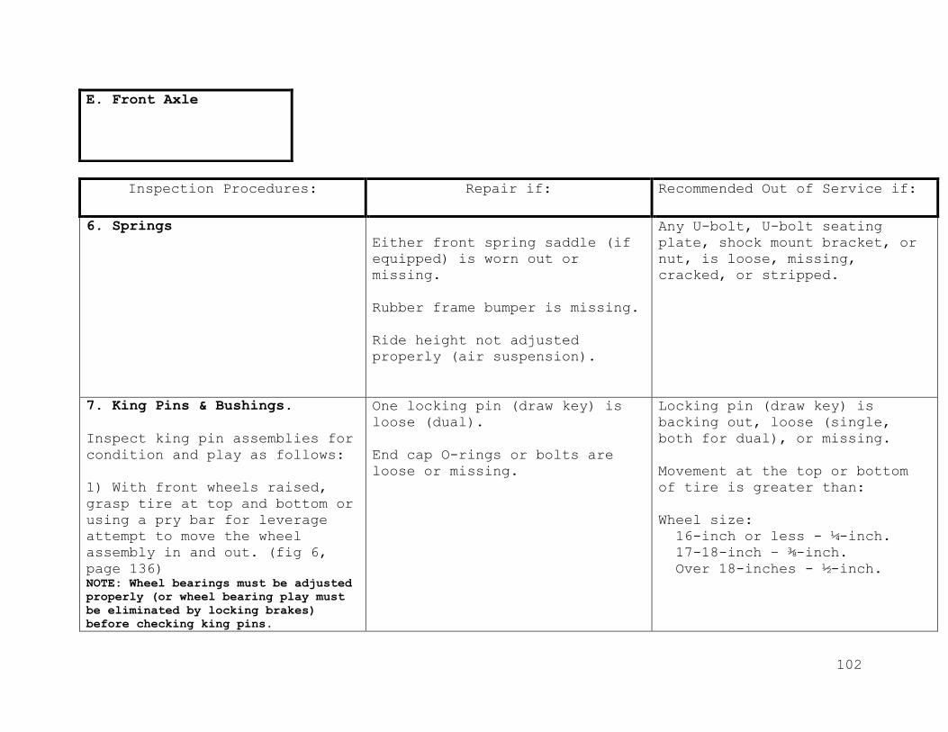
102
Inspection Procedures: Repair if: Recommended Out of Service if:
6. Springs
Either front spring saddle (if
equipped) is worn out or
missing.
Rubber frame bumper is missing.
Ride height not adjusted
properly (air suspension).
Any U-bolt, U-bolt seating
plate, shock mount bracket, or
nut, is loose, missing,
cracked, or stripped.
7. King Pins & Bushings.
Inspect king pin assemblies for
condition and play as follows:
1) With front wheels raised,
grasp tire at top and bottom or
using a pry bar for leverage
attempt to move the wheel
assembly in and out. (fig 6,
page 136) NOTE: Wheel bearings must be adjusted
properly (or wheel bearing play must
be eliminated by locking brakes)
before checking king pins.
One locking pin (draw key) is
loose (dual).
End cap O-rings or bolts are
loose or missing.
Locking pin (draw key) is
backing out, loose (single,
both for dual), or missing.
Movement at the top or bottom
of tire is greater than:
Wheel size:
16-inch or less - ¼-inch.
17-18-inch – ⅜-inch.
Over 18-inches - ½-inch.
E. Front Axle
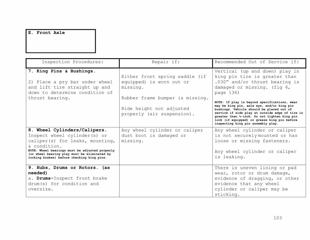
103
Inspection Procedures: Repair if: Recommended Out of Service if:
7. King Pins & Bushings.
2) Place a pry bar under wheel
and lift tire straight up and
down to determine condition of
thrust bearing.
Either front spring saddle (if
equipped) is worn out or
missing.
Rubber frame bumper is missing.
Ride height not adjusted
properly (air suspension).
Vertical (up and down) play in
king pin tire is greater than
.030” and/or thrust bearing is
damaged or missing. (fig 6,
page 136)
NOTE: If play is beyond specifications, wear
may be king pin, axle eye, and/or king pin
bushings. Vehicle should be placed out of
service if side play at outside edge of tire is
greater than ¼-inch. Do not tighten king pin
lock (if equipped) or grease king pin before
inspecting king pin assembly play.
8. Wheel Cylinders/Calipers.
Inspect wheel cylinder(s) or
caliper(s) for leaks, mounting,
& condition. NOTE: Wheel bearings must be adjusted properly
(or wheel bearing play must be eliminated by
locking brakes) before checking king pins.
Any wheel cylinder or caliper
dust boot is damaged or
missing.
Any wheel cylinder or caliper
is not securely mounted or has loose or missing fasteners.
Any wheel cylinder or caliper
is leaking.
9. Hubs, Drums or Rotors. (as
needed)
a. Drums-Inspect front brake
drum(s) for condition and
oversize.
There is uneven lining or pad
wear, rotor or drum damage,
evidence of dragging, or other
evidence that any wheel
cylinder or caliper may be
sticking.
E. Front Axle
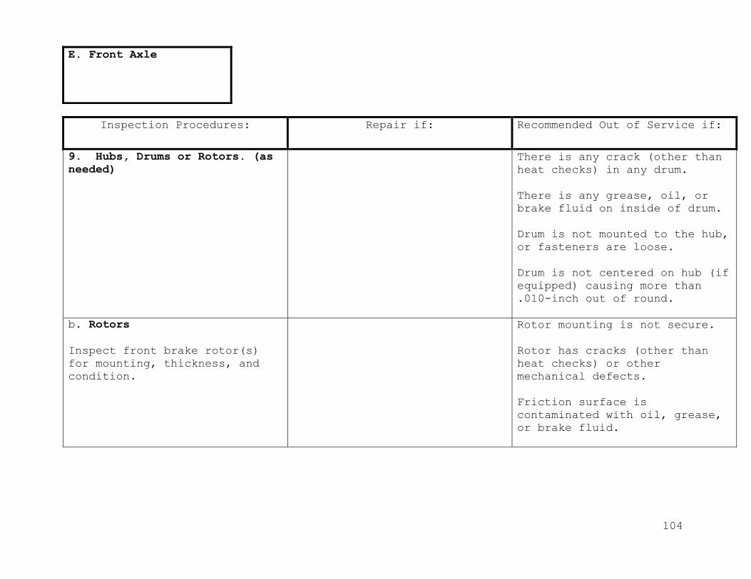
104
Inspection Procedures: Repair if: Recommended Out of Service if:
9. Hubs, Drums or Rotors. (as
needed)
There is any crack (other than
heat checks) in any drum.
There is any grease, oil, or
brake fluid on inside of drum.
Drum is not mounted to the hub,
or fasteners are loose.
Drum is not centered on hub (if
equipped) causing more than
.010-inch out of round.
b. Rotors
Inspect front brake rotor(s)
for mounting, thickness, and
condition.
Rotor mounting is not secure.
Rotor has cracks (other than
heat checks) or other
mechanical defects.
Friction surface is
contaminated with oil, grease,
or brake fluid.
E. Front Axle
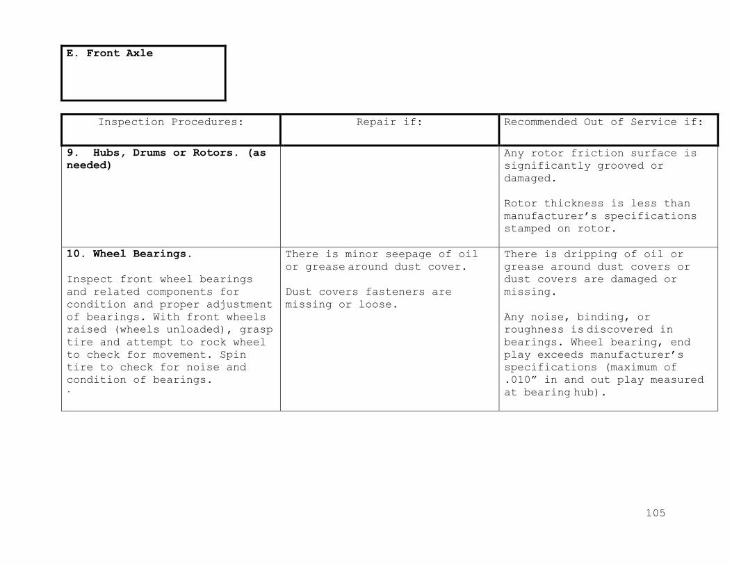
105
Inspection Procedures: Repair if: Recommended Out of Service if:
9. Hubs, Drums or Rotors. (as
needed)
Any rotor friction surface is
significantly grooved or
damaged.
Rotor thickness is less than
manufacturer’s specifications
stamped on rotor.
10. Wheel Bearings.
Inspect front wheel bearings
and related components for
condition and proper adjustment
of bearings. With front wheels
raised (wheels unloaded), grasp
tire and attempt to rock wheel
to check for movement. Spin
tire to check for noise and condition of bearings. .
There is minor seepage of oil
or grease around dust cover.
Dust covers fasteners are
missing or loose.
There is dripping of oil or
grease around dust covers or
dust covers are damaged or
missing.
Any noise, binding, or
roughness is discovered in bearings. Wheel bearing, end
play exceeds manufacturer’s
specifications (maximum of
.010” in and out play measured
at bearing hub).
E. Front Axle

106
Inspection Procedures: Repair if: Recommended Out of Service if:
10. Wheel Bearings.
NOTE: It is important to
correctly identify the source
of any play. To determine if
the play is in wheel bearings,
have an assistant fully apply
brakes while rechecking play.
If movement disappears with
brakes applied, then play was
in wheel bearings.
11. Wheel Balance.
As necessary.
12. Alignment
Inspect tires for evidence of
proper alignment.
Any tire is feather-edged,
cupped, or has uneven tread wear.
Lateral run out of any tire/rim
assembly exceeds ¼-inch.
Tires/wheels are grossly
misaligned, affecting steering
control.
E. Front Axle

107
Inspection Procedures: Repair if: Recommended Out of Service if:
1. Fluid leaks.
Check for leaks at wheel seals,
backing plates, pinion seal,
differential and cover
Differential gasket or pinion
seal is seeping.
Differential gaskets or pinion
seals are leaking.
2. Vent
Inspect condition of axle
housing vent.
Vent cap is clogged.
Vent hose (if originally
equipped) is cracked, clogged,
or missing.
Axle vent is not functional or
is missing.
3. Shock Absorbers.
Inspect rear shocks for
condition and securement.
There is any wetness around
shock body due to leaking shock
fluid.
Any shock is broken.
Any shock fails to function.
Any shock mounting or fastener
is loose, missing, cracked, or
broken.
F. Rear Axle
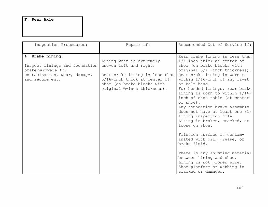
108
Inspection Procedures: Repair if: Recommended Out of Service if:
4. Brake Lining.
Inspect linings and foundation
brake hardware for contamination, wear, damage,
and securement.
Lining wear is extremely
uneven left and right.
Rear brake lining is less than
5/16-inch thick at center of
shoe (on brake blocks with original ¾-inch thickness).
Rear brake lining is less than
1/4-inch thick at center of
shoe (on brake blocks with
original 3/4 -inch thickness).
Rear brake lining is worn to
within 1/16-inch of any rivet
or bolt head.
For bonded linings, rear brake
lining is worn to within 1/16-
inch of shoe table (at center
of shoe).
Any foundation brake assembly
does not have at least one (1)
lining inspection hole.
Lining is broken, cracked, or
loose on shoe.
Friction surface is contam-
inated with oil, grease, or
brake fluid.
There is any shimming material
between lining and shoe.
Lining is not proper size.
Shoe platform or webbing is
cracked or damaged.
F. Rear Axle

109
Inspection Procedures: Repair if: Recommended Out of Service if:
4. Braking Lining.
There is any loose, damaged,
or missing foundation brake
hardware within the drum.
5. Slack Adjusters.
Inspect slack adjusters and S-
cam assemblies for wear,
condition, operation, and
securement.
Slack adjuster is mounted so
that adjuster bolt is facing chamber.
Any portion of slack adjuster
or S-cam is missing, broken,
cracked, or badly worn.
S-cam shaft and/or S-cam
bushing total wear (up and
down) is greater than
.030"(fig 5, page 135)
S-cam in and out end play is
more than .060 inch (fig 5,
page 135). S-cam snap ring is
missing.
Slack adjuster has frozen or
stripped worm gear or ratchet
assembly.
6. Springs
Inspect rear springs for
condition, securement, and
alignment.
There are any loose, missing,
broken, or worn spring clips
(note).
Any leaf spring or air
suspension ride height is less
than manufacturer’s
specifications.
Any leaf spring is broken,
cracked or missing.
F. Rear Axle

110
Inspection Procedures: Repair if: Recommended Out of Service if:
6. Springs
Missing insulators between
leafs.
Either rear spring saddle (if
equipped) is worn out or
missing.
Rubber frame bumper is
missing.
Any coil or leaf spring has
weakened, and vehicle is
leaning excessively.
Ride height not adjusted
properly (air suspension).
On any air bag type spring
assembly, air bag is damaged
or leaking, or air lines and
valves are damaged or leaking.
Air ride pivot pins and
bushings are loose.
There is any misalignment of
spring leaves or other
evidence that centering pin is
loose or broken.
Either rear leaf spring is
worn to the point that
suspension bottoming has
damaged rubber frame bumper.
a. U-Bolts
Inspect spring U-bolts for
condition and securement.
Any U-bolt is misaligned.
There is rust underneath U-
bolt nuts indicating
possibility of looseness.
Any U-bolt, U-bolt seating
plate, shock mount bracket, or
nut, is loose, missing,
cracked, or stripped.
F. Rear Axle

111
Inspection Procedures: Repair if: Recommended Out of Service if:
7. Wheel
Cylinders/Calipers.
Inspect wheel cylinder(s) or
caliper(s) for leaks, mounting,
and condition.
Any wheel cylinder or caliper
dust boot is damaged or
missing.
Any wheel cylinder or caliper
is not securely mounted or has loose or missing fasteners.
Any wheel cylinder or caliper
is leaking.
8. Hubs, Drums or Rotors
(as needed)
a. Drums
Inspect front brake drum(s) for
condition and oversize.
There is uneven lining or pad
wear, rotor or drum damage,
evidence of dragging, or other
evidence that any wheel
cylinder or caliper may be
sticking.
F. Rear Axle

112
Inspection Procedures: Repair if: Recommended Out of Service if:
8. Hubs, Drums or Rotors (as
needed)
There is any grease, oil, or
brake fluid on inside of drum.
Drum is not mounted to the hub,
or fasteners are loose.
Drum is not centered on hub (if
equipped) causing more than
.010-inch out of round.
b. Rotors
Inspect front brake rotor(s)
for mounting, thickness, and
condition.
Rotor mounting is not secure.
Rotor has cracks (other than
heat checks) or other
mechanical defects.
Friction surface is
contaminated with oil, grease,
or brake fluid.
Any rotor friction surface is
significantly grooved or
damaged.
F. Rear Axle

113
Inspection Procedures: Repair if: Recommended Out of Service if:
8. Hubs, Drums or Rotors (as
needed)
Rotor thickness is less than
manufacturer’s specifications
stamped on rotor.
9. Wheel Bearings
Inspect rear wheel bearings for
condition and proper adjustment
of bearings.
a) Raised rear wheels (wheels
unloaded), and release park
brake.
b) Grasp tire and attempt to
rock wheel to check for
movement.
There is any detectable
looseness or roughness in rear
wheel bearings.
10. Wheel Seals
Inspect rear wheel seals for
condition and leakage.
There is wetness or dripping of
oil or grease around axle
flange
Either rear wheel seal is
damaged or leaking
excessively.
Any axle flange stud or nut is
loose or missing.
F. Rear Axle

114
Inspection Procedures: Repair if: Recommended Out of Service if:
1. Exhaust Systems.
a. Exhaust Leaks
With engine running and at
operating temperature, inspect
exhaust system for
leaks, condition, and
securement.
Any exhaust junction gasket or
hardware is broken or missing.
There is any physical damage to
exhaust system (note).
b. Mounting
Inspect mounting of the exhaust
system.
There is any exhaust system
hanger, which is not securely
mounted.
Any exhaust pipe or clamp is
loose.
There is any originally
installed exhaust hanger, which
is missing, broken, or detached
from exhaust system or frame
mounting point.
Clamp is missing.
G. Under Bus
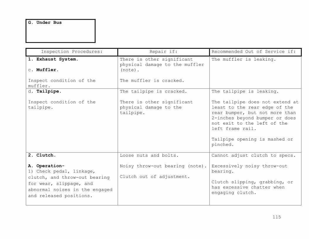
115
Inspection Procedures: Repair if: Recommended Out of Service if:
1. Exhaust System.
c. Muffler.
Inspect condition of the
muffler.
There is other significant
physical damage to the muffler
(note).
The muffler is cracked.
The muffler is leaking.
d. Tailpipe.
Inspect condition of the
tailpipe.
The tailpipe is cracked.
There is other significant
physical damage to the
tailpipe.
The tailpipe is leaking.
The tailpipe does not extend at
least to the rear edge of the
rear bumper, but not more than
2-inches beyond bumper or does
not exit to the left of the
left frame rail.
Tailpipe opening is mashed or
pinched.
2. Clutch.
A. Operation-
1) Check pedal, linkage,
clutch, and throw-out bearing
for wear, slippage, and
abnormal noises in the engaged
and released positions.
Loose nuts and bolts.
Noisy throw-out bearing (note).
Clutch out of adjustment.
Cannot adjust clutch to specs.
Excessively noisy throw-out
bearing.
Clutch slipping, grabbing, or
has excessive chatter when
engaging clutch.
G. Under Bus

116
Inspection Procedures: Repair if: Recommended Out of Service
if:
2. Clutch.
2) Visually check clutch
pedal pad for wear.
3) Check clutch master and
slave cylinders for hydraulic
leaks and operation (if
equipped).
Worn pedal cover pad
Binding or sticking clutch
linkage or return spring.
Hard to shift transmission.
Metal pedal cover pad is
missing.
Leaking master or slave
cylinder or inoperable.
B. Adjustment
1) Check “free play” travel
of the clutch pedal. This is
the first easy movement of
the clutch pedal and should
be no more than 1-1/2-inch
and no less than 3/4- inch of
travel.
“Free play” is out of
adjustment.
Clutch slips, grabs, or
chatters after adjusting
“free play” travel.
No adjustments can be made.
G. Under Bus

117
Inspection Procedures: Repair if: Recommended Out of Service
if:
3. Air Tanks.
a. Reservoir Mounting.
Inspect reservoirs (air
vacuum tanks) for securement
and condition.
Any reservoir mounting strap
or fastener is cracked,
loose, or missing.
b. Bleed Air Reservoir.
1) With air system fully
charged, check manual operation of safety relief valve.
2) Partially open manual
petcock valve on the first
(wet) tank.
3) Allow draining until any
moisture (water) or
contamination is drained.
There is moisture in
reservoir (desiccant type air dryer equipped vehicles
only).
Safety relief valve leaks or
does not release pressure.
There is excessive sludge or
oil contamination in the reservoir (more than 8-fluid
ounces).
Reservoir leaks due to
corrosion or is cracked.
Release valve does not close.
G. Under Bus

118
Inspection Procedures: Repair if: Recommended Out of Service if:
4. Transmission
a. Transmission Bolts.
1) Inspect transmission
assembly and mounting
fasteners for condition and
securement.
Any transmission assembly
fastener loose, missing or damaged.
Transmission is not mounted
securely to flywheel housing.
There is any external
indication that any torque
converter bolt(s) is loose or
missing.
b. Linkage
1) Inspect transmission
linkage for routing, condition, and securement.
Note: Mechanical modulator
cable should have 1/16- to
1/8-inch clearance at full
throttle.
Modulator cable or vacuum hose
is routed where it is subject
to excessive heat or abrasion.
Any linkage hardware or
fasteners are loose.
Modulator cable is exposed or
casing is damaged.
Linkage is bent, damaged,
binding, or severely
misadjusted.
Any linkage hardware or
fasteners are missing or
linkage is damaged so as to
cause a sticking or binding
condition.
G. Under Bus

119
Inspection Procedures: Repair if: Recommended Out of Service if:
4. Transmission
Modulator vacuum hose is
deteriorated or loose.
Modulator cable is out of
adjustment.
Modulator vacuum hose is
leaking or not connected.
Air modulator or air line
leaking.
c. Lines
1) Inspect transmission lines
for securement, routing, and condition.
Any transmission line(s) is
unsecured or routed subject to
excessive heat or abrasion.
Any transmission line is
crimped.
There is any transmission line
of improper type.
Any transmission line is worn
or deteriorated to the point
that failure could occur.
G. Under Bus
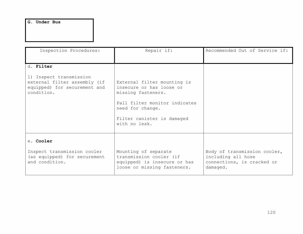
120
Inspection Procedures: Repair if: Recommended Out of Service if:
d. Filter
1) Inspect transmission
external filter assembly (if
equipped) for securement and
condition.
External filter mounting is
insecure or has loose or
missing fasteners.
Pall filter monitor indicates
need for change.
Filter canister is damaged
with no leak.
e. Cooler
Inspect transmission cooler
(as equipped) for securement
and condition.
Mounting of separate
transmission cooler (if
equipped) is insecure or has
loose or missing fasteners.
Body of transmission cooler,
including all hose
connections, is cracked or
damaged.
G. Under Bus
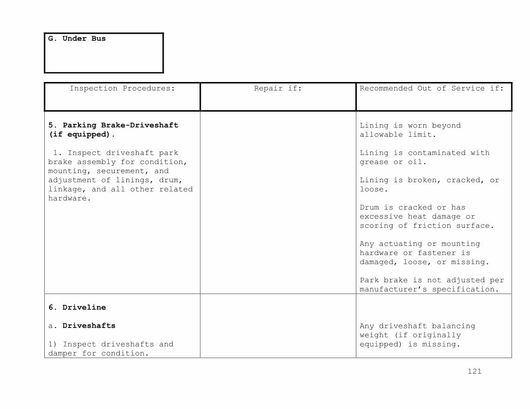
121
Inspection Procedures: Repair if: Recommended Out of Service if:
5. Parking Brake-Driveshaft
(if equipped).
1. Inspect driveshaft park
brake assembly for condition,
mounting, securement, and
adjustment of linings, drum,
linkage, and all other related
hardware.
Lining is worn beyond
allowable limit.
Lining is contaminated with
grease or oil.
Lining is broken, cracked, or
loose.
Drum is cracked or has
excessive heat damage or
scoring of friction surface.
Any actuating or mounting
hardware or fastener is
damaged, loose, or missing.
Park brake is not adjusted per
manufacturer’s specification.
6. Driveline
a. Driveshafts
1) Inspect driveshafts and
damper for condition.
Any driveshaft balancing
weight (if originally
equipped) is missing.
G. Under Bus
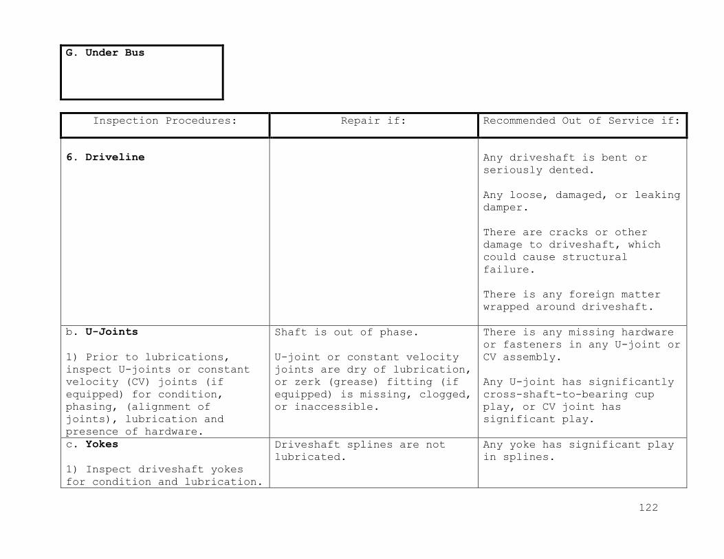
122
Inspection Procedures: Repair if: Recommended Out of Service if:
6. Driveline
Any driveshaft is bent or
seriously dented.
Any loose, damaged, or leaking
damper.
There are cracks or other
damage to driveshaft, which
could cause structural
failure.
There is any foreign matter
wrapped around driveshaft.
b. U-Joints
1) Prior to lubrications,
inspect U-joints or constant
velocity (CV) joints (if
equipped) for condition,
phasing, (alignment of
joints), lubrication and
presence of hardware.
Shaft is out of phase.
U-joint or constant velocity
joints are dry of lubrication,
or zerk (grease) fitting (if
equipped) is missing, clogged,
or inaccessible.
There is any missing hardware
or fasteners in any U-joint or
CV assembly.
Any U-joint has significantly
cross-shaft-to-bearing cup
play, or CV joint has
significant play.
c. Yokes
1) Inspect driveshaft yokes
for condition and lubrication.
Driveshaft splines are not
lubricated.
Any yoke has significant play
in splines.
G. Under Bus

123
Inspection Procedures: Repair if: Recommended Out of Service if:
6. Driveline
Dust cap on yoke is loose or
missing.
Zerk (grease) fitting is
missing or clogged.
Packing in dust cap is
missing.
Any yoke is cracked or
damaged.
d. Midshaft (midship) Bearing.
1) Inspect midshaft
(midship) bearings and rubber
insulators for condition and
securement.
Midshaft (midship) bearing
rubber insulator is
deteriorated, damaged, or oil
soaked.
Midshaft (midship) bearing
support is misaligned.
Bearing outer race is loose in
insulator, or inner race is
loose on shaft.
There is significant play in
midshaft (midship) bearing.
There is any missing or
damaged hardware or fastener
in midshaft (midship) bearing
or support assembly.
G. Under Bus
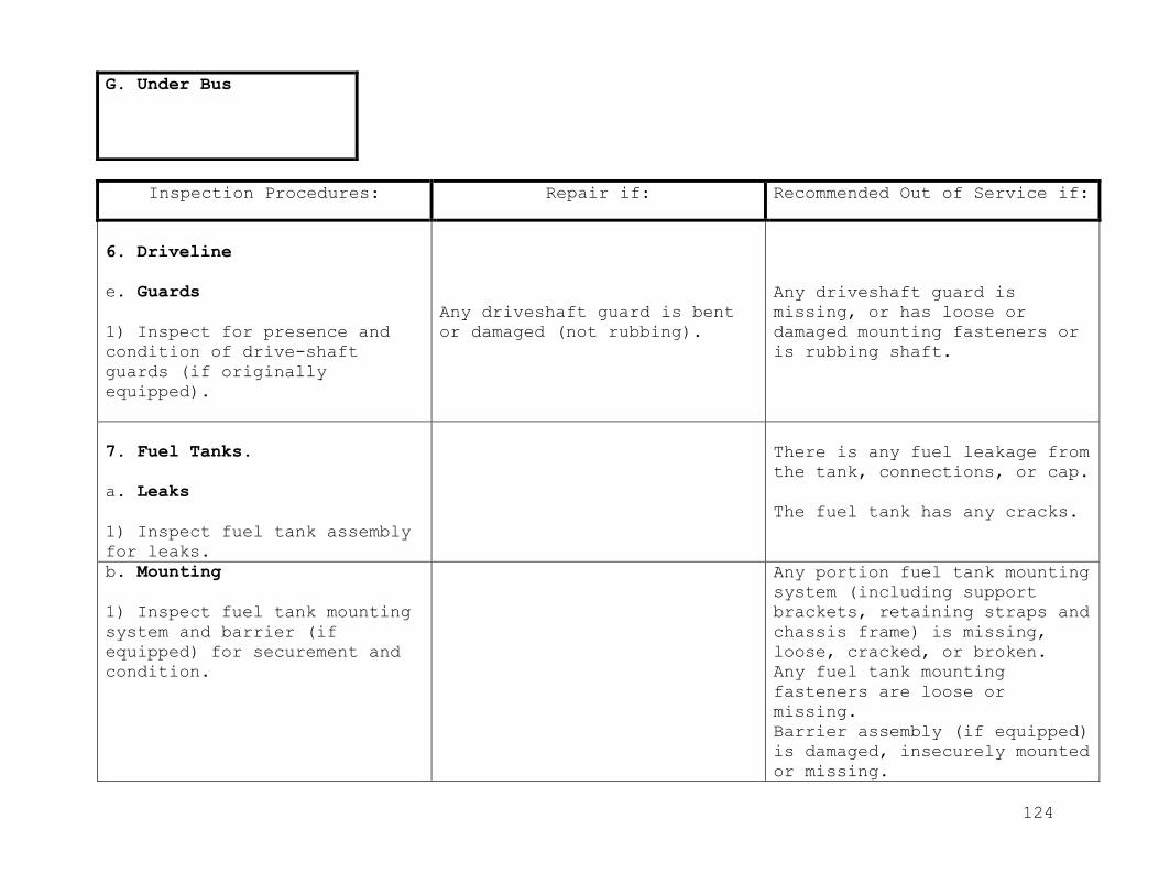
124
Inspection Procedures: Repair if: Recommended Out of Service if:
6. Driveline
e. Guards
1) Inspect for presence and
condition of drive-shaft
guards (if originally
equipped).
Any driveshaft guard is bent
or damaged (not rubbing).
Any driveshaft guard is
missing, or has loose or
damaged mounting fasteners or
is rubbing shaft.
7. Fuel Tanks.
a. Leaks
1) Inspect fuel tank assembly
for leaks.
There is any fuel leakage from
the tank, connections, or cap.
The fuel tank has any cracks.
b. Mounting
1) Inspect fuel tank mounting
system and barrier (if
equipped) for securement and
condition.
Any portion fuel tank mounting
system (including support
brackets, retaining straps and
chassis frame) is missing,
loose, cracked, or broken.
Any fuel tank mounting
fasteners are loose or
missing.
Barrier assembly (if equipped)
is damaged, insecurely mounted
or missing.
G. Under Bus

125
Inspection Procedures: Repair if: Recommended Out of Service if:
7. Fuel Tanks
Fuel tank is not O.E.M, been
modified or extra tank(s) have
been added.
c. Hoses
1) Inspect all fuel lines,
hoses and under bus fuel
system
components, for routing,
securement and condition
(including vents, fill and
crossover).
Any fuel line or hose is
unsecured or is routed subject
to excessive heat or abrasion.
Any fuel line or hose is
deteriorated or damaged
(including cracks or any
damage which may cause
potential leakage) or clamps
are loose or missing.
Any under-bus fuel system
filter, water separator or
other components are
insecurely mounted, cracked or
damaged.
d. Wiring
1) Inspect fuel tank sender
unit wiring for securement,
routing and condition.
Any portion of sending unit
wiring (including ground) or
connection is unsecured or
routed subject to excessive
heat or abrasion.
Any wiring or connection has
damaged or missing insulation.
G. Under Bus
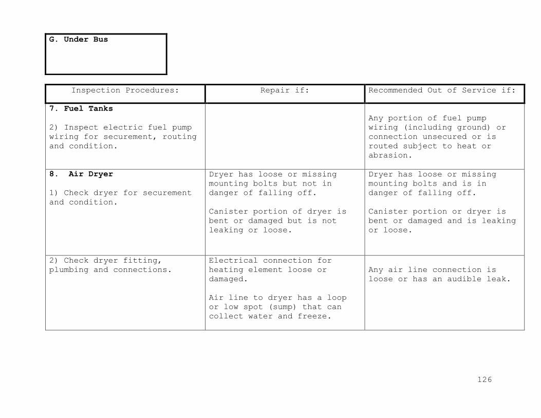
126
Inspection Procedures: Repair if: Recommended Out of Service if:
7. Fuel Tanks
2) Inspect electric fuel pump
wiring for securement, routing
and condition.
Any portion of fuel pump
wiring (including ground) or
connection unsecured or is
routed subject to heat or
abrasion.
8. Air Dryer
1) Check dryer for securement
and condition.
Dryer has loose or missing
mounting bolts but not in
danger of falling off.
Canister portion of dryer is
bent or damaged but is not
leaking or loose.
Dryer has loose or missing
mounting bolts and is in
danger of falling off.
Canister portion or dryer is
bent or damaged and is leaking
or loose.
2) Check dryer fitting,
plumbing and connections.
Electrical connection for
heating element loose or
damaged.
Air line to dryer has a loop
or low spot (sump) that can
collect water and freeze.
Any air line connection is
loose or has an audible leak.
G. Under Bus

127
Inspection Procedures: Repair if: Recommended Out of Service if:
8. Air Dryer.
3) Check purge valve for
operation and contamination.
Note: There may be dampness
and oil residue on and around
valve. A slight leak is
acceptable from valve during
charging cycle or if shut down
prior purge cycle.
Valve is contaminated by solid
material (desiccant, cloth,
rubber, metal, etc.), which
would prevent it from seating.
Valve continues to leak after
purge cycle.
9. Brake Chambers.
1) Inspect brake chamber
assembly(ies) for securement,
condition and proper size.
Any missing or damaged spring
brake caging bolts.
Any brake chamber mounting
bracket is cracked, bent or
broken.
Any brake chamber or mounting
fastener is damaged or loose.
Any brake chamber is not
original size or size of
chambers is not matched left
and right (Both sides same
size).
Any leak is detected in
chamber.
G. Under Bus
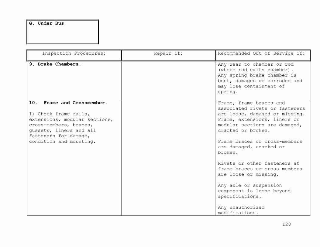
128
Inspection Procedures: Repair if: Recommended Out of Service if:
9. Brake Chambers.
Any wear to chamber or rod
(where rod exits chamber).
Any spring brake chamber is
bent, damaged or corroded and
may lose containment of
spring.
10. Frame and Crossmember.
1) Check frame rails,
extensions, modular sections,
cross-members, braces,
gussets, liners and all
fasteners for damage,
condition and mounting.
Frame, frame braces and
associated rivets or fasteners
are loose, damaged or missing.
Frame, extensions, liners or
modular sections are damaged,
cracked or broken.
Frame braces or cross-members
are damaged, cracked or
broken.
Rivets or other fasteners at
frame braces or cross members
are loose or missing.
Any axle or suspension
component is loose beyond
specifications.
Any unauthorized
modifications.
G. Under Bus
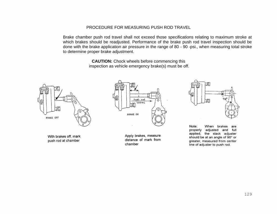
129
PROCEDURE FOR MEASURING PUSH ROD TRAVEL
Brake chamber push rod travel shall not exceed those specifications relating to maximum stroke at which brakes should be readjusted. Performance of the brake push rod travel inspection should be done with the brake application air pressure in the range of 80 - 90 -psi., when measuring total stroke to determine proper brake adjustment.
CAUTION: Chock wheels before commencing this
inspection as vehicle emergency brake(s) must be off.

130
Clamp Type Brake Chamber
(Dimensions in Inches)
Type Maximum Stroke
Maximum stroke with brakes adjusted
Maximum stroke at which Brakes should be adjusted
6 1-5/8 Should 1-1/4
9 1-3/4 be as 1-3/8
12 1-3/4 short as 1-3/8
16 2-1/4 possible 1-3/4
20 2-1/4 without 1-3/4
24 2-1/4 brakes 1-3/4
30 2-1/2 dragging 2
36 3 2-1/4

131
Rotor Chamber
(Dimensions in Inches)
9 2 Should 1-5/8
12 2 be as 1-5/8
16 2-1/2 short as 2
20 2-1/2 possible 2
24 2-1/2 without 2
30 3 brakes 2-1/2
36 3-1/2 dragging 2-3/4
50 4 3-1/4
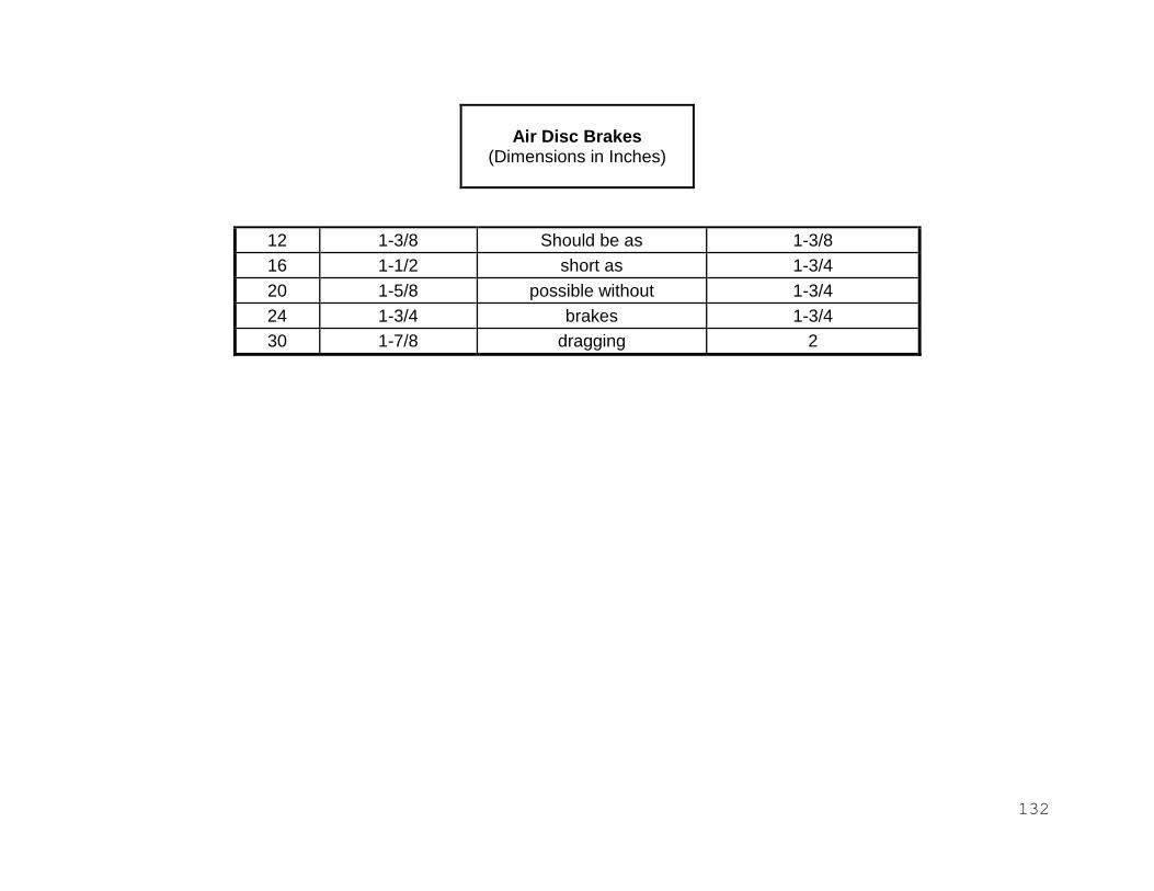
132
Air Disc Brakes
(Dimensions in Inches)
12 1-3/8 Should be as 1-3/8
16 1-1/2 short as 1-3/4
20 1-5/8 possible without 1-3/4
24 1-3/4 brakes 1-3/4
30 1-7/8 dragging 2

133
CHECKING BELT TENSION AFTER TIGHTENING Figure 1 - Checking Belt Tension Figure 2 -
Measuring Belt Tension Gauge Method Rule Method

134
Figure 3- Checking the rod and
Figure 4 - Checking Idler Movement
Drag link end movement
A. Movement in the axial direction must be less than 1/16 inch. B. Tie rod/drag link free to rotate
within steering arm socket. 1. Tie rod/drag link end 2. Steering arm

135
Figure 5
S-cam bushing up and down play S-cam bushing in and out play
Max .030” Up and Down

136

137
SECTION III
SHOP RECORDS AND INVENTORY CONTROL
Adequate record keeping is essential to a preventive maintenance program. Maintenance
records enable fleet management personnel to plan for and schedule needed maintenance
work. Accurate records may also be needed to support warranty claims or to provide
information for accident investigations. Even more important, well kept maintenance
records can be used by management personnel to monitor the maintenance program and
determine its effectiveness.
Among the documents to be included in a vehicle maintenance file are the mechanic’s
inspection and a copy of repair orders indicating the repairs performed and routine work
such as lubrication, oil, and filter change. The bus make, model, serial number, line
set ticket, and tire information should also be included. Records should be retained
according to the Library of Virginia’s General Schedules for Virginia Localities.
Sample forms included show information a school division should maintain on a school bus.
Work or repair orders are used to aid personnel in performing necessary repairs and
service and in providing adequate maintenance and cost records for each school bus. The
orders serve as a means of comparing parts used to parts in stock or purchased.
Retention of these orders makes it possible to maintain a complete history of all repairs
and service performed on each bus. The orders should contain all pertinent information
and be retained for the life of the bus. All labor costs must be included on repair
orders to provide accurate cost accounting.
Inventory records are essential in stocking items. These records also provide a means of
controlling inventory so as to ensure that parts are being used on authorized vehicles.
It is imperative that all items taken out of inventory appear on a repair order so that
they can be charged to the proper vehicle.
Today many school divisions are using automated systems to track maintenance and repairs
on school buses. These automated systems are encouraged and are used to track inventory
and other pertinent information about the school bus maintenance area.

138
Computer systems used for maintenance management can track valuable data and show any
trends regarding specific activities, including the following information, tracked by
both vehicle and by fleet:
Cost of repairs – parts and labor
Fuel consumption and fuel cost
Total operational cost
Historical data of inspection and repairs
Historical data of all expenditures
Bus data base by manufacturer, year, body type, etc.
Personnel information, timekeeping, payroll, etc.

139
School Bus Garage Repair Order
Division Year Date
Driver Model Mileage
Body Chassis Model
Acct Qty Part # Description Price Oper. No. Instructions Labor Charges
Gas Total Labor
Total Parts
Oil, Qts. Accessories
Gas, Oil, Grease
Grease, Lbs. Outside Repairs
Tax
Misc.
Total Total Total Amount

140
PARTS INVENTORY
PART NO. __________________________ DESCRIPTION _________________________
Cost ________________ Maximum Quantity ______________ Minimum Quantity _________
Date Doc. # On
Hand Date Doc. # On
Hand Date Doc. # On
Hand
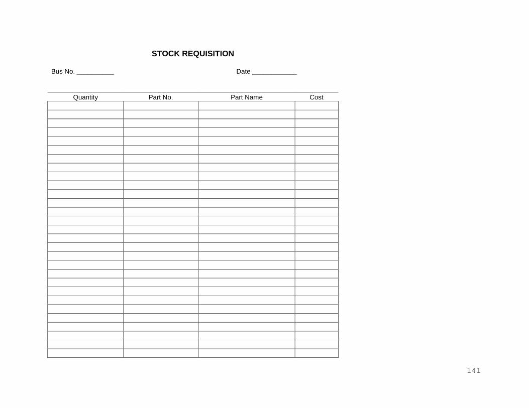
141
STOCK REQUISITION
Bus No. __________ Date ____________
Quantity Part No. Part Name Cost
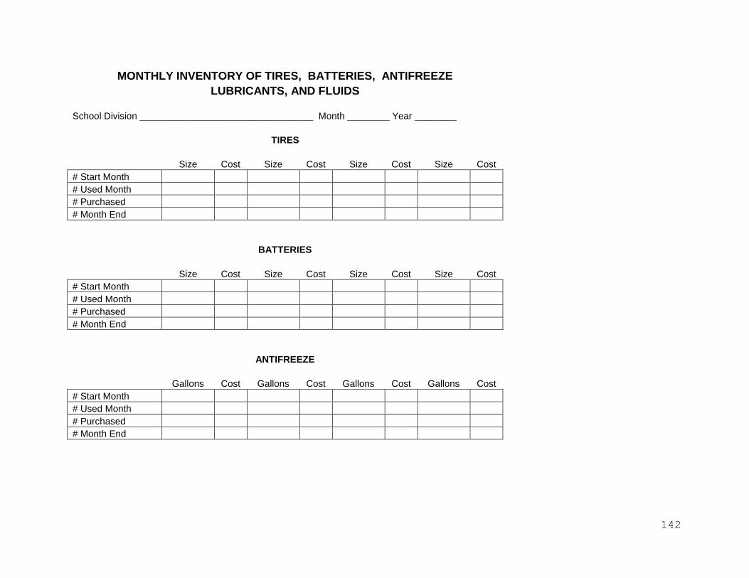
142
MONTHLY INVENTORY OF TIRES, BATTERIES, ANTIFREEZE
LUBRICANTS, AND FLUIDS
School Division _________________________________ Month ________ Year ________
TIRES
Size Cost Size Cost Size Cost Size Cost
# Start Month
# Used Month
# Purchased
# Month End
BATTERIES
Size Cost Size Cost Size Cost Size Cost
# Start Month
# Used Month
# Purchased
# Month End
ANTIFREEZE
Gallons Cost Gallons Cost Gallons Cost Gallons Cost
# Start Month
# Used Month
# Purchased
# Month End
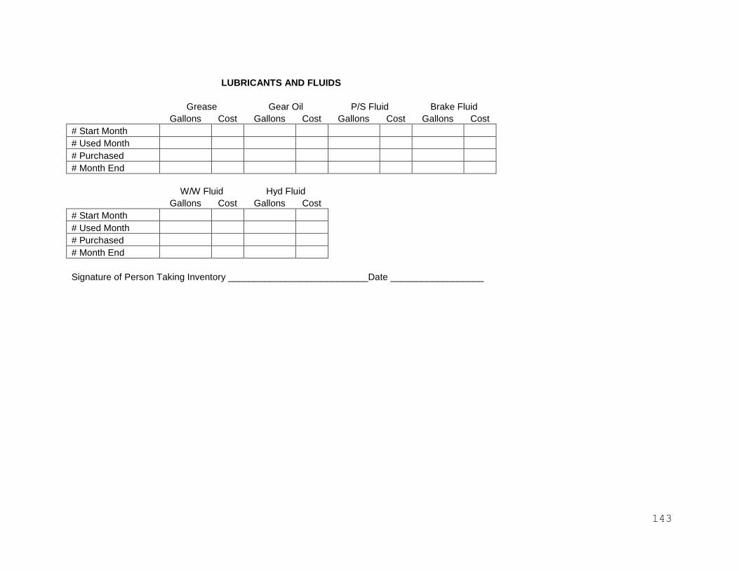
143
LUBRICANTS AND FLUIDS
Grease Gear Oil P/S Fluid Brake Fluid
Gallons Cost Gallons Cost Gallons Cost Gallons Cost
# Start Month
# Used Month
# Purchased
# Month End
W/W Fluid Hyd Fluid
Gallons Cost Gallons Cost
# Start Month
# Used Month
# Purchased
# Month End
Signature of Person Taking Inventory ___________________________Date __________________
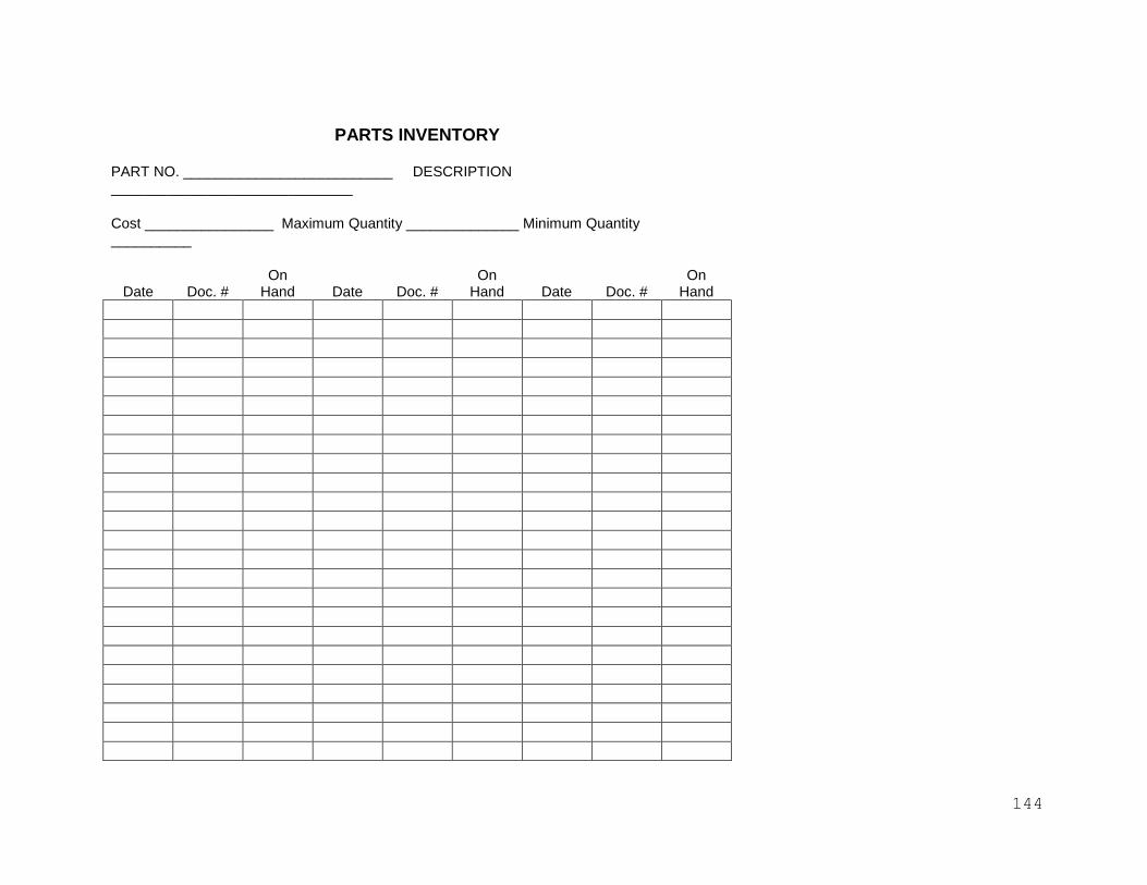
144
PARTS INVENTORY PART NO. __________________________ DESCRIPTION ______________________________
Cost ________________ Maximum Quantity ______________ Minimum Quantity __________
Date Doc. # On
Hand Date Doc. # On
Hand Date Doc. # On
Hand

145
Fuel and Motor Oil Report
Date _______________________________________ Location _____________________________________
Meter Reading - Start Meter Reading - End
Leaded Gasoline _____________________ Leaded Gasoline ________________________
Unleaded Gasoline _____________________ Unleaded Gasoline ________________________
Diesel Fuel ____________________ Diesel Fuel ________________________
Bus # Leaded Unleaded Diesel Fuel Motor Oil Odometer Remarks

146
Monthly Fuel and Motor Oil Report
Bus # _______________ Location _____________________________ Month End Odometer ___________
Driver _________________________________________________________ Month Start Odometer _________
For month of __________________________________, 20 ________ Total Mileage for month __________
Day Leaded Gas Unleaded Gas Diesel Fuel Motor Oil Odometer