The Potomac Yard Land Bay E · used on the project is a unitized curtain wall system that covers...
115
The Pennsylvania State University Department of Architectural Engineering Senior Thesis Drew Heilman Construction Management James Faust AE Senior Thesis Final Report April 7, 2010 The Potomac Yard Land Bay E Arlington, VA
Transcript of The Potomac Yard Land Bay E · used on the project is a unitized curtain wall system that covers...

T h e P e n n s y l v a n i a S t a t e U n i v e r s i t y D e p a r t m e n t o f A r c h i t e c t u r a l E n g i n e e r i n g S e n i o r T h e s i s
Drew Heilman Construction Management
James Faust AE Senior Thesis Final Report
April 7, 2010
The Potomac Yard Land Bay EArlington, VA

D R E W H E I L M A N - C O N S T R U C T I O N M A N A G E M E N T T H E P E N N S Y L V A N I A S T A T E U N I V E R S I T Y – D E P A R T M E N T O F A R C H I T E C T U R A L
E N G I N E E R I N G h t t p : / / w w w . e n g r . p s u . e d u / a e / t h e s i s / p o r t f o l i o s / 2 0 1 0 / d e h 5 0 2 2 / i n d e x . h t m l
THE POTOMAC YARD LAND BAY E ARLINGTON, VA
Contractor- James G. Davis Construction Owner- The Meridian Group Architect- Davis, Carter, Scott LTD. Civil Engineer- Christopher Consultants Structural Engineer- Smislova, Kehnemui &Assoc.MEP Engineer- Allen & Shariff Corporation Landscape Architect- Lewis Scully Gionet Delivery Method- Design-Bid-Build, GMPCost- $75 Million Duration- 20 Months, 1/2/2008 – 9/30/2009
Architecture:• Office Building • 9 Stories and a penthouse • Two Buildings – 369,300 SF • 235,000 SF Underground Parking Garage• Pre-Certified as LEED Gold • White TPO Roofing Membrane • Precast Building Façade • LA Fitness Facility • 1.35 Acre Site • Precast Wall Panels
Structural:• 5,000 PSI Formed Slab and Beams • 5” Thick Continuous Slab on Grade • All Foundation Concrete Minimum of 28
Days 5,000 PSI Compressive Strength • 12’-5” Typical Floor Height • Typical Bay Size 28’ x 34’ • 10” Concrete Roof Slab • Roof Structural Floor System is One-
Way Conventional Reinforced Concrete Slab
• Roof Supported by Shallow Wide Post Tension Concrete Beams
Mechanical:• (8) AHU Ranging from 16,400-20,400
CFM on 480/3 • (3) Cooling Towers Ranging from 5,970-
13,790lb Operating Weight • (2) 350 Ton Chillers • VAV used on Typical Floors to Regulate
Temperature• Fire Alarm System Rated for a Maximum
Working Pressure of 175 PSI • Utilization of Automatic Wet-type Class
I Standpipe Systems, Wet and Dry Type Sprinkler Systems
Electrical:• 277/480V, 3 Phase, 4W with 3,000A
Breaker Service to Both Buildings • (36) Lighting Fixtures throughout the
Buildings Operating on 277V or 120V • (10) Lighting Fixtures throughout the
Parking Levels Operating on 277V or 120V

Potomac Yard Land Bay E
Final Report 2
Table of Contents: 1. Thesis Abstract.....................................................................................................1 2. Acknowledgements..............................................................................................4 3. Executive Summary .............................................................................................5 4. Project Introduction .............................................................................................6 5. Project Team Overview .......................................................................................7
5.1. Client Information ........................................................................................7 5.2. Project Delivery Method...............................................................................7 5.3. Project Staffing Plan .....................................................................................9
6. Existing Conditions..............................................................................................11 6.1. Design Overview ..........................................................................................11 6.2. Building Systems Summary .........................................................................14 6.3. Local Conditions...........................................................................................14 6.4. Site Plan of Existing Conditions...................................................................15 6.5. Site Layout Planning.....................................................................................16
7. Project Logistics...................................................................................................18 7.1. Project Schedule Summary...........................................................................18 7.2. Detailed Project Schedule.............................................................................19 7.3. Project Cost Evaluation ................................................................................19 7.4. Detailed Structural Systems Estimate...........................................................22 7.5. General Conditions Estimate ........................................................................23
8. Proposal for Analyses ..........................................................................................25 9. Supplemental Energy (Electrical Breadth) ..........................................................26
9.1. Opportunity Statement..................................................................................26 9.2. Goal...............................................................................................................26 9.3. Methodology.................................................................................................26 9.4. Tools and Resources .....................................................................................26 9.5. Expected Outcome........................................................................................27 9.6. Research........................................................................................................27 9.7. Application ...................................................................................................29 9.8. Energy Comparison ......................................................................................29 9.9. Cost and Schedule Impacts...........................................................................36 9.10. Conclusions and Recommendations ...........................................................37
10. Solid Curtain Wall Implementation (Mechanical Breadth) .................................39 10.1. Opportunity Statement ................................................................................39 10.2. Goal.............................................................................................................39 10.3. Methodology ...............................................................................................39 10.4. Tools and Resources ...................................................................................39 10.5. Expected Outcome......................................................................................39 10.6. Research......................................................................................................40 10.7. Solar Heat Gain Comparison ......................................................................44 10.8. Cost and Schedule Impacts .........................................................................47 10.9. Conclusions and Recommendations ...........................................................49
11. Chilled Beam Implementation (Critical Industry Issue)......................................51

Potomac Yard Land Bay E
Final Report 3
11.1. Opportunity Statement ................................................................................51 11.2. Goal.............................................................................................................51 11.3. Methodology ...............................................................................................51 11.4. Tools and resources.....................................................................................52 11.5. Expected Outcome......................................................................................52 11.6. Research......................................................................................................52 11.7. Conditioned Air Volume and CIP Savings.................................................58 11.8. Cost and Schedule Impacts .........................................................................60 11.9. Conclusions and Recommendations ...........................................................63
12. Conclusions..........................................................................................................65 13. Work Cited...........................................................................................................66 14. Appendix..............................................................................................................67
A. Appendix........................................................................................................67 B. Appendix........................................................................................................68 C. Appendix........................................................................................................69 D. Appendix........................................................................................................70 E. Appendix........................................................................................................71 F. Appendix........................................................................................................72 G. Appendix........................................................................................................73 H. Appendix........................................................................................................74 I. Appendix........................................................................................................75 J. Appendix........................................................................................................76 K. Appendix........................................................................................................77 L. Appendix........................................................................................................78 M. Appendix........................................................................................................79 N. Appendix........................................................................................................80 O. Appendix........................................................................................................81

Potomac Yard Land Bay E
Final Report 4
2 Acknowledgements: Throughout my college career I have faced many challenges and accomplished many great things. Over the past five years I have grown both scholastically and socially by completing the Architectural Engineering curriculum. By pursuing this major at Penn State University I was able to meet and work with a variety of accomplished individuals both in industry and on the faculty. As my senior year nears the end I have many people to thank for their assistance in completing one of my final college milestones. I would like to thank the following for their help:
Penn State AE Faculty
• James Faust • Chris Magent • Robert Holland • Kevin Parfitt
James G. Davis Construction
• Bill Moyer • Steve Ghent • TJ Sterba • Nestor Santos
The Meridian Group
• Daniel Strotman
Solyndra
• Anthony Anello
TSI/ Exterior Wall Systems, Inc.
• Mike Callahan
Enclos Corporation
• Brian O’Connell
Arban & Carosi, Inc
• Nick Carosi IV
PACE Roundtable Industry Members

Potomac Yard Land Bay E
Final Report 5
3 Executive Summary: The 2009 PACE Roundtable event discussed many issues involving the current construction industry. Two important topics discussed during the event where sustainable construction and efficient project management. Today’s owners are looking for a building design that incorporates sustainable features to benefit there building throughout its lifespan and efficient construction methods to deliver projects on-time and on-budget. The following analyses intend to offer ideas on reducing building operating costs through energy savings and efficient construction through prefabricated materials.
The first analysis looks at the implementation of a Solyndra PV system on the existing white TPO roof of both buildings. Solyndra claims that the implementation of their product with a reflective roof will optimize energy production. The study shows that the proposed system will provide a savings of $38,650 during the first year after installation.When using a 5% cost of energy increase per year it was determined that the system will pay for itself with in 22 years of operation. This is within the 25-year warranty period, in fact, by the end of the warranty the owner will save $402,622.63 in energy costs.
The second analysis involves implementing a unitized curtain wall system in place of the existing architectural precast and punched window façade. This was proposed to shorten the schedule and provide more natural daylight to the interior space. This study showed that the total project schedule would be shortened by 23 days and reduces the general conditions by 1.75%. This translates into a savings of $106,701.30 for the project.However, it was determined that the curtain wall system would cost 31% higher than the existing system and would more than double the cooling load on the building by solar heat gain through the increased glazing. This would dramatically increase the energy cost placed upon this building because the glazing is one of the largest factors in the cooling load of an office building.
The third analysis incorporated replacing the current all air mechanical system with a more energy efficient chilled beam mechanical system. This analysis only involved the comparison between the distribution equipment and supply material. This analysis showed used the decreased ceiling plenum height to translate into savings for the building. From this analysis it was determined that by implementing this system the owner would save 52.7 CY of concrete, which translates to a $67,390.13 cost savings on CIP concrete for the structural columns. The owner would also save 5.22% of conditioned air volume in the building to allow for a higher percentage of ventilated air in the building. However, when comparing the duration of installation and initial cost the new system cost approximately 45% more to install and take 54% longer time to complete. Although the proposed system is projected to cost more and take longer to install than the current system typically, chilled beam mechanical systems have around a 23% yearly energy savings compared to an all air system. From these annual savings the average chilled beam system pays for itself with in 7-10 years of installation.

Potomac Yard Land Bay E
Final Report 6
4 Project Introduction: The Potomac Yard Land Bay E is a 369,000 square foot base building with a 235,000 square foot underground parking garage located next to US Route 1 and the George Washington Memorial Parkway in Arlington Virginia. Land Bay E is positioned near Reagan National Airport and south of Crystal City Virginia. The project is located on an old train yard that has been converted into commercial land development. Land Bay E sits on a 15-acre complex that is owned by The Meridian Group which houses a variety of buildings that range from hotel, office, residential and retail space.
Upon completion of the project it is to have achieved a LEED Gold Certification. The construction site is constrained to 1.35 acres and houses two tower cranes, two material hoists and management office trailer. The deliveries, excavation and construction are able to take place with out disturbing the surrounding traffic flow and operations.Construction on the project is projected to take 20 months beginning on January 2, 2008 and it’s scheduled to be completed by September 30, 2009.
The project includes new construction of a three level underground parking garage which will house 600 parking spots and two building towers that reach 9 stories of office space.The project also includes the construction of an outdoor interim space that consists of a landscaped park with a one-story building structure that will house either a small restaurant or a retail store. This space will fill the void between Land Bay E buildings East and West.
The building envelope of the Potomac Yard Land Bay E project consists of two types of systems. One of the systems is a curved curtain wall system and the other consists of architectural precast panels with punch windows. The other building envelope system used on the project is a unitized curtain wall system that covers the northern and southern facades of both towers. The southern façade of building B is covered with a curved curtain wall system that looks onto US RT.1. Other key features of the project include: the structural system consisting of cast in place concrete (CIP), courtyard area above portion of the parking garage, white TPO roofing and man high end finishes.
Figure 1: View from US Rte.1

Potomac Yard Land Bay E
Final Report 7
5 Project Team Overview:
5.1 Client Information:
The owner of the Potomac Yard Land Bay E buildings is The Meridian Group that is located in Bethesda Maryland. They are a large real estate and investment development firm that has complete over $2.8 billion in transactions. The Meridian Group maintains a focus on the Washington DC Metropolitan area and also has assets in Baltimore, MD, Charlotte, SC and West Palm Beach, FL. The company has successfully acquired over 7 million SF of industrial and office space and 439 acres since 1993. Property is acquired, structured, constructed, capitalized and managed by the Meridian Group. All of these qualities make this client very experienced with construction practices.
The Potomac Yard Land Bay E buildings are high-class office spaces with class-A materials to attract high-end tenants. On the plaza level of the eastern building there are a variety of special features catered to LA Fitness like basketball courts and other fitness rooms. On the P1 level of the western building there is a swimming pool, basketball court and more fitness club space. The Lobbies of the buildings boast elaborate wood and stone decorative wall and floor coverings. The elevators are covered in stainless steel and are illuminated with high-class lighting fixtures.
The owner for this project was concerned about many issues. Some of the issues that the concerned the owner was to make sure that they were obtaining a quality product for the best value. The owner was also concerned keeping the construction process on schedule without sacrificing safety. The schedule was very important to the owner of the Land Bay E project because the sooner the construction of the buildings were completed the sooner they could rent out the space and begin making money on their investment.Finally the materials that were used on the project were of concern to the owner because they wanted to house high-end clients in their buildings. For this reason they had selected higher end finishes to be installed throughout the buildings.
5.2 Project Delivery Systems:
The Potomac Yard Land Bay E Project has many key players in delivering this project successfully as shown in the previous project delivery diagram. On this project there is the owner, which is The Meridian Group that is based out of Bethesda, MD. The Meridian Group is constructing this project with a goal of renting it for mainly office space with the ground floor being a health club. As of now there are two tenants that are LA Fitness and Wachovia/ Wells Fargo Bank. The Land Bay E project is delivered as a design-bid-build with a negotiated GMP contract.
The general contractor on the Land Bay E project is James G. Davis Construction Corporation and the architect is Davis, Carter, Scott LTD. DCS LTD. has contracted several other firms to help with the design process. Christopher Consultants was hired to perform the civil engineering for the project and the site work design. The structural engineer hired for this job was a company based out of Fairfax, VA that was called

Potomac Yard Land Bay E
Final Report 8
Smislova, Kehnemui & Associates. The Allen and Shariff Corporation in charge of designing all of the mechanical, electrical and plumbing systems for the Land Bay E project and Lewis Scully Gionet was the landscape architect hired to design the finishes outside the building complex.
The subcontractors that DAVIS Construction used for the Land Bay E project were selected on a BAFO, best and final offer of the lowest offer with the comprehensive scope. DAVIS bonds all of the subcontractors over $150,000 for both payment and performance. For this project DAVIS did purchase liability insurance for work performed on the Land Bay E project. The main subcontractors that were selected for the project are listed below in figure 2.
Owner:
The Meridian Group
General Contractor: James G. Davis
Construction Corp.
Electrical Contractor: J.E. Richards
Plumbing & HVAC: W.E. Bowers &
Assoc.
CIP Concrete: Miller & Long Co., Inc.
Glazing: TSI/ Exterior Wall Systems, Inc.
Architect: Davis, Carter, Scott LTD.
Civil Engineer: ChristopherConsultants
Structural Engineer: Smislova, Kehnumui
& Assoc.
MEP Engineer: Allen & Shariff
Corporation
Landscape Architect: Lewis Scully Gionet
Figure 2: Project Delivery

Potomac Yard Land Bay E
Final Report 9
5.3 Project Staffing Plan:
James G. Davis Construction has placed both management and field members on the Land Bay E project to accommodate the size and scope of the project. Throughout the project the personnel needs to change in order to accommodate different stages of construction. During some stages of the project more personnel with a variety of expertise will be needed. Overall the project staffing structure looks similar to figure three shown below.
Assistant Project Manager:
The assistant project manager is responsible for posting and submitting RFIs and submittals. Also the APM is in charge of tracking change documents and shop drawings.
Assistant Superintendent:
The assistant superintendent is responsible for updating the schedule and dealing with subcontractors on a daily basis. The assistant superintendent is also in charge of helping with the site coordination.
Project Manager:
The project manager is responsible for the completion of his or her portion of the project.They must keep track of change orders, ticket items, make payments ensure that budget items are met.
Superintendent:
The superintendent is responsible for maintaining the schedule by making sure that the field labor is producing the required amount of work to complete the project on time.Additionally the superintendent is responsible for managing and coordinating the work force on the job site, preparing for deliveries and ensuring site safety.

Potomac Yard Land Bay E
Final Report 10
Figure 3: Project Staffing Chart
President & CEO: James Daivis
Vice President: James Dugan
Sr. Project Manager: Ben Apfellbaum
Project Manager: Meghan Callahan
APM: Robert Forbes
Project Manager: Scott Rhoades
APM: Steve Ghent
Sr. Layout Engineer: Mike
O'Neil
ProjectSuperintendent:Jim Keglovich
Superintendent:Fred Dandeneau
Assistant Super.: Andrew Fisher

Potomac Yard Land Bay E
Final Report 11
6 Existing Conditions
6.1 Design Overview:
Demolition:
The Potomac Yard Land Bay E project required no demolition because its prior use as a train yard. This site was relatively level with minimal structures. The project is one of many buildings that the owner is having built on their 15 acre facility. There has been previous construction on the 15-acre lot therefore making the Land Bay E site of 1.35 acres ready for construction to begin.
Structural Steel:
The Land Bay E project has minimal structural steel due to the fact that it is predominately a concrete structural system with post-tensioning elevated concrete slabs.The steel that is used in this project is cold-formed light steel that is used for some structural applications in the penthouse areas and also used for framing purposes. The structural steel studs on this project have minimum yield strengths of 50,000 psi for 16 gauge and thicker materials, and 33,000 psi for materials thinner than 16 gauge.
Cast In Place Concrete:
The Land Bay E project is mostly constructed with CIP concrete. It uses a variety of concrete strengths throughout the building. The building uses 5000 psi concrete for the slabs and beams, 4500 psi concrete for the slab on grade, 4000 psi concrete for the walls and piers, 5000 psi for the pile caps and 2500 psi concrete for CMU fill. All concrete ramps, parking levels, plaza levels and slabs shall have a minimum of 28 day curing time.
Figure 4: Existing Conditions

Potomac Yard Land Bay E
Final Report 12
All of the typical floors in the buildings are constructed of elevated post tension concrete slabs. All of the reinforcing steel being used on this project shall be deformed billet steel conforming to ASTM A615, Grade 60. For any of the reinforcing steel that is being used on the Land Bay E project that is exposed to the elements is coated with an epoxy coating to retard the degradation of the product. The concrete placement was completed by a variety of methods like crane and bucket, concrete pump and Georgia buggies by Miller and Long. There were two tower cranes used in this process of placing the concrete, each located in one tower.
Precast Concrete:
There are two types of precast concrete used on the Land Bay E project. One of the types is prestressed concrete that is used for structural purposes as the piles. The reason for the use of piles on this project is due to the surrounding soil types and the depth of the water table. This project is within a small distance of the water table thus requiring a different type of foundation and a dewatering system. The piles that are used on the Potomac Yard Land Bay E project are 14’x14’ that can resist 125 tons of force. These piles were driven into the ground to bear on natural soil which was on average about 30’ below the lowest floor. The other type of precast concrete that was utilized on this project was used for architectural purposes as seen in figure 5 above. These panels are used on the façade of the buildings and are designed to anchor onto the structural concrete frame. The precast panels must also resist a force of 6000 pounds and not fail.
Mechanical System:
The mechanical contractor involved on the Land Bay E project is W.E. Bowers and Associates. The mechanical system in the Land Bay E buildings consist of 8 AHUs, 3 cooling towers, 2 chillers, both wet and dry sprinkler systems and VAV units that operate on every floor to regulate the air temperature. Between the two towers of the Land Bay E project there are 9 elevators, 8 of which service all of the floors including the parking levels. The other elevator is a hydraulic elevator that sole purpose is to serve the LA Fitness center. In the parking levels there are two garage air intake shafts and two garage air exhaust shafts. The building houses mechanical rooms on all of the floors except for the two lower P-levels. The combine size of the penthouses for both of the buildings for
Figure 5: Architectural Precast

Potomac Yard Land Bay E
Final Report 13
the Land Bay E project total is 15,430 SF which house the (2) chillers, (3) cooling towers, (8) AHUs and chilled water pumps.
Electrical System:
The electrical contractors involved on the Land Bay E project are MCLA and J.E. Richards. The electrical system that serves both of the buildings of the Potomac Yard Land Bay E project consists of a 277/480V, phase, 4W with a 3000A breaker service.The main service to the buildings is brought inside on the north face of the building system on the P1 level. The main electrical room is situated on the P1 level near the loading dock. Throughout the project there are 36 different lighting fixtures in the buildings A and B and there are 10 different lighting fixtures that are installed throughout the P-levels.
Masonry:
The masonry in this project is strictly used for load bearing purposes. There is no brick or architectural stone usage on the buildings. The concrete masonry units used on this project are to be placed with type N mortar joints and type S mortar joints for exterior walls. The masonry cells in the buildings are to be filled continuously with grout and reinforced. Wall ties were also used when being connected to steel beams.
Curtain Wall:
A curtain wall system was used for the curved portion of building B’s façade and between both buildings A and B as seen in figure 6 below. On the larger portion of the project a precast architectural panel system with a punch out window glazing system would be put into place.
Support of Excavation:
The design and installation of support of excavation was required for the Land Bay E project due to the soil and water conditions. The site was supported by sheet piling system to protect against caving. The excavation supports were not removed from the
Figure 6: Curtain Wall System

Potomac Yard Land Bay E
Final Report 14
site until the structural system was braced. Once the excavation system was removed then proper backfilling of the site was completed.
LEED:
This project is projected to achieve a LEED certification of gold by the completion of the construction. There were many items that were used on the Land Bay E project that helped to achieve this status. Some of the materials and methods that were used on the project was a white TPO roofing membrane, recycling stations placed on every typical floor, recycling disposal service, additional bicycle racks added to the parking levels, local building materials and local transportation access. The reason that more bicycle racks were added is because of the large number of motor vehicle parking spots. Two contractors on this project provided the recycling service. The two contractors involved were American Disposal and Miller & Long/ NOVA. These two companies sorted land debris, asphalt, concrete and masonry, metals, drywall, wood, cardboard, paper, plastic and non-disposable materials. From this process there was 1,422.86 tons of recycled material and there was 93.94% of trash diverted from landfills.
6.2 Building Systems Summary:
Yes No Work Scope X Demolition X Structural Steel Frame
X Cast in Place ConcreteX Precast Concrete X Mechanical System X Electrical System X Masonry X Curtain Wall X Support of ExcavationTable 1: Buildings Systems Summary
6.3 Local Conditions:
Figure 7: Local Map Figure 8: DC Area Map

Potomac Yard Land Bay E
Final Report 15
The construction industry in the Washington DC metro areas is most commonly Cast in Place Concrete (CIP). To complete the structural system along with the CIP is most commonly post tension concrete slabs. The reason for the use of concrete structures in this area is due to the height restrictions placed within the District. Although these height restrictions do not apply to the surrounding cities this form of construction is highly adopted as a common practice. With the high demand for concrete structures in this area it limits the possibilities for steel erectors to become as profitable.
The project is located in an area of Arlington that predominately houses commercial office buildings along with some residential condos. Due to the condense area parking lots are at a minimum thus most buildings utilize parking decks and underground parking.Luckily during construction there is ample room on the northern portion of the sight for workers and management personnel to park outside the construction site. Although there is parking spots available it is appreciated that carpooling occur.
The type of projects that usually occur in the Washington DC metro area is predominately government buildings and related structures along with private office buildings. Being that Washington DC is the nation’s capitol there is a lot of large businesses in the surrounding area like BAE Systems, Northrupp Grumman and Innovative Defense Tech that require large scale sophisticated buildings. Along with big business are the tourist attractions all over the area both government and historically related like the Pentagon and the Washington Monument. Both of these businesses require hotels, retail, residential and office space which the National Gateway at Potomac Yard provides.
Currently in the country’s economic state of recovering from a recession there is unfortunately a reduced need for large office space. As of now there are two occupants that plan to move into the Land Bay E buildings. These two companies include LA Fitness and Wachovia/ Wells Fargo Bank. The rest of the building is currently awaiting occupancy.
The Potomac Yard site contains soft and compressible Stratum B1 soils that do not support the usage of shallow foundations like spread footings and mat slabs. Instead the use of deep foundations like precast concrete piles was recommended with a compressive strength of at least 4,000 psi. The piles are recommended to be of 30 feet in length below the lowest floor level. The water table was found to be at elevations of 0 to +15 feet thus the use of dewatering systems during construction were utilized. After construction pumping systems will still need to be used like sump pumps stations that are located in the lower P-levels.
6.4 Site Plan of Existing Conditions:
Please see Appendix A for site plan of existing conditions

Potomac Yard Land Bay E
Final Report 16
The Potomac Yard Land Bay E project is located in Arlington, VA along US Route 1 and Glebe Road. The Land Bay E West project is one of eight buildings that are part the Potomac Yard complex. Land Bay E has two buildings that border to the north, one to the east and one to the south. All of the buildings names are Land Bay with different letters A-F. The buildings that surround Land Bay E West range from a variety of uses that consist of residential, office, retail and hotel.
The existing utilities around the site were run on the south border of the site while the new utilities were brought in on the northern border. There are several new light poles that will be installed surrounding the building along with new walkways. Once the parking deck the parking was completed Center Park was installed on top.
6.5 Site Layout Planning:
Figure 9: Garage Layout
The Potomac Yard Land Bay E project utilized a deep foundation system that involved the use of 14”x14” precast concrete piles at a length of 35 feet. Theses piles were driven into the site starting in the northwest quadrant of the site working their way around in a counter-clockwise direction finishing in the northeast quad. In total there were 1011 piles that were driven into the site to provide a stable foundation for the structure. There were 17 different types of pile caps that were constructed on this project that ranged from different size, shape and thickness. These pile caps were used to transfer the load from the columns in the building to the piles that distribute the weight of the structure and occupants to stable ground. For the excavation process of the project a retaining wall made of soldier beams a lagging was utilized to retain the surrounding soil while the construction of the foundation and garage levels was commencing.
To gain access to the excavated portion of the site there were two ramps that were constructed, one in the SE quadrant of the site and the second is located in the NE quadrant of the site. For organizational purposes each of the ramps permit one-way traffic. To enter and exit the site you must go down the SE ramp and go up the NE ramp.The CIP concrete garage structure was placed in the same sequence as the piles and pile caps were placed which was starting in the NW quadrant and proceeding counter-clockwise finishing in the NE quadrant. Once the entire placement of the garage structure was completed the building structural system was able to begin.
Please see Appendix B

Potomac Yard Land Bay E
Final Report 17
Figure 10: Building Layout
The CIP concrete structure for Building B begins on December 8, 2008 on the southern portion of the project. The placement of the concrete is broken up into three sequences per floor. Tower Crane #1 performs the placement of the concrete for Building B. Once the placement of concrete and some heavy picks are completed Tower Crane #1 may begin disassembly around April 2009. The CIP concrete structure for Building A begins on December 29, 2008. This building will have three similar floor sequences for placing the concrete as performed on Building B. Finally once the placement of concrete is completed for Building A and the heavy equipment is set the disassembly of Tower Crane #2 may begin around May 2009.
Please see Appendix C

Potomac Yard Land Bay E
Final Report 18
7 Project Logistics
7.1 Project Schedule Summary:
Please see Appendix D for Project Schedule
The Land Bay E project was broken into three different phases. The three phases of the project were as follows: construction of the three parking levels, construction of building B and then the construction of building A. Although these three phases of construction started at separate times the work on all three of the phases was going on concurrently but at different stages.
Foundation Sequence
Due to the soil conditions and the site location’s water table, shallow foundations like spread footings could not be used. Instead precast concrete piles had to be used for the foundation of this structure. Due to the larger footprint of the underground parking garage, a large area needed to be excavated to install a soldier beam and lagging soil retainage system to keep the excavation from caving during the pile installation. Once this was completed the garage structure was ready to commence.
Structural Sequence
The structural sequencing of the project began with placing the cast in place columns for the parking levels and then placing the post tension concrete slabs for the parking decks.After the garage levels were completed the construction of building B began with the placing in the northern portion of the structure. Finally building A followed after building B started. Both of the buildings were having the concrete structure being placed simultaneously but at different stages.
Finish Sequence
After the structure of the buildings was completed the finishes could then proceed. Due to the fact that this project is just a base building and not a total interior fit out the buildings were not watertight when the core finishes begun. The reason for this is that
Figure 11: Foundation

Potomac Yard Land Bay E
Final Report 19
only the building cores like the bathrooms, janitor closets, mechanical and electrical rooms which are located in the center of the buildings could be completed because they are isolated from the outside conditions. When installing the finishes in these areas the rooms were supplied with conditioned air. The lobby areas were also having the finishes installed before the building was sealed. This required the use of temporary doors, walls, air barricades and dehumidifiers.
7.2 Detailed Project Schedule:
Description Date Begin Construction 1/2/08
Complete Foundation 9/24/08 Permanent Power 7/27/09 Garage Complete 9/11/09 Project Complete 9/30/09
Table 2: Important Dates
The Potomac Yard Land Bay E project began its preconstruction activities during the summer of 2007 laying out the key plan for what the project was to become. The general contractor on the project was James G. Davis Construction Corporation that began its preconstruction activities in July of 2007. Around late August 2007 the design team released their final construction set of drawings to general contractor and the owner.After all of the preconstruction activities were completed the construction for the Land Bay E project began on January 2, 2008.
The detailed project schedule for the Potomac Yard Land Bay E project includes both preconstruction and construction activities with more of an emphasis on the construction phases. The detailed project schedule breaks down the three different phases of the project in detail for each trade. The three phases of this project include the garage levels, building B and Building A. In these three phases include various sequences that the construction process follows to ensure an organized approach to building the project.
Each phase of the building project is broken down into detail about the structural systems installation, MEP rough-in and trim out, finishes and exterior site work. The structural system for the garage levels starts in late August 2008, the MEP installation begins in late October 2008 and the finishes begin in December 2008. Next on the schedule Building B begins it’s placing of structural concrete followed by the same sequence of events as the garage levels. After the structural concrete is placed for Building B, Building A begins its placement of structural concrete. While the placing of concrete is being completed for Building A the MEP work for Building B and the finishes for the garage levels is commencing simultaneously.
7.3 Project Cost Evaluation:
Cost Summary

Potomac Yard Land Bay E
Final Report 20
Potomac Yard Land Bay E Cost Cost/SF Construction Cost $69,646,805 $112.53Total Building Cost $76,558,826 $123.70Table 3: Construction and Building Cost
Building System Cost
Building System Cost Cost/SFCIP Concrete $15,700,000 $25.37Precast $2,570,000 $4.15 Glazing and Composite Panels $11,070,000 $17.89Elevators $2,222,427 $3.59 HVAC/ Plumbing $9,675,000 $15.63 Electrical $5,450,730 $8.81 Fire Protection $974,400 $1.57 Table 4: Building Systems
D4 Historical Data Estimate-
Please see Appendix E for D4 estimate sheets
Building Data
Name Size Floors Bldg. Cost Westchase Corporate Center 308,500 6 10,492,634Ha-Lo Headquarters 267,334 7 37,643,382Willow Oaks III 407,042 7 16,757,728Table 5: Building Data
Parking Garage Data
Name Size Floors Bldg. Cost Park Place Parking Garage 129,024 5 3,158,033 Parking Garage 144,000 5 4,492,052 Renaissance Parking Garage 301,000 10 18,288,595Mercy Health Parking Garage 220,000 4 6,581,720 Table 6: Parking Garage Data
When using D4 Cost Estimating Software for the Potomac Yard Land Bay E project the above projects where selected from the historical database. The reason for two estimates is because there were no projects that incorporated an underground parking garage with the building. The reason that the selected projects were used in the estimate is because they had the similar use, size and number of floors respectively. When obtaining the two estimates and adding them together to obtain the total project cost of $63,384,284. This total was about $13,174,542 short of the original project estimate.
RS Means Estimate-
Please see Appendix F for RS Means data sheets

Potomac Yard Land Bay E
Final Report 21
Building A Building B Parking Garage Perimeter 333 LF 298 LF 647 LF Square Footage 188,095 SF 181,997 SF 248,842 SF Floor Height 12.5’ 12.5’ 10’ Elevators 4 5 8 (used in bldgs)Table 7: SF Estimate
Building A
Base Unit Cost $148.81 Adjustment NotesStory Adjust .5 .69 Per 1Ft Perimeter Adjust 247.95 -7.35 Per 100LF Special Foundation .49 Elevators 0 Per Car Subtotal: 142.64 Location: .93 132.66 Arlington, VATable 8: Building A Adjustments
Total Bldg. Cost: $24,951,719.84
Building B
Base Unit Cost $149.18 Adjustment NotesStory Adjust .5 .69 Per 1Ft Perimeter Adjust 273.16 -8.40 Per 100LF Special Foundation .49 Elevators 1 3.66 Per Car Subtotal: 145.62 Location: .93 135.43 Arlington, VATable 9: Building B Adjustments
Total Bldg. Cost: $24,644,526.39
Parking Garage
Base Unit Cost $148.81 Adjustment NotesStory Adjust 0 0 Per 1Ft Perimeter Adjust 247.95 -3.96 Per 100LF Special Foundation .57 Elevators 0 Per Car Subtotal: 67.14 Location: .93 62.44 Arlington, VATable 10: Parking Garage Adjustments
Total Bldg. Cost: $15,537,744.25
Total Project Cost: $65,133,990.48

Potomac Yard Land Bay E
Final Report 22
Comparison between D4 and RS Means
When comparing the two estimates for the Potomac Yard Land Bay E project it was determined that they were both over $10 million short from the original estimate. The reasons that the estimates could be inaccurate from the real project cost is:
• The foundation piles that needed to be driven into solid earth may not have been taken into account.
• The projects were not quite the same as the Land Bay E project in the sense that the buildings were built on top of the parking garage.
• The dewatering during excavation and the dewatering systems needed for permanent usage may not have been taken into account.
• Location factors seem to be a little low considering it is so close to Washington DC it would seem that it should be closer to 1.0 and not .93 for Arlington, VA.
7.4 Detailed Structural Systems Estimate:
The structural system for the Potomac Yard Land Bay E project consists of a deep foundation, CIP columns, CIP slabs, CIP walls and post tension concrete beams. There is virtually no steel used on the project except for reinforcing purposes and architectural purposes. The places that the miscellaneous metals are used are on the metal trellises, canopy and the metal roofs on the mechanical rooms. The use of concrete as a structural system in this area is very common. Two tower cranes, pump and Georgia buggies completed the entire concrete placement on this project.
To perform the structural concrete estimate for this project it was broken it into seven categories which include: concrete piles, pile caps, floor slabs, concrete walls, columns, beams and cranes. The deep foundations consisted of concrete piles that were 14”x14” with a length of 35’. There were 17 pile caps that ranged in size, shape and depth. All of these conditions were taken into account to obtain a total cubic yard amount of concrete.The floor slabs varies in thickness, so to determine the total amount of concrete used in them the thickness was multiplied by the total area of the slabs. The total volume of concrete for the columns and beams was determined from the cross sectional area multiplied by the total length of the beam. The structural drawings were used to complete the concrete take off for all three parts of the project. Once the take off was completed the total structural estimate was determined by using the cost data provided by 2009 RS Means sources. Once the project total was achieved it was then multiplied by the .93 location factor for Arlington Virginia. After obtaining the adjusted total amount for the location of the project the cost per square foot was obtained by taking the total and dividing it by the total area of the project.

Potomac Yard Land Bay E
Final Report 23
Code Description Cost
31 62 13.23 Prestressed Piles $1,185,397.50
03 30 53.40 Pile Caps $769,587.00
03 30 53.40 Floor Slabs $9,420,722.00
03 30 53.40 Garage Walls $487,600.00
03 30 53.40 Columns $1,396890.00
03 30 53.40 Beams $5,029,752.00
01 54 19.50 (2)Cranes 12 Mo $2,737,500.00
Total: $21,027,448.50
Adjusted: $19,555,527.11
Cost/SF: $31.59
Table 11: Structural Summary
The total structural systems estimate came to $19,555,527.11 that is only about $1,285,854 over the estimate that was provided by the general contractor. This is only about 4.7% over the original estimate for the structural system of the project. The reason for the accuracy of the estimate could be due to the common building type of the project. RS Means may compare similar projects for cost data in the reference books. Another factor that helped the accuracy of estimate is that the structure is predominately made up of structural concrete instead of a variety of different structural materials.
7.5 General Conditions Estimate:
Total General Conditions $6,110,382.88
% Total Contract Value 7.98
Cost per Month $305,519.14
Cost per Week $71,050.96
Table 12: General Conditions Summary
Above is a summary of the General Conditions estimate for the Potomac Yard Land Bay E project. This summary takes into account for the project staff, permits, insurance, fee, construction facilities and equipment and temporary utilities. This estimate was prepared by using 2009 RS Means data and pricing along with the current industry unit costs provided by James G. Davis Construction Corporation. The largest portions of the General Conditions estimate are comprised from the project staff costs and the contractor’s fee. The general contractor’s project staff estimate was calculated by the industry rate for that position multiplied by the percentage of time a week the individual spent on the project. Some items that are normally included on a GC estimate like a

Potomac Yard Land Bay E
Final Report 24
crane and material hoist were not provided in this estimate because they were part of the subcontractor’s bid package.
Please see Appendix G for General Conditions Estimate

Potomac Yard Land Bay E
Final Report 25
8 Proposals for Analyses: The Potomac Yard Land Bay E project located in Arlington Virginia is currently striving to reach a LEED Gold certification upon its final completion. As the economy and needs of building owners have changed over the past decade, so has the way construction is being performed. Energy prices have increased dramatically over the past few years and are intended to rise even more. Building owners want to build buildings and occupy them as soon as possible. Having all of these changing conditions in the industry the main goals of new construction is to build faster, smarter and more energy efficient products.
The 2009 PACE Roundtable Event was focused on a variety of issues that include: a panel of industry members that discuss how the industry is changing due to the economic circumstances and stimulus package, a breakout session that involved a problem identification and solution development, and a student panel discussing the communication patterns of the Now Generation. The breakout sessions had three different topics to choose from to attend. The three topics that were offered this year were Energy and the Building Industry, BIM Execution Planning and Business Networking. From attending the Energy and the Building Industry session one could learn about new and exciting technologies that are being utilized in the industry today and lastly and to become more familiar with the direction the industry is moving involving LEED and its applications.
There are many reasons for concern regarding the commercial energy consumption with in the United States. Some of the main concerns involve the environment, deregulation for competition, developing nations, federal and state incentives, life cycle costs, marketing image and national security for energy independence. To reduce energy consumption in the United States many alternate forms of energy resources are being utilized like: wind, solar, geotherm, nuclear, wave/tidal and biomass fuel. On a building and construction scale many new technologies and systems are being implemented like:space age insulation, LED lighting, BAS systems, office interior systems, hydronic heating and cooling systems, reuse/ deconstruction of materials and combine heat and power peak response systems.
As previously stated the construction industry is striving to build smarter, faster and more energy efficient projects. In doing so many different technologies and methods are being implemented. The focus of these thesis analyses will incorporate the reduction of energy consumption by the use of supplemental energy sources, schedule acceleration by the use of a solid unitized curtain wall system and energy conservation by the implementation of a chilled beam mechanical system.

Potomac Yard Land Bay E
Final Report 26
9 Supplemental Energy (Electrical Breadth)
9.1 Opportunity Statement:
The United States is one of the world’s highest energy consumers for which over 50% of the country’s energy consumption is used by commercial buildings. The building industry is under much scrutiny to produce more energy efficient buildings in order to reduce the country’s energy consumption. In the United States there is approximately 30 billion square feet of commercial roof area that could be used for placement of supplemental solar energy harvesting. The Potomac Yard Land Bay E could utilize a solar collection system to supplement its energy consumption provided by the United States energy suppliers.
9.2 Goal:
By placing solar panel systems on the roof, which consists of a large area of unusable space, the commercial building energy consumption could be reduced. The current roof system that is utilized on the Potomac Yard Land Bay E project is a white TPO roofing membrane that is designed to reflect large amounts of the sun’s energy instead of transferring it into the building. By adding a supplemental solar panel system to the 43,800 SF roof of this building would result in optimum performance for harvesting energy and a reduction of energy consumption from nation’s energy supply. By performing this analysis a comparison of energy created by the PV system will be compared to the building’s total energy consumption and the energy cost savings will be determined.
9.3 Methodology:
• Contact a Solyndra representative to determine systems capabilities • Obtain information about applications on cool roofs • Look at other buildings with the Solydra application • Look at current construction documents for the roof of the Potomac Yard project
to determine the layout and how many panels may be used • Calculate the initial cost of material and installation • Calculate duration of installation • Calculate current energy load on the building
o Calculate mechanical equipment o Calculate lighting load o Calculate receptacle load
• Determine energy savings • Determine payback period • Draw conclusions and make recommendations concerning application
9.4 Tools and Resources:
• Solyndra website • Solyndra sales personnel • Construction documents

Potomac Yard Land Bay E
Final Report 27
• DAVIS project team • ASHRAE 90.1
9.5 Expected Outcome:
Solyndra PV panels are a very efficient design for harvesting the sun’s solar energy and converting it into a valuable resource for the building. The PV system should produce enough energy savings to payback the system’s initial cost within a reasonable amount of time. The structural impact caused from the PV system on the building should be minimal because the design of the anchoring system is very lightweight and easy to install. The reason for its lightweight frame is because of the shape of the panels. The panels consist of many long tubular shaped solar collectors that allow the air to flow around and between the arrays that reduces the amount of wind resistance. Another feature that the system possesses is that it is mounted horizontally, parallel with the roof’s surface, which would reduce the uplift affect. Maintenance walkways may need to be considered for access to clean the panels along with proper waterproofing around the roof penetrations for anchoring. The installation of these solar collectors should not impede the schedule of the project because they can be installed as other work on the building is progressing without interruption. All of these features and the enhancement of green technology image for the building will probably outweigh the initial cost and installation of the product.
9.6 Research:
The installation of Solyndra PV panels would add to the sustainable image of the Potomac Yard Land Bay E building and will help to reduce the energy consumption from the electric grid. Since this is a new technology of harvesting the sun’s energy from 360 degrees by absorbing direct, reflected and diffuse sunlight. This is made possible by installing the solar array on top of the existing white Thermo Plastic Olefin (TPO) roofing membrane.
The building orientation in regards to the sun’s path is very minimal in effecting the system’s energy production performance. In most cases when the system is used on a cool roof application the system is able to produce approximately 99% of the maximum power output regardless of the orientation.The wind performance of this system is also superior to a conventional PV system due to its lightweight design and natural gaps between the solar modules on the panels. This design allows the wind to pass under and between the units creating minimal uplift on the system.
Figure 12: Solyndra Cell Diagram

Potomac Yard Land Bay E
Final Report 28
There are many reasons to place a Solyndra PV system on cool roof application. When a Solyndra system is applied on a cool roof surface the power production of the PV system will be enhanced unlike a conventional flat-paneled system. The Solyndra system is very lightweight that will impose a minimal impact to the roof structure. An individual panel and mounting system will only place a force of 3.3 lb/ft^2 on the roof system. Solyndra panels do not require any anchoring devices, which results in no roof penetrations.Instead, a self-ballasting material holds down the system to the roofing membrane.Solyndra’s solar panels have been tested and certified for use in winds up to 130 MPH.Typically each panel is capable of producing 200 watts/hr when used on a cool roof.Each panel comes with a 25-year power warranty and a 5-year product warranty.Another advantage to placing a Solyndra PV system on a white roof application is the qualification for a 30% Investment Tax Credit (ITC) that may be applied to the roof cost.The 30% credit may be applied to all of the following:
• Installation labor • Reflective roof material • Fasteners and adhesive agents • Insulation• Supporting materials
When considering the implementation of the Solyndra PV system there are many advantages that can be factored while comparing to only one real disadvantage, the initial cost of the product. Many of the advantages include:
• High energy production • 30% ITC on cool roof with use of a Solyndra system • 25 year power warranty • No roof penetrations, self ballasted • Lightweight design • Superior wind performance • Flat angle installation, larger utilization of rooftop space • 3x faster installation • 50% reduction in installation cost
Figure 13: Solyndra vs. Conventional Wind Performance
Figure 14: Functioning Solyndra Panels

Potomac Yard Land Bay E
Final Report 29
9.7 Application:
When trying to apply the Solyndra PV system to the current roof of the Potomac Yard Land Bay E project the construction documents for the building and the product specifications for the PV system was referenced. The determination of how many Solyndra panels many fit on top of the rooftop could not simply be determined by taking the total roof area divided by the area of one panel. Because there is a mechanical penthouse and an architecture dome on each of the two towers the layout and number of panels had to be strategically place upon the rooftop of this project. When laying out the locations of the panels, considerations where made for access paths through the arrays for maintenance and cleaning. The average sizes of the pathways are around two feet in width. When layout the system on the roof of both towers of the building it was determined that 531 panels could be placed on the roof of building A and 499 panels could be place on building B. The total number of panels that could be used on this project is 1030.
9.8 Energy Comparison:
An energy comparison was conducted using the construction documents of the building and the product data supplied by Solyndra. In order to compare the energy consumption of the building to the energy production by the Solyndra PV system proposed for the roof, calculations involving the electrical and mechanical equipment were performed. To determine the power consumption for the building’s mechanical equipment the mechanical schedules were utilized to determine the total kilowatt-hours consumed per year by the equipment. For those pieces of equipment that were rated in horsepower a conversion of 745.7 watts = 1 HP was used to determine the amount of kilowatts consumed. To determine the energy cost for each piece of equipment the following was used:
Figure15: Solyndra Mounting Bracket Figure16: Solyndra Panel Spacing

Potomac Yard Land Bay E
Final Report 30
• 261 work-days in 2010 • 16 hours/day operation • 4176 hours per work year • Avg. Energy cost Balt. Wash. 2009: $.137/KWH
http://www.bls.gov/ro3/apwb.htm
Table 13: P-Levels Mechanical Power

Potomac Yard Land Bay E
Final Report 31
Table 14: Building A Mechanical Power

Potomac Yard Land Bay E
Final Report 32
Table 15: Building B Mechanical Power

Potomac Yard Land Bay E
Final Report 33
Table x16: Mechanical Equipment Total
The Potomac Yard Land Bay E project is currently a base building that consists of a core and shell construction. This means that the final building’s occupants have not been determined yet, which makes the current lighting and receptacle load unreasonable for accurate energy consumption. So in order to accurately represent the lighting load for the occupied building in its intended use the Lighting Power Density from ASHRAE 90.1 was used to determine the maximum lighting load. The LPD is an estimate of the W/ft^2 for a typical occupied space, so in order to determine the amount energy used in the building the LPD was multiplied by the floor area. To determine the energy cost of the lighting system the following was used:
• 261 work-days in 2010 • 10 hours/day operation • 2610 hours per work year • Avg. Energy cost Balt. Wash. 2009: $.137/KWH
http://www.bls.gov/ro3/apwb.htm
Table 17: Lighting Power Density
Table 18: Lighting Cost

Potomac Yard Land Bay E
Final Report 34
Please See Appendix H for LPD
When determining the receptacle load on the building the following was used:
• Add up all receptacles in the building • Sum volt*amps • Duplex receptacle = 180VA • Double duplex = 360VA • 1VA = 1 Watt • NEC 2008 Table 20.44 Article 220: Branch Circuit-Feeder & Service
o 1st 10 KVA – 100% o After 10 KVA – 50%
• 261 work-days in 2010 • 10 hours/day operation • 2610 hours per work year • Avg. Energy cost Balt. Wash. 2009: $.137/KWH
http://www.bls.gov/ro3/apwb.htm
Table 19: Receptacle Load
Table 20: Receptacle Cost

Potomac Yard Land Bay E
Final Report 35
Table 21: Energy Consumption
After determining the building’s total energy consumption per year the total energy production from the Solyndra PV system was calculated. In order to determine the amount of energy each panel can produce the insolation value for the Arlington Virginia area was referenced. Insolation is the amount of solar radiation that is absorbed in a given surface area over a certain amount of time. This value is typically expressed in KWH/m^2 per day. This value may also be known as the Earth’s solar irradiance at a given location on the planet. This value is measured by the direct absorption perpendicular to the surface. This value changes throughout the year due to the angle of the sun, distance from the sun and disruptions in the atmosphere like: dirt particulates, clouds, moisture content and other impurities.
In order to determine the power output for each panel for a year the number of sun hours per day must be used. The insolaton value is equal to the number of sun hours per day that the panel can absorb, so in order to determine the power output for each panel the number of sun hours for each month must be multiplied by the number of days in that month and the power rating for a panel. Finally to determine the percentage of total power output for the system, the application conditions must be considered. For this project the system is being implemented on a white TPO roofing membrane, which has a reflectivity of 88%. When comparing the reflectivity to the Solyndra Energy Yield chart, the energy yield for the system should be 99% of the optimum production.
Please see Appendix I for Reflectivity vs. Annual Energy Yield chart
Table 22: GAISMA Insolaton

Potomac Yard Land Bay E
Final Report 36
Once both the building consumption and Solyndra production was determined the energy savings could be found by comparing the two values. With the installation of this type of PV system the Potomac Yard Land Bay E building could have an annual energy savings of 1.38% that translates into a $38,650 savings for the first year. When deciding whether or not to install a supplemental energy system of this size an owner would most likely like to know how many years it will take for the system to pay for itself. To determine the payback period of the Solyndra system the initial cost of the system must be determined. The cost and installation of each panel was determined by pricing information that was provided by a representative of Solyndra. Each panel was found to cost approximately $1,400 installed. The roof of the project can accommodate 1030 panels. The total cost of the system for the Potomac Yard is approximately $1,442,00and would take about 22 years for 100% payback. The payback was determined by a 5% energy cost increase annually. It was determined that by year 25, the end of the warranty period, the system would have saved the owner $402,622.63 in energy costs.
Please see Appendix J for Solyndra Payback
9.9 Cost and Schedule Impacts:
The installation of this system should not interfere with any of the other construction activities on the project. This system may begin its installation after the roofing contractor has finished placing the roofing membrane. Once the roofing is completed installation technicians may bring the necessary materials on the rooftop to begin the panel set up. The panels are packaged in small, lightweight and easy to maneuver crates.All of the other rack connectors and tools used for installation are minimal because the supports simply snap onto the outer edge of the panel.
The mechanical installation process is fast and simple and includes:
• Connect the mounting hardware to the solar collector • Transport the panel to the desired location on roof • Plug in the DC connectors and the grounding cable • Install lateral clip to connect all panels • Place ballast material on mounting hardware
The mechanical installation of this system on the Potomac Yard Land Bay E project would be faster than the electrical installation. The mechanical installation of the panels on the rooftop would take approximately five qualified workers two eight-hour days.This includes delivery, setup and electrical connections for the panels for the electrician to connect to the building.
The electrical installation for this system is slightly more complex and would take a little longer than the panel installation. Typically the electrician on the project, J.E. Richards, can perform the electrical installation and connection of the panels to the building’s electrical system. Normally it would take approximately two men five to ten working days to run the wire and install the switching mechanisms and inverter to convert the DC power to AC power. All of these activities may take place without interrupting the progress of the other construction activities.

Potomac Yard Land Bay E
Final Report 37
As previously mentioned the owner will incur a large initial cost by implementing the use of the Solyndra system. Each panel costs approximately $1,400 dollars including installation and the roof of the building can support 1,030 Solyndra panels. The total cost of implementing this system on the Potomac Yard project would come in at approximately $1,442,000. Although the system is quite pricey upfront it does however generate good returns, which is $38,650 for the first year with energy prices at $.137kWh.
9.10 Conclusions and Recommendations:
While conducting research for this analysis many sources and project archives have showed that the Solyndra solar collection system is the most efficient way of harvesting the sun’s solar energy. The logic behind the way this system works makes perfect sense.By using a highly reflective roof surface and the Solyndra PV panels the sun’s energy is to be harvested from 360 degrees. By absorbing the sun’s energy from all directions instead of a single angle would make sense that the system would produce a great amount of supplemental energy for the building.
Before the owner or a representative of the owner for the Potomac Yard project could make a decision on whether or not to implement the system or not they would have to look at some cost and system data. Although the owner probably would not be too willing to pay nearly $1.5 million dollars up front for a system that is fairly new, other factors need to be considered. The owner would want to look at the payback period, benefits, savings and marketability.
When looking at the payback period of the system the owner may think that 22 years is a long time for the system to pay for itself, but it will have paid for itself before the 25-year warranty has expired. By the end of the 25-year warranty the owner would have saved $402,622.63 on energy costs. Another consideration would be that yes the company receives a lot of positive publicity but they have only been in business since 2005. The question would then be how long would this system last, long enough to pay for itself.Although there are some definite concerns about installing such a new system as a long-term investment however, there are far more advantages to owning this wonderful technology. Some of the advantages that would probably peek the owner’s interest is:
• High energy production • 30% ITC on cool roof with use of a Solyndra system • 25 year power warranty • No roof penetrations, self ballasted • Lightweight design • Superior wind performance, tested and certified for up to 130 MPH • Flat angle installation, larger utilization of rooftop space • 3x faster installation • 50% reduction in installation cost • Marketability• Annual energy savings of $38,650

Potomac Yard Land Bay E
Final Report 38
After performing this study of the Solyndra PV system I would recommend this system to the owner of the Potomac Yard Land Bay E project however, the application of this system would be better suited for low rise buildings with a large amount of flat roof area.The reason for this is because there would be much more roof area for the panels to produce energy in comparison to the occupiable space of the building, which would result in a much faster payback period. There are many reasons why the implementation of this system would benefit the building and the owner. For instance the system would help enhance green image for the public and make the building more environmentally friendly. This could increase the marketability to introduce new clients or higher rent for the office space. Also by installing this product the owner would benefit from being part of a cutting edge technology that will more than likely become even more popular in the future. Lastly, the owner will be proud to know that they are helping the energy crisis by reducing the demand for the burning of fossil fuels in order to support the energy needs of the country.

Potomac Yard Land Bay E
Final Report 39
10 Solid Curtain Wall Implementation
10.1 Opportunity Statement:
The current building envelope system used on the Potomac Yard Land Bay E project consists of both an architectural precast façade with punched windows along with a curved curtain wall system on the ends of the buildings. Using two different types of building envelope systems for a project causes delivery issues and site congestion while storing the variety of materials before use on the building. By switching to a single building envelope system the duration of installation for the building may become shorter due to the repetitive activities and familiarity of connections. A reoccurring trend in the construction industry is the usage of prefabricated materials. By changing the building envelope for the Potomac Yard from two systems to a single glass curtain wall system that consists of prefabricated glazed panels would help speed up construction. This would help to reduce the use of varying materials that would speed up the installation period for the building envelope thus reducing the total project schedule.
10.2 Goal:
There will be many advantages to changing the building envelope from architectural precast and punched windows to a solid unitized curtain wall system. It will be determined how much shorter the project schedule may be reduced by implementing this type of building envelope system. By implementing this system the building’s occupants should receive more natural daylight into their workspaces.
10.3 Methodology:
• Contact a window and glazing contractor • Determine benefits of a solid curtain wall system • Run calculations for the increased solar gain on the building • Determine cost for curtain wall system • Compare cost of curtain wall system to original • Determine installation duration for curtain wall system • Compare durations for schedule impact • Explore methods of installation • Draw conclusions and make recommendations concerning application
10.4 Tools and Resources:
• Construction documents• Enclos and TSI project managers• DAVIS project team• Viracon website for product data
10.5 Expected Outcome:
The proposed curtain wall system would most likely reduce the schedule of the project because of the standardized use of materials and connections for the building envelope,

Potomac Yard Land Bay E
Final Report 40
prefabricated panels, placing methods and repetition of anchoring. The prefabricated panels will eliminate on site assembly and will just involve lifting and securing the materials on the building façade. If the monorail or floor crane system is chosen the site will become less congested and will allow for the curtain wall to begin installation before the structure is topped out and will allow for early removal of the tower cranes. While reducing the site congestion the typical floor will likely become crowded with panel layout. The floor staging will have to be considered because it may impede some ceiling work from being performed.
Other positive outcomes that may arise from switching to the curtain wall system will be the increased amount of natural daylight that enters into the typical floor space because of the floor to ceiling glazing which may result in higher rent for the owner. It has been proven that employees that work in conditions with increased amount of nature daylight have a positive effect on productivity. Along with the increased natural daylight in the building includes an increased amount of solar gain. The consideration of the increased cooling load on the building will also have to be considered because of the likelihood of it increasing.
10.6 Research:
Curtain Wall-
Curtain wall systems are becoming very popular for office building envelopes in today’s society. The main purpose for a curtain wall system is to keep the outdoor weather conditions out of the interior space of a building. Curtain wall systems are lightweight designs that provide absolutely no structural support to the building it is covering. This type of building envelope system typically spans multiple floors that increases the efficiency of installation and seals the entire building not allowing for any opening sections unless infill windows are implemented. A curtain wall system is typically connected to the building structure through either the columns or floor slabs. Typically curtain wall systems are made up of predominantly glass that is supported by an extruded aluminum framing system. The framing system contains components of seals, rails, mullions and connections to the structure.
There are many advantages that a curtain wall system offers to a building and its occupants. However, despite all of the advantages that the system provides strong consideration concerning the increased amount of solar heat gain must be address. This topic will be analyzed further in this analysis. Many of the advantages of a curtain wall system include the following:
• Architects can make curtain wall systems aesthetically pleasing depending on design
• Natural day lighting increase • Units assembled in factor controlled conditions • Units contain all necessary parts • Does not require external access for installation • Speeds up construction • Various outer coatings available

Potomac Yard Land Bay E
Final Report 41
• Units package in easily maneuverable crates
Installation of a curtain wall system typically can be performed pretty efficiently.Normally the preparation of installing the connections into the floor system or columns of the building takes a long time. After all of the preparation for the units is completed the installation process is able to begin and become very efficient as the activity progresses.There are four common methods used when installing a curtain wall system on a building that include, floor crane, monorail system, mobile crane and tower crane. The use of a tower crane is convenient because the device is already set up and ready for use however, in most cases it is being used for many other activities like topping out the building or lifting other heavy pieces of equipment into position. The problem with using a tower crane to install a curtain wall system is that it makes it more difficult to overlap other activities that involve the use of the crane, which will prolong the duration of the project.When using a crawler crane or a hydraulic rubber tired crane to install a curtain wall system the subcontractor must be concerned about several variables:
• Site congestion • Staging from the ground • Leveling• Cost, operator and rental • Transportation permits
A monorail system is another typical means of installation for a curtain wall system. A monorail system typically helps to speed up the process of installing the units over a crane because there is no time needed for repositioning. This system is made up of several parts, which include a lifting mechanism, tubular channels mounted to the roof structure and a means of attachment. When using this system the contractor does not have to worry about site congestion because the units are staged from their corresponding floor location. Typically the units are lifted into position from the floor that they will be covering by the monorail system above on the roof. As the installation progresses across the building’s façade the lifting mechanism is easily moved along the roof by means of the tubular channels. There are also many other factors that must be considered while using this installation method:
• Reinforcement of roof structure for mounting of cantilever brackets • Connection of lifting mechanism to rails • Distance between work area and lifting mechanism • Not affected by wind • Work multiple elevations at once • Not weather dependent
The last typical installation device used for a curtain wall system is a floor crane. This is a very common installation method among contractors because they are easy to use, not very expensive, easy set up and are very maneuverable. This mechanism is much like an engine hoist. It consists of a wheeled base structure that is able to support the overhanging weight of the curtain wall
Figure x: Floor Crane 1
Potomac Yard Land Bay E
Final Report 42
unit, a movable boom and lifting device that typically uses an electrical motor and steel cable. This type of mechanism is the preferred choice for installation of curtain wall units for both companies interviewed for this analysis. The typical sequence of installing a panel using a floor crane includes distributing the crates of units on the corresponding floor, setting up the crane two floors above the installation area, placing a unit on a wheeled cart in order to move to slab edge, attach lifting mechanism, slide out and lift into position and finally secure to connection.
The proposed curtain wall system for the Potomac Yard Land Bay E project would utilize a Viracon glazing system that comes with a 20-year warranty. Despite the generous warranty duration for the product there are still some cleaning and maintenance considerations that need to be noted. The curtain wall glazing must be cleaned inside and out frequently in order to maintain clear visibility. The aluminum rails and mullions must be cleaned upon the owner’s request. If the aluminum is coated with a powder coating or some other protective covering cleaning may not need to be performed. All seals and gaskets should be examined during frequent cleanings for areas of possible water penetration. After approximately 20 years all seals including the perimeter seals, glazing seals and gaskets should be replaced. Removal and replacement of all sealant devices involve the use of proper tools and skills to ensure optimum performance from the product.
Heat Gain-
Space heat gain is the rate at which heat enters into or is generated within a space at a given period of time. There are several ways in which heat may enter a space:
• Solar radiation through glazing • Heat conduction through interior partitions • Heat conduction through exterior walls and roof • Heat generated within the space by occupants, lights, appliances, and equipment • Loads as a result of ventilation and infiltration of outdoor air
There are two types of heat gain that include sensible and latent. Sensible heat gain is the energy added to the space by conduction, convection and radiation. Sensible heat load can be attributed to by the following:
• Heat transmitted thru floors, ceilings and walls • Occupant’s body heat • Appliance and light heat • Solar heat gain thru glass • Infiltration of outside air • Air introduced by ventilation
Latent heat gain is the energy added to the space when moisture is added to the space by means of vapor emitted by the occupants, generated by a process or through air infiltration from outside or adjacent areas. Latent heat load can be attributed to by the following:
• Moisture from outside air thru infiltration and ventilation

Potomac Yard Land Bay E
Final Report 43
• Occupant respiration and activities • Moisture from equipment and appliances
Total window heat gain = solar heat gain + conduction heat gain
Cooling Load-
Space cooling load is the rate at which energy must be removed from a space to maintain a constant space air temperature. The building’s total cooling load consists of both internal and external loads. External loads consist of those that are transferred through the building envelope while internal loads are the loads that are generated by the building’s occupants, equipment and lights. Space heat gain differs from space cooling load because the heat received from the sources described does not always immediately go into heating the interior space. For example during the day the sun’s solar radiation transfers through the windows of the building heating the surrounding materials and when the sun goes down the energy absorbed throughout the day in those materials is still releasing heat into the space.
CLTD/SCL/CLF Method-
In order to determine the total solar heat gain from the proposed curtain wall system and compare it to the original precast and punched window system the CLTD/SCL/CLF method will be utilized. This method stands for Cooling Load Temperature Difference/Solar Cooling Load/Cooling Load Factor Method. This is a hand calculation method that takes into account the lag-time in conductive heat gain through opaque exterior surfaces and the time delay by thermal storage in converting radiant heat gain to cooling load. This approach allows the calculation of the cooling load to be calculated by using the three factors CLTD, CLF and SCL. CLTD factors are used to adjust for the conductive heat gains, or external loads from the building envelope. CLF factors are used to adjust for the heat gains form the internal loads of the building. SCL factors are used to adjust the transmission heat gains from the glazing. The following steps will be used to calculate the solar and conductive heat gain through the glazing on the east and west building facades.
Conductive:
Q = U A *CLTD
1. Determine U – Value 2. Select CLTD for time of interest (Ch. 28 ASHRAE Table 34) 3. Corrections:
CLTD = [CLTD + (78-TR) + (TM-85)] Where
• (78-TR) = indoor design temp corr. • (TM-85) = outdoor design temp corr. • TR = Indoor room temp • TM = Mean outdoor temp • Tmax = Maximum outdoor temp • TM = Tmax-(Daily Range)/2

Potomac Yard Land Bay E
Final Report 44
4. Calculate glass area (A) from architectural plans 5. Q = U A *CLTD
Solar:
Q = A* (SC) * (SCL)
1. Determine shading coefficient (SC) from Viracon data sheet 2. Determine zone type from ASHRAE 1997 CH. 28, Table 35 B 3. Determine solar cooling load factor (SCL) from ASHRAE 1997 CH. 28, Table 36 4. Calculate glass area (A) from architectural plans 5. Q = A* (SC) * (SCL)
10.7 Solar Heat Gain Comparison:
In order to complete this analysis many values for computation were referenced in the 1997 ASHRAE Handbook Fundamentals I-P Edition. The following will be the method of determining the comparison of heat gain through the glazing of one side of the building. All of the other sides of the building will be shown in a summary at the end of the analysis. This analysis is strictly analyzing the solar heat gain through the glazing of the building during a 24-hour period. All other factors that affect heat gain are assumed to be constant like equipment, lighting, occupants, ect… At the end of the analysis a summary of the total difference in heat gained in a 24-hour period due to the change of building envelope will be given as a comparison of the total difference in cooling load upon the building. The weather data for Arlington Virginia was provided by Weatherbase.com and is as follows:
Arlington Virgina
• Elevation: 720 feet • Latitude: 37 38N• Longitude: 078 56W • Indoor Room Temperature: 70 assumed • Maximum outdoor temperature: 87 in July • Mean daily range: 20
Note: The following calculations have been performed with ASHRAE values at 40N Latitude instead of the Arlington Virginia 37 38N. The values used in the computations are relevant to the month of July, which is the warmest month for the area. These numbers will be worst-case scenario. There were no other values to use that were any closer to the location.
Please see Appendix K for glazing information
Cooling Load for Existing Punched Windows on East Façade Building A-
Conductive:

Potomac Yard Land Bay E
Final Report 45
Q = U A *CLTD
U-value: .26
Area of exposed glass: 6,122.55 sf
CLTD = [CLTD + (78-TR) + (TM-85)]
TM = 87-(20/2) = 77
CLTD at noon = 9 Table 34 Ch. 28
CLTD = [9 + (78-70) + (77-85)] = 9
Q = .26 (6,122.55) (9) = 14,327 Btu/h
Solar:
Q = A* (SC) * (SCL)
Area of exposed glass: 6,122.55 sf
SC: .44 from Viracon data table
Zone Type: A
SCL: 67 at Noon
Q = 6,122.55 * (.44) * (67) = 180,493 Btu/h
Qtotal = conductive + solar = 14,327 Btu/h + 180,493 Btu/h = 194,820 Btu/h
Cooling Load for Proposed Curtain Wall on East Façade Building A-
Conductive:
Q = U A *CLTD
U-value: .26
Area of exposed glass: 12,168.33 sf
CLTD = [CLTD + (78-TR) + (TM-85)]
TM = 87-(20/2) = 77
CLTD at noon = 9 Table 34 Ch. 28

Potomac Yard Land Bay E
Final Report 46
CLTD = [9 + (78-70) + (77-85)] = 9
Q = .26 (12,168.33) (9) = 28,474 Btu/h
Solar:
Q = A* (SC) * (SCL)
Area of exposed glass: 12,168.33 sf
SC: .44 from Viracon data table
Zone Type: A
SCL: 67 at Noon
Q = 12,168.33 * (.44) * (67) = 358,722 Btu/h
Qtotal = conductive + solar = 28,474 Btu/h + 358,722 Btu/h = 387,196 Btu/h
Comparison: (387,196 / 194,820) * 100 = 99% Increase
Whole Building Comparison-
Please see Appendix L for individual façade Conductive and Solar Cooling Loads
The cooling load comparison above shows the difference in cooling load due to fenestration through the building’s glazing. The comparison takes into account both the conductive and solar heat gains. This comparison specifically focuses on the difference in cooling load between the existing punched window and architectural precast building
Table 23: Cooling Load Comparison

Potomac Yard Land Bay E
Final Report 47
façade to the proposed unitized curtain wall system. The increase in energy will cost approximately:
14,988,307.5 BTU * (.000293 kWh) = 4,391 kWh
4,391 kWh * ($.137) = $601 in the worst circumstances during the summer
10.8 Cost and Schedule Impacts:
In order to determine the cost implications of implementing the use of a unitized curtain wall system instead of the existing punched window and architectural precast panels the curtain wall contractor, TSI Exterior Wall Systems, and the architectural precast contractor, Arban & Carosi, were consulted. The pricing information provided by TSI was broken down into material and installation/delivery. The material cost was $54.30 s.f. and installation and delivery $20.28 s.f. The pricing information provided by Arban & Carosi was a combination of material and installation, which was approximately $20 s.f.
In order to determine the approximate pricing for both of the systems the following was used:
• Size of punched window units provided by subcontractor • Architectural plans, building elevations to determine wall area • Size of architectural precast panels • Pricing information provided by both subcontractors
Table 24: Architectural Precast and Punched Window Cost
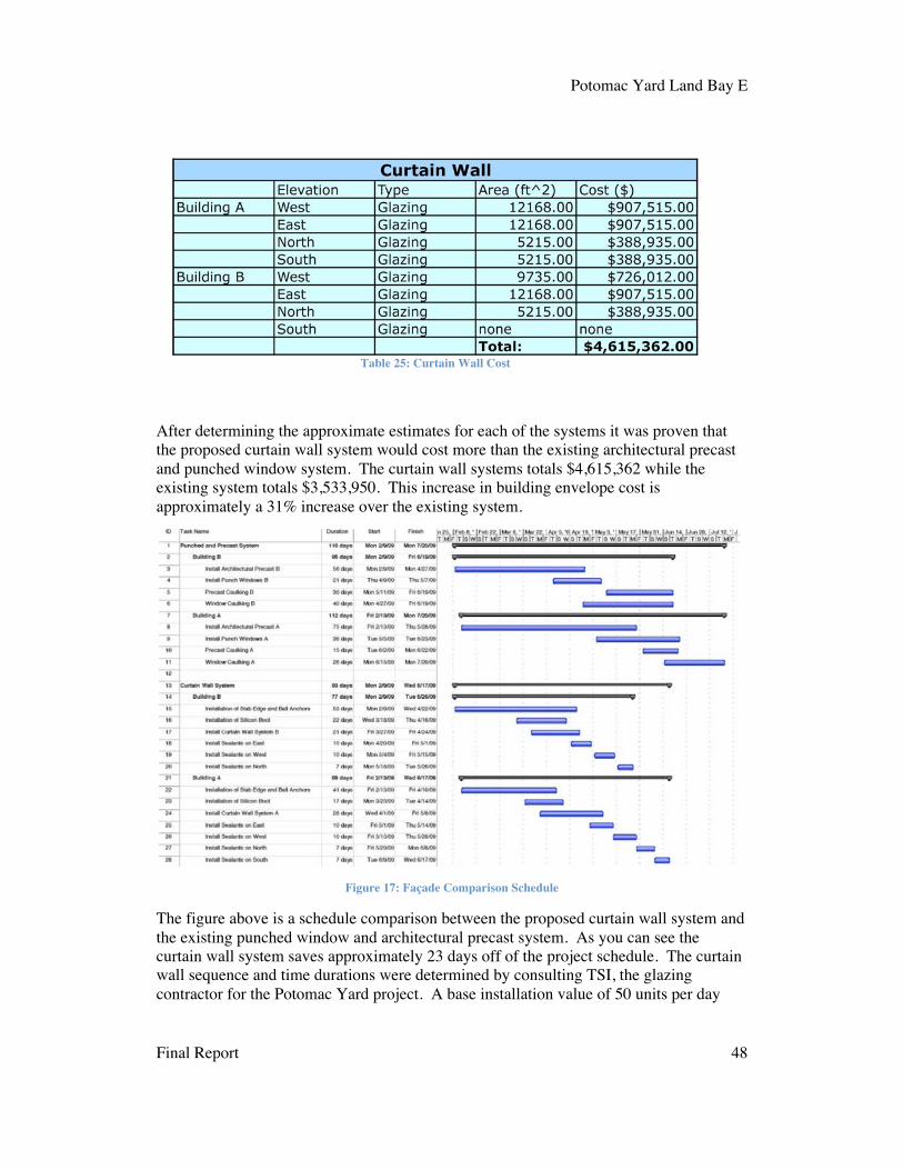
Potomac Yard Land Bay E
Final Report 48
After determining the approximate estimates for each of the systems it was proven that the proposed curtain wall system would cost more than the existing architectural precast and punched window system. The curtain wall systems totals $4,615,362 while the existing system totals $3,533,950. This increase in building envelope cost is approximately a 31% increase over the existing system.
Figure 17: Façade Comparison Schedule
The figure above is a schedule comparison between the proposed curtain wall system and the existing punched window and architectural precast system. As you can see the curtain wall system saves approximately 23 days off of the project schedule. The curtain wall sequence and time durations were determined by consulting TSI, the glazing contractor for the Potomac Yard project. A base installation value of 50 units per day
Table 25: Curtain Wall Cost

Potomac Yard Land Bay E
Final Report 49
was used to give the durations for the installation of all activities. To determine the exact time of installation the construction documents and the individual unit size of 5.25’ wide were consulted. It was determined that each tower will have a crew performing curtain wall tasks simultaneously.
Each activity was calculated from the following information. For one crew it takes approximately three men installing slab edge anchors and ball anchor. These items are used to set the units onto. Two of the men are actually installing the pieces of material while the third man is shooting elevation to make sure that the installation is correct.This duration is approximately 5days for 50 units. Following the anchors is one worker installing a silicon boot on top of the ball and anchor bedding. This activity takes approximately 2 days per 50 units. After the preparation work is completed the installation of the curtain wall panels may begin. One installation crew involves 8 total workers. Typically two men are operating the floor crane two floors above the floor the curtain wall units are being installed. Three men are used to distribute the curtain wall units from the truck onto the corresponding floor location to be ready for installation.Finally, three men are used to set the units into place and secure them to the connection points.
The general conditions estimate may also be reduced do to the shortening of the schedule as a result of implementing a unitized curtain wall system on this project. The building envelope system was on the critical path for the project’s completion during the construction of the Potomac Yard Land Bay E. By implementing a curtain wall system the project schedule could be reduced by 23 days. As a result of the decreased schedule the general conditions could be reduced from $6,110,382.88 to $6,003,681.58, which is atotal savings of $106,701.30. The percent of contract value could be reduced from 7.98% to 7.84% and the cost per week could be reduced from $71,050.96 to $69,810.25.This is approximately a 1.75% reduction in general conditions cost for the project.
Please see Appendix M for general conditions reduction
10.9 Conclusions and Recommendations:
While conducting research for this analysis it was determined that curtain wall systems have many benefits, which include aesthetically pleasing designs, increased amounts of natural day lighting, units are assembled in controlled factory environments, units contain all necessary parts, doesn’t require external access for installation, speed of installation and numerous outer coatings. Throughout the research on this analysis it has been determined that there are two major disadvantages to this building envelope system. One of the major disadvantages is that the initial cost of the system is more expensive than other types of building envelope systems. The second major disadvantage to a curtain wall system is that acquires a large increase in building heat gain through fenestration.
Before the owner could make a decision whether or not to use this type of building envelope system on their building they would have to consider the following:
• Reduction in project time equals a 1.75% reduction in general conditions • Increased cooling load on the building by 102%

Potomac Yard Land Bay E
Final Report 50
• Increased initial cost of system by 31%
After performing this analysis and taking these three major factors into consideration I would not choose to implement a unitized curtain wall system on the Potomac Yard Land Bay E project. I do not believe that the reduction in the project schedule and general conditions is enough to outweigh the dramatic increase in the building’s cooling load and the increase in initial cost. Simply, the architectural precast and punched window system is a better bang for your buck system when looking at the bottom line figures.

Potomac Yard Land Bay E
Final Report 51
11 Chilled Beam Implementation
11.1 Opportunity Statement:
During the 2009 PACE Roundtable event there were many topics discussed. One of the most important topics discussed during this event was the energy consumption of commercial buildings in the United States. During this breakout session many new technologies were identified to be possible ways to reduce the amount of energy consumed by commercial buildings. Many of the items discussed where automated building systems, LED lighting, new types of insulation, reuse of materials and hydronic heating and cooling systems. Over the past ten years Europe and Australia have been using a new technology called a chilled beam mechanical system to heat and cool certain spaces. Most recently the United States has began to use this energy efficient system.
The current mechanical system used on the Potomac Yard Land Bay E project is a typical forced air VAV distribution system. The disadvantage with this system is that it uses large ductwork to distribute its forced air throughout the building’s floor areas. The Potomac Yard Land Bay E project is also projected to achieve a LEED Gold rating upon completion. A way to further reduce energy consumption on this project would be to replace the current mechanical system with a more efficient system. To help reduce the energy consumption of this building the implementation of a chilled beam mechanical system could be used. The advantages for using this type of mechanical system is that the floor-to-floor height will be reduced thus reducing the area of conditioned space and the amount of concrete used in the structure. Another advantage of using this type of mechanical distribution system is that it consumes less energy than a forced air system, which would help with the building’s total energy consumption.
11.2 Goal:
The purpose of this study is to determine the different types of chilled beam systems available on the market today and discover the advantages and disadvantages to using this system over a conventional VAV metal duct system. Also when implementing chilled beams on this project it will be determined if the decreased floor to floor height will help decrease the amount of conditioned air in the building and structural concrete.Finally, it will be determined if the installation process of the supply lines, supply air and beams for this new system would be more efficient than the existing system.
11.3 Methodology:
• Research the advantages and disadvantages of a chilled beam system• Research different types of chilled beams• Determine best product for use• Contact Trox for product data• Determine height savings• Determine reduction in conditioned space• Compare durations of installation for forced air and hydronic systems• Compare costs of two systems

Potomac Yard Land Bay E
Final Report 52
• Draw conclusions and make recommendations concerning application
11.4 Tools and Resources:
• Construction documents • Trox sales representative• DAVIS Constitution Center project team• Internet articles and online sources
11.5 Expected Outcome:
When comparing the initial cost of the two systems I expect that the chilled beam mechanical system will cost more than the traditional VAV system. When looking further into my study I believe that it will take more time to run hydronic piping in comparison to the larger forced air metal ductwork that will probably increase the schedule for the mechanical installation. Due to the reduction in floor-to-floor height the amount of conditioned space should be reduced lowering the demand on the mechanical equipment to condition the air in the building. Also by reducing the floor-to-floor height the building height will be reduced which will reduce the amount of concrete used to construct the building’s columns.
11.6 Research:
Traditionally in years past, commercial buildings in the United States have delivered cool air to its interior spaces to condition the occupied space. In recent years an emerging technology that has been used in foreign countries like Australia and European nations has been gaining popularity in the United States. Chilled beam mechanical systems are very efficient tools to control a building’s indoor temperature for the building’s occupants. This system utilizes chilled water to cool the building’s interior spaces by transporting the energy through small water pipes to ceiling units. The reason that this method of cooling is so efficient is because the distribution of energy is much better through water than through forced air. It has been determined that a 1” diameter water distribution pipe can transport the same cooling energy throughout the building as an 18” square metal ductwork supply.
The reason that in years past the chilled beam mechanical system was not used in the United States was because it was too expensive for owners to install in their buildings.The reason that this system was so expensive is because all of the manufacturers of these items were made overseas and were very costly to transport over long distances. Another reason that this system was not common in the States is because contractors were not familiar with the installation methods for this system. For those that did try and install them they were not very fast and had to learn along the way, thus costing the owner an additional amount of money. Of lately due to the increased demand for energy conservation these mechanical systems are becoming much more popular and easier to install in the United States. There are three common types of chilled beams that are being used in the United States today, which include passive, active and multifunction chilled beams.

Potomac Yard Land Bay E
Final Report 53
Passive Chilled Beams-
Passive chilled beams are the simplest type of chilled beam on the market with an average cooling capacity of 50Btuh/sf. The reason for this is because it requires less material to supply the beam and it has no moving parts within the unit. The maintenance on this unit is minimal due to the simplicity of its design. The way this system works is it is supplied with chilled water through small piping that flows into the unit and reaches a series of coils, typically made of either aluminum or copper. Once the fluid passes through the cooling coils in the unit it then moves into the return piping to be chilled again at a central location. The passive chilled beam relies on the natural convection process. Convection is the process by which energy is transferred through a common medium like a gas or a fluid.
In order for natural convection to work the chilled beam unit must be mounted close to the ceiling leaving enough space for the warmer buoyant air to reach the underside of the mounting surface and then drop into the top of the chilled beam. Once the air enters the unit it is cooled by the series of fins and tubes that make up the inside of the unit. After the air is cooled it exits the beam on the underside and falls to the floor level to cool the occupants and the equipment. Once the air is then reheated by the occupants and equipment the air rises and starts the process all over again.
Figure 18: Passive Chilled Beam
As stated before there are no moving parts in a passive chilled beam, it runs solely on the natural process of convection, which prevents need for fans or any other circulating equipment. For these reasons the operation of this unit is virtually silent and comfortable to be around. This system actually is more comfortable because there is not any forced air creating a draft in the occupied space. Passive chilled beams do not use any ventilation to the conditioned space so additional ventilation must be required to serve the occupied space. Although this would require some ductwork it is much smaller and not as extensive as an all air system.

Potomac Yard Land Bay E
Final Report 54
The installation of a passive chilled beam may be either hung by itself like a pendant light fixture, stand alone or mounted flush with an acoustical ceiling. When installing the beams it is critical to place them in the appropriate locations. Optimum locations for placement are parallel and adjacent to exterior perimeter walls because the solar gain from the windows will help with the natural convection process. The heat generated from the windows will rise faster and increase the flow of air through the unit. Locations that are not best suited for beam placement are above workstations, copiers and kitchen appliances. A chilled beam should not be placed above a workstation because the draft from the unit may be disruptive to the worker. Placement of a unit above a copier or other heat generators will counteract the flow of air from the unit from reaching the building occupants.
Figure 19: Trox Passive Beam w/ Fluid Lines
Passive chilled beams may be used in all types of climates with some considerations in mind. This system may even be used in hot and humid environments if the building is sealed from the outside air and the humidity is controlled. Along with controlling the humidity in the building it is important that the supply of chilled water to the unit is kept approximately 2 degrees above the room’s dew point in order to prevent condensation off the pipes and mold growth around the insulation. Typically the chilled water used to supply the passive system is warmer than typical chilled water so the size of the building’s chillers may be reduced. In some circumstances ground water may be used to supply chilled water to the units thus reducing the building’s energy consumption even further.
Active Chilled Beams-
Active chilled beams are more complex units than an active chilled beam mechanical system and have an average cooling capacity of 80 Btuh/sf. Active chilled beams use much of the same concepts as the passive ones but with one major difference, the active beams integrate the use of ventilation air supply. This system still relies on the assistance of natural convection throughout the floor space to circulate the air but also incorporate the dehumidified supply air from a central location in the building. This eliminates the need for another fresh air system like the one required for the passive system. Another

Potomac Yard Land Bay E
Final Report 55
great feature of the active chilled beam system is that is may be used for either heating or cooling. This is accomplished by the temperature of the water being supplied to the coils within the unit and the velocity of the ventilated air leaving the unit.
Figure 20: Active Chilled Beam
Active chilled beams can be installed up against the mounting structure as seen from the figure above. This system operates with the help of natural convection within the space it is conditioning. Warm air rises from the floor up to the beam and is drawn into the bottom of the unit by the temperature differential that is supplied by the heat exchanger inside. Once the air is inside the unit it is cooled by the heat exchanger coils and then mixed with the ventilated air supply. The ventilated supply air is introduced into the chamber at a high velocity to thoroughly mix with the cooled air. After mixing the air it is discharged into the room through a diffuser located on the bottom of the unit. Again like the passive system the cool air proceeds to fall to the floor to cool the occupants and equipment. After the air is heated it then rises towards the induction chamber of the unit and then the process is repeated.
Like passive chilled beams, active systems require very little maintenance because there are very few moving parts in comparison to a conventional VAV mechanical system.Even though the active system incorporates a supply of ventilated air to the process it still requires a much smaller volume of air in comparison to an all air system. Active systems are able to produce a high cooling potential than the passive systems because of the high velocity of the ventilated air being mixed within the beam. This allows the discharge temperature of the air leaving the unit to be higher than a traditional all air system allowing for a more comfortable room atmosphere. Because the active system utilizes a small volume of high velocity air the total volume of forced air used is approximately 50-75% lower than a conventional air conditioning system.
Installations of active systems are typically flush mounted units that are incorporated with an acoustical ceiling tile system. When installing an active system in a building the ceiling height is used to determine the spacing of the units to achieve optimum performance from the system. Active chilled beams may be installed to act independently or in a zone. Unlike the passive chilled beam placement of the units above

Potomac Yard Land Bay E
Final Report 56
a heat generator or workstation is not a concern. The reason for this is that the warm air is inducted into the unit through the bottom center of the beam and the conditioned air is dispersed through a diffuser at angles greater than 30 degrees from vertical directly below the unit.
Active systems also have another advantage over the passive systems, which is the ability to supply heat and cooling to a space. This is accomplished because of the integration of the ventilated air supply into the beams. When the heating mode is desired the supply water into the unit must be at a higher temperature in order to warm the heat exchanger to transfer the heat into the inducted air. Once the air is heated it is then mixed and forced out of the unit towards the occupied space by the high velocity supply air. An active chilled beam that has the function for both heating and cooling will typically have four pipes connected to the unit. Two of the pipes will be the supply, one for hot water and one for chilled water. The other two pipes are the returns for both the hot and chilled water. Along with the piping of water being connected to the unit there will be a connection for the forced air supply in the top of the unit. The temperature of the water being supplied to the beams depends on the thermostat that controls a particular zone.Different zones in a building may perform separate tasks like in one zone the thermostat may call for heat and the beams will produce heat while in another zone the thermostat may call for cooling and the beams will cool the space.
Multiservice Chilled Beam-
Multiservice chilled beams may be either active or passive systems. This type of chilled beam incorporates other building systems with it in one prefabricated unit. Typically larger than the other two systems, it may contain a variety of building systems, which include:
• Lighting• Sprinklers• Public Address System • Motion detector and other BA Systems
Figure 22: Active Beam Heating Mode Figure 21: Active Beam Cooling Mode

Potomac Yard Land Bay E
Final Report 57
• Wire ways
These units are obviously much larger than the single function systems and much more expensive. However, these units are very compact in comparison to all of the individual systems it houses. By having the variety of components within the unit, construction may be shortened dramatically. The need for drop ceilings is an option because all of the components for the building to operate are in a compact area. This may reduce the cost of hangers and installation materials.
Advantages-
Chilled beams have many advantages over conventional all air mechanical systems.Chilled beam systems use approximately 50-75% less air ventilated air than forced air systems. This is achieved by using water as a transportation medium for cooling a space.Water is much more dense than air, which allows it to be more efficient for transferring energy throughout a building. In many case studies it has been determined that by using a chilled beam mechanical system over a conventional VAV system a building will consume much less energy. An example of this is the Constitution Center in Washington DC. This is a 1.4 million square feet office building-remodeling job that is being fitted out with all new construction materials and is projected to achieve a LEED Silver Certification. This building is utilizing active chilled beams on all of the typical floors.The mechanical designers of the building project that the building will consume approximately 23% less energy than a typical all air mechanical system compliant with ASHRAE 90.1 standard.
The comfort of the conditioned space for the building occupants is much better than a conventional all air system. The lower discharge air velocity coming from the units improves comfort in the occupied area. The conditioned air is mixed much better inside of the unit before it is discharged into the room unlike all air systems that mix the air after entering the room. Chilled beams also reduce the size of metal ductwork for forced air in the building. This is accomplished because the need for ventilated air is dramatically reduced, thus reducing overall ductwork, air handlers and fan energy. By reducing the size of the ductwork used on a building two things may happen, the floor-to-floor height
Figure 23: Trox Multi-Service Chilled Beam

Potomac Yard Land Bay E
Final Report 58
may be reduced or the floor to ceiling height may be increased. By increasing the ceiling height architects may add larger lights and other amenities to the building that may increase occupant comfort. By lowering the floor-to-floor height many things may be achieved:
• Less structural material consumed • Decreased volume of conditioned space • Higher percentage of outside air, creating healthier indoor environment • Allow for more floors to be added where height restrictions are enforced
Chilled beams also require less maintenance than conventional all air systems, which reduces the life-cycle cost of the system. This system only requires periodic vacuuming of the coils within the unit approximately every five years to ensure optimum performance. Because of the chilled beam’s lack of moving parts there are virtually no parts of the system that will fail if installed properly. Chilled beams have virtually no noise of operation due to the lack of moving parts. Passive chilled beams are virtually silent while active beams produce a small amount of noise, less than 30 dB, from the high velocity ventilated air.
Other advantages to implementing a chilled beam mechanical system is that there are no electrical connections involved with the beams. This can dramatically reduce electrical installation and wire costs during construction. Controls for a chilled beam system are far less complex than the ones used on all air systems containing VAV boxes.Commissioning for a chilled beam system are much less complicated and time consuming when compared to a typical mechanical system. Only small adjustments through the water balancing valves and primary air balancing dampers through easy pressure readings are needed to complete the system’s commissioning.
Disadvantages-
The major disadvantage of a chilled beam mechanical system is the high initial cost of material and installation. There are many reasons for the increased initial cost of this system. One major factor to the increased price is the unfamiliarity of contractor’s installation methods. Another reason for the high cost of the material is that most of the products come from overseas. Although metal ductwork decreases when implementing this system other items are needed. Some of the increased cost for this system is attributed to the cost of the unit, the need for piping, insulation for water pipes and pumps to circulate the water.
There are many applications that chilled beams are not suited for like spaces with high ceilings and rooms with high humidity. Humidity must be monitored closely to ensure that mold and condensation does not form. Buildings that use this mechanical system must be sealed and dehumidified; operable windows and other means of allowing unconditioned outside air into the occupied space are unacceptable. Locations that are not well suited for the use of chilled beams are lobbies, exercise rooms, indoor pools and kitchens.
11.7 Conditioned Air Volume and CIP Savings:
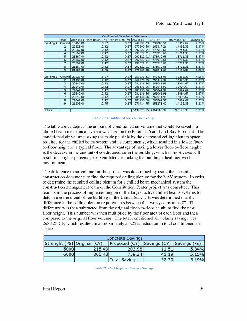
Potomac Yard Land Bay E
Final Report 59
Table 26: Conditioned Air Volume Savings
The table above depicts the amount of conditioned air volume that would be saved if a chilled beam mechanical system was used on the Potomac Yard Land Bay E project. The conditioned air volume savings is made possible by the decreased ceiling plenum space required for the chilled beam system and its components, which resulted in a lower floor-to-floor height on a typical floor. The advantage of having a lower floor-to-floor height is the decease in the amount of conditioned air in the building, which in most cases will result in a higher percentage of ventilated air making the building a healthier work environment.
The difference in air volume for this project was determined by using the current construction documents to find the required ceiling plenum for the VAV system. In order to determine the required ceiling plenum for a chilled beam mechanical system the construction management team on the Constitution Center project was consulted. This team is in the process of implementing on of the largest active chilled beams systems to date in a commercial office building in the United States. It was determined that the difference in the ceiling plenum requirements between the two systems to be 8”. This difference was then subtracted from the original floor-to-floor height to find the new floor height. This number was then multiplied by the floor area of each floor and then compared to the original floor volume. The total conditioned air volume savings was 268,123 CF, which resulted in approximately a 5.22% reduction in total conditioned air space.
Table 27: Cast-in-place Concrete Savings

Potomac Yard Land Bay E
Final Report 60
The table above summarizes the amount of cast-in-place structural concrete saved when implementing a chilled beam mechanical system compared to a typical all air system.The CIP concrete savings is a result of the lower floor-to-floor heights required to support the proposed system. All of the concrete savings occur within the column construction of the building. The total amount of concrete savings is approximately 52.7CY of concrete, which is about 5.19% of the total concrete used for all of the columns in the building.Assuming that each concrete truck holds approximately 9CY of concrete, there will be a savings of six truck loads of concrete brought to the site thus freeing up a portion of the site for other deliveries.
Please see Appendix N for Concrete Savings
The table above summarizes the cost savings of CIP concrete for the columns in the building. RS Means provided the pricing information for the CIP concrete. This price includes material, placement and delivery. The total cost savings for CIP concrete from the implementation of a chilled beam mechanical system is $72,462.50. When this value is adjusted for location, Arlington Virginia, the total savings amounts to $67,390.13.
11.8 Cost and Schedule Impacts:
The cost and schedule considerations compared in this analysis involve the comparison between the VAV and chilled beam units and supply air ducts and water piping material for both systems. In order to determine the cost differential between the two systems the following information was used:
Chilled Beam System- information provided by DAVIS mechanical team at Constitution Center
• Union labor rate $54 • 1” pipe $600/100’ including fittings • 1 hour for beam installation • 30hours/100’ of pipe • 25”x5” trunk duct • $1800/100’ duct • 25 hours to fabricate and install duct • $30 flex duct supplying individual unit • Chilled beam cost $800 • 18 beams for 2700s.f.
Building A Typical Floor:
Table 28: Cast-in-place Concrete Cost Savings

Potomac Yard Land Bay E
Final Report 61
Ductwork-
• Material: $9,216 • Installation: $6,912
1” piping-
• Material: $12,288 • Installation: $33,178
Chilled Beams-
• Material: $125,600 • Installation: $8,478
Total Per Floor = $195,672
Total Building A, Floors 2-9 = $1,565,376
Building B Typical Floor:
Ductwork-
• Material: $8,280 • Installation: $6,480
1” piping-
• Material: $11,520 • Installation: $31,104
Chilled Beams-
• Material: $120,000 • Installation: $8,100
Total Per Floor = $185,484
Total Building B, Floors 2-9 = $1,483,872
Total Building Cost = $3,049,248
This number only includes typical office space floors, which are floors 2-9. The ground floor and P-levels are not suitable for chilled beam implementation because of function and ceiling height. Again this is an estimate only involving the unit itself and the material needed to supply the units, not the whole mechanical system.

Potomac Yard Land Bay E
Final Report 62
VAV System- information provided by DAVIS mechanical team at Constitution Center
• Union labor $54 • Assuming average duct size 2’x3’ • Material $240/12’ • 3 hours fabrication for 12’ • 10 hours installation for 12’ • VAV $2500 including local controls • 4 hours for VAV installation
Building A Typical Floor:
Ductwork-
• Material: $9,520 • Installation: $27,846
VAV w/ controls-
• Material: $90,000 • Installation: $7,776
Total Per Floor = $135,142
Total Building A, Floors 2-9 = $1,081,136
Building B Typical Floor:
Ductwork-
• Material: $9,200 • Installation: $26,910
VAV w/ controls-
• Material: $85,000 • Installation: $7,344
Total Per Floor = $128,454
Total Building B, Floors 2-9 = $1,027,632
Total Building Cost = $2,108,768
When comparing the two systems the chilled beam system is 45% higher than the VAV system. This is higher than the more common 20-30% increase in cost between the two systems. The reason that this is so high is because is because the cost savings for air handlers, fans and controls were not taken into consideration during this analysis. Given more time and the appropriate resources to determine the total system cost differences it would have been found that the chilled beam system would have been in the range of 20-30% more than the all air system. However, the initial cost is one important

Potomac Yard Land Bay E
Final Report 63
consideration when looking at implementing a new system but the payback period is just as important. Typically, a chilled beam mechanical system should pay for itself in energy savings in approximately 7-10 years, said a member of the Constitution Center mechanical team. After the system has paid for itself it will continue to save money throughout its lifecycle, which could amount to significant dollars especially with energy inflation near 5% a year.
When taking into consideration the schedule impacts of implementing a chilled beam mechanical system to the Potomac Yard Land Bay E project, the duration of installing this system is not critical to the project’s completion. However, it is still important to take into account how long it will take to install the components of this system. When comparing the installation of just the ductwork and VAV units to the ductwork, piping and chilled beams the proposed system takes approximately 54% longer to install. The traditional all air system would take approximately 102 days to complete while the chilled beam system would take approximately 157 days to complete. The information used to determine the original systems duration was the schedule for the project. The Constitution Center mechanical team provided the information used to determine the duration for the chilled beam system. The assumptions used where the following:
• 5 men crew • Ductwork: 19hr/100’ • Piping: 30hr/100’ • Beams: 1hr/beam
Please see Appendix O for Schedule Comparison between chilled beam system and all air system.
11.9 Conclusions and Recommendations:
After conducting research for this analysis it has been determined that chilled beam technology is a more efficient mechanical system than an all air mechanical system.Chilled beams utilize water as the means of transporting the cooling energy throughout the building. Water is much more dense than traditionally used air, this means that water may transfer much more energy in a smaller volume. As stated before a 1” water pipe contains the same cooling capacity as an 18’ air duct. This eliminates the need for large amounts of metal ductwork servicing buildings, which allows for a reduced ceiling plenum. As previously stated there are many benefits to installing a chilled beam mechanical system, which include:
• Increased energy savings • Higher floor-to-ceiling height • Lower floor-to-floor height
o Concrete savings o Conditioned air volume savings o Higher percentage of outside air o Allows for more floors in height restricted regions
• Increased occupant comfort, better air dispersion

Potomac Yard Land Bay E
Final Report 64
Before the owner could make a decision whether or not to implement a chilled beam mechanical system on their project instead of the existing system they would have to consider the cost and schedule implications. If the owner where to switch to a chilled beam system they would decrease the total amount of conditioned air volume with in the building by 5.22%. This would increase the percentage of ventilated air into the occupied floors and reduce the load on the mechanical system. The owner would also benefit from a 5.19% savings in structural concrete in the columns. This translates to 52.7CY of concrete and a cost savings of $67,390.13. When comparing the initial cost of the two systems the chilled beam system will cost approximately 45% higher than the all air system. If a study of the reduction in AHUs, fans and controls where performed the percentage difference would become smaller. There is not a need to be concerned about the schedule because the mechanical rough in is not on the critical path of this project.However, to install this system it would take approximately 54% longer duration to complete when compared to the VAV system.
After reviewing the findings of this analysis I would recommend this system to the ownership of the Potomac Yard Land Bay E project. By installing this system they will receive many benefits that will be noticed immediately and some that will ongoing throughout the life of the building. As time progresses and this technology becomes more popular within the United States contractors will become more familiar with installation methods and the prices of the units will fall as more competition enters the market hoping to capitalize on a piece of the action.

Potomac Yard Land Bay E
Final Report 65
12 Conclusions: After conducting all three analyses many advantages and disadvantages have been discovered. From an owner’s perspective they are looking for fast, efficient, cost effective and quality construction for their project. These analyses look at saving the owner money by making the building more efficient and shortening the construction process by using prefabricated materials. The first analysis looks at the addition of a supplemental energy source on the rooftop of the existing white TPO roof. The last two analyses look at comparing existing building systems to other commonly used systems on new construction today.
The first analysis looks at the implementation of a Solyndra PV system on the roof of both buildings. The study shows that the proposed system will provide a savings of $38,650 during the first year after installation. When using a 5% cost of energy increase per year it was determined that the system will pay for itself with in 22 years of operation. This is within the 25-year warranty period, in fact, by the end of the warranty the owner will save $402,622.63 in energy costs.
The second analysis involves implementing a unitized curtain wall system in place of the existing architectural precast and punched window façade. This was proposed to shorten the schedule and provide more natural daylight to the interior space. This study showed that the total project schedule would be shortened by 23 days and reduces the general conditions by 1.75%. This translates into a savings of $106,701.30 for the project.However, it was determined that the curtain wall system would cost 31% higher than the existing system and would more than double the cooling load on the building by solar heat gain through the increased glazing.
The third analysis incorporated replacing the current all air mechanical system with a more energy efficient chilled beam mechanical system. This analysis only involved the comparison between the distribution equipment and supply material. From this analysis it was determined that by implementing this system the owner would save 52.7 CY of concrete, which translates to a $67,390.13 cost savings on CIP concrete for the columns.The owner would also save 5.22% of conditioned air volume in the building to allow for a higher percentage of ventilated air in the building. However, when comparing the duration of installation and initial cost the new system cost approximately 45% more to install and take 54% longer time to complete.
After looking over the findings for each of the three analyses it was determined that the first and third analyses would be good decisions for the owner to implement. By implementing these two systems to the building the owner would achieve a more sustainable image to the public and LEED officials. Assuming that the owner keeps the building and does not perform any major renovations for forty years they will be saving tremendous amounts of money through energy savings. Energy prices are only going to skyrocket due to the current energy crisis. Assuming that energy costs rise at a constant rate of 5% in the DC metro area the cost of energy may reach $.92 per kWh. At the future price of $.92/kWh the energy savings for the Solydra panels alone would reach $3,226,836.

Potomac Yard Land Bay E
Final Report 66
13 Work Cited:
1997 ASHRAE Handbook I-P Edition. 1997 Copyright by the American Society of
Heating, Refrigerating and Air-Conditioning Engineers, Inc.
Bureau of Labor Statistics. Mid-Atlantic Information. February 2010
http://www.bls.gov/ro3/apwb.htm
Continuing Education Center. An Energy-Conserving Technology From Europe Makes
Inroads in the U.S. February 2010
http://continuingeducation.construction.com/article.php?L=5&C=463
Dadanco. Benefits. February 2010
http://activechilledbeam.com/cheap_low_energy_cooling.asp?section=cost
Enclos Corp. Our Expertise. February 2010 http://enclos.com/
Schultz Carl C. Next-Generation Cooling Is Looking Up. February 2010
http://www.esmagazine.com/Articles/Feature_Article/BNP_GUID_9-5-
2006_A_10000000000000099257
Solyndra. The New Shape of Solar. February 2010 http://www.solyndra.com/
Trox USA. Chilled Beam Products. February 2010
http://www.troxusa.com/usa/index.html
Viracon. Product Data Tables. February 2010 http://www.viracon.com/
Weatherbase. Arlington Virginia. February 2010
http://www.weatherbase.com/weather/weather.php3?s=6844&refer=
Wikipedia. Insolation. February 2010 http://en.wikipedia.org/wiki/Insolation

Potomac Yard Land Bay E
Final Report 67
14 Appendix A:

Pot
omac
Yar
d La
nd B
ay E
D
rew
Hei
lman
10
/05/
09
Exi
stin
gC
ondi
tions
Pro
pert
y Li
ne &
Con
stru
ctio
n F
ence
Bui
ldin
g P
erim
eter
w/ P
arki
ng
Traf
fic F
low
One
Way
Jo
b Tr
aile
rs
Bui
ldin
g H
t: 13
8.32
’ / 9
Sto
ries Ped
estr
ian
Traf
fic
N
Exi
st. S
anita
ry
Exi
st.
Com
mun
icat
ion
Exi
st. G
as
San
itary
Ele
ctric
W
ater
Gas
Pro
p. L
ight
Pol
e F
ire H
ydra
nt
Tem
p. E
lect
ric
Ent
ranc
e
Par
king

Potomac Yard Land Bay E
Final Report 68
14 Appendix B:

By:
Dre
w H
eilm
an
Tec
h 2
Dat
e: O
ctob
er 2
8, 2
009
Str
uctu
ral S
eque
nce:
Gar
age
Lev
els

Potomac Yard Land Bay E
Final Report 69
14 Appendix C:

By:
Dre
w H
eilm
an
Tec
h 2
Dat
e: O
ctob
er 2
8, 2
009
Str
uctu
ral S
eque
nce:
B
uild
ings
A&
B

Potomac Yard Land Bay E
Final Report 70
14 Appendix D:

IDT
ask
Nam
eD
urat
ion
Sta
rtF
inis
h
1P
ropo
sal t
o O
wne
r0
days
Fri
7/13
/07
Fri
7/13
/07
2N
otic
e to
Pro
ceed
0 da
ysT
ue 8
/14/
07T
ue 8
/14/
07
3P
reco
nstr
uctio
n15
8 da
ysT
ue 8
/14/
07T
hu 3
/20/
08
4O
wne
r R
ecei
ving
Per
mits
76 d
ays
Thu
9/1
3/07
Thu
12/
27/0
7
5S
ite D
evel
opm
ent
71 d
ays
Wed
1/2
/08
Wed
4/9
/08
6S
heet
ing/
Sho
ring
104
days
Wed
3/1
2/08
Mon
8/4
/08
7F
ound
atio
n P
iles/
Pile
Cap
s88
day
sF
ri 5/
30/0
8T
ue 9
/30/
08
8S
ite U
tiliti
es16
5 da
ysF
ri 8/
8/08
Thu
3/2
6/09
9G
roun
d F
loor
Con
cret
e82
day
sT
ue 9
/23/
08W
ed 1
/14/
09
10A
bove
Gra
de C
oncr
ete
Str
uctu
re B
74 d
ays
Mon
12/
8/08
Thu
3/1
9/09
11A
bove
Gra
de C
oncr
ete
Str
uctu
re A
60 d
ays
Mon
12/
22/0
8F
ri 3/
13/0
9
12T
op O
ut B
uild
ing
B0
days
Thu
3/1
9/09
Thu
3/1
9/09
13A
rch
Pre
cast
Bld
g B
56 d
ays
Mon
2/9
/09
Mon
4/2
7/09
14B
uild
ing
B C
ore
Fin
ishe
s13
7 da
ysF
ri 2/
13/0
9M
on 8
/24/
09
15M
ain
Lobb
y In
terio
r B
ldg
B12
6 da
ysT
hu 2
/12/
09T
hu 8
/6/0
9
16B
uild
ing
A C
ore
Fin
ishe
s11
6 da
ysT
ue 3
/3/0
9T
ue 8
/11/
09
17M
EP
and
Spr
ikle
r B
ldg
B90
day
sT
ue 3
/31/
09M
on 8
/3/0
9
18E
leva
tors
Bld
g B
119
days
Tue
3/3
1/09
Fri
9/11
/09
19E
leva
tors
Bld
g A
101
days
Mon
4/6
/09
Mon
8/2
4/09
20M
EP
and
Spr
inkl
er B
ldg
A69
day
sT
ue 4
/28/
09F
ri 7/
31/0
9
21T
op O
ut B
uild
ing
A0
days
Wed
4/2
9/09
Wed
4/2
9/09
22A
rch
Pre
cast
Bld
g A
72 d
ays
Tue
5/5
/09
Wed
8/1
2/09
23M
EP
Gar
age
Leve
ls24
day
sF
ri 6/
5/09
Wed
7/8
/09
24S
ite W
ork/
Lan
dsca
ping
57 d
ays
Mon
6/2
9/09
Tue
9/1
5/09
25In
spec
tions
15 d
ays
Mon
8/2
4/09
Fri
9/11
/09
26B
uild
ing
A&
B W
ater
tight
0 da
ysF
ri 9/
4/09
Fri
9/4/
09
27S
ubst
aint
ial C
ompl
etio
n0
days
Wed
9/3
0/09
Wed
9/3
0/09
28P
unch
list
10 d
ays
Wed
9/3
0/09
Tue
10/
13/0
9
29P
roje
ct C
ompl
etio
n0
days
Thu
10/
1/09
Thu
10/
1/09
7/13
8/14
FT
SW
ST
M 1
7, '0
7S
ep 9
, '07
Dec
2, '
07F
eb 2
4, '0
8
Tas
k
Spl
it
Pro
gres
s
Mile
ston
e
Sum
mar
y
Pro
ject
Sum
mar
y
Ext
erna
l Tas
ks
Ext
erna
l Mile
ston
e
Dea
dlin
e
Pro
ject
Sum
mar
y S
ched
ule
Pag
e 1
Dre
w H
eilm
anA
E S
enio
r T
hesi
s

3/19
4/29
9/4
FT
SW
ST
MF
TS
WS
TM
May
18,
'08
Aug
10,
'08
Nov
2, '
08Ja
n 25
, '09
Apr
19,
'09
Jul 1
2, '0
9
Tas
k
Spl
it
Pro
gres
s
Mile
ston
e
Sum
mar
y
Pro
ject
Sum
mar
y
Ext
erna
l Tas
ks
Ext
erna
l Mile
ston
e
Dea
dlin
e
Pro
ject
Sum
mar
y S
ched
ule
Pag
e 2
Dre
w H
eilm
anA
E S
enio
r T
hesi
s

Potomac Yard Land Bay E
Final Report 71
14 Appendix E:

Statement of Probable CostTuesday, September 29, 2009 Page 1
Land Bay E - Oct 2008 - VA - Arlington
Prepared By: Drew Heilman Prepared For: Penn State AE DepartmentAE Senior Thesis 2010The Pennsylvania State University 104 EUAUniversity Park, Pa 16802 University Park, Pa 16802717.873.1210 Fax: Fax:
Building Sq. Size: 369300 Site Sq. Size: 216643Bid Date: Building use: Office
No. of floors: 9 Foundation: PILNo. of buildings: 2 Exterior Walls: PRE
Project Height: 138.32 Interior Walls:1st Floor Height: Roof Type: MEM
1st Floor Size: Floor Type: CONProject Type: NEW
Division Percent Sq. Cost Amount 00 Bidding Requirements 3.15 3.87 1,430,841
Bidding Requirements 3.15 3.87 1,430,841
01 General Requirements 12.05 14.83 5,476,682General Requirements 12.05 14.83 5,476,682
02 Site Work 5.76 7.09 2,619,383Site Work 5.76 7.09 2,619,383
03 Concrete 23.48 28.90 10,672,842Concrete 23.48 28.90 10,672,842
04 Masonry 1.54 1.89 699,400Masonry 1.54 1.89 699,400
05 Metals 7.60 9.35 3,452,036Metals 7.60 9.35 3,452,036
06 Wood & Plastics 0.31 0.39 142,375Wood & Plastics 0.31 0.39 142,375
07 Thermal & Moisture Protection 1.36 1.67 617,607Thermal & Moisture Protection 1.36 1.67 617,607
08 Doors & Windows 15.30 18.82 6,951,740Doors & Windows 15.30 18.82 6,951,740
09 Finishes 3.59 4.42 1,632,282Finishes 3.59 4.42 1,632,282
10 Specialties 1.89 2.33 860,576Specialties 1.89 2.33 860,576
11 Equipment 0.08 0.10 35,856Equipment 0.08 0.10 35,856
12 Furnishings 1.06 1.31 482,962Furnishings 1.06 1.31 482,962
14 Conveying Systems 4.13 5.08 1,875,990Conveying Systems 4.13 5.08 1,875,990
15 Mechanical 12.02 14.79 5,461,850Mechanical 12.02 14.79 5,461,850
16 Electrical 6.68 8.22 3,036,306Electrical 6.68 8.22 3,036,306
Total Building Costs 100.00 123.07 45,448,726
Total Non-Building Costs 100.00 0.00 0

Tuesday, September 29, 2009 Page 2
Total Project Costs -- -- 45,448,726

Statement of Probable CostTuesday, September 29, 2009 Page 1
Land Bay E Parking - Oct 2008 - VA - Arlington
Prepared By: Drew Heilman Prepared For: Penn State AE DepartmentAE Senior Thesis 2010The Pennsylvania State University 104 EUAUniversity Park, Pa 16802 University Park, Pa 16802717.873.1210 Fax: Fax:
Building Sq. Size: 235000 Site Sq. Size: 23677Bid Date: Building use: Commercial
No. of floors: 3 Foundation: PILNo. of buildings: 1 Exterior Walls: CON
Project Height: Interior Walls:1st Floor Height: Roof Type:
1st Floor Size: Floor Type: CONProject Type: NEW
Division Percent Sq. Cost Amount 00 Procurement and Contracting Require 4.74 3.62 850,145
Procurement and Contracting Require 4.74 3.62 850,145
01 General Requirements 3.65 2.78 654,152General Requirements 3.65 2.78 654,152
02 Site Work 10.64 8.12 1,907,629Site Work 10.64 8.12 1,907,629
03 Concrete 52.89 40.36 9,485,701Concrete 52.89 40.36 9,485,701
04 Masonry 0.39 0.29 69,281Masonry 0.39 0.29 69,281
05 Metals 4.47 3.41 802,395Metals 4.47 3.41 802,395
06 Wood & Plastics 0.06 0.04 10,052Wood & Plastics 0.06 0.04 10,052
07 Thermal & Moisture Protection 1.83 1.40 328,018Thermal & Moisture Protection 1.83 1.40 328,018
08 Doors & Windows 6.68 5.10 1,197,760Doors & Windows 6.68 5.10 1,197,760
09 Finishes 0.59 0.45 105,647Finishes 0.59 0.45 105,647
10 Specialties 0.37 0.28 66,427Specialties 0.37 0.28 66,427
11 Equipment 0.73 0.55 130,198Equipment 0.73 0.55 130,198
14 Conveying Systems 1.76 1.35 316,147Conveying Systems 1.76 1.35 316,147
15 Mechanical 3.89 2.97 698,528Mechanical 3.89 2.97 698,528
16 Electrical 4.60 3.51 825,422Electrical 4.60 3.51 825,422
21 Fire Suppression 0.37 0.28 65,725Fire Suppression 0.37 0.28 65,725
22 Plumbing 0.52 0.40 93,706Plumbing 0.52 0.40 93,706
26 Electrical 1.83 1.40 328,625Electrical 1.83 1.40 328,625

Tuesday, September 29, 2009 Page 2
Total Building Costs 100.00 76.32 17,935,558
Total Non-Building Costs 100.00 0.00 0
Total Project Costs -- -- 17,935,558

Potomac Yard Land Bay E
Final Report 72
14 Appendix F:
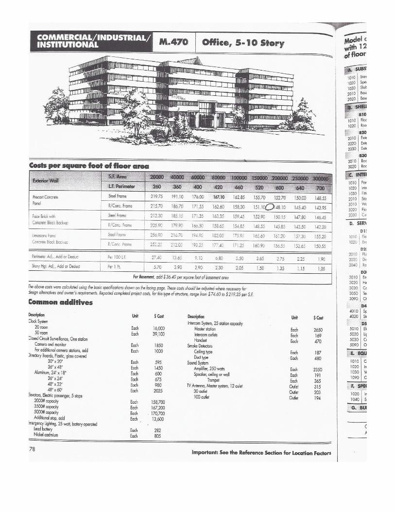


Potomac Yard Land Bay E
Final Report 73
14 Appendix G:

Description Time on Job Quantity Unit Unit Price TotalProject Executive 30% 86 week $1,144.00 $98,384.00
Senior Project Manager 80% 86 week $2,653.00 $182,526.40Project Managers (2) 100% 86 week $2,083.00 $358,276.00
Assistant Project Managers (2) 100% 86 week $1,555.00 $267,460.00Superintendents (2) 100% 86 week $3,345.00 $575,340.00
Assistant Superintendents (1) 100% 86 week $2,465.00 $211,990.00Safety 10% 86 week $161.00 $13,846.00
Layout Engineer 60% 86 week $1,373.00 $118,078.00Total Cost $1,825,900.40
Description Quantity Unit Duration Unit Price TotalHeat 1 CSF/week 20 $12.50 $154,750.00
Lighting 1 CSF $29.42 $18,210.98Power 1 CSF $51.70 $32,002.30Toilets 8 Month 20 $162.00 $25,920.00
Total Cost $230,883.28
Description Quantity Unit Duration Unit Price TotalTrailers 4 EA/month 10 $410.00 $16,400.00
Storage Boxes 3 EA/month 10 $79.00 $2,370.00Field Office Equipment Rental 4 Month 10 $171.00 $6,840.00
Office Supplies 4 Month 10 $93.50 $3,740.00Field Office Lights & HVAC 4 Month 10 $165.00 $6,600.00
Scaffolding 30 CSF $124.00 $3,720.00Fencing 808 LF $11.15 $9,009.20Signage 100 SF $25.00 $2,500.00
Dumpsters 4 Week 86 $620.00 $213,280.00Tower Crane/ Material Hoist (Trades) $0.00
Testing and Inspections (Owner) $0.00Total Cost $264,459.20
Quantity Unit Unit Price Total1 LS $383,000.00 $383,000.00
$0.001 LS $459,600.00 $459,600.001 LS $183,840.00 $183,840.00
$0.001 LS $2,762,700.00 $2,762,700.00
Total Cost $3,789,140.00
$6,110,382.887.98
$305,519.14$71,050.96
% Total Contract ValueCost per MonthCost per Week
DescriptionPermits
Payment and Performance Bond
Builder's Risk Insurance (Owner)Contractors Fee
Building Permit and others (Owner)
General Liability Insurance
General Contrator Staff
Temporary Utilities
Construction Facilities and Equipment
Permits, Insurance and Fee
Total General Conditions

Potomac Yard Land Bay E
Final Report 74
14 Appendix H:


Potomac Yard Land Bay E
Final Report 75
14 Appendix I:

Alb
edo
Ref
lect
ivity
vs.
Ann
ual E
nerg
y Y
ield
•E
nerg
y w
ith W
hite
Mem
bran
e: 8
0% T
op /
20%
Bot
tom
•R
ule
of th
umb:
4%
dro
p in
ref
lect
ivity
= 1
% a
nnua
l ene
rgy
yiel
d lo
ss
Sol
yndr
a C
onfid
entia
l12
Gra
ph is
for
dem
onst
ratio
n pu
rpos
es, n
ot a
ctua
l dat
a

Potomac Yard Land Bay E
Final Report 76
14 Appendix J:

Year Cost Increase/y Energy Cost Energy Produc Cost Savings Savings To-date1 $0.14 282112.24 $38,649.38 $38,649.382 1.05 $0.14 564224.48 $40,581.85 $79,231.223 1.05 $0.15 846336.72 $42,610.94 $121,842.164 1.05 $0.16 1128448.96 $44,741.48 $166,583.655 1.05 $0.17 1410561.20 $46,978.56 $213,562.206 1.05 $0.17 1692673.44 $49,327.49 $262,889.697 1.05 $0.18 1974785.68 $51,793.86 $314,683.558 1.05 $0.19 2256897.92 $54,383.55 $369,067.119 1.05 $0.20 2539010.16 $57,102.73 $426,169.84
10 1.05 $0.21 2821122.40 $59,957.87 $486,127.7111 1.05 $0.22 3103234.64 $62,955.76 $549,083.4712 1.05 $0.23 3385346.88 $66,103.55 $615,187.0213 1.05 $0.25 3667459.12 $69,408.73 $684,595.7514 1.05 $0.26 3949571.36 $72,879.16 $757,474.9115 1.05 $0.27 4231683.60 $76,523.12 $833,998.0416 1.05 $0.28 4513795.84 $80,349.28 $914,347.3217 1.05 $0.30 4795908.08 $84,366.74 $998,714.0618 1.05 $0.31 5078020.32 $88,585.08 $1,087,299.1419 1.05 $0.33 5360132.56 $93,014.33 $1,180,313.4720 1.05 $0.35 5642244.80 $97,665.05 $1,277,978.5221 1.05 $0.36 5924357.04 $102,548.30 $1,380,526.8322 1.05 $0.38 6206469.28 $107,675.72 $1,488,202.5423 1.05 $0.40 6488581.52 $113,059.50 $1,601,262.0524 1.05 $0.42 6770693.76 $118,712.48 $1,719,974.5325 1.05 $0.44 7052806.00 $124,648.10 $1,844,622.63
Initial Cost: $1,442,000.00Yr. 25 Savings: $402,622.63
Solyndra Payback Period

Potomac Yard Land Bay E
Final Report 77
14 Appendix K:


Potomac Yard Land Bay E
Final Report 78
14 Appendix L:

Time (Hour) U Value Area(SF) CLTD (F) CLTD Corr. Q (Btu/h)1.00 0.26 30613 1 1 7959.382.00 0.26 30613 0 0 03.00 0.26 30613 -1 -1 -7959.384.00 0.26 30613 -2 -2 -15918.765.00 0.26 30613 -2 -2 -15918.766.00 0.26 30613 -2 -2 -15918.767.00 0.26 30613 -2 -2 -15918.768.00 0.26 30613 0 0 09.00 0.26 30613 2 2 15918.76
10.00 0.26 30613 4 4 31837.5211.00 0.26 30613 7 7 55715.6612.00 0.26 30613 9 9 71634.4213.00 0.26 30613 12 12 95512.5614.00 0.26 30613 13 13 103471.9415.00 0.26 30613 14 14 111431.3216.00 0.26 30613 14 14 111431.3217.00 0.26 30613 13 13 103471.9418.00 0.26 30613 12 12 95512.5619.00 0.26 30613 10 10 79593.820.00 0.26 30613 8 8 63675.0421.00 0.26 30613 6 6 47756.2822.00 0.26 30613 4 4 31837.5223.00 0.26 30613 3 3 23878.1424.00 0.26 30613 2 2 15918.76
Total: 994922.5
Conductive Punched Windows

Time (Hour) U Value Area(SF) CLTD (F) CLTD Corr. Q (Btu/h)1.00 0.26 61885 1 1 16090.12.00 0.26 61885 0 0 03.00 0.26 61885 -1 -1 -16090.14.00 0.26 61885 -2 -2 -32180.25.00 0.26 61885 -2 -2 -32180.26.00 0.26 61885 -2 -2 -32180.27.00 0.26 61885 -2 -2 -32180.28.00 0.26 61885 0 0 09.00 0.26 61885 2 2 32180.2
10.00 0.26 61885 4 4 64360.411.00 0.26 61885 7 7 112630.712.00 0.26 61885 9 9 144810.913.00 0.26 61885 12 12 193081.214.00 0.26 61885 13 13 209171.315.00 0.26 61885 14 14 225261.416.00 0.26 61885 14 14 225261.417.00 0.26 61885 13 13 209171.318.00 0.26 61885 12 12 193081.219.00 0.26 61885 10 10 16090120.00 0.26 61885 8 8 128720.821.00 0.26 61885 6 6 96540.622.00 0.26 61885 4 4 64360.423.00 0.26 61885 3 3 48270.324.00 0.26 61885 2 2 32180.2
Total: 2011262.5
Conductive Curtain Wall

Time (Hours) Area (SF) SC SCL Q (Btu/h)1.00 4498 0.44 0 02.00 4498 0.44 0 03.00 4498 0.44 0 04.00 4498 0.44 0 05.00 4498 0.44 1 1979.126.00 4498 0.44 25 494787.00 4498 0.44 27 53436.248.00 4498 0.44 28 55415.369.00 4498 0.44 32 63331.84
10.00 4498 0.44 35 69269.211.00 4498 0.44 38 75206.5612.00 4498 0.44 40 79164.813.00 4498 0.44 40 79164.814.00 4498 0.44 39 77185.6815.00 4498 0.44 36 71248.3216.00 4498 0.44 31 61352.7217.00 4498 0.44 31 61352.7218.00 4498 0.44 36 71248.3219.00 4498 0.44 12 23749.4420.00 4498 0.44 6 11874.7221.00 4498 0.44 3 5937.3622.00 4498 0.44 1 1979.1223.00 4498 0.44 1 1979.1224.00 4498 0.44 0 0
Total: 914353.44
Solar Punched Windows North

Time (Hours) Area (SF) SC SCL Q (Btu/h)1.00 12245 0.44 0 02.00 12245 0.44 0 03.00 12245 0.44 0 04.00 12245 0.44 0 05.00 12245 0.44 2 10775.66.00 12245 0.44 93 501065.47.00 12245 0.44 157 845884.68.00 12245 0.44 185 9967439.00 12245 0.44 183 985967.4
10.00 12245 0.44 154 829721.211.00 12245 0.44 106 571106.812.00 12245 0.44 67 360982.613.00 12245 0.44 53 285553.414.00 12245 0.44 45 24245115.00 12245 0.44 39 210124.216.00 12245 0.44 33 177797.417.00 12245 0.44 26 140082.818.00 12245 0.44 18 96980.419.00 12245 0.44 7 37714.620.00 12245 0.44 3 16163.421.00 12245 0.44 2 10775.622.00 12245 0.44 1 5387.823.00 12245 0.44 0 024.00 12245 0.44 0 0
Total: 6325277.2
Solar Punched Windows East

Time (Hours) Area (SF) SC SCL Q (Btu/h)1.00 2249 0.44 0 02.00 2249 0.44 0 03.00 2249 0.44 0 04.00 2249 0.44 0 05.00 2249 0.44 0 06.00 2249 0.44 9 8906.047.00 2249 0.44 17 16822.528.00 2249 0.44 25 247399.00 2249 0.44 41 40571.96
10.00 2249 0.44 64 63331.8411.00 2249 0.44 85 84112.612.00 2249 0.44 97 95987.3213.00 2249 0.44 96 94997.7614.00 2249 0.44 84 83123.0415.00 2249 0.44 63 62342.2816.00 2249 0.44 42 41561.5217.00 2249 0.44 31 30676.3618.00 2249 0.44 20 19791.219.00 2249 0.44 8 7916.4820.00 2249 0.44 4 3958.2421.00 2249 0.44 2 1979.1222.00 2249 0.44 1 989.5623.00 2249 0.44 0 024.00 2249 0.44 0 0
Total: 681806.84
Solar Punched Windows South

Time (Hours) Area (SF) SC SCL Q (Btu/h)1.00 11021 0.44 1 4849.242.00 11021 0.44 0 03.00 11021 0.44 0 04.00 11021 0.44 0 05.00 11021 0.44 0 06.00 11021 0.44 9 43643.167.00 11021 0.44 17 82437.088.00 11021 0.44 24 116381.769.00 11021 0.44 30 145477.2
10.00 11021 0.44 35 169723.411.00 11021 0.44 38 184271.1212.00 11021 0.44 40 193969.613.00 11021 0.44 65 315200.614.00 11021 0.44 114 552813.3615.00 11021 0.44 158 766179.9216.00 11021 0.44 187 906807.8817.00 11021 0.44 192 931054.0818.00 11021 0.44 156 756481.4419.00 11021 0.44 57 276406.6820.00 11021 0.44 27 130929.4821.00 11021 0.44 13 63040.1222.00 11021 0.44 6 29095.4423.00 11021 0.44 3 14547.7224.00 11021 0.44 2 9698.48
Total: 5693007.8
Solar Punched Windows West

Time (Hours) Area (SF) SC SCL Q (Btu/h)1.00 10430 0.44 0 02.00 10430 0.44 0 03.00 10430 0.44 0 04.00 10430 0.44 0 05.00 10430 0.44 1 4589.26.00 10430 0.44 25 1147307.00 10430 0.44 27 123908.48.00 10430 0.44 28 128497.69.00 10430 0.44 32 146854.4
10.00 10430 0.44 35 16062211.00 10430 0.44 38 174389.612.00 10430 0.44 40 18356813.00 10430 0.44 40 18356814.00 10430 0.44 39 178978.815.00 10430 0.44 36 165211.216.00 10430 0.44 31 142265.217.00 10430 0.44 31 142265.218.00 10430 0.44 36 165211.219.00 10430 0.44 12 55070.420.00 10430 0.44 6 27535.221.00 10430 0.44 3 13767.622.00 10430 0.44 1 4589.223.00 10430 0.44 1 4589.224.00 10430 0.44 0 0
Total: 2120210.4
Solar Curtain Wall North

Time (Hours) Area (SF) SC SCL Q (Btu/h)1.00 24336 0.44 0 02.00 24336 0.44 0 03.00 24336 0.44 0 04.00 24336 0.44 0 05.00 24336 0.44 2 21415.686.00 24336 0.44 93 995829.127.00 24336 0.44 157 1681130.888.00 24336 0.44 185 1980950.49.00 24336 0.44 183 1959534.72
10.00 24336 0.44 154 1649007.3611.00 24336 0.44 106 1135031.0412.00 24336 0.44 67 717425.2813.00 24336 0.44 53 567515.5214.00 24336 0.44 45 481852.815.00 24336 0.44 39 417605.7616.00 24336 0.44 33 353358.7217.00 24336 0.44 26 278403.8418.00 24336 0.44 18 192741.1219.00 24336 0.44 7 74954.8820.00 24336 0.44 3 32123.5221.00 24336 0.44 2 21415.6822.00 24336 0.44 1 10707.8423.00 24336 0.44 0 024.00 24336 0.44 0 0
Total: 12571004
Solar Curtain Wall East

Time (Hours) Area (SF) SC SCL Q (Btu/h)1.00 5215 0.44 0 02.00 5215 0.44 0 03.00 5215 0.44 0 04.00 5215 0.44 0 05.00 5215 0.44 0 06.00 5215 0.44 9 20651.47.00 5215 0.44 17 39008.28.00 5215 0.44 25 573659.00 5215 0.44 41 94078.6
10.00 5215 0.44 64 146854.411.00 5215 0.44 85 19504112.00 5215 0.44 97 222576.213.00 5215 0.44 96 220281.614.00 5215 0.44 84 192746.415.00 5215 0.44 63 144559.816.00 5215 0.44 42 96373.217.00 5215 0.44 31 71132.618.00 5215 0.44 20 4589219.00 5215 0.44 8 18356.820.00 5215 0.44 4 9178.421.00 5215 0.44 2 4589.222.00 5215 0.44 1 2294.623.00 5215 0.44 0 024.00 5215 0.44 0 0
Total: 1580979.4
Solar Curtain Wall South

Time (Hours) Area (SF) SC SCL Q (Btu/h)1.00 21903 0.44 1 9637.322.00 21903 0.44 0 03.00 21903 0.44 0 04.00 21903 0.44 0 05.00 21903 0.44 0 06.00 21903 0.44 9 86735.887.00 21903 0.44 17 163834.448.00 21903 0.44 24 231295.689.00 21903 0.44 30 289119.6
10.00 21903 0.44 35 337306.211.00 21903 0.44 38 366218.1612.00 21903 0.44 40 385492.813.00 21903 0.44 65 626425.814.00 21903 0.44 114 1098654.4815.00 21903 0.44 158 1522696.5616.00 21903 0.44 187 1802178.8417.00 21903 0.44 192 1850365.4418.00 21903 0.44 156 1503421.9219.00 21903 0.44 57 549327.2420.00 21903 0.44 27 260207.6421.00 21903 0.44 13 125285.1622.00 21903 0.44 6 57823.9223.00 21903 0.44 3 28911.9624.00 21903 0.44 2 19274.64
Total: 11314214
Solar Curtain Wall West

Potomac Yard Land Bay E
Final Report 79
14 Appendix M:

Description Time on Job Quantity Unit Unit Price TotalProject Executive 30% 81.5 week $1,144.00 $93,236.00
Senior Project Manager 80% 81.5 week $2,653.00 $172,975.60Project Managers (2) 100% 81.5 week $2,083.00 $339,529.00
Assistant Project Managers (2) 100% 81.5 week $1,555.00 $253,465.00Superintendents (2) 100% 81.5 week $3,345.00 $545,235.00
Assistant Superintendents (1) 100% 81.5 week $2,465.00 $200,897.50Safety 10% 81.5 week $161.00 $13,121.50
Layout Engineer 60% 81.5 week $1,373.00 $111,899.50Total Cost $1,730,359.10
Description Quantity Unit Duration Unit Price TotalHeat 1 CSF/week 20 $12.50 $154,750.00
Lighting 1 CSF $29.42 $18,210.98Power 1 CSF $51.70 $32,002.30Toilets 8 Month 20 $162.00 $25,920.00
Total Cost $230,883.28
Description Quantity Unit Duration Unit Price TotalTrailers 4 EA/month 10 $410.00 $16,400.00
Storage Boxes 3 EA/month 10 $79.00 $2,370.00Field Office Equipment Rental 4 Month 10 $171.00 $6,840.00
Office Supplies 4 Month 10 $93.50 $3,740.00Field Office Lights & HVAC 4 Month 10 $165.00 $6,600.00
Scaffolding 30 CSF $124.00 $3,720.00Fencing 808 LF $11.15 $9,009.20Signage 100 SF $25.00 $2,500.00
Dumpsters 4 Week 81.5 $620.00 $202,120.00Tower Crane/ Material Hoist (Trades) $0.00
Testing and Inspections (Owner) $0.00Total Cost $253,299.20
Quantity Unit Unit Price Total1 LS $383,000.00 $383,000.00
$0.001 LS $459,600.00 $459,600.001 LS $183,840.00 $183,840.00
$0.001 LS $2,762,700.00 $2,762,700.00
Total Cost $3,789,140.00
$6,003,681.587.84
$300,184.08$69,810.25
General Contrator Staff
Temporary Utilities
Construction Facilities and Equipment
Permits, Insurance and Fee
Total General Conditions% Total Contract ValueCost per MonthCost per Week
DescriptionPermits
Payment and Performance Bond
Builder's Risk Insurance (Owner)Contractors Fee
Building Permit and others (Owner)
General Liability Insurance

Potomac Yard Land Bay E
Final Report 80
14 Appendix N:

Floor/Building Description Quantity Floor Height Cubic Yards Strength (psi)
1st A 24x24 23.00 15.67 53.39 6000.001st A 24x30 14.00 15.67 40.63 6000.001st A 36x36 4.00 15.67 20.89 6000.00
2nd A 24x24 24.00 12.42 44.16 6000.002nd A 24x30 12.00 12.42 27.60 6000.002nd A 36x36 1.00 12.42 4.14 6000.00
3rd A 24x24 25.00 12.42 46.00 6000.003rd A 24x30 12.00 12.42 27.60 6000.00
4-7 A 24x24 148.00 12.42 272.32 6000.00
8th A 24x24 38.00 12.42 69.92 5000.00
9th A 24x24 19.00 12.75 35.89 5000.00
1st B 24x24 27.00 15.67 62.68 6000.001st B 24x30 12.00 15.67 6000.001st B 36x36 1.00 15.67 6000.00
2nd B 24x24 20.00 12.42 36.80 6000.002nd B 24x30 12.00 12.42 27.60 6000.002nd B 36x36 1.00 12.42 4.14 6000.00
3rd B 24x24 21.00 12.42 38.64 6000.003rd B 24x30 12.00 12.42 27.60 6000.00
4-7 B 24x24 36.00 12.42 66.24 6000.00
8th B 24x24 36.00 12.42 66.24 5000.00
9th B 24x24 23.00 12.75 43.44 5000.00Sub 6000: 800.43Sub 5000: 215.49
Original Columns
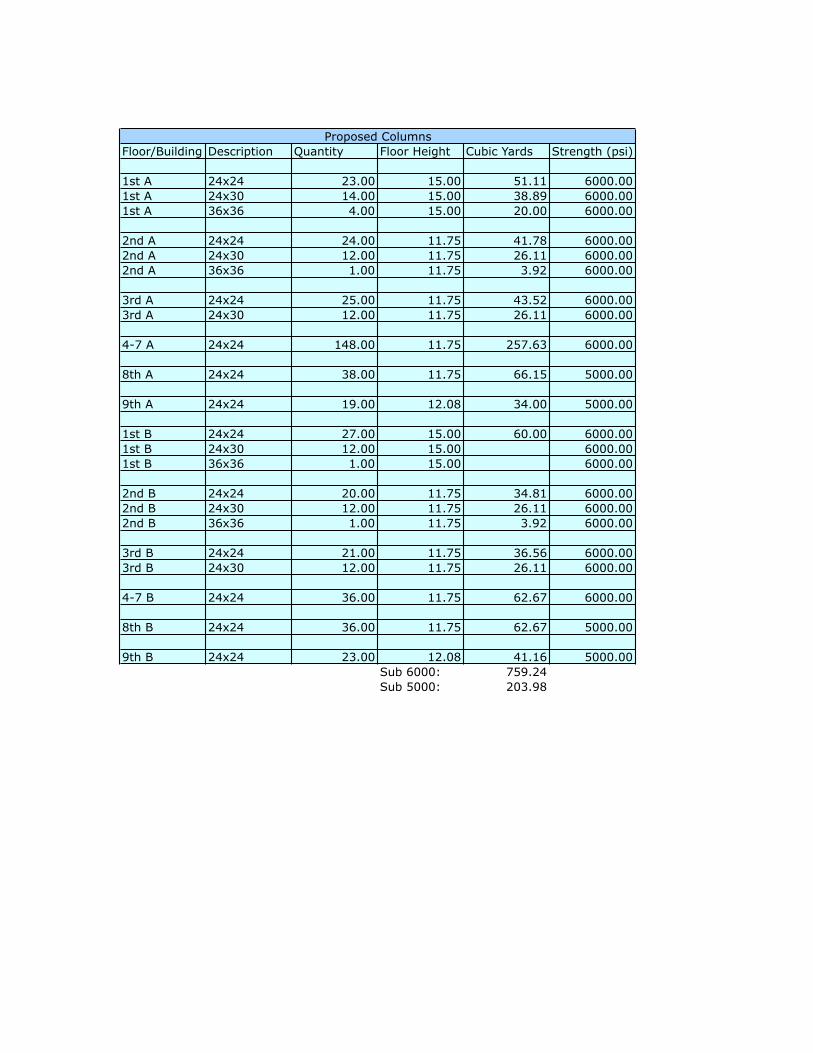
Floor/Building Description Quantity Floor Height Cubic Yards Strength (psi)
1st A 24x24 23.00 15.00 51.11 6000.001st A 24x30 14.00 15.00 38.89 6000.001st A 36x36 4.00 15.00 20.00 6000.00
2nd A 24x24 24.00 11.75 41.78 6000.002nd A 24x30 12.00 11.75 26.11 6000.002nd A 36x36 1.00 11.75 3.92 6000.00
3rd A 24x24 25.00 11.75 43.52 6000.003rd A 24x30 12.00 11.75 26.11 6000.00
4-7 A 24x24 148.00 11.75 257.63 6000.00
8th A 24x24 38.00 11.75 66.15 5000.00
9th A 24x24 19.00 12.08 34.00 5000.00
1st B 24x24 27.00 15.00 60.00 6000.001st B 24x30 12.00 15.00 6000.001st B 36x36 1.00 15.00 6000.00
2nd B 24x24 20.00 11.75 34.81 6000.002nd B 24x30 12.00 11.75 26.11 6000.002nd B 36x36 1.00 11.75 3.92 6000.00
3rd B 24x24 21.00 11.75 36.56 6000.003rd B 24x30 12.00 11.75 26.11 6000.00
4-7 B 24x24 36.00 11.75 62.67 6000.00
8th B 24x24 36.00 11.75 62.67 5000.00
9th B 24x24 23.00 12.08 41.16 5000.00Sub 6000: 759.24Sub 5000: 203.98
Proposed Columns

Potomac Yard Land Bay E
Final Report 81
14 Appendix O:

IDT
ask
Nam
eD
urat
ion
Sta
rtF
inis
h
1V
AV
Sy
ste
m10
2 d
ays
Mo
n 2
/2/0
9T
ue
6/2
3/09
2B
uild
ing
B80
day
sM
on
2/2
/09
Fri
5/2
2/09
32n
d F
loor
Duc
twor
k an
d V
AV
10 d
ays
Mon
2/2
/09
Fri
2/13
/09
43r
d F
loor
Duc
twor
k an
d V
AV
10 d
ays
Mon
2/1
6/09
Fri
2/27
/09
54t
h F
loor
Duc
twor
k an
d V
AV
10 d
ays
Mon
3/2
/09
Fri
3/13
/09
65t
h F
loor
Duc
twor
k an
d V
AV
10 d
ays
Mon
3/1
6/09
Fri
3/27
/09
76t
h F
loor
Duc
twor
k an
d V
AV
10 d
ays
Mon
3/3
0/09
Fri
4/10
/09
87t
h F
loor
Duc
twor
k an
d V
AV
10 d
ays
Mon
4/1
3/09
Fri
4/24
/09
98t
h F
loor
Duc
twor
k an
d V
AV
10 d
ays
Mon
4/2
7/09
Fri
5/8/
0910
9th
Flo
or D
uctw
ork
and
VA
V10
day
sM
on 5
/11/
09F
ri 5/
22/0
911
Bu
ildin
g A
80 d
ays
We
d 3
/4/0
9T
ue
6/2
3/09
122n
d F
loor
Duc
twor
k an
d V
AV
10 d
ays
Wed
3/4
/09
Tue
3/1
7/09
133r
d F
loor
Duc
twor
k an
d V
AV
10 d
ays
Wed
3/1
8/09
Tue
3/3
1/09
144t
h F
loor
Duc
twor
k an
d V
AV
10 d
ays
Wed
4/1
/09
Tue
4/1
4/09
155t
h F
loor
Duc
twor
k an
d V
AV
10 d
ays
Wed
4/1
5/09
Tue
4/2
8/09
166t
h F
loor
Duc
twor
k an
d V
AV
10 d
ays
Wed
4/2
9/09
Tue
5/1
2/09
177t
h F
loor
Duc
twor
k an
d V
AV
10 d
ays
Wed
5/1
3/09
Tue
5/2
6/09
188t
h F
loor
Duc
twor
k an
d V
AV
10 d
ays
Wed
5/2
7/09
Tue
6/9
/09
199t
h F
loor
Duc
twor
k an
d V
AV
10 d
ays
Wed
6/1
0/09
Tue
6/2
3/09
20 21C
hill
ed
Be
am S
yst
em
157
day
sM
on
2/2
/09
Tu
e 9
/8/0
922
Bu
ildin
g B
144
day
sM
on
2/2
/09
Th
u 8
/20/
0923
2nd
Flo
or D
uctw
ork
2 da
ysM
on 2
/2/0
9T
ue 2
/3/0
924
2nd
Flo
or P
ipin
g14
day
sM
on 2
/2/0
9T
hu 2
/19/
0925
2nd
Flo
or B
eam
s4
days
Fri
2/20
/09
Wed
2/2
5/09
263r
d F
loor
Duc
twor
k2
days
Wed
2/4
/09
Thu
2/5
/09
273r
d F
loor
Pip
ing
14 d
ays
Thu
2/2
6/09
Tue
3/1
7/09
283r
d F
loor
Bea
ms
4 da
ysW
ed 3
/18/
09M
on 3
/23/
0929
4th
Flo
or D
uctw
ork
2 da
ysF
ri 2/
6/09
Mon
2/9
/09
304t
h F
loor
Pip
ing
14 d
ays
Tue
3/2
4/09
Fri
4/10
/09
314t
h F
loor
Bea
ms
4 da
ysM
on 4
/13/
09T
hu 4
/16/
0932
5th
Flo
or D
uctw
ork
2 da
ysT
ue 2
/10/
09W
ed 2
/11/
0933
5th
Flo
or P
ipin
g14
day
sF
ri 4/
17/0
9W
ed 5
/6/0
934
5th
Flo
or B
eam
s4
days
Thu
5/7
/09
Tue
5/1
2/09
356t
h F
loor
Duc
twor
k 2
days
Thu
2/1
2/09
Fri
2/13
/09
366t
h F
loor
Pip
ing
14 d
ays
Wed
5/1
3/09
Mon
6/1
/09
376t
h F
loor
Bea
ms
4 da
ysT
ue 6
/2/0
9F
ri 6/
5/09
387t
h F
loor
Duc
twor
k 2
days
Mon
2/1
6/09
Tue
2/1
7/09
397t
h F
loor
Pip
ing
14 d
ays
Mon
6/8
/09
Thu
6/2
5/09
407t
h F
loor
Bea
ms
4 da
ysF
ri 6/
26/0
9W
ed 7
/1/0
941
8th
Flo
or D
uctw
ork
2 da
ysW
ed 2
/18/
09T
hu 2
/19/
0942
8th
Flo
or P
ipin
g14
day
sT
hu 7
/2/0
9T
ue 7
/21/
0943
8th
Flo
or B
eam
s4
days
Wed
7/2
2/09
Mon
7/2
7/09
449t
h F
loor
Duc
twor
k 2
days
Fri
2/20
/09
Mon
2/2
3/09
459t
h F
loor
Pip
ing
14 d
ays
Tue
7/2
8/09
Fri
8/14
/09
469t
h F
loor
Bea
ms
4 da
ysM
on 8
/17/
09T
hu 8
/20/
0947
Bu
ildin
g A
152
day
sM
on
2/9
/09
Tu
e 9
/8/0
948
2nd
Flo
or D
uctw
ork
3 da
ysM
on 2
/9/0
9W
ed 2
/11/
0949
2nd
Flo
or P
ipin
g15
day
sM
on 2
/9/0
9F
ri 2/
27/0
950
2nd
Flo
or B
eam
s4
days
Mon
3/2
/09
Thu
3/5
/09
513r
d F
loor
Duc
twor
k3
days
Thu
2/1
2/09
Mon
2/1
6/09
523r
d F
loor
Pip
ing
15 d
ays
Fri
3/6/
09T
hu 3
/26/
0953
3rd
Flo
or B
eam
s4
days
Fri
3/27
/09
Wed
4/1
/09
544t
h F
loor
Duc
twor
k 3
days
Tue
2/1
7/09
Thu
2/1
9/09
554t
h F
loor
Pip
ing
15 d
ays
Thu
4/2
/09
Wed
4/2
2/09
564t
h F
loor
Bea
ms
4 da
ysT
hu 4
/23/
09T
ue 4
/28/
0957
5th
Flo
or D
uctw
ork
3 da
ysF
ri 2/
20/0
9T
ue 2
/24/
0958
5th
Flo
or P
ipin
g15
day
sW
ed 4
/29/
09T
ue 5
/19/
0959
5th
Flo
or B
eam
s4
days
Wed
5/2
0/09
Mon
5/2
5/09
606t
h F
loor
Duc
twor
k 3
days
Wed
2/2
5/09
Fri
2/27
/09
616t
h F
loor
Pip
ing
15 d
ays
Tue
5/2
6/09
Mon
6/1
5/09
626t
h F
loor
Bea
ms
4 da
ysT
ue 6
/16/
09F
ri 6/
19/0
963
7th
Flo
or D
uctw
ork
3 da
ysM
on 3
/2/0
9W
ed 3
/4/0
964
7th
Flo
or P
ipin
g15
day
sM
on 6
/22/
09F
ri 7/
10/0
965
7th
Flo
or B
eam
s4
days
Mon
7/1
3/09
Thu
7/1
6/09
668t
h F
loor
Duc
twor
k 3
days
Thu
3/5
/09
Mon
3/9
/09
678t
h F
loor
Pip
ing
15 d
ays
Fri
7/17
/09
Thu
8/6
/09
688t
h F
loor
Bea
ms
4 da
ysF
ri 8/
7/09
Wed
8/1
2/09
699t
h F
loor
Duc
twor
k 3
days
Tue
3/1
0/09
Thu
3/1
2/09
709t
h F
loor
Pip
ing
15 d
ays
Thu
8/1
3/09
Wed
9/2
/09
719t
h F
loor
Bea
ms
4 da
ysT
hu 9
/3/0
9T
ue 9
/8/0
9
WT
FS
SM
TW
TF
SS
MT
WT
FS
SM
TW
TF
SS
MT
WT
Jan
25, '
09F
eb 1
5, '0
9M
ar 8
, '09
Mar
29,
'09
Apr
19,
'09
May
10,
'09
May
31,
'09
Jun
21, '
09Ju
l 12,
'09
Aug
2, '
09A
ug 2
3, '0
9S
ep
Tas
k
Spl
it
Pro
gres
s
Mile
ston
e
Sum
mar
y
Pro
ject
Sum
mar
y
Ext
erna
l Tas
ks
Ext
erna
l Mile
ston
e
Dea
dlin
e
Pag
e 1
Pro
ject
: Chi
lled
Bea
m V
AV
Com
paris
onD
ate:
Tue
3/3
0/10