The Outrigger: A Prehistoric Feedback Mechanismdabramovitch.com/pubs/OutriggerCDC2003.pdfThe...
10
The Outrigger: A Prehistoric Feedback Mechanism Daniel Abramovitch Agilent Laboratories Communications and Optics Research Lab 3500 Deer Creek Road, M/S: 25U-9 Palo Alto, CA 94304 Phone: (650) 485-3806 FAX: (650) 485-4080 E-mail: [email protected] Abstract— “How does that work?” asked DJ, my 3 year old son. We were standing on the beach at Waikiki, looking at an outrigger canoe. He was pointing to the outrigger. Like any dutiful father, I started trying to explain the use of the outrigger. Halfway through my explanation, I realized that I was describ- ing a feedback mechanism. A cursory knowledge of Polynesian history indicated that this was an ancient mechanism, quite possibly the first feedback mechanism created by humanity, predating the float valve by at least a millennium. This paper is my attempt to chronicle the history of this remarkable bit of Stone Age control engineering. I. I NTRODUCTION Fig. 1. The outrigger canoe on the beach. There are two types of floating watercraft: those that owe their buoyancy to the material from which they are made, and those that owe their buoyancy to the amount of water that they displace. While the reed boats of Ancient Egypt and the balsa rafts of Peru are in the former class [1], the dugout canoe so prevalent in Polynesia belongs to the latter class [2]. The dugout canoe suffers from a tendency to capsize, as compared to plank-built vessels (vessels built of planks attached to some frame). Unlike the latter, there is limited ability to increase a dugout’s resistance to capsizing (i.e. to increase its roll stability) by widening or changing the shape of the keel. Thus, the dugout canoe begs for a different solution to the roll stability problem. At its most basic level, an outrigger consists of some sort of a float, attached via one or more booms to the gunwales (top edge) of a boat. While modern outriggers can be made from a variety of sturdy, buoyant materials, the outrigger float has traditionally been some piece of light wood, and the type of boat that it is most often associated with is a dugout canoe. However, outriggers are also found on plank-built boats, although the necessity is lessened for these vessels. Builders of plank boats have more ability to improve roll stability by changing the hull shape than makers of dugout canoes. The action of an outrigger is twofold. First, it adds buoyancy to the vessel, since outriggers are made of materials that float irrespective of their shapes. More importantly, the addition of a float at the end of the boom dramatically increases the roll stability of the small canoes to which outriggers are typically attached. Until the publication of Otto Mayr’s The Origins of Feedback Control [3], [4], the consensus among control engineers was that the original feedback mechanism built by human beings was Watt’s flyball governor [5]. However, Mayr’s work established convincing evidence that the water clock of Ktesibios who lived in Alexandria “in the first half of the third century B.C.” was the first recorded feedback mechanism [3]. This predated the flyball governor by two millenia. A series of other devices based on the float valve, followed in the succeeding centuries, most of these appearing in the Middle East. Otto Mayr’s book also established a set of criteria to determine if a device was in fact a feedback mechanism [3]. The three criteria we have now obtained contain a sufficiently complete definition of the concept. Briefly repeated, they are: 1) The purpose of a feedback control system is to carry out commands; the system maintains the controlled variable equal to the command signal in spite of external disturbances.
Transcript of The Outrigger: A Prehistoric Feedback Mechanismdabramovitch.com/pubs/OutriggerCDC2003.pdfThe...

The Outrigger: A Prehistoric Feedback Mechanism
Daniel AbramovitchAgilent Laboratories
Communications and Optics Research Lab3500 Deer Creek Road, M/S: 25U-9
Palo Alto, CA 94304Phone: (650) 485-3806FAX: (650) 485-4080
E-mail: [email protected]
Abstract— “How does that work?” asked DJ, my 3 year oldson. We were standing on the beach at Waikiki, looking atan outrigger canoe. He was pointing to the outrigger. Like anydutiful father, I started trying to explain the use of the outrigger.Halfway through my explanation, I realized that I was describ-ing a feedback mechanism. A cursory knowledge of Polynesianhistory indicated that this was an ancient mechanism, quitepossibly the first feedback mechanism created by humanity,predating the float valve by at least a millennium. This paperis my attempt to chronicle the history of this remarkable bit ofStone Age control engineering.
I. INTRODUCTION
Fig. 1. The outrigger canoe on the beach.
There are two types of floating watercraft: those that owetheir buoyancy to the material from which they are made,and those that owe their buoyancy to the amount of waterthat they displace. While the reed boats of Ancient Egyptand the balsa rafts of Peru are in the former class [1],the dugout canoe so prevalent in Polynesia belongs to thelatter class [2]. The dugout canoe suffers from a tendencyto capsize, as compared to plank-built vessels (vessels builtof planks attached to some frame). Unlike the latter, there is
limited ability to increase a dugout’s resistance to capsizing(i.e. to increase its roll stability) by widening or changing theshape of the keel. Thus, the dugout canoe begs for a differentsolution to the roll stability problem.
At its most basic level, an outrigger consists of some sortof a float, attached via one or more booms to the gunwales(top edge) of a boat. While modern outriggers can be madefrom a variety of sturdy, buoyant materials, the outrigger floathas traditionally been some piece of light wood, and the typeof boat that it is most often associated with is a dugout canoe.However, outriggers are also found on plank-built boats,although the necessity is lessened for these vessels. Buildersof plank boats have more ability to improve roll stability bychanging the hull shape than makers of dugout canoes. Theaction of an outrigger is twofold. First, it adds buoyancy tothe vessel, since outriggers are made of materials that floatirrespective of their shapes. More importantly, the addition ofa float at the end of the boom dramatically increases the rollstability of the small canoes to which outriggers are typicallyattached.
Until the publication of Otto Mayr’s The Origins ofFeedback Control [3], [4], the consensus among controlengineers was that the original feedback mechanism builtby human beings was Watt’s flyball governor [5]. However,Mayr’s work established convincing evidence that the waterclock of Ktesibios who lived in Alexandria “in the first halfof the third century B.C.” was the first recorded feedbackmechanism [3]. This predated the flyball governor by twomillenia. A series of other devices based on the float valve,followed in the succeeding centuries, most of these appearingin the Middle East.
Otto Mayr’s book also established a set of criteria todetermine if a device was in fact a feedback mechanism [3].
The three criteria we have now obtainedcontain a sufficiently complete definition of theconcept. Briefly repeated, they are:
1) The purpose of a feedback control system isto carry out commands; the system maintainsthe controlled variable equal to the commandsignal in spite of external disturbances.
2) The system operates as a closed loop withnegative feedback.
3) The system includes a sensing element and acomparator, at least one of which can be dis-tinguished as a physically separate element.
Using these criteria, this paper will argue that the outriggeron an outrigger canoe, the device that Heyerdahl referredto as “the most desirable of the Asiatic navigational inven-tions ([1],pp. 160–161)”, is in fact a feedback mechanism.Furthermore, this device predates the float valve by at leasta thousand years, making it the earliest feedback mechanismbuilt by humans to be documented thus far.
The organization of this paper is as follows. Section IIgives a cursory explanation of the dynamics of boat stability.Section III, discusses the use of an outrigger in providing rollstability for a dugout canoe. Section IV gives a qualitativedescription of the operation of an outrigger, specificallyhow it satisfies the Mayr criteria of a feedback mechanism.Section V delves into the origins of the outrigger and tracesits progression around the world.
II. BASIC ROLL STABILITY
CGB
CGB
CG
B
a
CGB
CG
B
a
A B C
FGFG
FBFB
Fig. 2. Righting moment for a typical plank boat hull. (Reproducedfrom [6], p. 252.)
A key component of any watercraft is its roll stability. Putsimply, a watercraft with poor roll stability will capsize eas-ily. If the craft is made of heavier-than-water materials, thenit relies on the displacement of water to achieve buoyancy. Insuch a situation, capsizing leads to the waterlogging of thevessel, which in turn leads to it sinking. Even for watercraftmade of buoyant materials, capsizing puts people and cargoin the water.
Resistance to capsizing, or roll stability comes from havinga righting moment that resists angular disturbances. Considerthe typical plank-built boat cross section in Figure 2. The boatfloats because it displaces water equivalent to its weight. Aslong as the boat can displace more water than its weight,it will be buoyant. For most boats with bilateral symmetryabout the center line, this means that the center of gravityis above the center of buoyancy (Figure 2A). When the boatrotates around its center of gravity (Figure 2B), the center ofbuoyancy moves out from under the center of gravity, result-ing in a moment opposing the rotation equal to [FG + FB ] a.
MR MR,MAX
�
90o
45o
0o
Fig. 3. A typical righting moment curve. The righting moment increaseswith increasing angle until some maximum value, MR,MAX .
CG
B
CG
BCG
B
CG
B
aa
A B C D
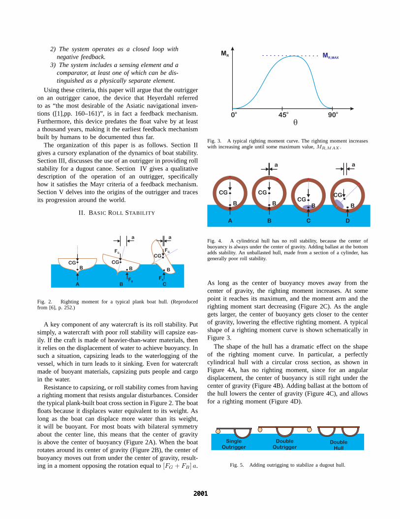
Fig. 4. A cylindrical hull has no roll stability, because the center ofbuoyancy is always under the center of gravity. Adding ballast at the bottomadds stability. An unballasted hull, made from a section of a cylinder, hasgenerally poor roll stability.
As long as the center of buoyancy moves away from thecenter of gravity, the righting moment increases. At somepoint it reaches its maximum, and the moment arm and therighting moment start decreasing (Figure 2C). As the anglegets larger, the center of buoyancy gets closer to the centerof gravity, lowering the effective righting moment. A typicalshape of a righting moment curve is shown schematically inFigure 3.
The shape of the hull has a dramatic effect on the shapeof the righting moment curve. In particular, a perfectlycylindrical hull with a circular cross section, as shown inFigure 4A, has no righting moment, since for an angulardisplacement, the center of buoyancy is still right under thecenter of gravity (Figure 4B). Adding ballast at the bottom ofthe hull lowers the center of gravity (Figure 4C), and allowsfor a righting moment (Figure 4D).
SingleOutrigger
DoubleOutrigger
DoubleHull
Fig. 5. Adding outrigging to stabilize a dugout hull.

One possibility for adding a righting moment to a cylin-drical hull is to attach it to a second cylindrical hull. Thefarther apart the two hulls, the easier it is to generate arighting moment (at least for small angles). This can be donein one of several ways. Here we will concentrate on the threemethods most closely associated with outrigger technology: asingle outrigger, a double outrigger, and a double hull canoe,shown in Figure 5. We will see that all three are present inthe sailing technology of the Austronesian peoples1. They allwork on similar principles. The trade-offs in choosing onetype of watercraft over another seem to have more to do withease of manufacture, structural safety, and crew requirementsfor each type of craft.
Qualitatively, the operation of the outrigger is rather sim-ple. When the canoe rotates so as to raise the boom fromthe water, its weight at the end of a moment arm providestorque to rotate the boom back to the surface. When therotation of the canoe acts to push the boom into the water,the buoyancy of the boom acts to restore the boom to thesurface of the water. In other words, it senses and resistsangular disturbances – truly a negative feedback mechanism.
III. THE DUGOUT CANOE
(a)
(b)
Fig. 6. Comparison of plank built (a) versus outrigger (b) canoe. Note thenarrow hull of the outrigger as compared with the plank built hull.
CG
B
A
Fb
mgB
L
Fig. 7. An unballasted hull, made from a section of a cylinder, has generallypoor roll stability. This is the case for the dugout canoe on the left. Addingan outrigger, on the right, creates a righting moment.
This section will present a simplified static analysis of adugout canoe, showing the effect of adding an outrigger. The
1The term Austronesian is used by Doran [7] and others to describe thegeneral set of people that moved out of Asia to Australia and into thePacific. The name denotes a superset of the indigenous peoples of Australia,Indonesia, Malaysia, and Polynesia
buoyant forces for various simple shapes of outrigger floatsas a function of change in dept will be presented to showthe development of righting moments.
A pictorial comparision of plank built and outrigger canoescan be seen in Figure 6. Unlike a plank-built boat, a dugoutcanoe is hollowed out of a single tree trunk. This limitsthe shape of the cross section to something that closelyfollows a portion of a cylinder. This has a very small inherentrighting moment, as shown in Figure 7A. In other words, theroll stability is poor. However, the addition of an outrigger(Figure 7B) improves this situation considerably. From afeedback perspective, the outrigger adds a righting moment.In Figure 7B, the float has a nominal depth of d at whichthe buoyant force exactly cancels the force of gravity, i.e.FB(d) = mg. For a disturbance that moves the depth awayfrom the nominal by ∆d,
MR(∆d) = [FB(d + ∆d) − mg] a (1)
= [FB(d + ∆d) − FB(d)] a. (2)
Computing the righting moment for different configurationsessentially consists of computing FB(d + ∆d)−FB(d). Fora rotation of the main hull through an angle θ, the change indepth, ∆d, is found by
∆d = L sin θ, (3)
while the moment arm of the buoyant force, a, is given by
a = L cos θ. (4)
This linearizes for small θ to
∆d = Lθ and a = L. (5)
mg
Fb
d
RectangularFloat
mg
Fb
d�
TriangularFloat
mg
Fb
d
r
CircularFloat
Fig. 8. Different float shapes yield different error equations.
It is rather straightforward, albeit tedious to compute thebuoyant forces for different float cross sections. This is donein detail in the Appendix, while results are presented here.For all of these cross sections, the equations generated arein terms of the nominal depth of the float, d, the change indepth, ∆d, and the float geometry. In these results, l is thelength of the float, ρ is the density of the displaced water,and g is the acceleration due to gravity.
The first shape is the rectangular float, shown on the leftside of Figure 8. This is the simplest to compute and is theone that gives a linear error equation, that is the resultantbuoyant force as a result of the vertical displacement, ∆d, is
F∆d = ρg∆d. (6)

A more likely pair of shapes for a float is one with atriangular cross section or a circular cross section, at thecenter and right of Figure 8, respectively.
For the cross section in the shape of an isosceles triangle,we would like to calculate the buoyancy as a function of thedepth of the section, d. In this case the difference in forcesis given by
Fb(d + ∆d) − Fb(d)= [Vimm(d + ∆d) − Vimm(d)] ρg (7)
= l [Ad+∆d − Ad] ρg (8)
= l(2d∆d + (∆d)2) tanθ
2ρg, (9)
where θ is the angle of the triangle corner in the water. Now,the feedback term is dependent upon the nominal depth, d,and has a quadratic component.
If we repeat the same set of calculations for the circularcross sectional float, we must calculate the area of thesubmerged segment as a function of the radius, r, and thedepth, d. This results in a difference in forces equal to
Fb(r, d + ∆d) − Fb(r, d)
= l
[(r2Cos−1 r − (d + ∆d)
r−
(r − (d + ∆d))√
2r(d + ∆d) − (d + ∆d)2)−(
r2Cos−1 r − d
r− (r − d)
√2rd − d2
)]ρg. (10)
For small ∆d, Equations 9 and 10 both become linear in ∆d,which matches physical intuition.
IV. THE OUTRIGGER AS A FEEDBACK MECHANISM
The outrigger may have evolved from the custom oflashing two canoes together to provide greater roll stability.However, at first blush the double hulled canoe does notseem to qualify as a feedback mechanism since the secondhull does more than just provide roll stability. First of all,unlike the outrigger, it is hard to distinguish which hull isthe feedback mechanism and which hull is the main part ofthe boat. The second hull also increases the cargo capacityof the ship, and gives it more length in the water whichdecreases the wake and improves the speed [6],pp: 255–257.The outrigger itself provides no such extra capacity and thusits chief purpose is that of roll stability.
From the perspective of the Mayr criteria, the outriggersatisfies all three:
1) The outrigger provides roll stability for thecanoe. That is, it keeps the canoe from capsizing.In this respect, the controlled variable is the anglebetween the bottom of the canoe and the surfaceof the water.
2) The outrigger provides negative feedback.From a nominal position on the water, the buoy-ancy resists rotations that would further submerge
the outrigger and the weight resists rotations thatwould raise it out of the water.
3) The outrigger itself is a separate elementfrom the canoe. It is the sensing element and theactuator for detecting and correcting rotations. Itsonly purpose is to provide roll stability.
The double outrigger makes the stabilization problem sym-metric by putting a buoyant float on either side of the hull.The double hulled canoe also makes the problem symmetric,by adding a second hull in parallel to the first. Returning to astrict interpretation of the Otto Mayr criteria, the second hullmight not be considered a feedback mechanism. However,the double hull canoe is an obvious member of the outriggerfamily, springing from the same culture and used in parallelwith the outrigger canoes. Viewed in the context of otheroutriggers the double hull should be seen as a stabilizationdevice. Thus, we consider all three forms to be instances ofoutrigger technology. As such, the age of one over another isnot critical to understanding the age of outrigger technology,but is useful to study.
V. THE ORIGINS AND HISTORY OF OUTRIGGER CANOES
Fig. 9. Mural depicting ancient Polynesian voyaging canoe in the lobbyof the Outrigger Waikiki Hotel.
Debates about the origins of outrigger technology are inti-mately connected to debates about who originally populatedthe South Seas, and when and how they did it. Central to bothdebates are questions about the seaworthiness of Polynesiancanoes and the skills of Polynesian sailors. The absence ofwritten records and scarcity of material remains of canoesfueled the debates2.
The traditional view of Polynesian migration, island hop-ping across the Pacific in deliberate exploration, was codifiedby Peter Buck in his classic book, Vikings of Sunrise, later
2The ancient Polynesians had no written language. Furthermore, therewere no traces of the ancient canoes as they were made of soft woodswhich would swiftly decompose in the warm waters of the South Pacificand Indian Oceans.
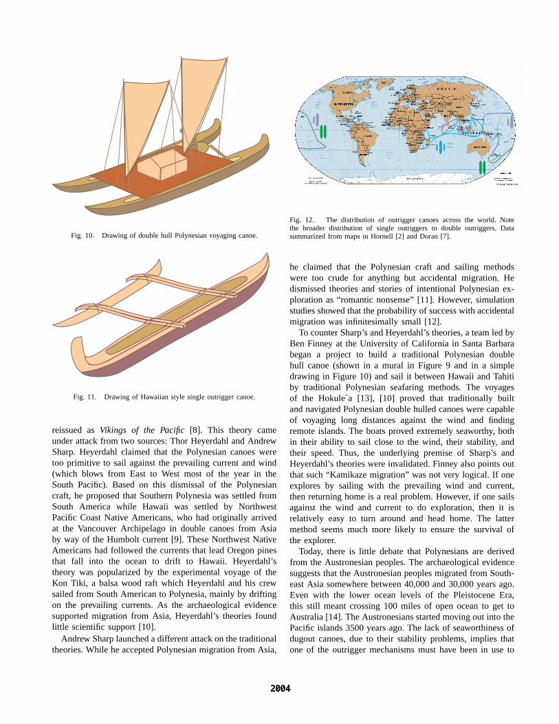
Fig. 10. Drawing of double hull Polynesian voyaging canoe.
Fig. 11. Drawing of Hawaiian style single outrigger canoe.
reissued as Vikings of the Pacific [8]. This theory cameunder attack from two sources: Thor Heyerdahl and AndrewSharp. Heyerdahl claimed that the Polynesian canoes weretoo primitive to sail against the prevailing current and wind(which blows from East to West most of the year in theSouth Pacific). Based on this dismissal of the Polynesiancraft, he proposed that Southern Polynesia was settled fromSouth America while Hawaii was settled by NorthwestPacific Coast Native Americans, who had originally arrivedat the Vancouver Archipelago in double canoes from Asiaby way of the Humbolt current [9]. These Northwest NativeAmericans had followed the currents that lead Oregon pinesthat fall into the ocean to drift to Hawaii. Heyerdahl’stheory was popularized by the experimental voyage of theKon Tiki, a balsa wood raft which Heyerdahl and his crewsailed from South American to Polynesia, mainly by driftingon the prevailing currents. As the archaeological evidencesupported migration from Asia, Heyerdahl’s theories foundlittle scientific support [10].
Andrew Sharp launched a different attack on the traditionaltheories. While he accepted Polynesian migration from Asia,
Fig. 12. The distribution of outrigger canoes across the world. Notethe broader distribution of single outriggers to double outriggers. Datasummarized from maps in Hornell [2] and Doran [7].
he claimed that the Polynesian craft and sailing methodswere too crude for anything but accidental migration. Hedismissed theories and stories of intentional Polynesian ex-ploration as “romantic nonsense” [11]. However, simulationstudies showed that the probability of success with accidentalmigration was infinitesimally small [12].
To counter Sharp’s and Heyerdahl’s theories, a team led byBen Finney at the University of California in Santa Barbarabegan a project to build a traditional Polynesian doublehull canoe (shown in a mural in Figure 9 and in a simpledrawing in Figure 10) and sail it between Hawaii and Tahitiby traditional Polynesian seafaring methods. The voyagesof the Hokule`a [13], [10] proved that traditionally builtand navigated Polynesian double hulled canoes were capableof voyaging long distances against the wind and findingremote islands. The boats proved extremely seaworthy, bothin their ability to sail close to the wind, their stability, andtheir speed. Thus, the underlying premise of Sharp’s andHeyerdahl’s theories were invalidated. Finney also points outthat such “Kamikaze migration” was not very logical. If oneexplores by sailing with the prevailing wind and current,then returning home is a real problem. However, if one sailsagainst the wind and current to do exploration, then it isrelatively easy to turn around and head home. The lattermethod seems much more likely to ensure the survival ofthe explorer.
Today, there is little debate that Polynesians are derivedfrom the Austronesian peoples. The archaeological evidencesuggests that the Austronesian peoples migrated from South-east Asia somewhere between 40,000 and 30,000 years ago.Even with the lower ocean levels of the Pleistocene Era,this still meant crossing 100 miles of open ocean to get toAustralia [14]. The Austronesians started moving out into thePacific islands 3500 years ago. The lack of seaworthiness ofdugout canoes, due to their stability problems, implies thatone of the outrigger mechanisms must have been in use to

make this possible. This pins the minimum age of outriggertechnology at 3500 years. It is quite possibly associated withthe migration to Australia, which would make it considerablyolder [14].
Another piece of evidence is in the migration from Asiato Polynesia. The Polynesians used both outrigger canoes(Figure 11) and double canoes, with the the latter beingthe primary vessel for long range exploration [13]. Finneypoints out [13] that the Polynesian culture itself is necessarilya seafaring culture: “Polynesian culture developed not inany Asian or American homeland, but in Polynesia itself.Seafarers ancestral to the Polynesians moved from easternMelanesia to the uninhabited islands of Tonga and Samoabetween 1500 and 100 B.C. They settled there, and overthe centuries the basic Polynesian cultural pattern developed.Starting about the time of Christ, seafarers, full-fledged Poly-nesians now, moved from these western Polynesia centers tothe east to settle first probably the Marquesas Islands and thenthe Society Islands (the most important of which is Tahiti).”
Stanley also places the origins of Polynesian migration ataround 1500-1600 B.C: “Sometime after about 1600 B.C.,broad-nosed, light-skinned Austronesian peoples entered thePacific from Indonesia or the Philippines. . . . Three thousandfive hundred years ago, the early Polynesians set out fromSoutheast Asia on a migratory trek that would lead themto make the ‘many islands’ of Polynesia their home. Greatvoyagers, they sailed their huge double-hulled canoes farand wide, steering with huge paddles and pandanus sails.To navigate they read the sun, stars, currents, swells, winds,clouds, and birds. Sailing purposefully, against the prevailingwinds and currents, the Lapita peoples reached the BismarckArchipelago by 1500 B.C., Tonga (via Fiji) by 1300 B.C.,and Samoa by 1000 B.C. Around the time of Christ theypushed out from this primeval area, remembered as Havaiki,into the eastern half of the Pacific [15].”
Given the probable origins of the outrigger in SoutheastAsia and the timing of the migrations into the Pacific, wecan establish that the outrigger likely dates to at least 1500B.C., 1200 years before the the water clock of Ktesibios.
Note that the use of the outrigger spanned most of thePacific and Indian Oceans, from Easter Island and Hawaii inthe east, to Madagascar in the west. Madagascar itself wasfirst settled by Indonesians who crossed the Indian ocean inoutrigger canoes approximately 2000 years ago [2]. To theeast, the primary Polynesian exploration vessel was the dou-ble hulled canoe, ancestor to the modern catamaran [13]. Thesingle outrigger canoe was a technology that they broughtwith them for their smaller craft. One of the main difficultieswith making double hulled canoes was finding two matchinglogs of sufficient size. Among the most prized logs for canoebuilding were Oregon pines that fell into the ocean anddrifted to Hawaii. They were so valued that logs would bekept for years until a matching one drifted ashore [2], [9].The outrigger provided equivalent roll stability for a canoe
made of only one large log.Heyerdahl also points out differences between different
types of outrigger canoes:
All through Indonesia, from Sumatra and thePhilippines to the nearest tip of New Guinea, theMalays and Indonesians have since early timesused the double outrigger to stabilize their craft,i.e., a buoyant boom fastened to crossbars oneach side of the vessel. The Micronesians and theMelanesians used a single outrigger, that is on oneside only, and for this reason the Micronesiansbuilt their canoes laterally asymmetrical. When thePolynesians adopted the single outrigger on theirbilaterally symmetrical canoes they did not followthe Micronesian model but followed that of neigh-boring Fiji. In short, neither the Indonesian northe Micronesian type of outrigger canoe reachedthe East Pacific [1] (pp. 160–161).
Where each style of outrigger first appeared is a matterof some debate. Much of the source material on outriggercanoes comes from work by James Hornell, an official whoworked in British India in the early part of the twentiethcentury. Hornell’s joint work with A. C. Haddon [16] re-mains the definitive source book for most research in thisarea. Many of the boats documented in the three volumesof Canoes of Oceania have passed from existence sincethe book was written in the 1940s. After his retirement,Hornell traveled the world to document the development ofwatercraft [2]. Although there has been more recent work onthe subject, the source material often includes Hornell andHaddon’s work, since the disappearance of many of thesewatercraft in the past hundred years have made their booksthe main documentation on the vessels. One of the morerecent studies was done by Edwin Doran. Doran lookedat this same source evidence with more modern methodsand came to opposite conclusions about the relative ages ofdifferent outriggers in his book, Wangka: Austronesian CanoeOrigins [7]. Section V-A will discuss Hornell’s view whileSection V-B will present Doran’s.
A. Hornell’s View
Outrigger canoes are closely associated with Indonesia.Hornell lists Indonesia as the center of dispersal of theoutrigger ([2], pp. 263–269). However, Hornell goes on topoint out that virtually all watercraft technology originatedin rivers and marshes, rather than in the ocean ([2], pp. 264–265). Indonesia, lacking any significant lakes or rivers, isthen a poor candidate for the origins of the outrigger canoe.Evidence is that the settlers of Indonesia migrated down fromSoutheast Asia, and it is this region, with its wide riversthat is the most likely cradle of the outrigger canoe. Hornellsuggests that the Irrawaddy, Salween, and Mekong rivers,which “have been from time immemorial the only highwaysof migration available to the peoples pressing southwards

Fig. 13. Drawing of double outrigger canoe of style found in Indonesia.
from the cold and dreary mountain lands of the north to thefertile lower plains,” as the likely locations. “Nowhere elsecan the development of the dugout canoe into sailing shipsof large size be so clearly traceable, step by step, as on thegreat Burmese river. The dugout in general use by the riverpeople, scattered in innumerable villages along its banks, isthe most beautiful of its class. Hewn by men possessed ofunconscious skill and inborn artistic feeling, the huge teakbaulk is fashioned into a long and relatively narrow craftsheering upwards in a graceful curve toward each end, whereit rises well above the water line like the horns of a giganticcrescent ([2], p. 265).” Hornell goes on to place the originaloutrigger craft at double outrigger with bamboo trunks forfloats [2],(p. 266).
From these rivers, the migration to Indonesia was madenecessarily by watercraft. Thus, for the outrigger to appearin Indonesia, it must have been used in the migration fromSoutheast Asia. Heyerdahl indicates that “outriggers [were]used on local proas3 in Southeast Asia since the secondmillennium B.C. ([9], p. 64).”
The outriggers of Indonesia typically have double outrig-gers, that is, they have an outrigger on each side of thecanoe [2]. This is diagrammed in Figure 13, which is basedon images in Adrian Horridge’s book [17]. Hornell attributes
3A type of Asian boat.
this to the relatively sheltered waters of the Indonesianarchipelago. As outriggers moved into more open water, thesingle outrigger was structurally safer. By comparison, thedouble outrigger stands a good chance of suspending themain hull from the outriggers in heavy seas.
B. Doran’s View
Doran’s work [7] debates the theory of the seaworthinessof the double outrigger and the notion that it is the earlierversion of the technology. Doran bases his analysis on disper-sal patterns centered on Indonesia. He claims that the doublecanoe preceded the single outrigger, which in turn precededthe double outrigger. He claims that Hornell’s arguments ofdouble outriggers being less seaworthy than single outriggersare poorly supported by any actual evidence. Instead, theevidence points to the seaworthiness of double outriggers, asthey spread into areas that already had single outriggers.
He makes the case that the geographic extent of doubleoutrigger canoes, being a subset of the the geographic extentof single outrigger canoes, indicates that it is a later technol-ogy, emanating from the center of invention. (See Figure 12.)Likewise, Doran notes that the practice of shunting ratherthan tacking – used in Micronesian single outrigger canoesunder sail – is a later development.
C. Double Hull versus Outrigger
The issue of using a double hulled canoe versus a singlehulled canoe with outrigger can be seen as an issue of ease ofmanufacture, human interface, and capacity. Double canoesrequired two very similar tree trunks to be present. Mostprized for canoe making in Hawaii were Oregon pines thathad fallen into the Pacific and drifted to the islands. In fact, itwas common for a log to be stored for years until a matchingone arrived at the Hawaiian shores [2], [9]. Outrigger canoeshave no such manufacturing issues, since the outrigger willnot have any need to match the main hull.
Double hull canoes were large devices, requiring severalmen to handle properly. Thus, such canoes were inappro-priate for individual use. Outriggers were generally smallenough for a single person to handle.
Finally, it should be noted that the materials used to strapthe two hulls of a double canoe together limited the distancebetween the hulls. These canoes had a much narrower aspectratio than their descendants, the modern catamaran andtrimaran. Generally speaking, the weight and buoyant forceson the second hull of a double hull canoe were large enoughto produce moments to snap the connecting beams if theywere too long. The smaller outrigger booms had much lessweight and buoyant force, and thus could allow for longerbooms.
D. Shunting Versus Tacking
Among the more interesting features of outrigger canoesare the different ways that these canoes were sailed into thewind. While a sailboat cannot sail into the wind directly,

(a) (b) (c)
Wind
Fig. 14. Sailing into the wind: tacking for a sloop (a), wearing for a squarerigger (b), and shunting for an outrigger canoe (c). (From [6], p. 254.)
different sailboats can sail close to the wind – that is – ata diagonal angle into the wind. The issue then becomes oneof how to turn the boat to go on the opposite diagonal asone works against the wind. On a modern sailboat, suchas a sloop, the boat progresses against the wind by tacking(Figure 14a). In this case, the bow of the boat always isangled into the wind. When the boat turns, the sail goesslack as the boom swings to the other side and the windfills the sail again. This does not work for a square riggerwhich at some point in a tack would end up with its sailsbeing pushed backward by the direct wind. Instead, squareriggers are turned by a looping method known as wearing(Figure 14b).
Although most of the outrigger canoe sailing against thewind is done by tacking, there is a subset of the outriggercanoes that employ what is known as shunting (Figure 14c).In order to keep the outrigger on the windward side, theMicronesians sail in one direction and then pull to a stop.Since they don’t want to have the outrigger on the leeward(away from the wind) side, they change the position ofthe sail so that the stern is now the bow (longitudinallysymmetric boat) and then they zag back that way. Havingthe outrigger on the leeward side could cause it to plowinto the ocean and capsize the boat. Thus, a bias force canpush the system out of its stable zone and into a positivefeedback situation. They do the shunting to stay in thenegative feedback region [6].
This is in contrast to tacking. The front of the boat isstill the front of the boat. In tacking, the windward side andleeward side change with every direction change. In the caseof shunting, the bow becomes the stern and the stern becomesthe bow. To do this, they physically move the mast. Thus,the windward side and the leeward side never change.
Shunting is a relatively recent addition to the sailingtechniques. In fact, Doran points out that shunting is done byMicronesians [7], but not by Polynesians, even though bothuse a single outrigger configuration. Malaysians use doubleoutriggers, which makes shunting useless. Likewise, doublecanoes (forbearers of modern catamarans) simply tack [7],
[13].
VI. CONCLUSIONS
Fig. 15. Modern outrigger canoe riding a wave.
When fully considered, the outrigger technology, whetherused as a single outrigger, double outrigger, or a doublehulled canoe, is truly remarkable. By solving the problemof roll stability for dugout canoes, it dramatically increasedthe seaworthiness of these craft, allowing the Austronesianpeople to cross the vast reaches of the Pacific and IndianOceans. This was done by a Stone Age culture with nowritten language, no metal working, and no plank-built boats.As a best estimate, this feedback mechanism predates thewater clock by at least 1000 years. Furthermore, while thewater clock was an interesting exercise, it did not achievea broad penetration into society as a timekeeping device.That task would be performed by the mechanical clock.The outrigger, however, by dramatically increasing the seaworthiness of the Austronesian canoes, bears at least part ofthe responsibility for the broad colonization of islands fromMadagascar to Polynesia, and by that respect, to the veryexistence of the Polynesian people.
ACKNOWLEDGMENTS
This paper would not have happened without the mechan-ical inquisitiveness of my son, D.J. For putting me on thispath, and for many other things, I owe him my gratitudeand parental amazement. In researching the paper, I onceagain got a huge amount of help from the research librariansat Agilent Labs. In particular, Ron Rodriguez was tireless infinding extra references and sources for material on these an-cient devices. I also got a lot of encouragement and assistancein making this paper more legible from Carlene Stephensof the National Museum of American History (NMAH). Ialso appreciate the assistance of Carlene’s colleague, Dr.Paul F. Johnson, Curator of Maritime History at the NMAH,who gave me some excellent pointers to reference materialsand Polynesian migration theories. Dr. Richard Baugh, ofHewlett-Packard Laboratories, who actually builds stone age

tools in his garage, and his wife Marcia also provided somehighly useful references. Terril Hurst, of Hewlett-PackardLaboratories, made his usual strong attempt to improve mywriting style. Finally, I very much appreciate the support ofmy management at Agilent Laboratories for allowing me torepresent the Labs with this work.
VII. REFERENCES
[1] T. Heyerdahl, Early Man and the Ocean: A Search forthe Beginnings of Navigation and Seaborne Civiliza-tions. Garden City, NY: Doubleday & Company, 1979.
[2] J. Hornell, Water Transport: Origins & Early Evolution.London: David & Charles, 1970.
[3] O. Mayr, The Origins of Feedback Control. Cambridge,MA: MIT Press, 1970.
[4] O. Mayr, “The origins of feedback control,” ScientificAmerican, vol. 223, no. 4, pp. 110–118, 1970.
[5] N. Wiener, Cybernetics, Second Edition: or the Controland Communication in the Animal and the Machine.Cambridge, MA: MIT Press, 2nd ed., March 15 1965.
[6] B. Cotterell and J. Kamminga, Mechanics of Pre-Industrial Technology. Cambridge: Cambridge Univer-sity Press, 1990.
[7] E. Doran, Wangka: Austronesian canoe origins. CollegeStation: Texas A & M University Press, 1981.
[8] P. H. Buck, Vikings of the Pacific. Chicago, IL: TheUniversity of Chicago Press, 1959.
[9] T. Heyerdahl, American Indians in the Pacific: The The-ory Behind the Kon-Tiki Expedition. London: GeorgeAllen & Unwin. Ltd., 1952.
[10] B. R. Finney, Voyage of Rediscovery: A CulturalOdyssey Through Polynesia. Berkeley, CA: Universityof California Press, March 1995.
[11] A. Sharp, Ancient Voyagers in the Pacific. Ham-mondsworth, Middlesex, Great Britain: Pengin, 2nd ed.,1957.
[12] G. Irwin, The Prehistoric Exploration and Colinizationof the Pacific. Cambridge, UK: Cambridge UniversityPress, 1992.
[13] B. R. Finney, “Voyaging canoes and the settlement ofPolynesia,” Science, vol. 196, pp. 1277–1285, 1977.
[14] B. Fagan, “Outriggers to the outback,” Archaeology,vol. 43, pp. 16–18, July-August 1990.
[15] D. Stanley, Moon Handbooks Tahiti - Including EasterIsland and the Cooks. Chico, CA: Moon PublicationsInc., fourth ed., May 15 1999.
[16] A. C. Haddon and J. Hornell, Canoes of Oceania.Honolulu, HI: Bishop Museum Press, 1975.
[17] A. Horridge, Outrigger Canoes of Bali and Madura,Indonesia. Honolulu, HI: Bishop Museum Press, 1987.
mg
Fb
d
RectangularFloat
mg
Fb
d�
TriangularFloat
mg
Fb
d
r
CircularFloat
Fig. 16. Different float shapes yield different error equations.
APPENDIX: CALCULATION OF BUOYANT FORCES FOR
VARIOUS FLOAT SHAPES
Qualitatively, the operation of the outrigger is rather sim-ple. When the canoe rotates so as to raise the boom from thewater, it’s weight at the end of a moment arm provides torqueto rotate the boom back to the surface. When the rotation ofthe canoe acts to push the boom into the water, the buoyancyof the boom acts to restore the boom to the surface of thewater.
The buoyancy of the float is easy enough to calculatefor several of the typical shapes. The first of these, therectangular float, on the left side of Figure 16 is the simplestto compute an is the one that gives a linear error equation.
ΣFy = Fb − W = 0. (11)
For a float with a rectangular cross section and area, a, theweight of the float, mg equals the weight of the displacedwater:
Fb = mg = Vimmρg, (12)
where Vimm is the volume of the immersed portion of thefloat, i.e.
Vimm = Abd, (13)
where Ab is the area of the boat bottom, d is the depth ofimmersion, ρ is the density of water, and g is the accelerationdue to gravity.
Now, let’s assume that the depth of the float is disturbedaway from the nominal, d, by ∆d:
ΣFy = Fb − W = F∆d (14)
= ρg(d + ∆d)Ab − mg (15)
= ρgdAb − mg + ρg∆d (16)
Since the first two terms cancel in equilibrium, we arriveat the resultant buoyant force as a result of the verticaldisplacement is
F∆d = ρg∆d. (17)
In other words, the float resists any change away fromequilibrium as expected.
A rectangular cross section on a float is convenient forcalculation as it leads to a linear error equation (Equation 17).However, it is less likely that a triangular cross section or acircular cross section, at the center and right of Figure 16,respectively.

For the cross section in the shape of an isosceles triangle,we would like to calculate the buoyancy as a function of thedepth of the section, d. Applying Equation 12 again, we have
Vimm = Adl, (18)
where l is the length of the float into the page and Ad is thearea of the submerged triangular cross section as a functionof d.
Ad =12bd, (19)
where b is the base of the triangle. We can calculate thisfrom the angle of the submerged corner, θ, and the depth, d,by
tanθ
2=
b2
d(20)
sob = 2d tan
θ
2, (21)
and
Ad =12(2d tan
θ
2)d (22)
= d2 tanθ
2. (23)
Again, we change the depth away from nominal by
Ad+∆d = (d + ∆d)2 tanθ
2, (24)
so that
Ad+∆d − Ad = (2d∆d + (∆d)2) tanθ
2. (25)
Finally,
Fb(d + ∆d) − Fb(d)= [Vimm(d + ∆d) − Vimm(d)] ρg (26)
= l [Ad+∆d − Ad] ρg (27)
= l(2d∆d + (∆d)2) tanθ
2ρg, (28)
where l is the length of the float, θ is the angle of thesubmerged corder, ρ is the density of water, and g isthe acceleration due to gravity. Now, the feedback term isdependent upon the nominal depth, d, and has a quadraticcomponent.
If we repeat the same set of calculations for the circularcross sectional float, we must calculate the area of thesubmerged segment as a function of the radius, r, and thedepth, d.
Asegment(r, d) = r2Cos−1 r − d
r−(r−d)
√2rd − d2. (29)
when the float rises out of the water, we see that as d −→ 0,both the first and second terms tend to 0. The buoyant forceis thus
Fb(r, d) = l
[r2Cos−1 r − d
r− (r − d)
√2rd − d2
]ρg.
(30)If we consider d to be the equilibrium depth for a given floatmaterial and radius, then the force opposing any displace-ment, ∆d, is
Fb(r, d + ∆d) − Fb(r, d)
= l
[(r2Cos−1 r − (d + ∆d)
r−
(r − (d + ∆d))√
2r(d + ∆d) − (d + ∆d)2)−(
r2Cos−1 r − d
r− (r − d)
√2rd − d2
)]ρg. (31)
For small ∆d, Equations 28 and 31 both become linear in∆d, which matches physical intuition.