The NIF Ignition Program - PPPL
37
John Lindl Lawrence Livermore National Laboratory December 13, 2004 The NIF Ignition Program Presentation to Fusion Power Associates Meeting
Transcript of The NIF Ignition Program - PPPL
John LindlLawrence Livermore National Laboratory
December 13, 2004
The NIF Ignition Program
Presentation toFusion Power Associates Meeting
NIF-0202-0XXXXppt15/GHM/tr
Outline
• Ignition Introduction
• Ignition program progress on hohlraums and capsules for ignitionexperiments.
— Hohlraums— Capsules
• Plan for experiments leading to first ignition target shots in 2010
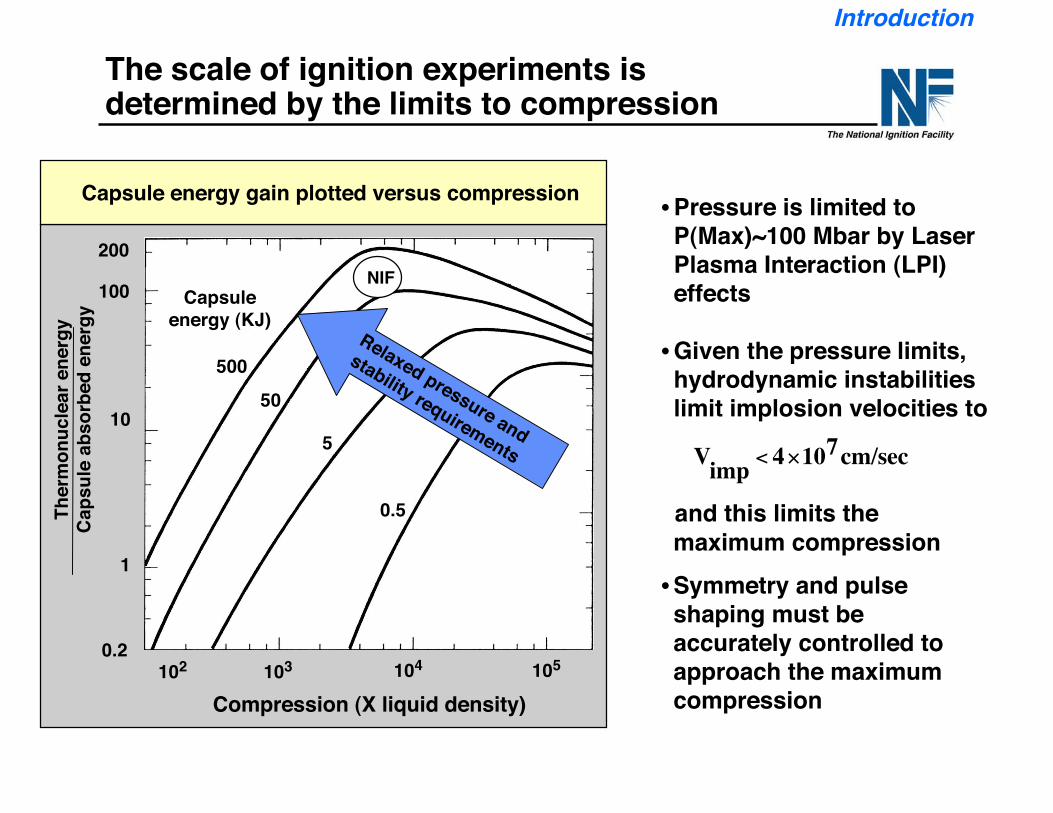
The scale of ignition experiments isdetermined by the limits to compression
200
100
10
1
0.2
Compression (X liquid density)102 103 104 105
50050
5
0.5
Capsuleenergy (KJ)
NIF
Relaxed pressure and
stability requirements
Ther
mon
ucle
ar e
nerg
yCa
psul
e ab
sorb
ed e
nerg
y
Capsule energy gain plotted versus compression •Pressure is limited toP(Max)~100 Mbar by LaserPlasma Interaction (LPI)effects
•Given the pressure limits,hydrodynamic instabilitieslimit implosion velocities to
!
Vimp
< 4"107cm/sec
and this limits themaximum compression•Symmetry and pulseshaping must beaccurately controlled toapproach the maximumcompression
Introduction
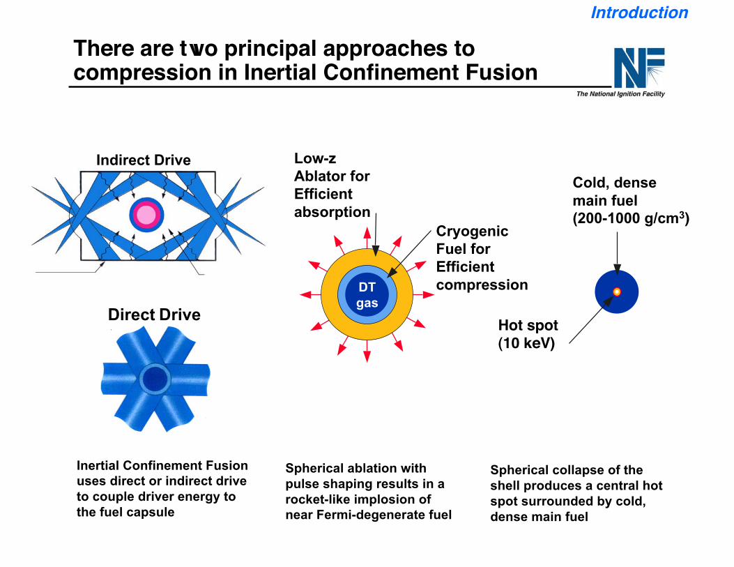
There are two principal approaches tocompression in Inertial Confinement Fusion
Inertial Confinement Fusionuses direct or indirect driveto couple driver energy tothe fuel capsule
Spherical ablation withpulse shaping results in arocket-like implosion ofnear Fermi-degenerate fuel
Spherical collapse of theshell produces a central hotspot surrounded by cold,dense main fuel
Direct Drive Hot spot(10 keV)
Cold, densemain fuel(200-1000 g/cm3)
Indirect Drive Low-zAblator forEfficientabsorption
CryogenicFuel for EfficientcompressionDT
gas
Introduction
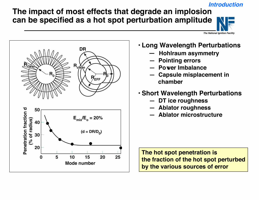
The impact of most effects that degrade an implosioncan be specified as a hot spot perturbation amplitude
• Long Wavelength Perturbations — Hohlraum asymmetry — Pointing errors — Power Imbalance — Capsule misplacement in
chamber
• Short Wavelength Perturbations — DT ice roughness — Ablator roughness — Ablator microstructure
The hot spot penetration isthe fraction of the hot spot perturbedby the various sources of error
Introduction
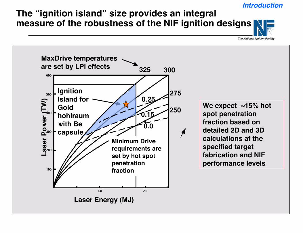
IntroductionThe “ignition island” size provides an integralmeasure of the robustness of the NIF ignition designs
IgnitionIsland forGoldhohlraumwith Becapsule
Minimum Driverequirements areset by hot spotpenetrationfraction
MaxDrive temperaturesare set by LPI effects
0.00.15
0.25
Laser Energy (MJ)
325 300
275
250
Lase
r Pow
er (T
W)
We expect ~15% hotspot penetrationfraction based ondetailed 2D and 3Dcalculations at thespecified targetfabrication and NIFperformance levels
NIF-0202-0XXXXppt15/GHM/tr
Outline
• Ignition Introduction
• Ignition program progress on hohlraums and capsules for ignitionexperiments.
— Hohlraums— Capsules
• Plan for experiments leading to first ignition target shots in 2010
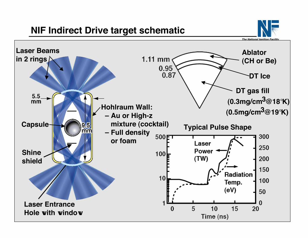
Typical Pulse Shape
Ablator(CH or Be)
DT Ice
DT gas fill
!
(0.3mg/cm3@18°K)
!
(0.5mg/cm3@19°K)Hohlraum Wall: – Au or High-z mixture (cocktail) – Full density or foam
Capsule
Laser Beamsin 2 rings
Laser EntranceHole with window
Shineshield
NIF Indirect Drive target schematic
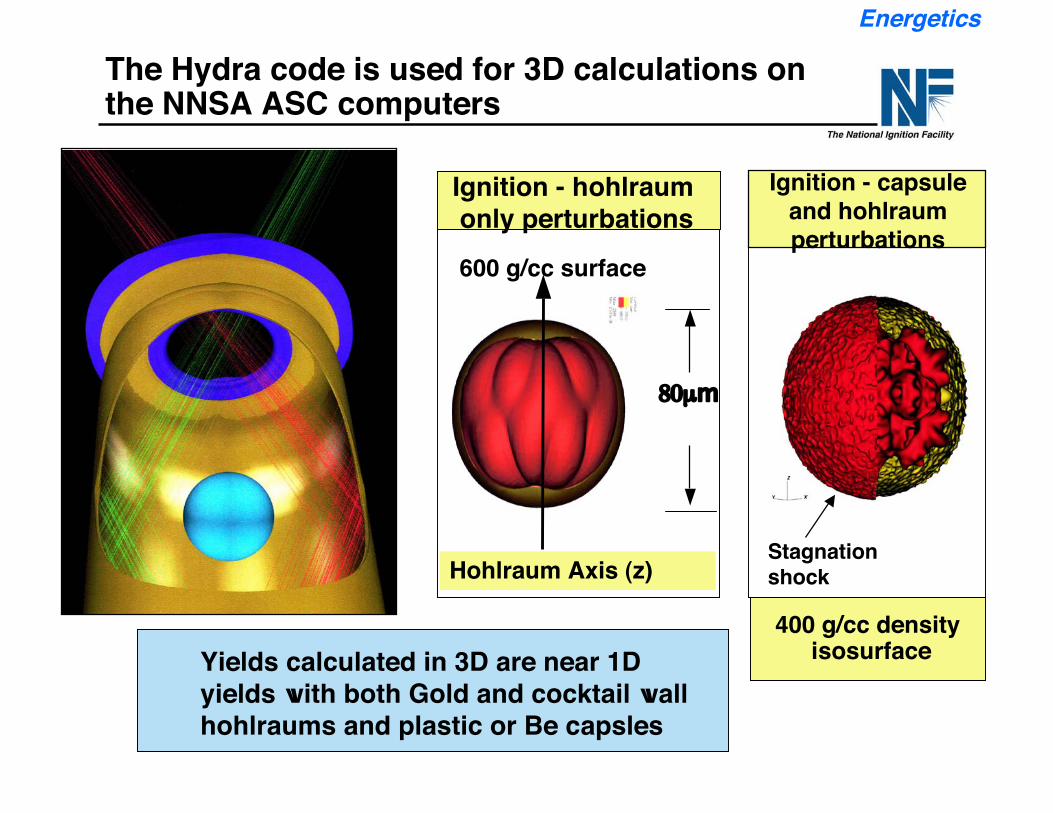
400 g/cc density isosurface
The Hydra code is used for 3D calculations onthe NNSA ASC computers
Energetics
(White circleat 40 microns)
Ignition - hohlraum only perturbations
Hohlraum Axis (z)
80µm
600 g/cc surface
Ignition - capsuleand hohlraumperturbations
Stagnationshock
Yields calculated in 3D are near 1Dyields with both Gold and cocktail wallhohlraums and plastic or Be capsles
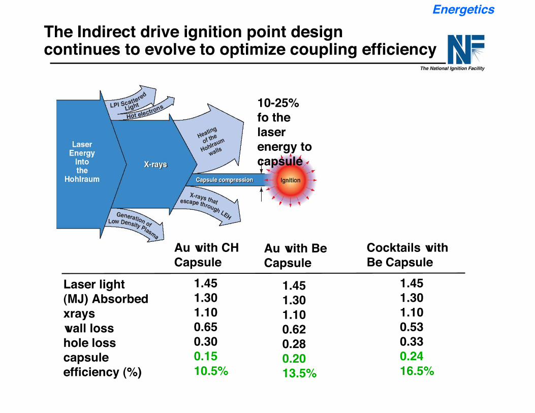
Energetics
10-25%fo thelaserenergy tocapsule
The Indirect drive ignition point designcontinues to evolve to optimize coupling efficiency
1.451.301.100.530.330.2416.5%
1.451.301.100.620.280.2013.5%
Laser light(MJ) Absorbedxrayswall losshole losscapsuleefficiency (%)
1.451.301.100.650.300.1510.5%
Au with CHCapsule
Au with BeCapsule
Cocktails withBe Capsule
NIF-0202-0XXXXppt15/GHM/tr
Outline
• Ignition Introduction
• Ignition program progress on hohlraums and capsules for ignitionexperiments.
— Hohlraums— Capsules
• Plan for experiments leading to first ignition target shots in 2010
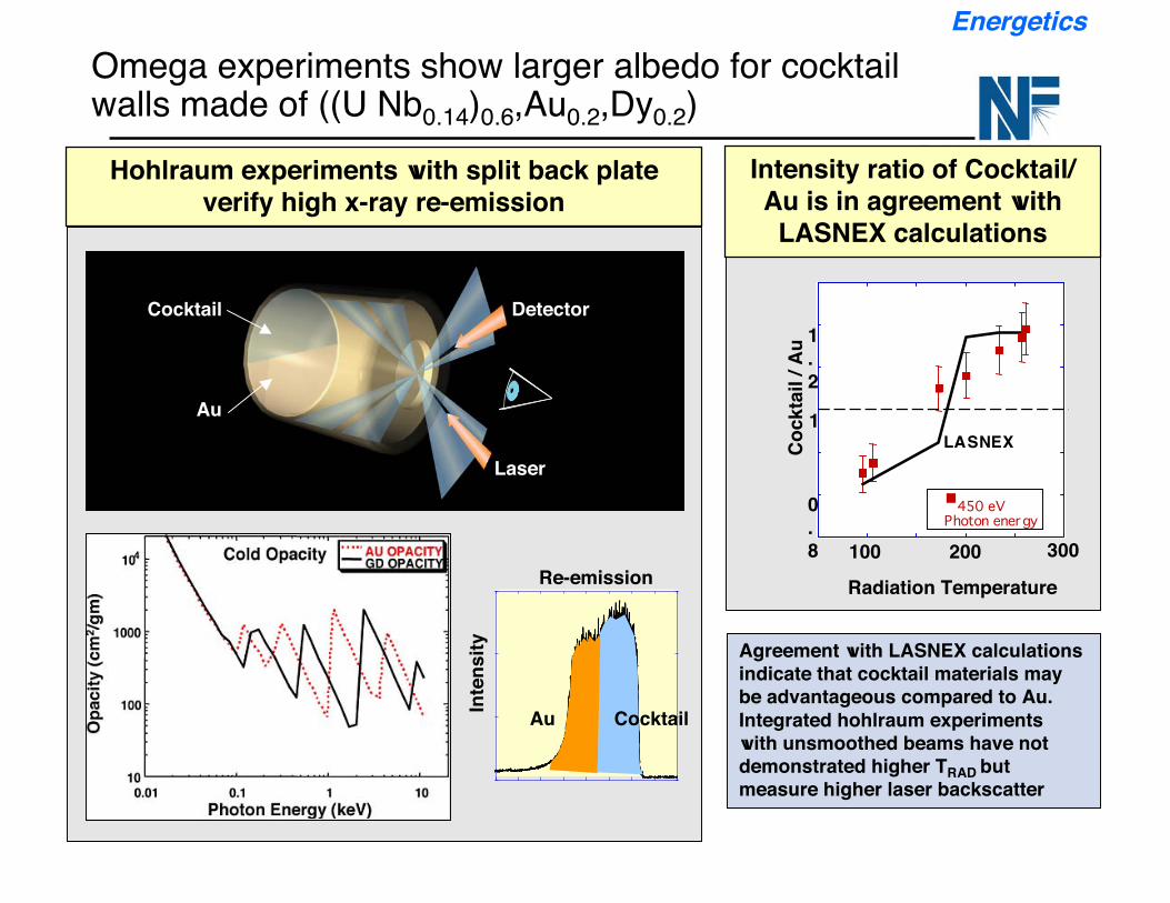
Omega experiments show larger albedo for cocktailwalls made of ((U Nb0.14)0.6,Au0.2,Dy0.2)
Agreement with LASNEX calculationsindicate that cocktail materials maybe advantageous compared to Au.Integrated hohlraum experimentswith unsmoothed beams have notdemonstrated higher TRAD butmeasure higher laser backscatter
Energetics
Hohlraum experiments with split back plateverify high x-ray re-emission
Intensity ratio of Cocktail/Au is in agreement with
LASNEX calculations
Cocktail
Re-emission
Inte
nsity
Au
1
0.8
1.2
Radiation Temperature
Cock
tail
/ Au
100 200 300
LASNEX
450 eVPhoton energy
Detector
Laser
Cocktail
Au
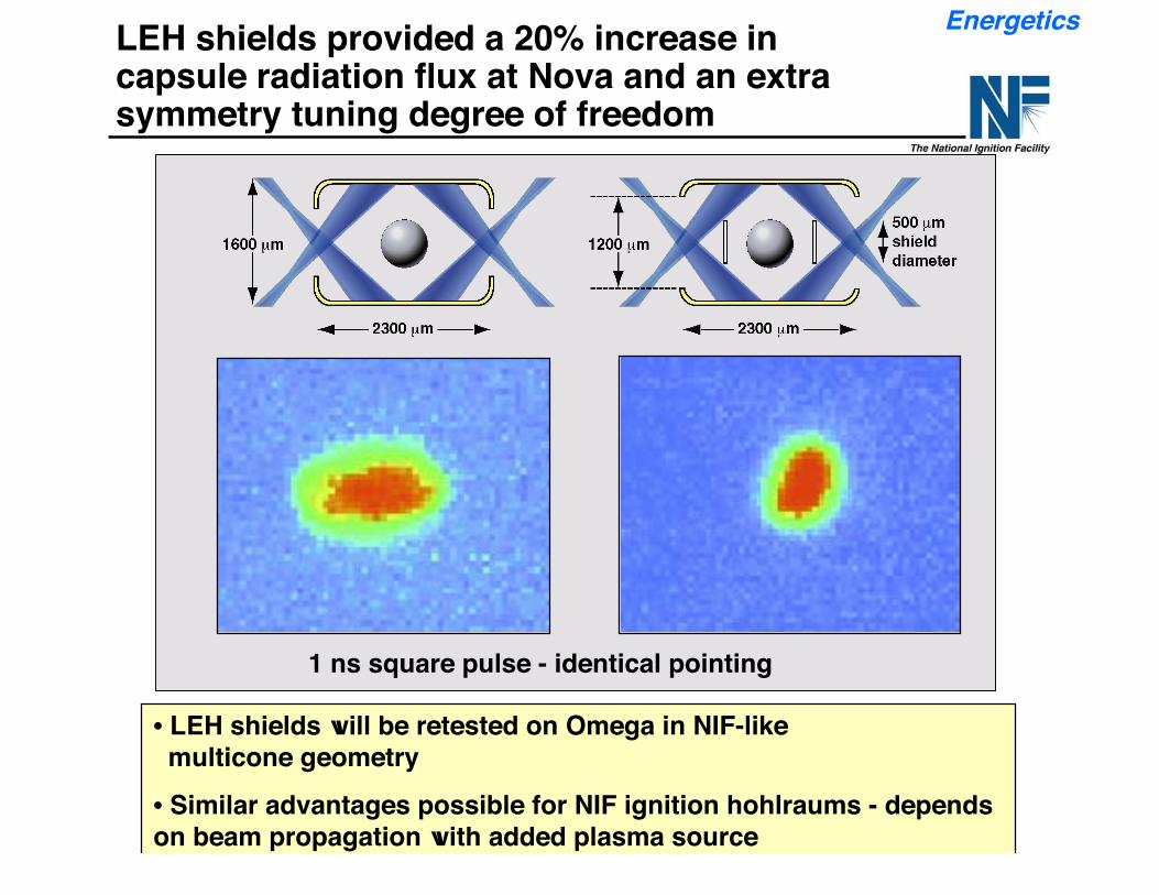
• LEH shields will be retested on Omega in NIF-like multicone geometry• Similar advantages possible for NIF ignition hohlraums - dependson beam propagation with added plasma source
1 ns square pulse - identical pointing
LEH shields provided a 20% increase incapsule radiation flux at Nova and an extrasymmetry tuning degree of freedom
Energetics
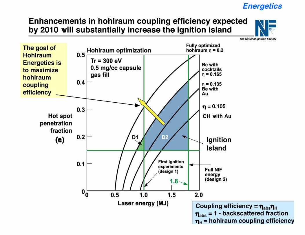
Enhancements in hohlraum coupling efficiency expectedby 2010 will substantially increase the ignition island
Energetics
Coupling efficiency = ηabsηHηabs = 1 - backscattered fractionηH = hohlraum coupling efficiency
The goal ofHohlraumEnergetics isto maximizehohlraumcouplingefficiency
IgnitionIsland
(e)
η = 0.105
CH with Au
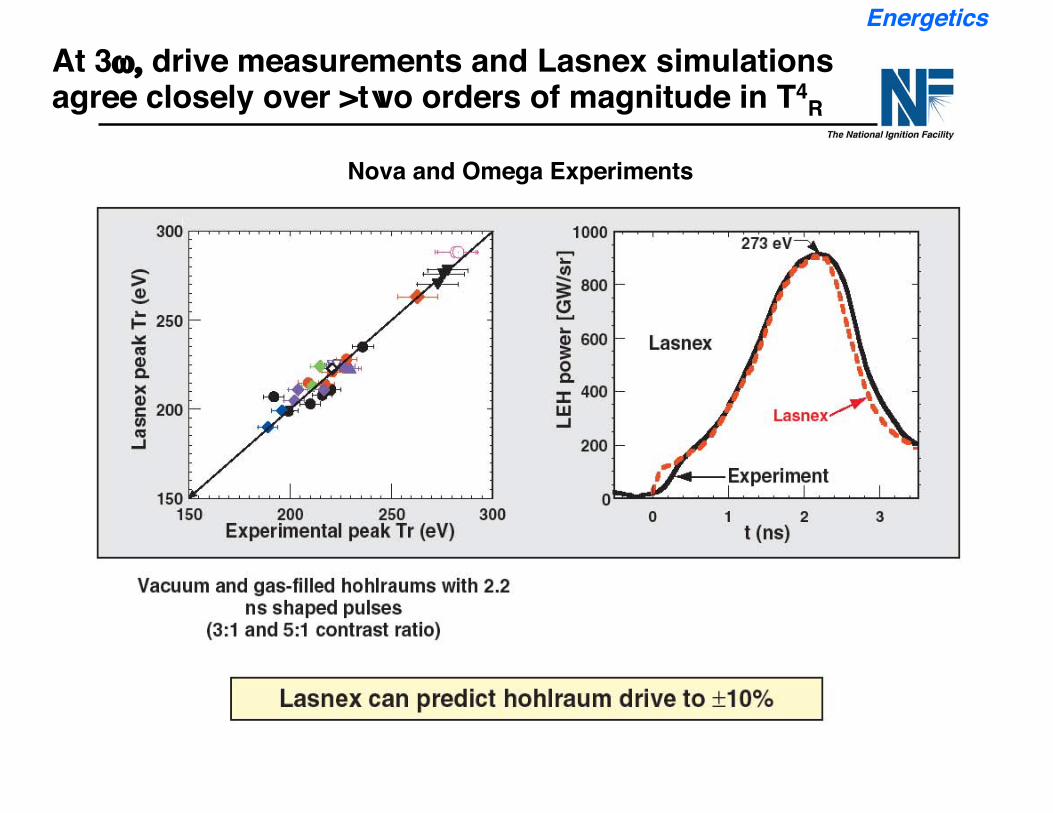
At 3ω, drive measurements and Lasnex simulationsagree closely over >two orders of magnitude in T4
R
Nova and Omega Experiments
Energetics
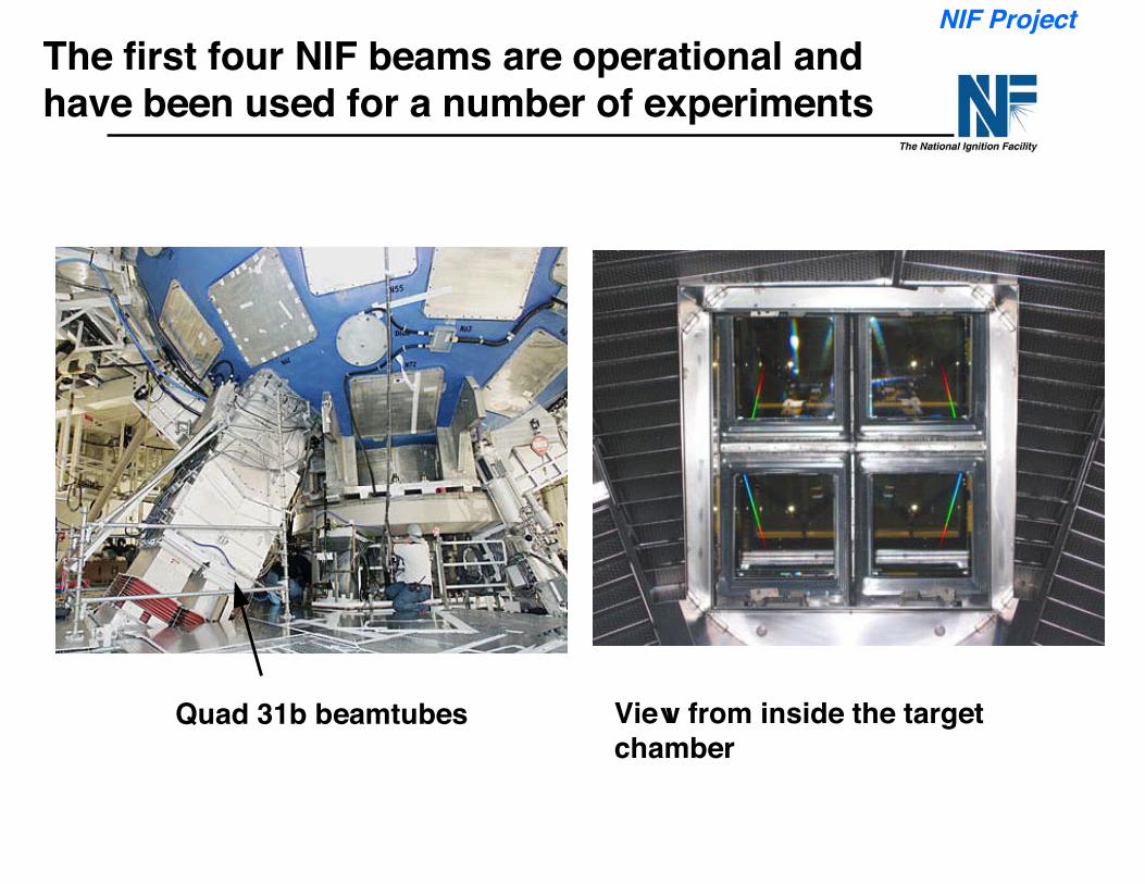
The first four NIF beams are operational andhave been used for a number of experiments
View from inside the targetchamber
Quad 31b beamtubes
NIF Project
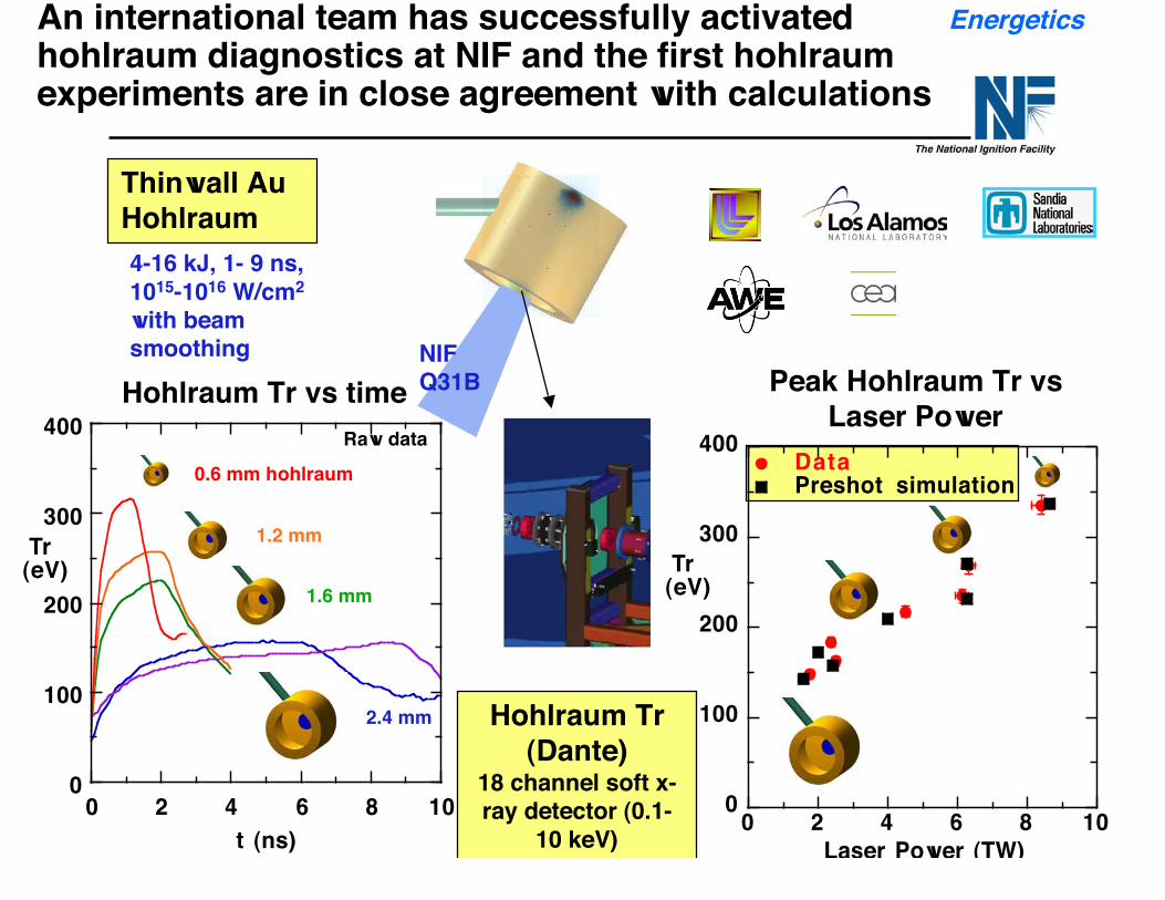
An international team has successfully activatedhohlraum diagnostics at NIF and the first hohlraumexperiments are in close agreement with calculations
Thinwall AuHohlraum4-16 kJ, 1- 9 ns,1015-1016 W/cm2
with beamsmoothing NIF
Q31B
0
100
200
300
400
0 2 4 6 8 10
Tr (eV)
t (ns)
1.2 mm
2.4 mm
1.6 mm
0.6 mm hohlraum
Hohlraum Tr vs timeRaw data
Peak Hohlraum Tr vsLaser Power
0
100
200
300
400
0 2 4 6 8 10
DataPreshot simulation
Tr (eV)
Laser Power (TW)
Hohlraum Tr(Dante)
18 channel soft x-ray detector (0.1-
10 keV)
Energetics
NIF-0202-0XXXXppt15/GHM/tr
Outline
• Ignition Introduction
• Ignition program progress on hohlraums and capsules for ignitionexperiments.
— Hohlraums— Capsules
• Plan for experiments leading to first ignition target shots in 2010
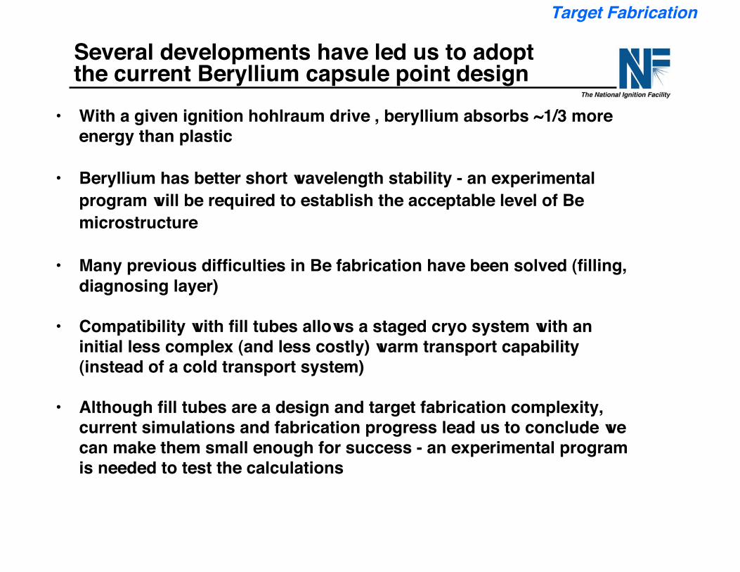
Several developments have led us to adoptthe current Beryllium capsule point design
• With a given ignition hohlraum drive , beryllium absorbs ~1/3 moreenergy than plastic
• Beryllium has better short wavelength stability - an experimentalprogram will be required to establish the acceptable level of Bemicrostructure
• Many previous difficulties in Be fabrication have been solved (filling,diagnosing layer)
• Compatibility with fill tubes allows a staged cryo system with aninitial less complex (and less costly) warm transport capability(instead of a cold transport system)
• Although fill tubes are a design and target fabrication complexity,current simulations and fabrication progress lead us to conclude wecan make them small enough for success - an experimental programis needed to test the calculations
Target Fabrication
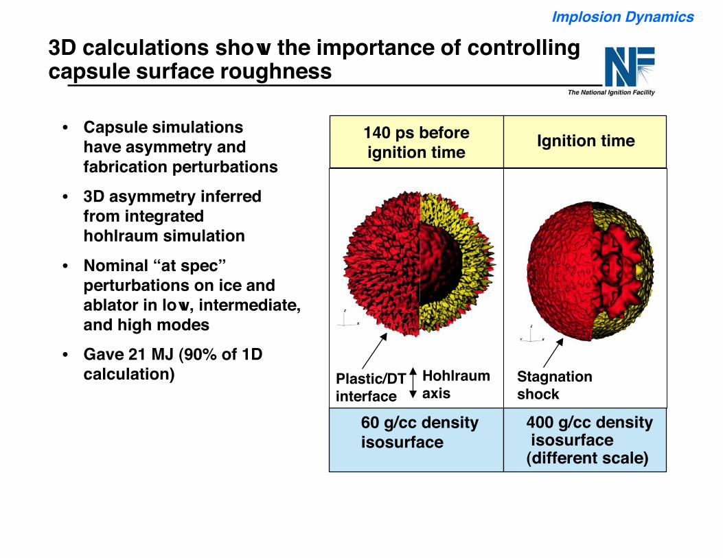
3D calculations show the importance of controllingcapsule surface roughness
• Capsule simulations have asymmetry and fabrication perturbations
• 3D asymmetry inferredfrom integratedhohlraum simulation
• Nominal “at spec”perturbations on ice andablator in low, intermediate,and high modes
• Gave 21 MJ (90% of 1Dcalculation)
140 ps beforeignition time
Plastic/DTinterface
Hohlraumaxis
60 g/cc density isosurface
Ignition time
Stagnationshock
400 g/cc density isosurface (different scale)
Implosion Dynamics
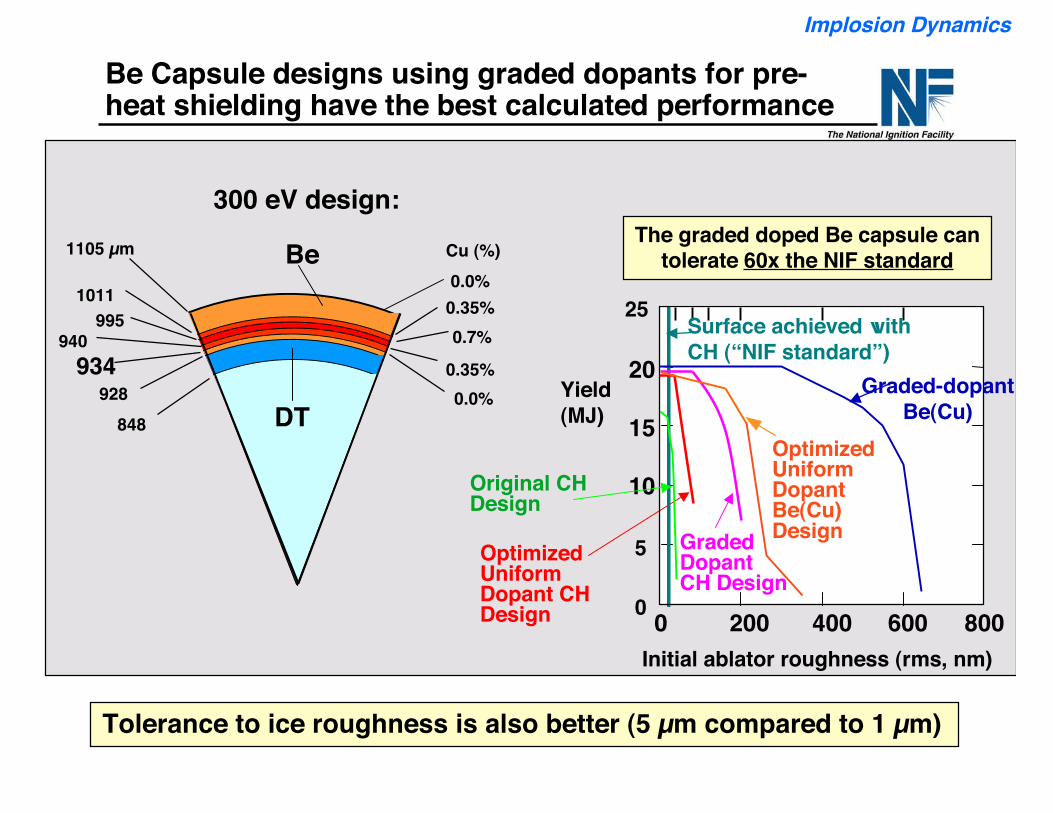
0.35%
0.7%
848928
1105 µm
934940
9951011
0.0%
Cu (%)
300 eV design:
Be
DT
0.0%0.35%
200Initial ablator roughness (rms, nm)
0
5
10
15
20
25
Yield(MJ)
OptimizedUniformDopant CHDesign
Surface achieved withCH (“NIF standard”)
400 600 8000
Graded-dopantBe(Cu)
Original CHDesign
GradedDopantCH Design
The graded doped Be capsule cantolerate 60x the NIF standard
Be Capsule designs using graded dopants for pre-heat shielding have the best calculated performance
Tolerance to ice roughness is also better (5 µm compared to 1 µm)
Implosion Dynamics
OptimizedUniformDopantBe(Cu)Design
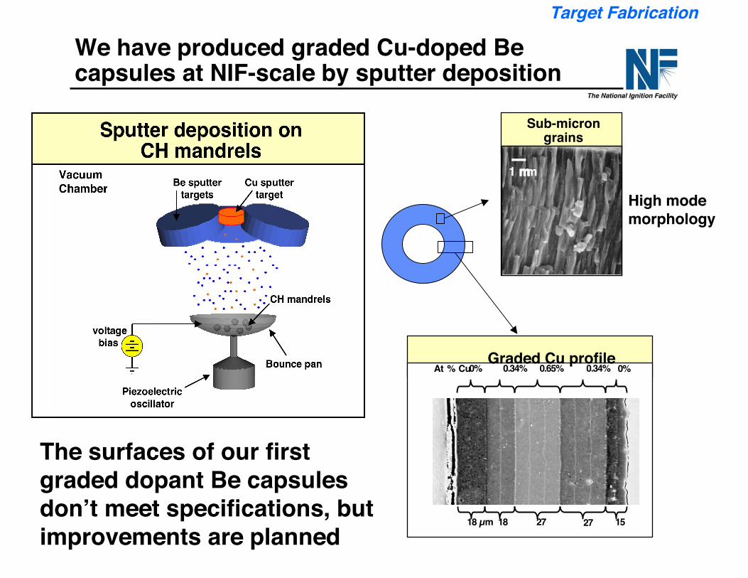
High modemorphology
Graded Cu profile
18 µm 18 27 27 15
0.34% 0.65% 0.34% 0% 0% At % Cu
Sub-microngrains
1 mm
We have produced graded Cu-doped Becapsules at NIF-scale by sputter deposition
The surfaces of our firstgraded dopant Be capsulesdon’t meet specifications, butimprovements are planned
Target Fabrication
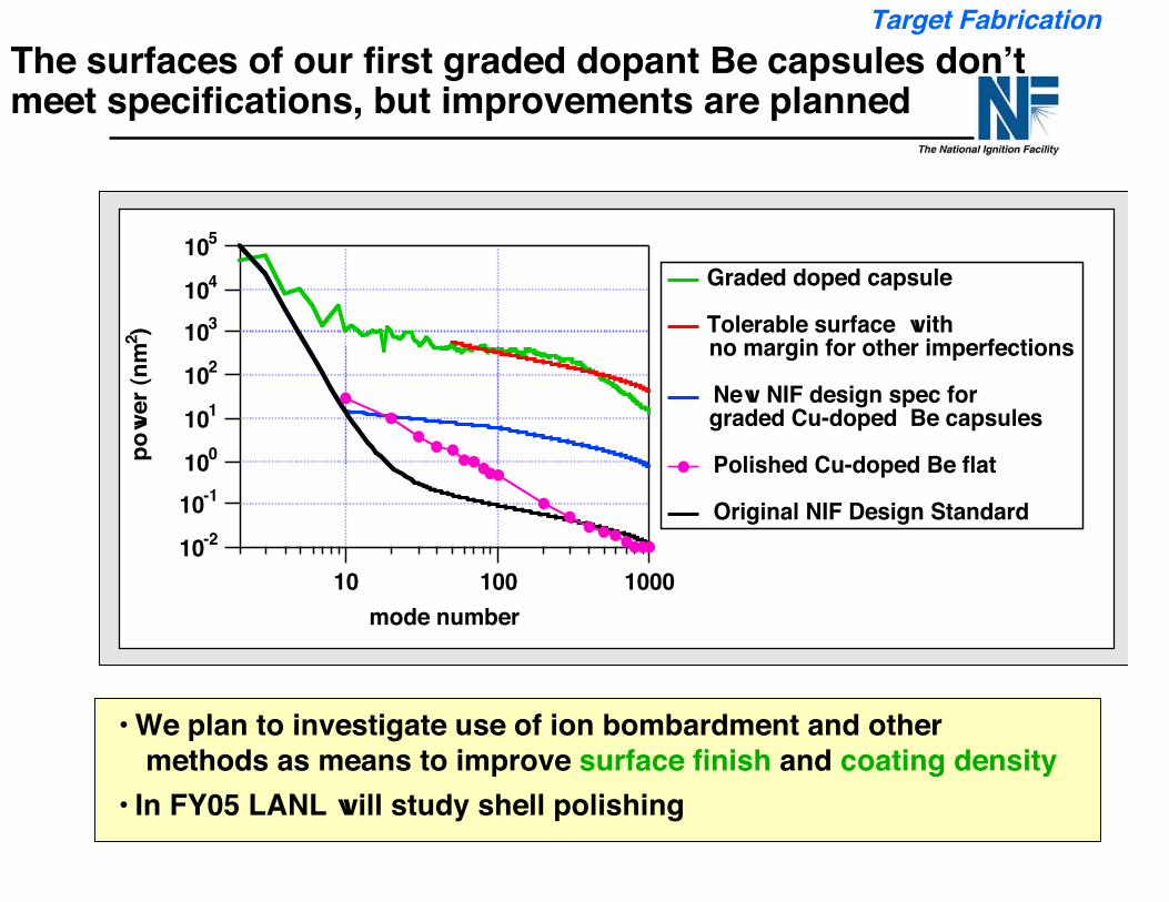
• We plan to investigate use of ion bombardment and othermethods as means to improve surface finish and coating density
• In FY05 LANL will study shell polishing
10-2
10-1
100
101
102
103
104
105
po
we
r (n
m2)
10 100 1000
mode number
Graded doped capsule
Tolerable surface with no margin for other imperfections
New NIF design spec for graded Cu-doped Be capsules
Polished Cu-doped Be flat
Original NIF Design Standard
The surfaces of our first graded dopant Be capsules don’tmeet specifications, but improvements are planned
Target Fabrication
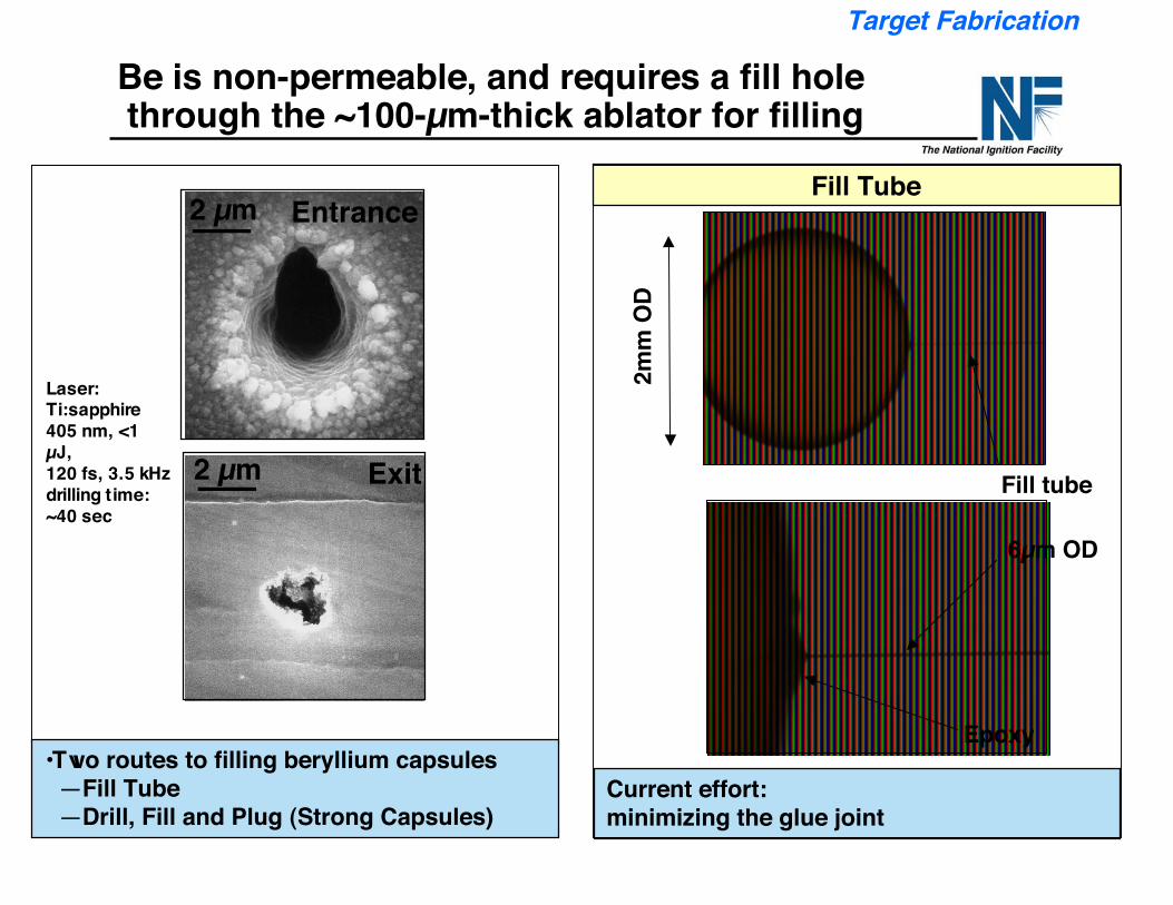
•Two routes to filling beryllium capsules—Fill Tube—Drill, Fill and Plug (Strong Capsules)
2 µm Entrance
Exit2 µm
Laser:Ti:sapphire405 nm, <1µJ,120 fs, 3.5 kHzdrilling time:~40 sec
Fill tube
Epoxy
6µm OD
2mm
OD
Fill Tube
Current effort:minimizing the glue joint
Target Fabrication
Be is non-permeable, and requires a fill hole through the ~100-µm-thick ablator for filling
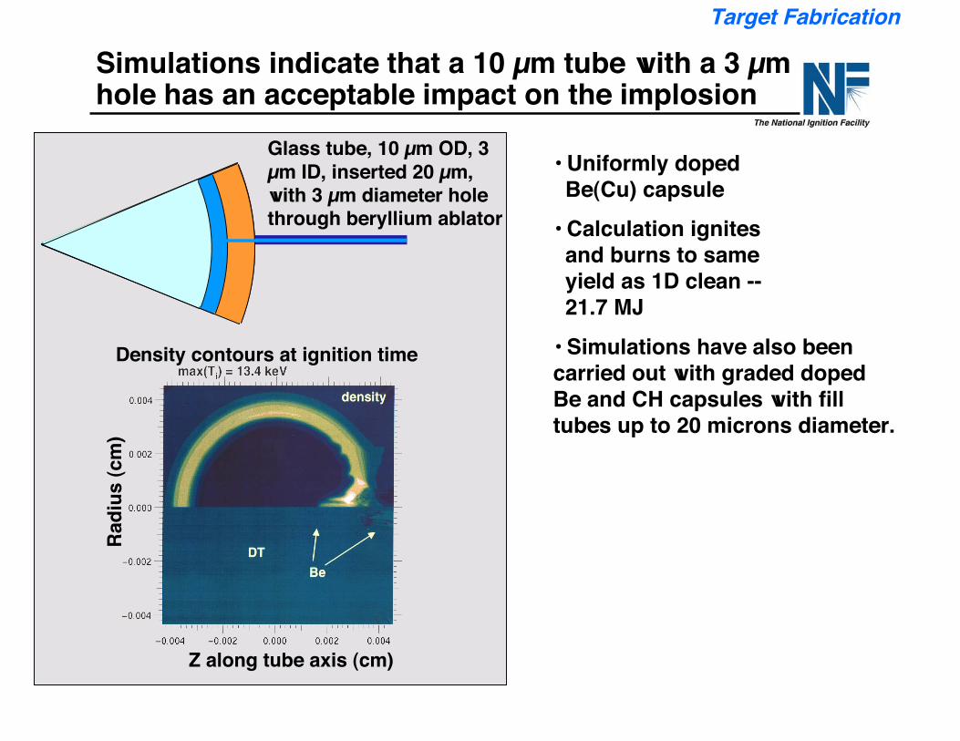
Glass tube, 10 µm OD, 3µm ID, inserted 20 µm,with 3 µm diameter holethrough beryllium ablator
Density contours at ignition time
Z along tube axis (cm)
Radi
us (c
m)
Simulations indicate that a 10 µm tube with a 3 µmhole has an acceptable impact on the implosion
• Uniformly doped Be(Cu) capsule• Calculation ignites and burns to same yield as 1D clean -- 21.7 MJ• Simulations have also beencarried out with graded dopedBe and CH capsules with filltubes up to 20 microns diameter.
Target Fabrication
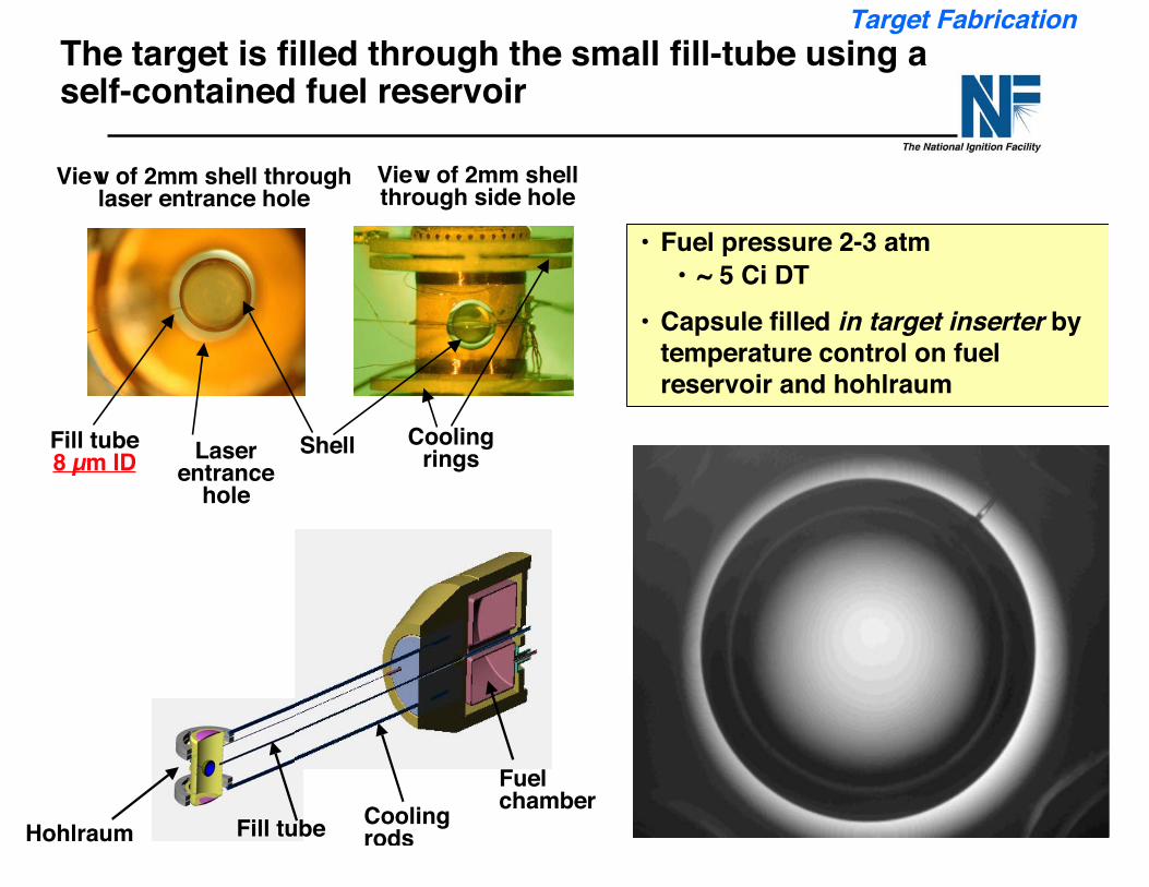
The target is filled through the small fill-tube using aself-contained fuel reservoir
View of 2mm shell throughlaser entrance hole
View of 2mm shellthrough side hole
ShellLaserentrance
hole
Coolingrings
Fill tube8 µm ID
Hohlraum Fill tube Coolingrods
Fuelchamber
• Fuel pressure 2-3 atm• ~ 5 Ci DT
• Capsule filled in target inserter bytemperature control on fuelreservoir and hohlraum
Target Fabrication
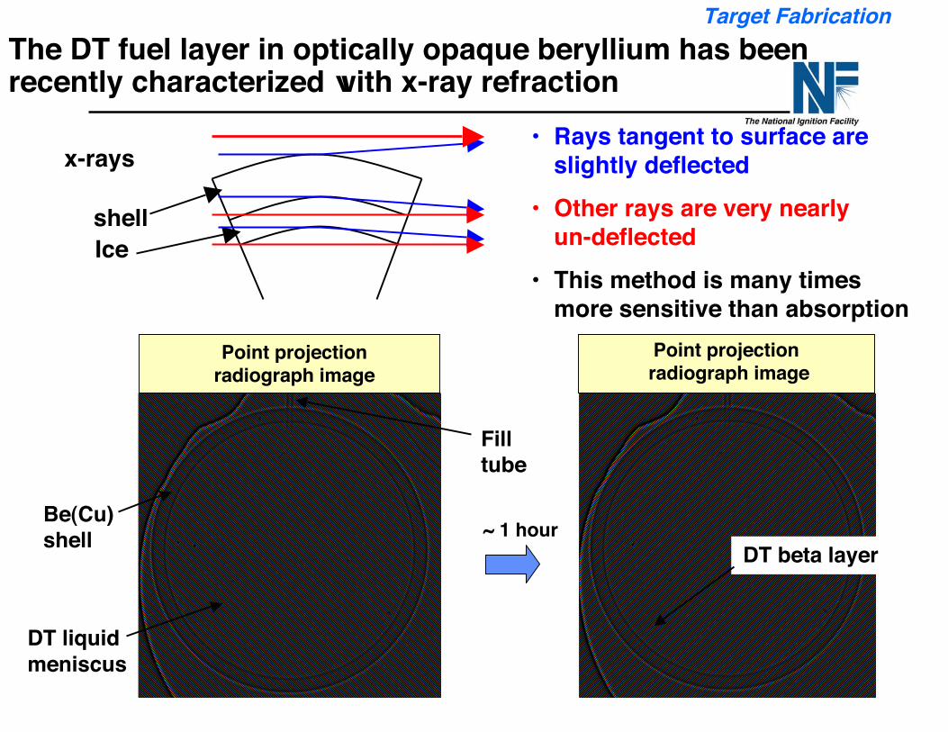
The DT fuel layer in optically opaque beryllium has beenrecently characterized with x-ray refraction
Point projectionradiograph image
DT liquidmeniscus
Be(Cu)shell
Filltube
~ 1 hour
Point projection radiograph image
DT beta layer
Ice
• Rays tangent to surface areslightly deflected
• Other rays are very nearly un-deflected
• This method is many timesmore sensitive than absorption
x-rays
shell
Target Fabrication
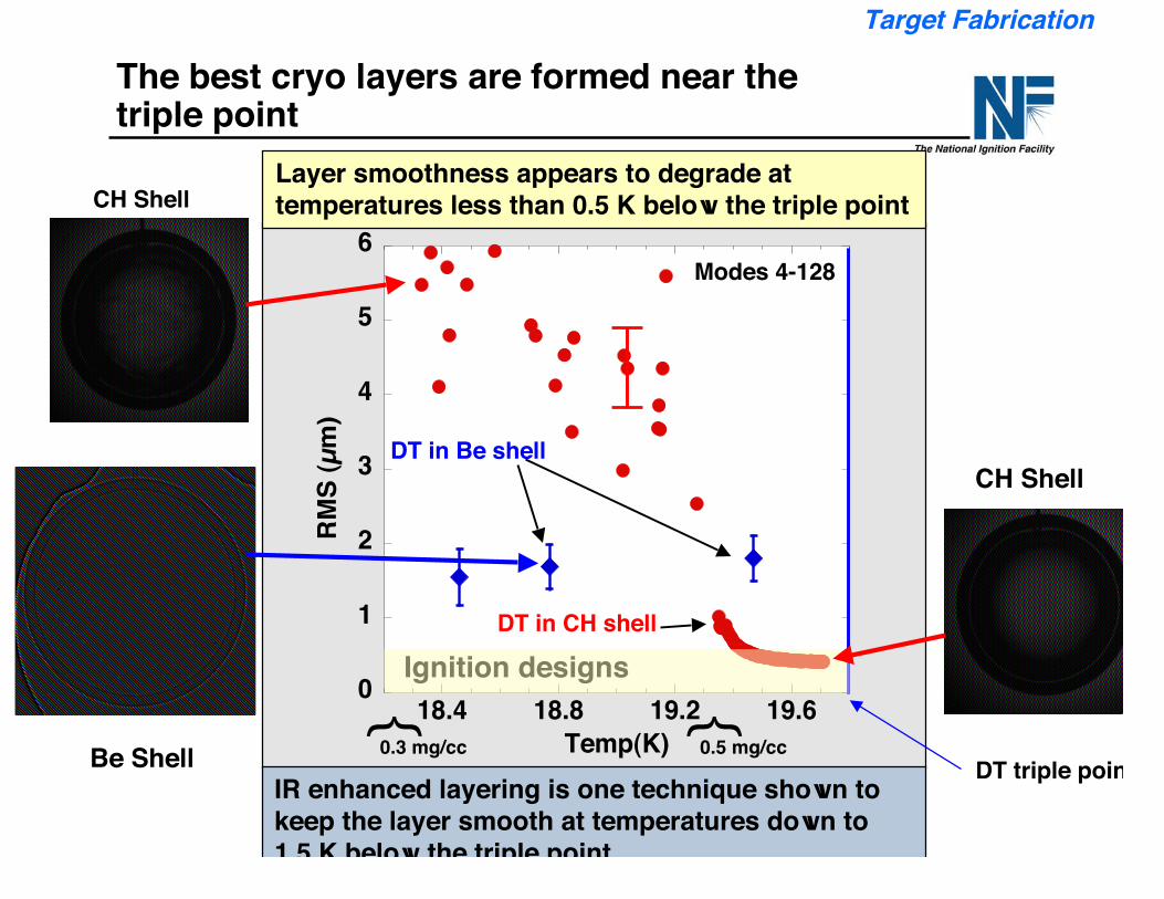
The best cryo layers are formed near thetriple point
0
1
2
3
4
5
6
18.4 18.8 19.2 19.6
RM
S (
µm
)
Temp(K)DT triple point
IR enhanced layering is one technique shown tokeep the layer smooth at temperatures down to1.5 K below the triple point
Layer smoothness appears to degrade attemperatures less than 0.5 K below the triple point
DT in Be shell
DT in CH shell
Modes 4-128
Ignition designs
0.5 mg/cc}
0.3 mg/cc
}
Target Fabrication
CH Shell
CH Shell
Be Shell
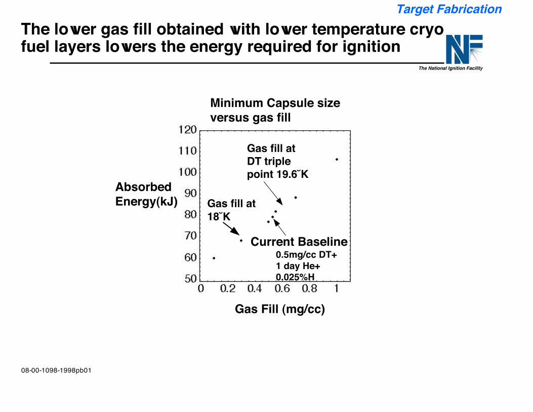
The lower gas fill obtained with lower temperature cryofuel layers lowers the energy required for ignition
Target Fabrication
08-00-1098-1998pb01
Haan 2-4
Absorbed Energy(kJ)
Gas Fill (mg/cc)
0.5mg/cc DT+1 day He+0.025%H
Gas fill atDT triplepoint 19.6˘K
Minimum Capsule sizeversus gas fill
Current Baseline
Gas fill at18˘K
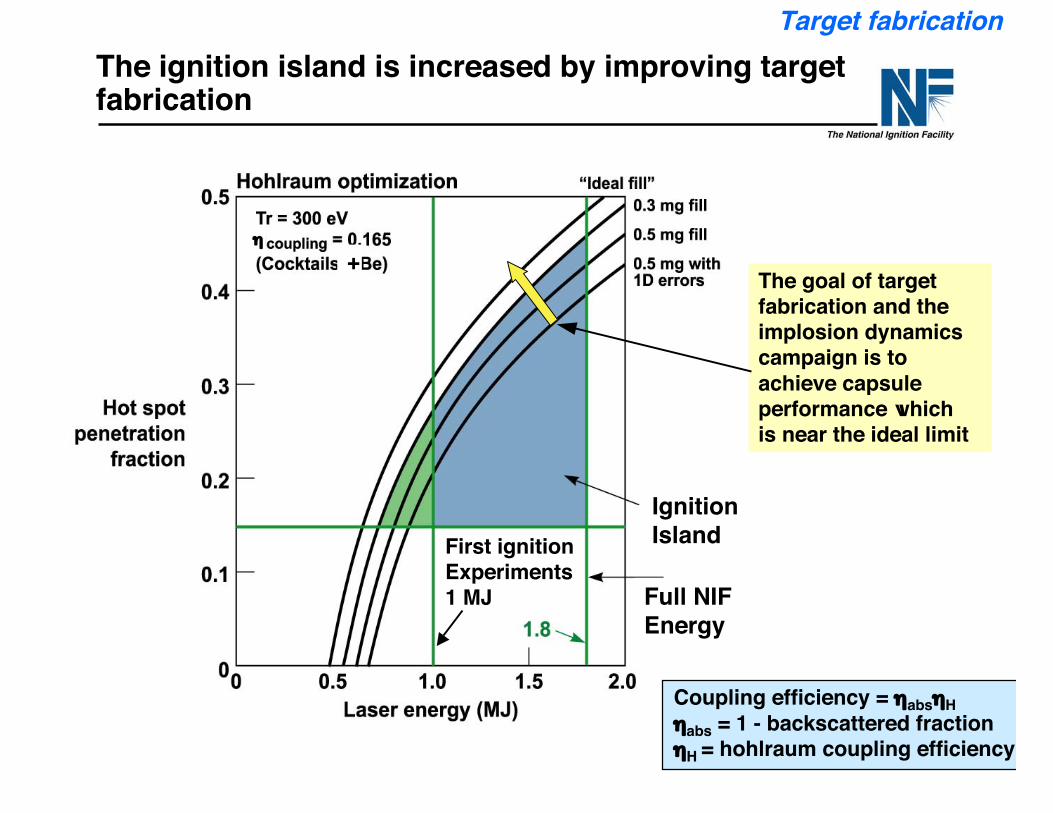
The ignition island is increased by improving targetfabrication
Target fabrication
Coupling efficiency = ηabsηHηabs = 1 - backscattered fractionηH = hohlraum coupling efficiency
The goal of targetfabrication and theimplosion dynamicscampaign is toachieve capsuleperformance whichis near the ideal limit
First ignitionExperiments1 MJ
IgnitionIsland
+η
Full NIFEnergy
NIF-0202-0XXXXppt15/GHM/tr
Outline
• Ignition Introduction
• Ignition program progress on hohlraums and capsules for ignitionexperiments.
— Hohlraums— Capsules
• Plan for experiments leading to first ignition target shots in 2010
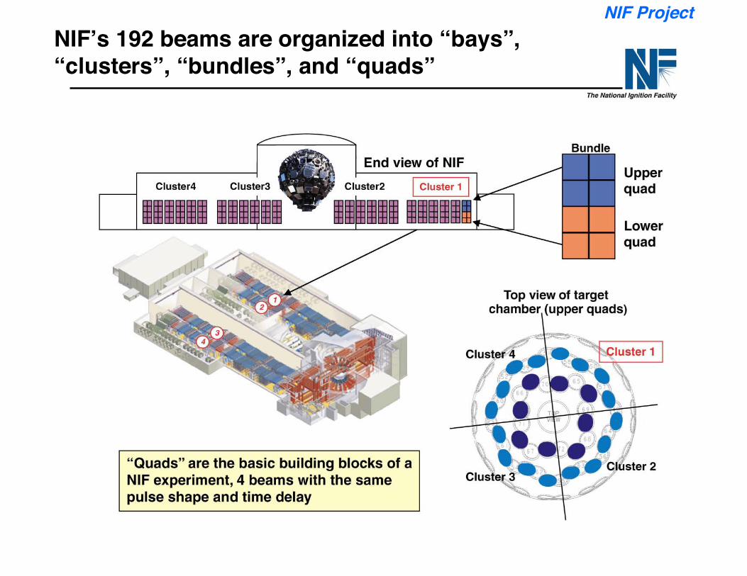
NIF’s 192 beams are organized into “bays”,“clusters”, “bundles”, and “quads”
NIF Project
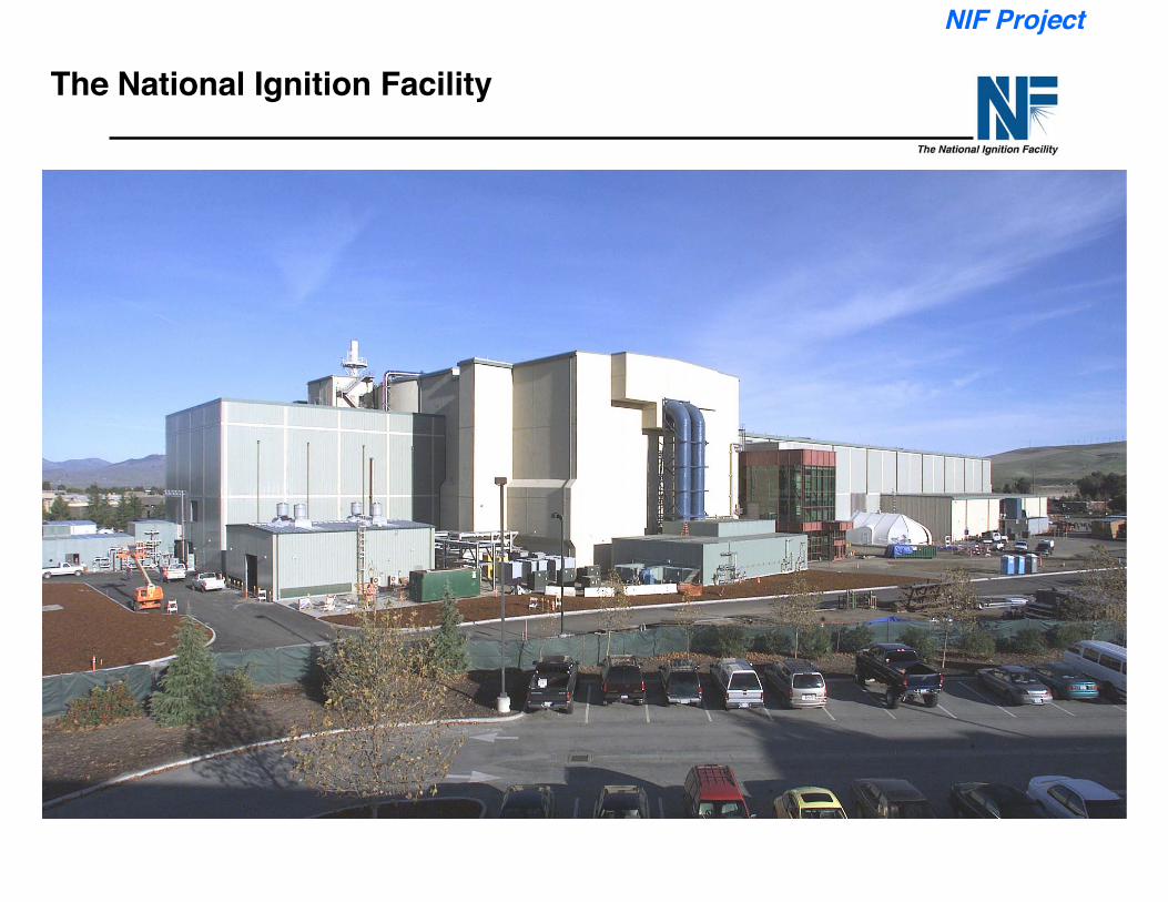
The National Ignition Facility
NIF Project
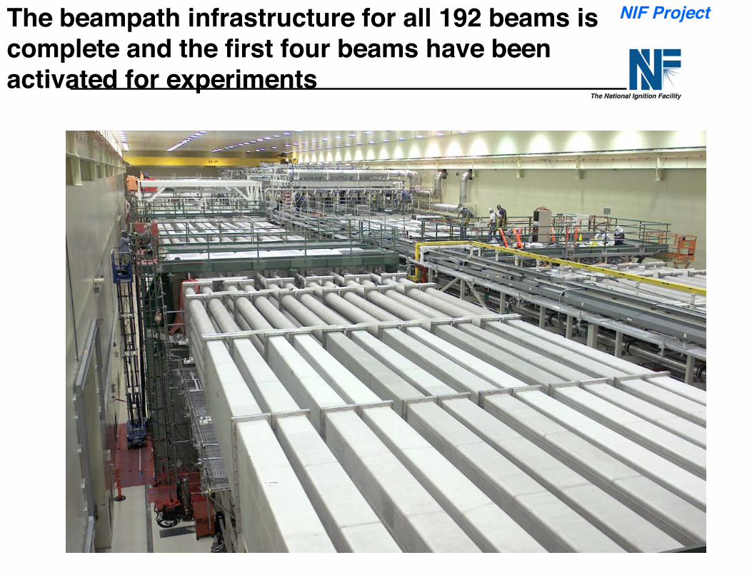
The beampath infrastructure for all 192 beams iscomplete and the first four beams have beenactivated for experiments
NIF Project
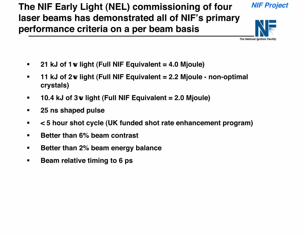
The NIF Early Light (NEL) commissioning of fourlaser beams has demonstrated all of NIF’s primaryperformance criteria on a per beam basis
21 kJ of 1w light (Full NIF Equivalent = 4.0 Mjoule) 11 kJ of 2w light (Full NIF Equivalent = 2.2 Mjoule - non-optimal
crystals) 10.4 kJ of 3w light (Full NIF Equivalent = 2.0 Mjoule) 25 ns shaped pulse < 5 hour shot cycle (UK funded shot rate enhancement program) Better than 6% beam contrast Better than 2% beam energy balance Beam relative timing to 6 ps
NIF Project
Firstcluster
Firstbundles
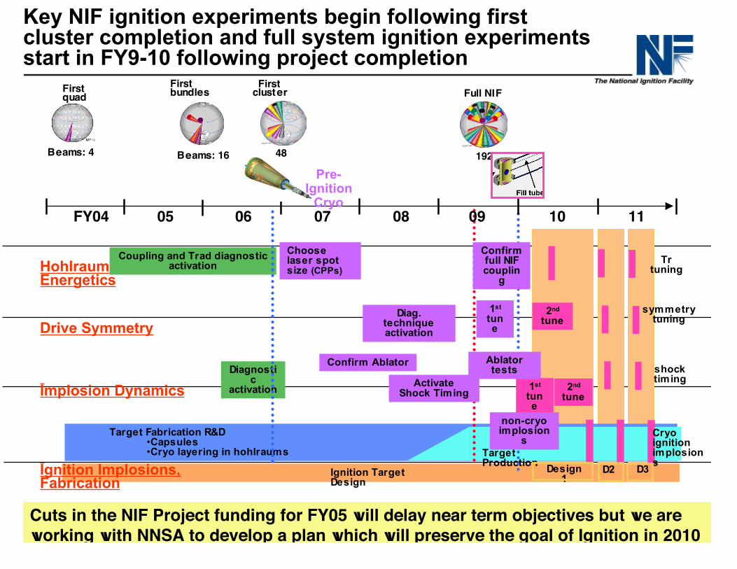
Key NIF ignition experiments begin following firstcluster completion and full system ignition experimentsstart in FY9-10 following project completion
Target Fabrication R&D•Capsules•Cryo layering in hohlraums
Diagnostic
activation
Confirm Ablator
Beams: 4
Drive Symmetry
Implosion Dynamics
0907FY04 05 06 08
Coupling and Trad diagnosticactivationHohlraum
Energetics
Firstquad
ActivateShock Timing
Chooselaser spotsize (CPPs)
Pre-Ignition
Cryo
1st
tune
48
Diag.techniqueactivation
Ignition TargetDesign
Ignition Implosions,Fabrication
TargetProduction
Beams: 16
10 11
2nd
tune
2nd
tune
symmetrytuning
shocktiming
1st
tune
Trtuning
Design1
D2 D3
Cryoignitionimplosions
non-cryoimplosion
s
Full NIF
192
Confirmfull NIFcouplin
g
Ablatortests
Cuts in the NIF Project funding for FY05 will delay near term objectives but we areworking with NNSA to develop a plan which will preserve the goal of Ignition in 2010
Summary/Conclusions
• Be targets are ~1/3 more efficient than earlier CH designs and morerobust to hydrodynamic instability.
• Major advances in Be capsules filled through a few micron fill tubehave opened up the possibility of implementing a greatly simplifiedcryo target support system on NIF for early ignition experiments
• Success with Be capsules, and the use of “cocktail” wall hohlraumswould result in a target which is about 2/3 more efficient than theoriginal baseline targets.
• This would enable successful ignition experiments at ~1 MJ in the firstcouple of years after completion of the NIF and allow much higheryields when NIF operates at its full design energy of 1.8 MJ.
• Additional optimization and hohlraum features such as laser entrancehole shine shields can yield further increases in coupling efficiencyand yields.