The National Ignition Facility (NIF) Wavefront Control System
UCRL-ID-130999
National Ignition Facility (NIF) Operations Procedures Plan
D Mantrom K Collins G. Hermes
May 6,199s
This is an informal report intended primarily forinternal or limited external distribution The opinions and conclusions stated are those of the author and may 01 may not be those of the Laboratory Work performed under the auspices ofthe US Depxtment of Energy by the LawrenceLivermoreNational Laboratory under Contract W-7405.ENG-48

DISCLAIMER
This document was prepared as an account of work spasored by an agency of the United States Government Neither the United States Government nor the University of California nor any of their employees, makes any warranty, express or implied, or assumes any legal liability or responsibility for the accuracy, completeness, or usefulness of any information, appara$s, product, or process disclosed, or represents that its we would not infringe privately owned rights Reference herein to any specific commercial product, process, or service by trade name, trademark, manufacturer, or &h-wise, does not necessarily constitute or imply its endorsement, recommendation, or favoring by the United States Govamnent or the University of California The views and opinions of authors expressed herein do not necessarily state or retled those of the United States Gov-ent or the University of California, and shall not be used for advertising or product endorsement pwposw
This repart has been reproduced directly ham the best available copy
Available to DOE and DOE contractors from the Office of Scientific and Technical Information
P 0 Box 62, Oak Ridge, TN 37831 Prices available t?om (615) 57H401, FTS 626-8401
Available to the public from the National Technical Information Service
US Department of Commerce 5285 Port Royal Rd ,
Springfield, VA 22161
r
I
NIF-0009004 (Revision 0)
NATIONAL IGNITION FACILITY (NIF)
OPERATIONS PROCEDURES PLAN
D. Mantrom , K. Collins, and G. Hermes
May 6, 1998
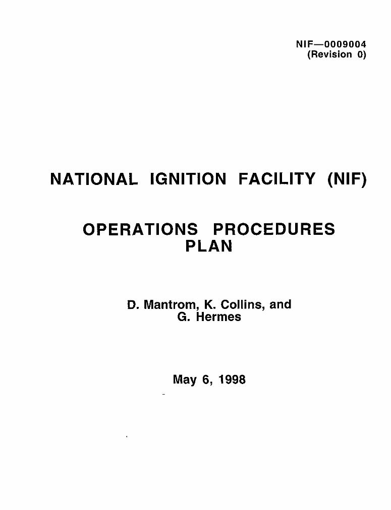
NATIONAL IGNITION FACILITY (NIF)
OPERATIONS PROCEDURES PLAN
(Revision 0)
Reviewed /concurred by
te Project Engineer for Start-up
Approved bc454 c&i Curtis Clower Associate Project Engineer for Start-up
Date
Page ii

r
PREFACE
The National Ignition Facility (NIF) is a US Department of Energy (DOE) experimental facility that will be used to study inertial confinement fusion (ICF) and other physical phenomena that occur at very high temperatures and pressures. It will use multiple, high-power, short-pulse laser beams that converge on a small target.
The NIF Startup and Operations Planning Group is responsible for providing the management and technical oversight necessary to ensure a smooth project transition from the construction and equipment development phase of NIF to integrated beam line operation in a fully functional facility. As part of this responsibility, this plan has been developed to address the development and implementation of NIF Operations procedures These procedures are important because it is anticipated that there will be 500 or more discrete technical/engineering tasks or activities involving not only complex equipment but also the safety of operations personnel.
Due to the large number of procedures required, timeliness is an important factor in developing NIF Operations procedures. In addition, all procedures must be in place prior to conducting Operational Readiness Reviews (ORR) which are required before actual NIF operations can begin
NIF Operations procedures include all procedures involving the operation, maintenance, assembly (recurring), and installation (recurring) of NIF facility systems as well as facility administration and training They do not include procedures for one-time facility construction or installation tasks nor do they include Acceptance Test Procedures (ATPs) or Operational Test Procedures (OTPs).
*This work was performed under the auspices of the U S DOE by Lawrence Livermore National Laboratory, Livermore California under Contract No W-740%Eng-48
Page iii

TABLE OF CONTENTS
PREFACE LISTOF FIGUREi’ : : ” : LISTOFTABLES. . . :’
t.. .
1 INTRODUCTION
1.1 Purpose of Plan... . . . . . . . . . . . . . . . . . . . . . . . . . . . . . . . . . . . . . . . . . . . . . . . . 12 Scope of Plan . . . . . . . . . . . . . . . . . . . . . . . . . . . . . . . . . . . . . . . . . . . . . . . . . . . . . . . . . . . . . . . . . . . 13 Philosophy of Plan . . . . . . . . . . . . . . . . . . . . . . . . . . . . . . . . . . . . . . . . . . . . . . . . . . . . . . . . . . . . . . . . . . . . .
2. DEVELOPING NIF OPERATIONS PROCEDURES . . . . . . . . . . . . . . . . . . . . . . . . . .
2.1 Introduction . . . . . . . . . . . . . . . . . . . . . . . . . . . . . . . . . . . . . . . . . . . . 2.2 Purpose of Operations Procedures . . . . . . . . . . . . . . . . . . . . . . . . . . . . . . . . 2.3 Procedure Organization . . . . . . . . . . . . . . . . . . . . . . . . . . . . . . . . . . . . . . . . . . . . . . . . . . . . . . . 2.4 Procedure Numbering Scheme. . . . . . . . . . . . . . . . . . . . . . . . . . . . . . . . . . . . . . . . . . . . . . . . . . .
2.4.1 Procedure Number. . . . . . . . . . . . . . . . . . . . . . . . . . . 2 4 2 Revision Number. . . . . . . . . . . . . . . . . . . . . . . . . . . . . . . . . . . . . . . . . . 2 4.3 Safety Designation . . . . . . . . . . . . . . . . . . . . . . . .
25 Procedure Format . . . . . . . . . . . . . . . . . . . . . . . . . . . . . . . 26 Procedure Development and Revision . . . . . . . . . . . . . . . . . . . . . . . . . . . . . . . . . . . . . . . . . . . . .
2 6.1 Procedure Development . . . . . . . . . . . . . . . . . . . . . . . . . . . . . . . . . . . . . . . . . . 2 6 2 Procedure Revision . . . . . . . . . . . . . . . . . . . . . . . 2.6.3 Exceptions. . . . . . . . . . . . . . . . . . . . . . . . . . .
27 Procedure Publication . . . . . . . . . . . . . . . . . . . . . . . . . . . . . . . . . . . . . . . . . . . . . . . . . . . . 2 7.1 NIF Operations Procedures On-Line System Functionality . . . . . . 2 7 2 NIF Operations Procedures Specifications . . . . . . . . . . . . . . . . . . . . . . . . . . . . . . . .
3. RESOURCES AND SCHEDULING . . . . . . . . . . . . . . ..I... . . .
3.1 Introduction. . . . . . . . . . . . . . . . . . . . . . . . . . . . . . . . . . . . . . . . . . . . . . . . . . . . . . . . . . 32 Required Resources . . . . . . . . . . . . . . . . . . . . . . . . . . . . . . . . . . . . . . . . . . . . . . . . . . 33 Schedule . . . . . . . . . . . . . . . . . . . . . . . . . . . . . . . . . . . . . . . . . . . . . . . . . . . . . . . . . . . . . . . . . . . . . .
4 PROCEDURES REQUIRED. . . . . . . . . . . . . . . . . . . . . . . . . . . . . . .
41 Introduction . . . . . . . . . . . . . . . . . . . . . . . . . . . . . . . . . . . 42 List of Procedures . . . . . . . . . . . . . . . . . . . . . . . . . . . . . . . . . . . . .
ul
vi
vii
1
1 1 2
3
3 3 3 5 5 6 7 7 8 9
10 10 13 14 15
17
17 17 20
22
22 22
Page iv
TABLE OF CONTENTS (continued)
5 PROCEDURE TRACKING . . . . . . . . . . . . . . . . . . . . . . . . . . . . . . . . . . . . . . . . . . . . . . . . . . . . . . . . . . . . . . . . . . . . . . 23
51 Introduction .................................................................................... 23 52 Tracking Table. ............................................................................... . 23 53 Procedure Configuration Control ................................................................. 23
6 UPCOMING ACTIVITIES ..................................................... 25
APPENDICES
Appendix A NIF Operations Procedure Template.. ......................................... . A-l Appendix B NIF Operations Procedure Request Form ............................ B-3 Appendix C List of Procedures Required ............ ......... c-2 Appendix D List of Nova Procedures ............................. ... D-2 Appendix E List of Acronyms and Definitions.. ................................. E-2
Page v
LIST OF FIGURES
FIGURE &$GJ
1 Numbering Scheme for Procedures . ,. . . . 6 2 Flowchart for Developing a Procedure. . . . . . . . . . . . . . . . . . . . . . . . . . . . . . . . . . . . . . . 10 3 Flowchart for Revising a Procedure . . . . . . . . . . . . . . . . . . . . . . . . . . . . . . . . . . . . . . . . . 12 4 NIF Operations Procedures System Connectivity . . . . . . . . . . . . . . . . . . . . . . . . . . . . . . 13 5 NIF Operations Procedures System Functionality. . . . . . . . . . . . . . . . . . . . . . . . . . . . . . 14 6 NIF Project Schedule. . . . . . . . . . . . . . . . . . . . . . . . . . . . . . . . . . . . . . . . . . . . . . . . . . . . . . . . . . . . . . . . . 21
A-l NIF Operations Procedure Template.. . . . . . . . . . . . . . . . . . . . . . . . . . . . . . . . . . . A-2 B-l NIF Operations Procedure Request Form . . . . . . . . . . . . . . . . . . . . . . . . . . . . . . . . . . B-2
Page vi

LIST OF TABLES
TABLE pAGE
1 WBS, System Element, and Functional Area Matrix. .......... 5 2 Resource Requirements. ............................................. ............... 18 3 Procedure by Fiscal Year. ....... ..................................... . ............. 19 4 Operations Procedures Status Report .............................................................. 24
Page vii

1. INTRODUCTION
1.1 PURPOSE OF PLAN
The purpose of this Operations Procedures Plan is to establish a standard procedure which outlines how NIF Operations procedures will be developed (i.e , written, edited, reviewed, approved, published, revised) and accessed by the NIF Operations staff who must use procedures in order to accomplish their tasks In addition, this Plan is designed to provide a guide to the NIF Project staff to assist them in planning and writing procedures Also, resource and scheduling information is provided
1.2 SCOPE OF PLAN
This Plan is divided into seven sections as follows
(1)
(2)
(3)
(4)
(5)
(6)
(7)
r
I
Chapter 1, Introduction, which outlines this plan and the basis under which this plan was developed.
Chapter 2, Developing Operations Procedures, which outlines when and how procedures will be developed and published
Chapter 3, Resources and Scheduling, which provides estimates of the amount of effort required and timetables for completion
Chapter 4, Procedures Required, which provides information on the actual procedures required
Chapter 5, Tracking Procedures, which provides a mechanism for tracking procedure status from inception to publication
Chapter 6, Upcoming Activities, which provides a list of tasks to be accomplished during the second half of FY98
Appendices, which include a NIF Operations Procedure Template, Procedure Request Form, List of Procedures Required, a List of Nova Procedures, as well as acronyms and definitions
Page 1
1.3 PHILOSOPHY OF PLAN
This plan was developed taking into account a number of factors
(1)
(2)
(3)
(4)
(5)
Experience gained from the existing LLNL Nova facility was used in developing an operations procedure system, many current Nova operators will become NIF operators, and their familiarity with the Nova system will be an asset.
A staff of technically experienced Procedure Writers will be available to the Lead Engineers, procedure owners, or technical experts to write or assist in the writing of procedures. They will oversee the documents through the review, approval, and publication process as well as oversee revisions.
The schedule for writing operations procedures is driven by NIF project milestones (e g , 1st bundle installation, startup, and operation, and Operational Readiness Review (ORR)).
Due to the complexity of NIF equipment and the number of procedures ultimately required as well as NIF Project requirements (ORRs), many operations procedures will initially be written before equipment is fully operational, and subsequent revision will likely be required.
For ease of access for the NIF operations staff and to ensure that only the latest procedures are used, all procedures will be accessible on-line from any networked computer
Page 2

2. DEVELOPING OPERATIONS PROCEDURES
r
2.1 INTRODUCTION
The original idea for the organization of NIF Operations Procedures came from the LLNL. Nova Facility. Even though specific procedures for NIF will be different from those for Nova, there is much in the Nova Procedure System that can be exploited by NIF. Nova has roughly 200 procedures titles in place (refer to Appendix D). Many of the initial NIF Operations staff are expected to come from Nova, and they will be familiar with following procedures written in the Nova style
In addition, operations procedures from other facilities were reviewed, and some ideas from them were incorporated into this plan. These organizations include Stanford Linear Accelerator Center (SLAC), Lawrence Berkeley National Laboratory (LBNL) Advanced Light Source (ALS), Jefferson Lab/ Continuous Electron Beam Accelerator Facility (CEBAF), and University of Rochester (UR)/Laboratory for Laser Energetics (LLE).
2.2 PURPOSE OF OPERATIONS PROCEDURES
When there exists an operation, process, or sequence of tasks that is too critical, complicated, or lengthy to perform consistently without written guidelines, there is a need for an operations procedure The purpose of a procedure is to provide the user with specific instructions to accomplish a particular task, a procedure may be a set of technical or administrative instructions or a combination of both
NIF Operations procedures may be recommended, requested, or developed by any NIF staff member when deemed necessary with the approval of management. Initially, management will consist of the appropriate Lead Engineer; once a NIF Operations organization is in place, individuals appointed by the NIF Facility Manager will have approval authority
2.3 PROCEDURE ORGANIZATION
The NIF Project is currently organized by system element and a corresponding work breakdown structure (WS) Once the NIF begins operations, an “operational” structure will replace the current project structure Therefore, the proposed NIF Operations procedures will likely be grouped by “functional areas” which are more oriented to the future organizational structure. These functional areas are listed below..
Page 3

l Alignment AL l Optics Processing OP l Computer Controls/Network CCN . Power Conditioning PC l General GEN l Precision Diagnostics PD l Laser Bay LB l Switch Yard SY l Laser Diagnostics LD l Target Bay TB l MORIPAMMA MP l Target Diagnostics TD l Optics Assembly Building OAB
The existing WBS/system element structure is related to the future functional areas listed above. This relationship is shown in Table 1 which provides a list of WBS numbers and their corresponding system elements and the functional areas related to them. Any given current system element or WBS may contain a number of functional areas, and any functional area may relate to more than one WBS number
W ithin a functional area, there will be a further breakdown by type of procedure or “category.” Categories include:
l Administrative ADMN l Assembly ASSY l Installation INST
l Operating l Maintenance l Training
OPER MTNC TRNG
Some procedures may cross functional areas These will be resolved on a case-by-case basis as the need arises W h ile not all functional areas will have all categories of procedures, it is likely that all WBS elements will.
Page 4

Table 1. WBS, System Element, and Functional Area Matrix.
NIF Project NIF Operations WBS No. System Element Functional Area
13 Laser Systems GEN, LB, OAB, and
I 1.4 Beam Transport Systems LB and SY
15
1.6
1.7
1.8
Integrated Computer Control AL, CCN, GEN, LB, and MP
Optical Components LB, MPC, LD, OAB, OP, PD, SY, and TB
Laser Control AL, CCN, LB, MI’, and TB
Target Experimental System TB and TD
19 Operations Special LB, OAB, SY, and Equipment TB
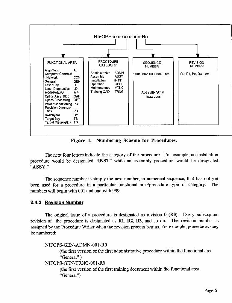
2.4 PROCEDURE NUMBERING SCHEME
NIF Operations Procedures are maintained by means of a numbering scheme which is organized by functional area as well as by type of procedure Each procedure is assigned an 1 l- to-13 digit number in accordance with the scheme outlined iu Figure 1
If a procedure contains any hazardous or dangerous processes, steps, or materials, the procedure will be given the letter “A” after the procedure number This follows the Nova convention. Each portion of the number is explained in the following sections.
2.4.1 Procedure Number
The first part of all NIF Operations Procedures numbers consists of the prefix NIFOPS, indicating that this is a NIF Operations Group procedure as opposed to a NIF Project procedure, facility install&ion, acceptance test, or operational test procedure.
The next two or three letters indicate what functional area the procedure is for For example, procedures related to the Laser Bay will be designated “LB” while general procedures such as those dealing with facility access will be designated “GEN”
Page 5
NIFOPS-xxx-xxxx-nnn-Rn I I I
I FUNCTIONAL AREA I I
PROCEDURE CATEGORY I I
SEQUENCE I I
REVISION NUMBER NUMBER I
Figure 1. Numbering Scheme for Procedures.
The next four letters indicate the category of the procedure For example, an installation procedure would be designated “INST” while an assembly procedure would be designated “ASSY.”
The sequence number is simply the next number, in numerical sequence, that has not yet been used for a procedure in a particular functional area/procedure type or category. The numbers will begin with 001 and end with 999.
2.4.2 Revision Number
The original issue of a procedure is designated as revision 0 (RO). Every subsequent revision of the procedure is designated as Rl, R2, R3, and so on. The revision number is assigned by the Procedure Writer when the revision process begins. For example, procedures may be numbered:
NIFOPS-GEN-ADMN-OOl-RO (the first version of the first administrative procedure within the functional area “General” )
NIFOPS-GEN-TRNG-OOl-RO (the first version of the first training document within the functional area “General”)
Page 6

These numbers are assigned by the Procedure Writer when a procedure is initiated
Page 7

2.4.3 Safetv Desianation
If a procedure contains any hazardous or dangerous processes, steps, or materials, the procedure will be given the letter “A” after the procedure number, indicating that Class A safety issues are present For example:
NIFOPS-GEN-ADMN-OOlA-R4
In addition, the “Hazards” section of the procedure will indicate the nature of the hazards (refer to Section 2 5, below)
2.5 PROCEDURE FORMAT
All procedures will be written in accordance with the NIF Operations Procedures Writer’s Guide, using the NIF Operations procedure template. A copy of the template is included in Appendix A. Each procedure will contain certain elements. These include
Overview: A brief description and/or purpose of the procedure and what personnel it is applicable to.
Hazards: Hazards associated with conducting the procedure, if any
Location: Description of the physical location where the procedure is to be performed
Applicable documents: Any documents that must be read prior to or as part of conducting the procedure or any references that may be useful.
Equipment required: Includes any equipment required to perform the procedure.
Estimated time required: An estimate of how long it will take to perform the procedure
Prerequisites: A list of prerequisites that must bc satisfied prior to the procedure beiig performed, including permission from other organizations or individuals, notification that must be provided to other organizations or individuals, prior training that may be required, as well as any other requirements not covered previously.
Procedure: A listing of the steps that comprise the procedure itself. This is the main body of the document.
Page 8

l Revision log: A table listing all revisions to the procedure with a brief description of what the revisions are
l Keywords: A list of key words that can be used to search for the procedure in the on-line NIF Operations Procedure System
NIF Operations Procedures may contain drawings, diagrams, illustrations, tables, checklists, and any other information pertinent to the procedure. Some of these documents may be in the PDM-I (Sherpa) database. Procedures may also refer to other procedures or documents. This information may be contained in the body of the procedure text, may bc included as appendices, or may be accessible from the procedure directly via electronic link (by clicking on the reference) Safety symbols, outlined in the NIF Operations Procedures W riter’s Guide, will be used as necessary
For many procedures, a checklist may be part of the procedure. This checklist would be a summary of the more detailed tasks or steps outlined in the procedure itself and be useful for operators who are familiar enough with the procedure to use a condensed version as a guide to performing all steps in the correct order The checklist may also serve as an interactive document which an operator may use to check off steps (on-line) as they are completed, and then fne electronically to ma intain a record of procedure completion
2.6 PROCEDURE DEVELOPMENT AND REVISION
All NIF Operations procedures will be written using a procedure template (refer to Appendix A) that identifies the procedure as a “NIF Operations” procedure Procedures will be developed through various draft stages with review cycles in between; all will require final approval by the procedure owner, NIF Operations Area Leader, Hazards Control, and the NIF Facility Manager (Prior to a formal NIF Operations organizational structure, the NIF Project Lead Engineer will have approval authority.) The process has been designed to off-load as much work as possible from NIF Project personnel Refer to F igure 2 for a flowchart of procedure development Detailed information on procedure development is provided in Section 2 6.1, below
As NIF Operations procedures require revision, a revision request (refer to Appendix B) will be submitted, and the procedure will be revised. The revision process is similar to the development process with fewer review cycles M inor revisions may require approval only, ma jor revisions may require one or more technical reviews Detailed information on procedure revision is provided in Section 2 6 2, below Exceptions to the standard guidelines of procedure development and revision are provided in Section 2 6.3
Page 9
r
2.6.1 Procedure DeveloDment
Typically, procedure development begins when the need for a procedure has been identified by a NIF Lead Engineer, NIF operator/technician, or other technical expert The steps, as outlined in the flowchart in Figure 2, are as follows
(1) The need for a procedure is identified by means of a NIF Operations Procedure Request form (refer to Appendix B for a copy) and a procedure title and general contents are specified The initial request may be come from any individual connected with that particular technical area Initially, as the facility is being built, NIF Lead Engineers will be responsible for approving requests for new procedures. As NIF systems and subsystems come on line, areas of responsibility will be assigned to NIF operators. They will then become procedure owners, taking full responsibility for ensuring that procedures exist and are correct and up-to-date.
(2) A rough draft is developed by the technical expert identified by the Lead Engineer or procedure owner in collaboration with the Procedure Writer. From this, the Procedure Writer then prepares the first formal draft by putting the rough draft into the proper format, checking grammar, and ensuring that good quality illustrations are included
(3) The first draft review will be conducted by technicians, technical experts, the NIF Operations Area Leader, LLNL Hazards Control, or any combination of those who are deemed to be appropriate by the Lead Engineer or procedure owner. This review is technical and user intensive and is designed to ensure technical accuracy and clarity. The emphasis during this review should be on technical aspects as well as clarity for users and not form, format, or editorial issues.
During any review cycle, reviewers may test the procedure as they deem appropriate.
(4) The results of the first review will then be incorporated into a second draft by the Procedure Writer.
Page 10

r
* Procedure Proc Owner or
titlelcontents Lead Engineer or
c
Writes b Write rough draft
edits
k Prepare first draft cal Experts, NIF Op Area Ldr,LLNL
Hazards Control
revisk3s - Prepare second draft Technicians and/or
Technical Expert
I comment
I
revises b Prepare final draft
Hazards Control.
* By this stage, a procedure owner will be assigned
Figure 2. Flowchart for Developing a Procedure.
Page 11

(5) The second draft review will be conducted by a subset of those who performed the initial technical review to ensure that all changes have been appropriately incorporated The original technical expert who collaborated on the first rough draft will participate in this step to ensure technical accuracy
(6) The results of the second review, if any, will then be incorporated into a final draft by the Procedure Writer
(7) The fd draft will be submitted for approval by the procedure owner, NIF Operations Area Leader, the NIF Facility Manager, and Hazards Control, if necessary
NOTE I
While reviews are technical in nature and concentrate on technical correctness and clarity, approvals are designed to emphasize overall appropriateness.
(8) The approved procedure will then be published on line (refer to Section 2 7)
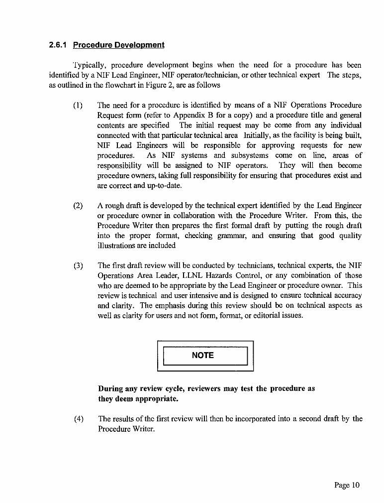
2.6.2 Procedure Revision
Procedures are revised in much the same manner as they are developed (refer to the flowchart in Figure 3). The need for a procedure revision is identified by the procedure owner by means of the NIF Operations Procedure Request form, and the procedure owner and Procedure Writer collaborate to revise the procedure For extremely complex procedure revisions, reviews comparable to those for a new procedure may be conducted; for minor changes, the review cycle may be skipped entirely. Approvals, however, are always required.
2.6.3 Exceptions
While the guidelines outlined above for procedure development and revision will typically be followed, there are circumstances that will dictate “short-circuiting” these guidelines. During early installation and operations, procedures may change frequently or rapidly as experience with equipment increases. Some procedures may be in the development stage as the equipment is being installed In such cases, interim procedures, which may be in the form of hand-written or marked up procedures, may be used with the approval of the area or shift supervisor pending formal publication of official procedures. Approval authority in these instances will be established as required
Page 12
At no time shall unapproved procedures be used.
Procedure revision requirement identified
I I 4
I Procedure revision b-/Procedure Owner /
writes ledlts Prepare first draft
I
TechniciansiTechni- cal Expert, NIF Op
Area Ldr, LLNL Hazards Control
Proc Owner, NIF Op revises
b Prepare final draft Area Ldr, LLNL
Figure 3. Flowchart for Revising Procedure.
Page 13
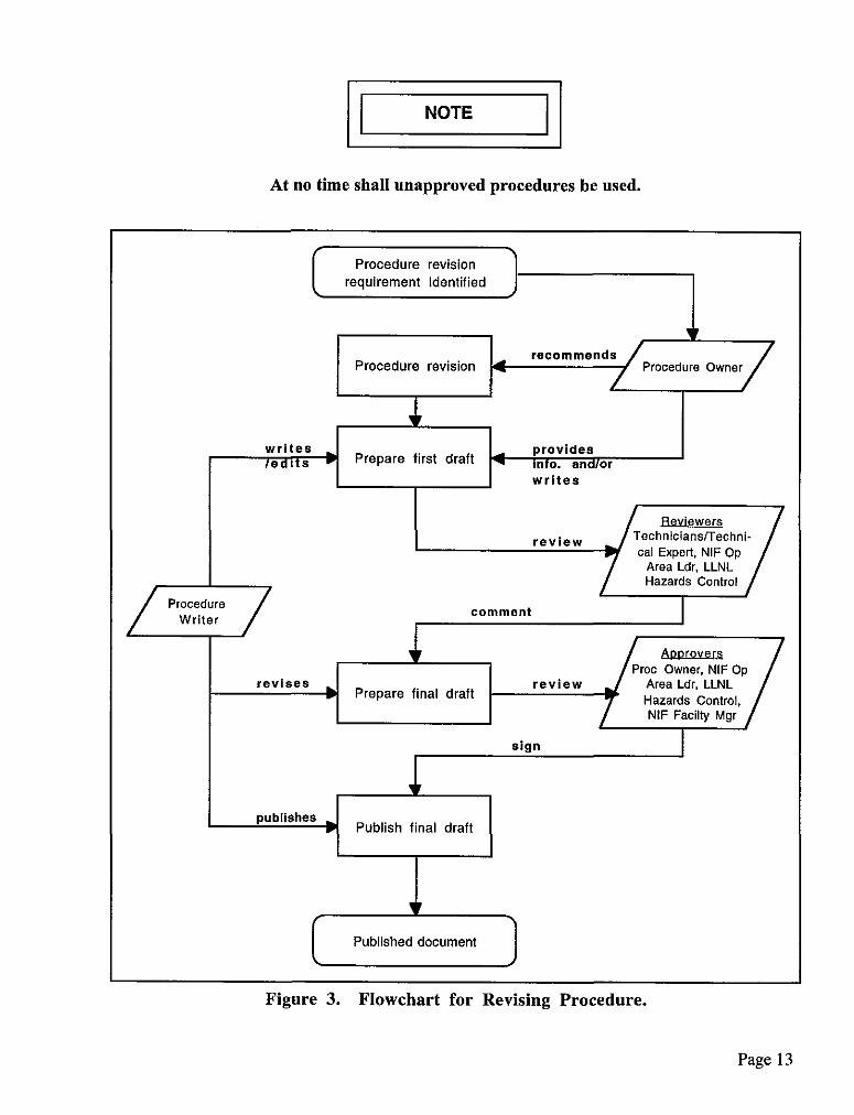
2.7 PROCEDURE PUBLICATION
All NIF Operations procedures will be published on-line, retrievable from various NIF computer sites. In addition, there will be retrieval capability between the NIF Operations Procedures System and the PDM-I and PDM-II data bases (refer to Figure 4) Access will be provided to all LLNL networked computers and authorized networked computers at a number of external locations including Los Alamos National Laboratory (LANL), Sandia National Laboratory (SNL), as well the University of Rochester/Laboratory for Laser Energetics
Figure 4. NIF Operations Procedures System Connectivity.
Page 14

2.7.1 NIF ODerations Procedures On-Line Svstem Functionality
The NIF Operations Procedure System will consist of a home page from which access is provided to all procedures There will be an index to all procedures as well as a search capability to enable a user to search by name, procedure number, topic, functional area, category, procedure owner, and key words. From the NIF Operations Procedure System, users will be able to access referenced documents in other data bases. Also, a path will be provided to prior revisions of procedures. Documents will be readable regardless of platform. Figure 5 is a diagram detailing the functionality of the system. Professional programmers will be used to develop the on-line system
All procedures will be available as Adobe Acrobat pdf files; references in procedures will be linked to other .pdf documents as required
r
Figure 5. NIF Operations Procedures System Functionality.
Page 15

r
2.7.2 NIF ODerations Procedures Specifications
The NIF Operations Procedure System will provide the following capability, the implementation details will be determined in the coming months
(1) GENERAL SPECIFICATIONS
l Home page. l Index of procedures by functional area and procedure category. l Read and print capability for any procedure or referenced document. l Edit and publish privileges for Procedure W riters only l Procedure configuration control (may be provided by PDM-I, Sherpa)
(2) MOVING THROUGH PROCEDURE SYSTEM
l Ability to jump from one page forward or backward or to return to home page. . Ability to access a reference (engineering drawings, other procedures,
document, forms, checklists) by clicking on that reference (including access to PDM-I and PDM-II data bases)
. Ability to return to ma in document from the reference document l Ability to “bookmark” procedures frequently used. l Ability to skip, within a document, to the next relevant section upon answering
yes/no.
(3) SEARCHING
l Ability to search by number or any portion of a procedure number. l Ability to search by functional area or procedure category or both l Ability to search by title or partial title l Ability to search by owner l Ability to search by “key words.”
Page 16
(4) DATE STAMPING
l Every unchanged procedure is automatically date stamped (period to be determined) with an “effective through <date>“ notation.
l Changed procedures bear the actual change date until the next automatic date stamping
l Alert when procedure needs to be reviewed (period to be determined). * Alert when a procedure is under revision.
(5) ARCHIVING
l Automatically archive earlier version when a revised procedure is installed l Archived (obsolete) procedures accessible with same search capability as
current ones
(6) ELECTRONIC LOGGING OF RESPONSES
l When a procedure contains a checklist, responses are logged (filed). l When a procedure contains interspersed questions which require answers
(yes/no, comments, etc ), the responses are logged (filed) l Ability to return to responses and make changes l Print capability for logged responses.
Page 17
3. RESOURCES AND SCHEDULE
3.1 INTRODUCTION
Due to the large number of NIF Operations procedures anticipated, resource planning and scheduling are critical factors These must be coordinated with the overall NIF facility design and construction schedule, taking into account when Operational Readiness Reviews are planned and when various systems or subsystems are either installed, activated, or operational. The following sections outline the resources required as well as a proposed schedule based on these factors
3.2 RESOURCES REQUIRED
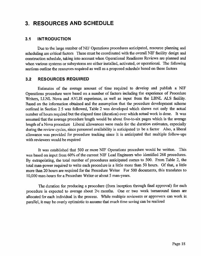
Estimates of the average amount of time required to develop and publish a NIF Operations procedure were based on a number of factors including the experience of Procedure Writers, LLNL Nova and AVLIS experience, as well as input from the LBNL ALS facility. Based on the information obtained and the assumption that the procedure development scheme outlined in Section 2 5 was followed, Table 2 was developed which shows not only the actual number of hours required but the elapsed time (duration) over which actual work is done. It was assumed that the average procedure length would be about five-to-six pages which is the average length of a Nova procedure Liberal allowances were made for the duration estimates, especially during the review cycles, since personnel availability is anticipated to be a factor Also, a liberal allowance was provided for procedure tracking since it is anticipated that multiple follow-ups with reviewers would be required
It was established that 500 or more NIF Operations procedure would be written. This was based on input from 60% of the current NIF Lead Engineers who identified 268 procedures. By extrapolating, the total number of procedures anticipated comes to 500. From Table 2, the total man-power required to write each procedure is a little more than 50 hours. Of that, a little more than 20 hours are required for the Procedure Writer For 500 documents, this translates to 10,000 man-hours for a Procedure Writer or about 5 man-years.
The duration for producing a procedure (from inception through linal approval) for each procedure is expected to average about 2% months. One or two week turnaround times are allocated for each individual in the process. While multiple reviewers or approvers can work in parallel, it may be overly optimistic to assume that much time saving can be realized
Page 18
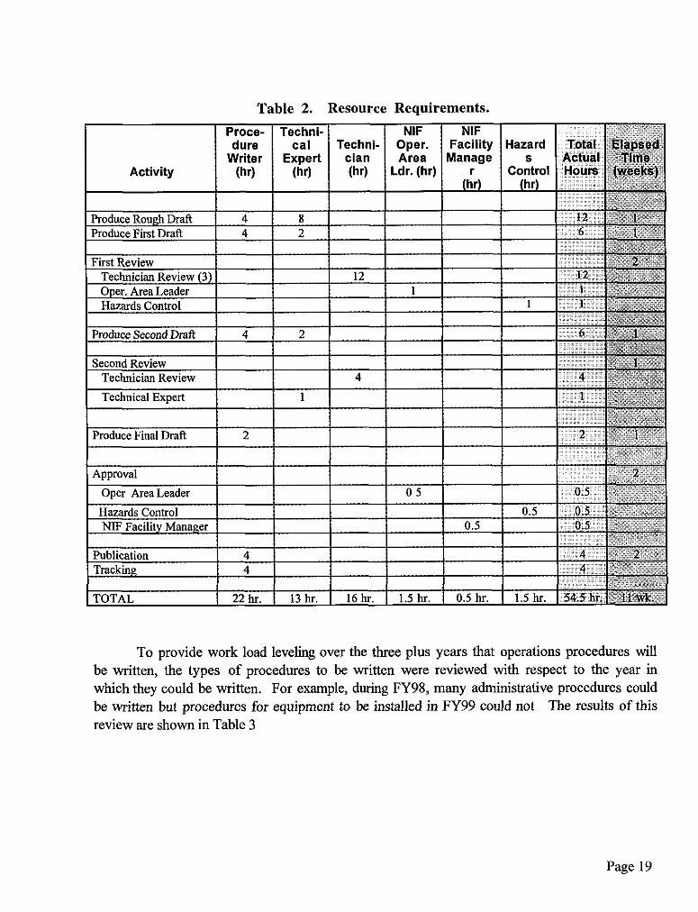
Table 2. Resource Requirements.
To provide work load leveling over the three plus years that operations procedures will be written, the types of procedures to be written were reviewed with respect to the year in which they could be written. For example, during FY98, many administrative procedures could be written but procedures for equipment to be installed in FY99 could not The results of this review are shown in Table 3
Page 19
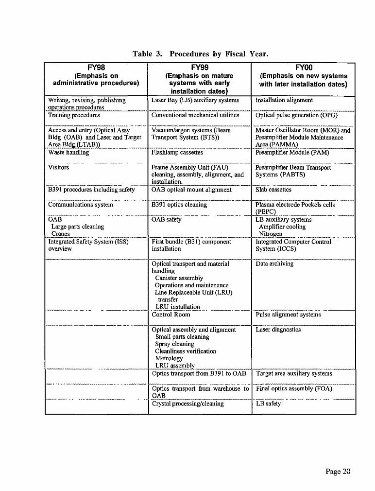
Table 3. Procedures by Fiscal Year.
r
(Emphasis on administrative procedures)
(Emphasis on newsy with later installation
Vacuum/argon systems (Beam Transport System (BTS))
-.--__-_-_ .-. ._._. _---- hmmmications system
Large parts cleaning C!rEXU% --_--_ _ - -~___~ &grated Safety System (ES) werview
--~__
Amplifier cooling ._.-
--- ----- -_
LRU installation
Optical assembly and alignment
Optics transport f?om B391 to OAB ..-. -.-.~-_^l__-. _ _ _-“-__l _~~
-F%al optics assembly (FOf
Page 20
Table 3. Procedures by Fiscal Year
FY98 (Emphasis on
administrative procedures)
__-- __.. _
.---. -_ -- --. ----
(continuedj. FY99
(Emphasis on mature systems with early installation dates)
surveying
First bundle (B31) controls __-_-~ ---.... .-_-
Safety interlock injection
Facility access -- .--_ _-_--
Power conditioning Installation Module test High-potting Capacitor bank safety
Optical mounts assembly/alignm~ --
Timing/fiducial system
Integrated Safety System (ISS) Safety interlocks
--- _^I~ Wave front control/adaptive optics
First wall Beam dumps Vacuum system
FYOO (Emphasis on new syste with later installation dat
Switchyard (SY) and Target An
__--_. _______ __ Precision diagnostics operation
Supervisory controls so&we
Communications system
Because the bulk of the procedures will have to by written in FYOO, it is imperative that as many procedures as possible be written in FY98 and FY99, even if those procedures are incomplete or partially tested at the time they are initially published.
3.3 SCHEDULE
A schedule showing tbe NIF Operations procedure writing effort is shown in Figure 6 The schedule provides key milestones in the planning phase and shows key NIF Projects tasks to indicate how procedure writing will fit into the overall NIF Project Schedule.
Page 2 1

r
I
Figure 6. NIF Project Schedule.
Page 22

4. PROCEDURES REQUIRED
4.1 INTRODUCTION
A number of procedures have been identified as being required for the NIF facility. These procedures include all functional areas as well as categories. Inputs, by WBS number, were solicited from all NIF Lead Engineers.
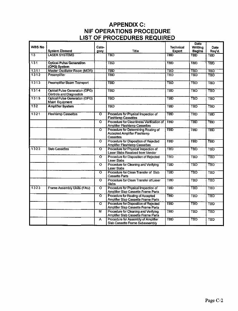
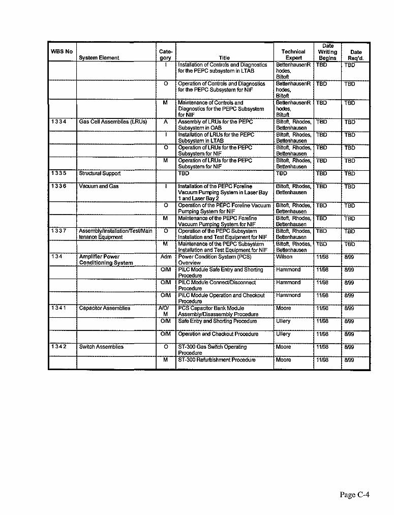
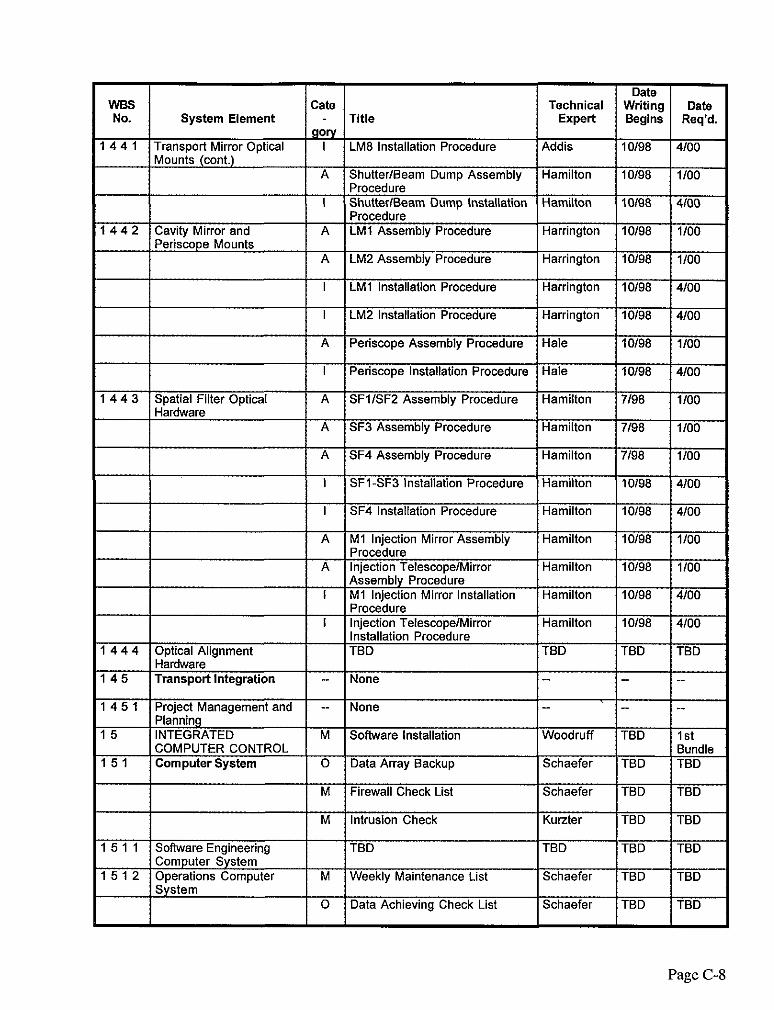
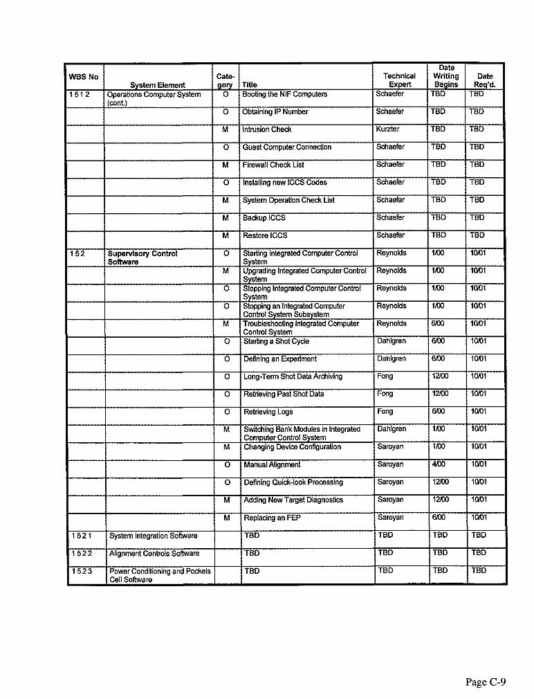
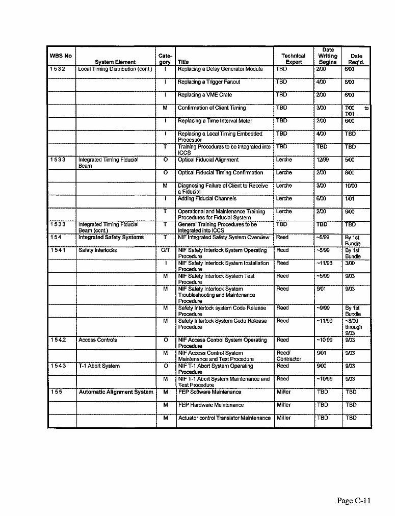
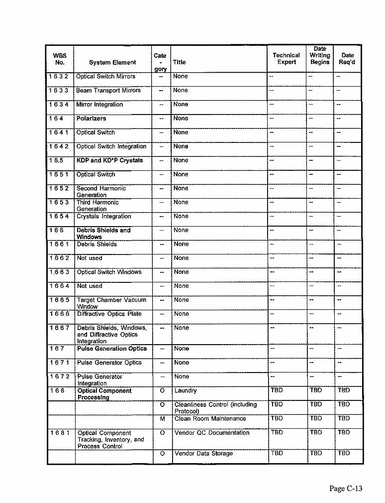
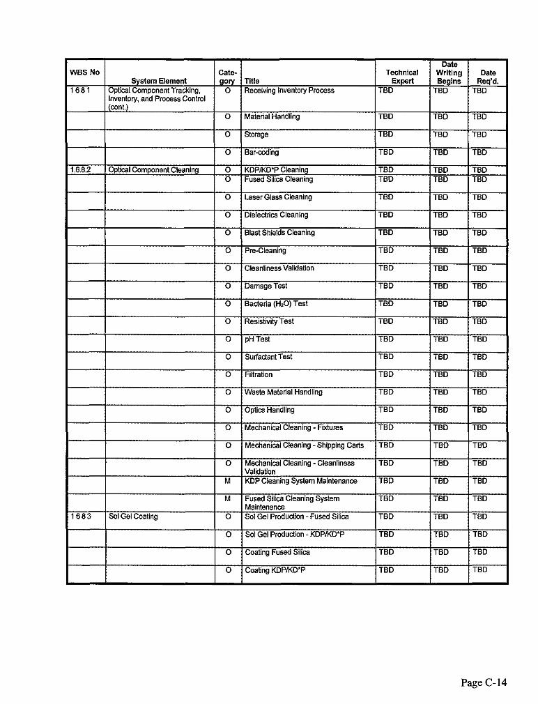
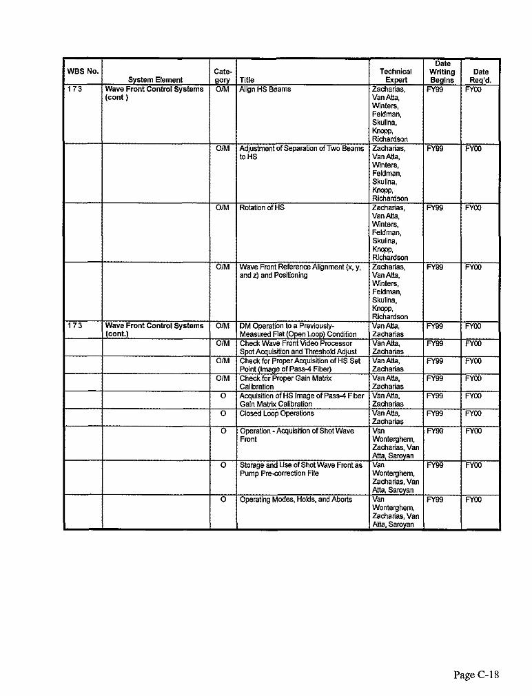
4.2 LIST OF PROCEDURES
Appendix C provides a list of all procedures identified by NIF Lead Engineers for each WE% level. They are specified by WEB number (to the fifth level) and by system element. Included is the title and the category of the procedure as well as the name of the technical expert responsible for the procedure. In addition, dates are provided indicating when procedure writing can begin and when it is required
For reference purposes and as an aid in developing a comprehensive list of NIF procedures, a list of Nova procedures titles is provided in Appendix D.
Page 23

5. TRACKING PROCEDURES
r
I
5.1 INTRODUCTION
The progress of the procedure development effort will be tracked throughout its lifetime. Due to the number of review cycles and the number of people that will be involved in this effort, it will be necessary to ensure progress continues uninterrupted In addition, the procedures themselves will be under configuration control
5.2 TRACKING TABLE
The progress of procedure development will be tracked by Procedure Writers via a spreadsheet. Such tracking is particularly important since there are Iirm deadlines, based on Operational Readiness Reviews and other milestones, and it is necessary to ensure that procedures continue to be developed and published on a regular schedule. In addition, reviewers and approvers will be reminded, if they are delinquent Table 4 shows what elements will be tracked for each procedure
5.3 PROCEDURE CONFIGURATION CONTROL
Contiguration control for all developed operations procedures will be provided through the PDM-I (Sherpa) dam base. This will ensure that once procedures are on line, revisions as well as periodic reviews will be tracked so that only the most current procedure is available in the active system
Page 24

Table 4. Operations Procedures Status Report.
FWlC- tional Area
-- __.__--
-_._I_
--
-~ ..~
_.-_ _ -----. - -,
___I.-
-------I ---I- ---I---l---&
Page 2.5
6. UPCOMING ACTIVITIES
During the second half of FY98, the following activities will be taking place with respect to NIF Operations procedures
(1)
(2)
(3)
(4)
(5)
(6)
The NIF Operations Procedures Plan will be coordinated with the NIF Training Plan
A comprehensive list of procedure titles has been solicited from all NIF Lead Engineers to build a complete list of the procedures required.
Schedules for procedure development based on project staff input will be developed and integrated into the overall plan.
NIF Procedure Writers will begin working with programmer, PDM-I and PDM-II data base personnel, and/or system administrators to develop an on-line system for NIF Operations procedure retrieval and configuration control
Forms will be finalized and made available on servers
The first group of procedures will be written and brought on-line.
Page 26

APPENDICES

r
APPENDIX A:
PROCEDURE TEMPLATE
Page A- 1

APPENDIX A: PROCEDURE TEMPLATE
To assist Procedure Writers, a procedure template has been developed which contains the “boiler plate” or standard elements required in all procedures Figure A-l shows the standard procedure template. The template is available on-line on the NIF server and is entitled kocedure T&plate.
.&$ ?s@$; P:?
NIF OPERATIONS PROCEDURE Title:
NIFOPS- 12116/97
Page 1 of
Functional Am
Prepared by: Date Approved by: Date: Approved by: Date:
Functional Area Leader NlF Facility Manager
Procedure Owner Hazards Control (if necessary)
NOTE: See last page for Revision Log.
Other
1. OVERVIEW 2. HAZARDS 3. LOCATION 4. APPLICABLE DOCUMENTS (click on document name to view) 5. EQUIPMENT REQUIRED 6. ESTIMATED TIME REQUIRED 7. PREREQUISITES 7.1 Permission Reauired 7.2 Notification Reauired 7.3 Trainina Reauired 7.4 Other Reauirements 6. PROCEDURE 6.1 Definitions 8.2 [Begin procedure text]
Page A-2
I levision LI Rev. No.
0 Effective Date ‘ages Affected
All Brief Description of Revision
)riginsl issue.
Page A-3
APPENDIX B:
NIF OPERATIONS PROCEDURE REQUEST FORM
Page B-l

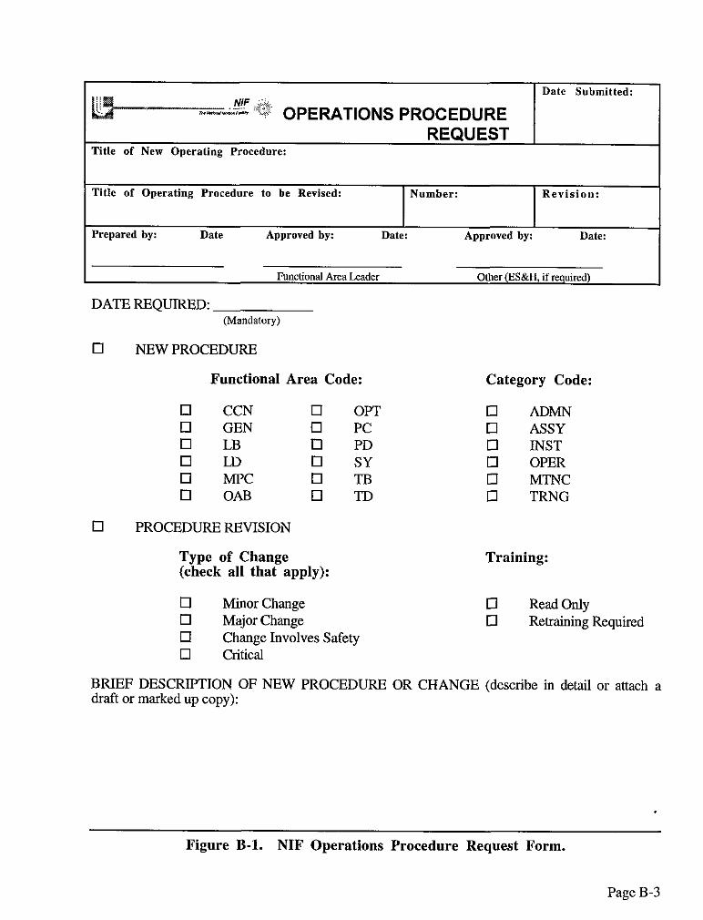
APPENDIX B: NIF OPERATIONS PROCEDURE
REQUEST FORM
To create a new or revise an existing procedure, a NIF Operations Procedure Request form should be used. Figure 7 shows a standard Request Form. The electronic version of the form is available on-lie on the NIF server and is entitled Procedure Request Form
Page B-2
Date Submitted: i i@ o,,E~,-lONS PROCEDURE
REQUEST Title of New Operating Procedure:
Title of Operating Procedure to be Revised: Number: Revision:
Prepared by: Date Approved by: Date: Approved by: Date:
Functional Area Leader Other (ES&H, if required)
DATE REQUIRED: (Mandatory)
0 NEW PROCEDURE
Functional Area Code:
0 CCN cl OPT 0 GEN q PC q LB q PD 0 LD 0 SY 0 MPC 0 TB q OAB 0 TD
0 PROCEDURE REVISION
Type of Change (check all that apply):
0 M inor Change 0 Major Change q Change Involves Safety 0 critical
Category Code:
0 ADMN 0 ASSY 0 INST 0 OPER q MTNC q TRNG
Training:
0 Read Only 0 Retraining Required
BRIEF DESCRIPTION OF NEW PROCEDURE OR CHANGE (describe in detail or attach a draft or marked up copy):
Figure B-l. NIF Operations Procedure Request Form.
Page B-3

APPENDIX C:
NIF OPERATIONS PROCEDURE LIST OF PROCEDURES REQUIRED
Page C- 1
APPENDIX C: NIF OPERATIONS PROCEDURE
LIST OF PROCEDURES REQUIRED
r
I
Page C-2

1331 Switch Pulse Generators (SPG) I Installation of PEPC SPG Radcs in Rhodes, TSD TED LTAB Biitoft.
Bettenhausen 0 Operation of PEPC SPGs for NIF Rhodes, TED TED
Sikoft, Settenhausen
M Maintenance of PEPC SPGs for NIF Rhodes, TSD TED Sinoft, Settenhausen
1332 Plasma Pulse Generators I Installation of PEPC PPG Rade in Rhodes, TBD TED 6-G) LTAB Sinoft.
Eettenhawn 0 Operation of PEPC PPGs for NIF Rhodes, TED TED
Binoft. Bettenhausen
M Maintenance of PEPC PPGs for NIF Rhodes, TSD TED Biltoft, Settenhawn
1333 Pock& Cell System Controls A Assembly of Controls and Diagnostics SettenhausenR TED TED and Diagnostics for the PEPC Subsystem in LTAS hm3.x
Binoft
Date NBS No cate- Technical Writing Date
System Element gory Title Expert Begins Req’d. I324 Supporl Hardware TED TED TBD TED
0 Disposition of Rejeded LRU TSD TED TED
133 Pock& Cell System TBD TBD TBD TSD
Page C-3
I I I I M ST-300 Refurbishment Procedure MOOR H&3 &s9
Page C-4

r
I
SYSTEMS
Page C-5

v
1
1 1 1
1
1
1
1
1
1
1
1
424 Gas Handling Systems (Argon) I Installation of the BTS figson System Mukheji. TBD TBD Hitchcodn, Karken. Valderama. Reed, Wang
0 Operation ofthe BTS Argon System Mukheji. TBD TBD Hitchcock, Karlsen. Valdeama, Wang
M Maintenance of the BTS Argon System Mukherji. TBD TBD Hitchcock, Karlseen. Vatderama, Wang
425 Conventional Utilitiis I Installation of the NIF Conventional DellSkY, TBD TBD (Mechanic@ Mechanical Utilities System HitchC0&,
~EY”~ 0 Operatiin ofthe NIF Conventional DellSky, TBD TBD
Mechanical Utilities System Churchill, Hitchcock
M Maintenance of the NIF Convenfonal Denstey. TBD TBD Mechanical Utilllies System Churchill,
Hitcha& 426 AssemblyllnstallationrresVMain I Installation ofthe NIF Spedal Equipment Reed. TBD TBD
tenance Equipment Hitchcock
Page C-6

Mezzanines 143 14 As%?mbtyilnstallationJF&fMain -- None
tenance Equipment 1432 Laser Bay Support Stnrdures -- NOR-3
StrudUPSS 14327 Laser Bay Catwalks and __ NOI% ._ __ __
Mezzanines 1 4 3 2 6 Assembly/lnstallatio~es~ain -- NOW __ __ __
tenance Equipment 144 Optical Mounts TBD TBD TBD TBD
1441 Transport Mirror Optical A LM4 (up facing) Assembly Procedure Chamben 7,96 IIWI MOUiltS
A LM4 (down facing) Assembly Procedure Chambers 796 l&l
A LM5 (up facing) Assembly Procedure Chambers 10198 1100 I I I I I 1 A 1 LM5 (downfadng)AssemblyProcedure 1 Chamben j 1096 1 IM)
I LM4 installation Prcedure Chamben 1096 402 I
Page. C-7
r
1 5 1 1 Ti3D Ti3D TED TED Computer System
1 5 1 2 Operat ions Computer M Weekly Maintenance List Schaefer TED TED System
0 Data Achieving Check List Schaefer TED TED
Page C-8
NBS No cat* System Element gory Title
,5 12 I Operations Computer System I 0 / Boating the NIF Computers (cont.)
0 Obtaining IP Number
M Intrusion Che&
0 Guest Ccmputer Connection
M Firewall Check List
0 Installing new ICCS Codes
M System Operation Check List
M B&up ICCS
M Restore ICCS i
152 supelvisoly Control 0 SOffwa~
PST;; Integrated Computer Control Y
M Upgrading Integrated ComputerControl System
0 Stopping Integrated Computer Control System
0 Stcppirq an Integrated Computer Control System Subsystem
M Tmubteshooting Integrated Computer Control System
0 Starting a Shot Cycle
M Switching BankModules in Integrated Computer Control System
M Changing DeviceCon~uratian
0 ManualAl@vrent
0 Defining Quick-look Processing
M Adding New Target Diagnostics
M Replating an FEP
1521 System Integration Sofware TBD
1522 Alignment Controls Software TBD
1523 Power Conditioning and Pod& TBD Cell sofware
Page C-9

iming of Diagnostic Instruments (20
Page C-10
r
Page C- 11

Page C-12
r
Page C-13
nventory. and Process Control
Sol Gel Prcdudion -Fused Silica
0 Sol Gel Pmdudion - KDPiKD’P TBD TBD TBD
0 Coating Fused Silica TBD TBD TBD
0 Coating KDP/KD*P TBD TBD TBD
Page C-14

0 Load Testing TBD TBD TBD
0 Cleanliness Control TBD TBD TBD
0 Vibration Analysis TBD TBD TBD
Page C-15

r
I
mblyPa&aging/ Handl ing
Page C-16

Page C-17
0 Acquisaion of HS Image of Pass-l Fiber Van Atta. FY59 Gain Matrix Calibration ZXhWklS
0 Closed LOOP Operations Van AUa, FY99 Fyw ZClCh~d~S
0 Operation-Acquisition of Shot Wave Van FY99 FYW Fmnt Wonterghem.
zadlallas. van Atta, Samyan
0 Storage and Use of Shot Wave Front as Van FY93 Fro0 Pump Premrrection File Wonterghem.
Zacharias, Van Atta, Samyan
0 Operating Modes. Holds, and Aborts Van FY52 FYW Wonteghem. zacharias, van At&, Samyan
Page C-18

I I 1812 1FintWall AiMA Removal and Installation of Target Hibbard TBD TED
_..l...l_l .%st Wall Panels O/M In~+~&on and Maintenance of Laser Hibbard TBD TBD
I Beam Dumps 1813 NeuiroiVGamma Ray Shielding TBD TBD TBD TBD
Page C-19

Page C-20

Page C-21

Page C-22

Page C-23

Date WBS No. cat.3 Technical Writing Date
System Element gory Title mpefi Begins Req’d. 1922 Switchyard Loading (ant ) VO Roving Mirrors Installation HOttOll TBD TBD
VO Precision Optics Installation HOltOIl TBD TBD
!/O Beam Shutters Installation HOltOil TBD TBD I I I I I t
1923 Target Area Leading A Target Area Delivery System Assembly Ho-ton TBD TBD I
0 Subassembly and Component Fttres Simmons TBD ?m
19321 OpticTransfer A Optic Receiving Wong TBD ml
19 3 2 2 Mechanical Transfer A Mechanical Receiving ww TBD 3m
0 Mechanical Gross Small Parts Cleaner Wong TBD L?.cQ I t I , I 1 0 [ Mec&%nical Gross Large Park Cleaner / Wang 1 TBD WI 1 M 1 Mechanical Gross Small Parts Cleaner / Wong 1 TBD 13/w I
Page C-24

r
Page C-25

1 IO 2 4 Requirements/interface -- None .- __ Control
1 10 2 5 1 System Engineering _. NOM __ __ __ I I I I I I
1 10 3 1 Ll~~~ioval Readiness __ None __ __ __
meional -- None __ __
I I I I I I 11042 Cluster 1 __ None ._
Legend: A Assembly TBD To be determ ined I Installation None No procedures required at this time M Maintenance 0 Operating T Training
Page C-26

APPENDIX D:
LIST OF NOVA PROCEDURES
Page D-l

r
APPENDIX D: LIST OF NOVA PROCEDURES
Procedure T itle Area Category
Sweep System and Procedure Sating Procedure for Rod Amplifiers Laser Diagnostic Spool and Laser Beamline Access Low-level Waste Handling and Packaging Ion Pump Procedure Procedure for Opening NZ-tilled Beam Tubes and Pipes Target Chamber Access, Securing, and Entry Procedures Power-Conditioning Substation and Safety Procedures Gastech Model OX-82 Oxygen Monitor Procedure. for Handling Parts that are Potentially Contaminated with Tritium
Bldg 391 Bldg 391 Bldg 391 Bldg 391 Bldg 391 Bldg 391 Bldg 391 Bldg 391 Bldg 391 Bldg 391
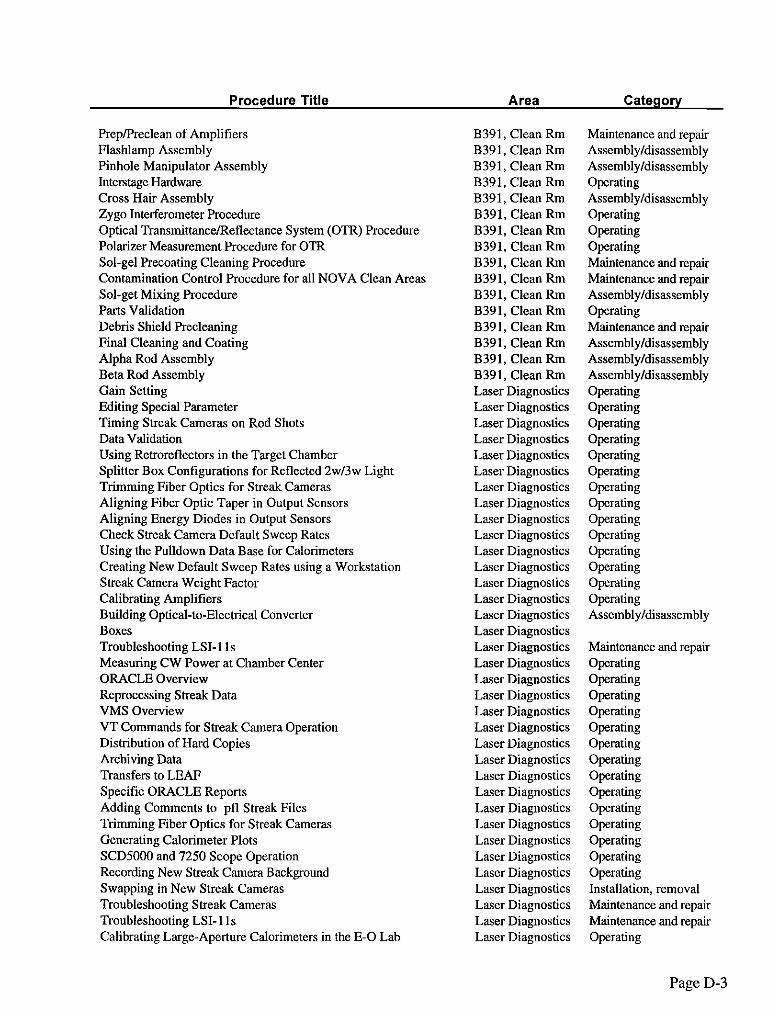
Procedure for Regenerating Target Chamber Cryo Pumps Bldg 391 Bicron 505 Spill Procedure Bldg 391 Pre-Lift Inspection Checklist for Manbasket Bldg 391 Amplifier Installation and Removal Checklists B391, Clean Rm Disk Cleaning and Inspection B391, Clean Rm Flashlamp Test Procedure B391, Clean Rm Turning Mirror Assembly B391, Clean Rm Polarizer and Splitter Assembly B391, Clean Rm Polarizer and Splitter Disassembly B391, Clean Rm Faraday Rotators B391, Clean Rm Amplifier Assembly B391, Clean Rm KDP Cleaning and Inspection B391, Clean Rm Debris Shield RemovaliInstallation Checklist B391, Clean Rm Focus Lens RemovaVInstallation Checklist B391, Clean Rm Sol-gel Coating (AR Dip Coating) B391, Clean Rm Monthly Chamber Cleaning Procedure B391, Clean Rm AAP operation Procedure B391, Clean Rm Lens Positioner B391, Clean Rm Center Mirror Spool B391, Clean Rm Operating B391, Clean Rm Amplifier Disassembly B391, Clean Rm Target Positioner B391, Clean Rm Chamber Entry 839 1, Clean Rm Vacuum System Operations B391, Clean Rm COMS Certification B391, Clean Rm Crystal Array Assembly B391, Clean Rm Crystal Array Disassembly B391, Clean Rm Silicon Dip Coating B391, Clean Rm Silicon Curing B391, Clean Rm Phase. Plate Pwcleaning B391, Clean Rm Spray Booth Procedure B391, Clean Rm Clean Room Laundry B391, Clean Rm Rod Cleaning and Inspection B391, Clean Rm
Maintenance and repair Operating Operating Maintenance and repair Operating Operating Opxating Operating Operating operating
operating Operating OpLming Maintenance. and repair Maintenance and repair opmtting Assembly/disassembly Assembly/disassembly Assembly/disassembly Operating Assembly/disassembly Assembly/disassembly Maintenance and repair Maintenance and repair Assembly/disassembly Maintenance and repair operating Operating Operating Operating Assembly/disassembly Operating Maintenance and repair Operating Operating Assembly/disassembly Assembly/disassembly Assembly/disassembly Assembly/disassembly Maintenance and repair Maintenance and repair Maintenance and repair Maintenance and repair
Page D-2
r
Procedure T itle Area Category
Prep/Preclean of Amplifiers Flashlamp Assembly Pinhole Manipulator Assembly Intelege Hardware Cross Hair Assembly zygo Interferometer Procedure Optical Transmittance/Reflectance System (OTR) Procedure Polarizer Measurement Procedure for OTR Sol-gel Precoating Cleaning Procedure Contamination Control Procedure for all NOVA Clean Areas Sol-get Mixing Procedure Parts Validation Debris Shield Precleaning Final Cleaning and Coating Alpha Rod Assembly Bet” Rod Assembly Gain Setting Editing Special Parameter Timing Streak Cameras on Rod Shots Data Validation Using Retroreflectors in the Target Chamber Splitter Box Configurations for Reflected 2.43~4 Light Trimming Fiber Optics for Streak Cameras Aligning Fiber Optic Taper in Output Sensors Aligning Energy Diodes in Output Sensors Check Streak Camera Default Sweep Rates Using the Pulldown Data Base for Calorimeters Creating New Default Sweep Rates “sing a Workstation Streak Camera Weight Factor Calibrating Amplifiers Building Optical-to-Electrical Converter BOXS Troubleshooting LX-1 1s Measuring CW Power at Chamber Center ORACLE Overview Reprocessing Streak Data VMS Overview VT Commands for Streak Camera Operation Distribution of Hard Copies Archiving Data Transfers to LEAF Specific ORACLE Reports Adding Comments to pfl Streak Files Trimming Fiber Optics for Streak Cameras Generating Calorimeter Plots SCDXKIO and 7250 Scope Operation Recording New Streak Camera Background Swapping in New Streak Cameras Troubleshooting Streak Cameras Troubleshooting LSI-11s Calibrating Large-Aperture Calorimeters in the E-O Lab
B391, Clean Rm B391, Clean Rm B391, Clean Rm B391, Clean R”I B391, Clean Rm B391, Clean Rm B391, Clean Rm B391, Clean Rm B391, Clean Rm B391, Clean Rm B391, Clean Rm B391, Clean Rm B391, Clean R”I B391, Clean Rm B391, Clean Rm B391, Clean Rm Laser Diagnostics Law Diagnostics Laser Diagnostics Laser Diagnostics Laser Diagnostics Laser Diagnostics Laser Diagnostics Laser Diagnostics Laser Diagnostics Laser Diagnostics Laser Diagnostics Laser Diagnostics Laser Diagnostics Laser Diagnostics Laser Diagnostics Laser Diagnostics Laser Diagnostics Laser Diagnostics Laser Diagnostics Laser Diagnostics Laser Diagnostics Laser Diagnostics Laser Diagnostics Laser Diagnostics Laser Diagnostics Laser Diagnostics Laser Diagnostics Laser Diagnostics Laser Diagnostics Laser Diagnostics Laser Diagnostics Laser Diagnostics Laser Diagnostics Laser Diagnostics Laser Diagnostics
Maintenance and repair Assembly/disassembly Assembly/disassembly Operating Assembly/disassembly Operating Operating Operating Maintenance and repair Maintenance and repair Assembly/disassembly Operating Maintenance and repair Assembly/disassembly Assembly/disassembly Assembly/disassembly Operating operating operating Operating Operating Operating Operating Operating Operating Operating Opming Operating Operating operating Assembly/disassembly
Maintenance and repair operating operating operating operating Operating Operating Operating Operating Operating Operating Operating Operating Operating Operating Installation, removal Maintenance and repair Maintenance and repair Operating
Page D-3

r
I
Procedure T itle Area Category
44cm Calorimeter Calibration Operating Streak Software OTDR Overview Rebooting DEPs and J33Ps Rebooting LDCONs Retrieving Past Shot Information Selecting Streak Lineonts Setting up for Propagated Rod Shots Spool Cluster Alignment SRS Delay Generator Operation SRS HV Power Supply Operation 44 cm Calorimeter Rebuild Changing Calorimeters Changing Spectrometer Operations Switchyard Spectrometer Operation Load to ORACLE Updating Sensttwtttes Changing Fast Timing Channels Calculating and Setting filter Wheels Calibration Laboratory Operation Calibration Shot Calorimeter Setup Changing Sweep Cards Comb Generator Operation Long Pulse Oscillator Alignment Broadband Oscillator (BBO) Alignment Spectrometer Streak Camera Setup (MPL,MFD) Diode Calibration HP Digitizer Tektronix SCDSOOO Scope CW Head Rebuild Oscillator Heads Rebuild Rod Amplifiers Rebuild Chiller Power-up and Power-down Stop-Charge Power Supplies SMC Device Mapping Multiple Set Point Mapping Optical Component Index and Layout Len Relay Chirper Beamline Alignment Setup for Long Pulse Shot Setup for Shot Pulse Shot Long Pulse Shot with Long Pulse Backlight Long Pulse Shot with Short Pulse Backlight Short Pulse Shot with Long Pulse Backlight Short Pulse Shot with Short Pulse Backlight Setup for Broadband!XPM Shot Setup for Pulse Compressing/4w Probe Shot MOR Startup Lamp Driver Startup, Sating, and Safeout Authorization Requirements List
Laser Diagnostics Operating Laser Diagnostics Operating Laser Diagnostics Operating Laser Diagnostics Operating Laser Diagnostics Operating Law Diagnostics Operating Laser Diagnostics Operating Laser Diagnostics Operating Laser Diagnostics Operating Laser Diagnostics Operating Laser Diagnostics Operating Laser Diagnostics Maintenance and repair Laser Diagnostics Installation, removal Laser Diagnostics Installation, removal Laser Diagnostics operating Laser Diagnostics operating Laser Diagnostics Operating Laser Diagnostics Operating Laser Diagnostics Operating Laser Diagnostics 0perati”g Laser Diagnostics Operating Laser Diagnostics Installation, removal Laser Diagnostics Operating MOR Opxating MOR Operating MOR Operating MOR operating MOR Operating MOR Operating MOR Operating MOR Maintenance and repair MOR Maintenance and repair MOR Maintenance and repair MOR operating MOR Operating MOR Operating MOR Operating MOR Operating MOR Operating MOR Operating MOR Operating MOR Operating MOR Operating MOR Operating MOR Operating MOR Operating MOR Operating MOR Operati”g MOR Operating MOR Operating
Page D-4

Procedure Title Area Category
Lamp Driver Safeout Shot Checklists Amplifier Safeo”tmeplacement/Alignment Energy Limits Pulse width vs Damage Threshold Short Pulse and FIDU Oscillator Alignment SF6 Gas Handling Illumination Beamline Alignment Pulse Chargers Polarizer Test Station CW Alignment Long Pulse Beamline Alignment including Shaper/Slicer Short Pulse Beanline Alignment and Short Pulse Backlight Alignment FIDU Beamline Alignment BBO/XPM Beamline Alignment Pulse Compression/4w Probe Beamline Alignment Film Calibration Station Nova Power Conditioning Proficiency Certification Lampdriver wing KVA Fanont Sting Procedure KVA Power Supply Safing Procedure MVA Fanout Safing F’rocedure Ignitron Sating Procedure Ignitron Hi-potting Procedure Laser Bay Hi-pot Testing Checklist MOR Power Supply Safeout Checklist MOR PFN Safing Target Chamber Entry TBLDS Pumping/Venting Returning the Target Inserter to Normal Chamber Pumpdow” TBLDS Removal/Installation of Debris Shields, and Phase Plates Target Short Checklist Monthly Chamber Cleaning RemovaVInstallation of the Primary Focus Lens Target Inserter Restating the Vacuum Control System Monthly Rack Maintenance Restating the Conflict System Soft X-Ray Framing Camera (SXFRC) High-Bandwidth Digitizer Operation Dante X-Ray Diagnostic Gated X-Ray Image (GXI) French X-Ray CCD Pinhole Camera Large Neutron Scintillator Array (LaNSA) Neutron Emission Time (NET) Fiducial Setup Time Gated Opacity Spectrometer (TOPS) Setup Tritium Handling
MOR Operating MOR Operating MOR Maintenance and repair MOR Operating MOR Operating MOR Operating MOR Operating MOR Operating MOR Operating MOR 0perati”g MOR Operating MOR operating
MOR Operating MOR Operating MOR Operating MOR Operating Pwr Conditioning Operating Pwr Conditioning Operating Pwr Conditioning Operating Pwr Conditioning Operating Pwr Conditioning Operating Pwr Conditioning Operating Pwr Conditioning Operating Pwr Conditioning Operating Pwr Conditioning Operating Pwr Conditioning Operating Target Bay Operating Target Bay Operating Target Bay operating Target Bay Operating Target Bay Maintenance and repair Target Bay Operating Target Bay Maintenance and repair Target Bay Maintenance and repair Target Bay Operating Target Diagnostics Operating Target Diagnostics Maintenance and repair Target Diagnostics Operating Target Diagnostics Operating Target Diagnostics Operating Target Diagnostics Operating Target Diagnostics Operating Target Diagnostics Operating Target Diagnostics Operating Target Diagnostics Operating Target Diagnostics Operating
Operating
Page D-5

APPENDIX E:
LIST OF ACRONYMS AND DEFINITIONS
Page E-l

A
ADMN
AL
ALS
ASSY
ATP
AVLIS
BTS
Category
CEBAF
CCN
APPENDIX E: LIST OF ACRONYMS AND DEFINITIONS
r
Letter “A,” safety designation the NIF Operations procedure numbering scheme It appears right after the procedure number (and before the revision number) indicating that “Class A” safety issues are present.
Administrative; a procedure category designation in the NIF Operations procedures numbering scheme
Alignment; a functional area designation in the NIF Operations procedures numbering scheme
Advanced Light Source, located at LBNL, Berkeley, CA.
Assembly; a procedure category designation in the NIF Operations procedures numbering scheme
Acceptance Test Procedure
Atomic Vapor Laser Isotope Separation (a Uranium isotope separation facility, located at LLNL)
Beam Transport System
Term delineating the type of procedure (e.g., administrative, installation, assembly, etc.), defmed in the NIF Operations procedure numbering scheme.
Continuous Electron Beam Accelerator Facility, located at Jefferson Lab, in Newport News, Virginia.
Computer Controls/Network; a functional area designation in the NIF Operations procedures numbering scheme.
Page E-2
DOE US Department of Energy, funding and oversight agency for NIF
EandF
FAU Frame Assembly Unit
First Bundle Refers to the first bundle of eight laser beams (B31) that will be brought on-line (also referred to as 1 st Bundle).
FOA Final Optics Assembly
Functional Area Term delineating an operational, physical, or systems area of the NIF Project (es., LB for Laser Bay, CCN for Computer Controls/Network), defined in the NIF Operations procedure number scheme.
GandH
GEN General, a functional area designation in the NIF Operations procedures numbering scheme that is not system or area specific
r
ICCS Integrated Computer Control System
ICF Inertial confinement fusion.
INST Installation, a procedure category designation in the NIF Operations procedures numbering scheme
ISS Integrated Safety System
L
Jefferson Lab Located in Newport News, Virginia, site of the Continuous Electron Beam Accelerator Facility (CEBAF)
Key Word A word identified as a primary word that can be used to search the NIF Operations procedure on-line system for a particular procedure document
Page E-3
LANL
LB
LBNL
LD
LLNL
Los Alamos National Laboratory, located in Los Alamos, NM, and one of the four laboratories involved in the development of NIF.
Laser Bay; a functional area designation in the NIF Operations procedures numbering scheme.
Lawrence Berkeley National Laboratory, located in Berkeley, CA.
Laser Diagnostics, a functional area designation in the NIF Operations procedures numbering scheme
Lawrence Livermore National Laboratory, located in Livermore, CA, and one of the four laboratories involved in the development of NIF as well as the site of that facility.
r
LTAB Laser and Target Area Building
Lead Engineer A position in the NIF Project having overall responsibility for a particular system element (at the third level of the WBS) from engineering design through acceptance testing
LRU Line Replaceable Unit
MOR
MP
Master Oscillator Room, an area in NIF where pulse generation is initiated.
MOR/PAMMA, a functional area designation in the NIF Operations procedures numbering scheme.
MTNC
NIF
NIFOPS
Maintenance, a procedure category designation in the NIF Operations procedures numbering scheme
National Ignition Facility, located at LLNL.
NIF Operations, a prefix of the NIF Operations procedures numbering scheme indicating that the procedure is part of NIF Operations (and not, for example, NIF Project Procedures, Operational Test Procedures, or Acceptance Test Procedures).
Page E-4

Nova
OAB
OP
OPER
OPG
ORR
OTP
PABTS
PAM
PAMMA
PC
PCS
PD
N (cont%ued)
r
An existing laser facility (precursor to NIF) operating at LLNL, Livermore, CA.
Optics Assembly Building, a functional area designation in the NIF Operations procedures numbering scheme
Optics Processing, a functional area designation in the NIF Operations procedures numbering scheme
Operating, a procedure category designation in the NIF Operations procedures numbering scheme
Optical Pulse Generation
Operational Readiness Review
Operational Test Procedure.
Preamplifier Beam Transport System
Preamplifier Module
Preamplifier Module Maintenance Area
Power Conditioning; a functional area designation in the NIF Operations procedures numbering scheme
Power Conditioning System
Precision Diagnostics, a functional area designation in the NIF Operations procedures numbering scheme.
Page E-5

PDM-I or PDM-II
PEPC
Procedure Owner
Procedure Writer
SLAC
SNL
SY
T-l
TB
TD
Technical Expert
TRNG
P (con tin ued)
Product Data Management-I system is a computer data base used to track NIF design and construction (trade name Sherpa); Product Data Management -11 is a new system, yet to be procured, which will function as a NIF Operations data base
Plasma Electrode Pockels Cells
A NIF Operations staff person, typically an operator, who is responsible for maintaining the accuracy of a given procedure
An engineer responsible for developing NIF Operations procedures in collaborations with Lead Engineers or technical experts
0, R, and S
Stanford Linear Accelerator Center, Stanford University, Stanford, CA
Sandia National Laboratory, located in Albuquerque, NM, and Livermore, CA, and one of the four laboratories involved in the development of NIF
Switchyard, a functional area designation in the NIF Operations procedures numbering scheme
Reference to time, T- 1 seconds, when Abort System can shut down a shot
Target Bay; a functional area designation in the NIF Operations procedures numbering scheme
Target Diagnostics; a functional area designation in the NIF Operations procedures numbering scheme
An engineer who is an expert in that particular area and who may or may not be part of the NIF Project
Training, a procedure category designation in the NIF Operations procedures numbering scheme
Page E-6

UR/LLE
USDOE
WBS
U, V, W, X, Y, and Z
University of Rochester, Laboratory for Laser Energetics, located in Rochester, NY, and one of the four laboratories involved in the development of NIF.
See DOE
Work breakdown structure, a numbering scheme used to identify discreet design areas of the NIF Project, also used for budgeting and reporting purposes.
r
Page E-7