
the millau viaduct
21
THE MILLAU VIADUCT Cable-stayed bridge, @Millau, France
-
Upload
naman-kantesaria -
Category
Engineering
-
view
79 -
download
5
Transcript of the millau viaduct

THE MILLAU VIADUCTCable-stayed bridge, @Millau, France


PROJECT DATA
• Location: Millau, France
• Motorway bridge over the river Tarn in Millau and longest cable-stayed bridge in the world
• construction period: 2001 - 2004
• construction: cable-stayed bridge
• construction method: bridge as a steel box superstructure using an incremental launching method
• eight-section bridge with a length of 2,460 m
• highest piers: 343 m with steel structure
• seven reinforced concrete piers from approx. 78 m to 245 m
• cross-section change from single to double piers, 90 m below the superstructure

PROJECT DATA
• Total width of span is 32.05m with 2 lanes on both the sides
• Longest span of bridge is 346m long
• Total cost of construction = 400 million euro
• Before construction of bridge ‘Fairy service’ took one & half hour for crossing, but after construction of bridge this distance is passes away in 5-10 minutes.
• It’s tallest pier is even taller than Eiffel Tower
• Tallest Pylons in the world
STRUCTURAL ELEMENTS
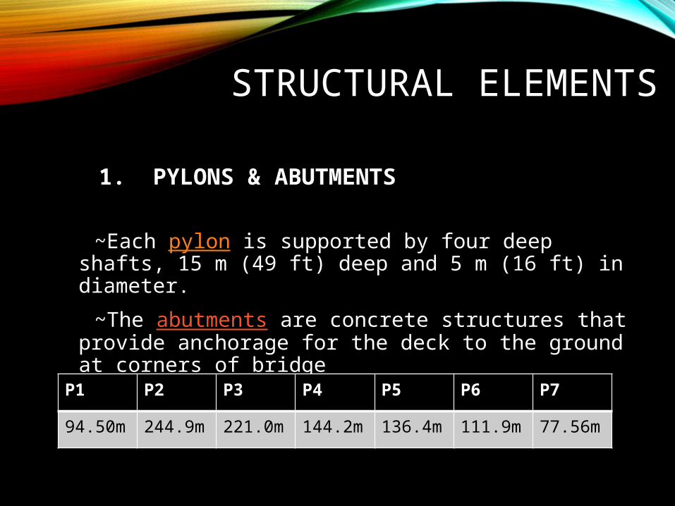
1. PYLONS & ABUTMENTS
~Each pylon is supported by four deep shafts, 15 m (49 ft) deep and 5 m (16 ft) in diameter.
~The abutments are concrete structures that provide anchorage for the deck to the ground at corners of bridge
P1 P2 P3 P4 P5 P6 P7
94.50m 244.9m 221.0m 144.2m 136.4m 111.9m 77.56m


2. DECK• The metallic deck, which appears very light despite its total
mass of around 36,000 tonnes (40,000 short tons), is 2,460 m (8,070 ft) long and 32 m (105 ft) wide.
• These are composed of 173 central box beams, the spinal column of the construction, onto which the lateral floors and the lateral box beams were welded.
• The central box beams have a 4 m (13 ft) cross-section and a length of 15–22 m (49–72 ft) for a total weight of 90 metric tons (99 short tons). The deck has an inverse Airfoil shape, providing negative lift in strong wind conditions.

3. MASTS
• The seven masts, each 87 m (285 ft) high and weighing around 700 tonnes (690 long tons; 770 short tons), are set on top of the pylons. Between each of them, eleven stays (metal cables) are anchored, providing support for the road deck.

4.STAYS • Each mast of the viaduct is equipped with a monoaxial layer of
eleven pairs of stays laid face to face. Depending on their length, the stays were made of 55 to 91 high tensile steel cables, or strands, themselves formed of seven strands of steel (a central strand with six intertwined strands).
• Each strand has triple protection against corrosion (galvanisation, a coating of petroleum wax and an extruded polyethylene sheath). The exterior envelope of the stays is itself coated along its entire length with a double helical weatherstrip. The idea is to avoid running water which, in high winds, could cause vibration in the stays and compromise the stability of the viaduct.
• The stays were installed by the Freyssinet company.

5. SURFACE• To allow for deformations of the metal deck under traffic, a special
surface of modified bitumen was installed by research teams from Appia.
• The surface is somewhat flexible to adapt to deformations in the steel deck without cracking, but it must nevertheless have sufficient strength to withstand motorway conditions (fatigue, density, texture, adherence, anti-rutting etc.).
• The "ideal formula" was found only after two years of research

6. ELECTRICAL INSTALLATIONS
• The electrical installations of the viaduct are large in proportion to the size of the bridge.
• There are 30 km (19 mi) of high-current cables, 20 km (12 mi) of fibre optics, 10 km (6.2 mi) of low-current cables and 357 telephone sockets allowing maintenance teams to communicate with each other and with the command post.
• These are situated on the deck, on the pylons and on the masts.

7. SAFETY MEASURES• The pylons, deck, masts and stays are equipped with a multitude of
sensors. These are designed to detect the slightest movement in the viaduct and measure its resistance to wear-and-tear over time. Anemometers, accelerometers, inclinometers, temperature sensors are all used for the instrumentation network.
• Twelve fibre optic extensometers were installed in the base of pylon P2. Being the tallest of all, it is therefore under the most intense stress. These sensors detect movements on the order of a micrometre. Other extensometers—electrical this time—are distributed on top of P2 and P7. This apparatus is capable of taking up to 100 readings per second. In high winds, they continuously monitor the reactions of the viaduct to extreme conditions. Accelerometers placed strategically on the deck monitor the oscillations that can affect the metal structure. Displacements of the deck on the abutment level are measured to the nearest millimetre. The stays are also instrumented, and their ageing meticulously analysed. Additionally, two piezoelectric sensors gather traffic data: weight of vehicles, average speed, density of the flow of traffic, etc. This system can distinguish between fourteen different types of vehicle.
• The data is transmitted by an Ethernet network to a computer in the IT room at the management building situated near the toll plaza.

CONSTRUCTION OVERVIEW
• Temporary piers used to help launch and support the deck as the the pylons were constructed.
• The 2460m deck was launched in two pieces.
• Pylons and cables were added on top of the piers.

DECK LAUNCHING
• 7 temporary piers help support the weight of the deck.
• 2 deck segments are launched from the each end of te bhridge.
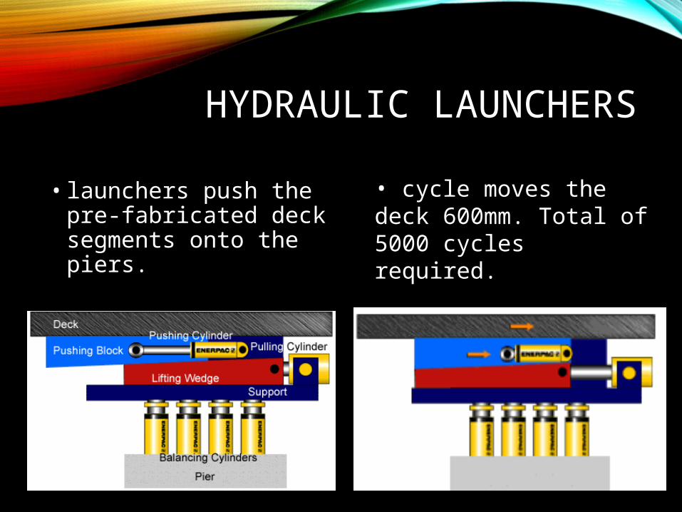
HYDRAULIC LAUNCHERS
• launchers push the pre-fabricated deck segments onto the piers.
• cycle moves the deck 600mm. Total of 5000 cycles required.
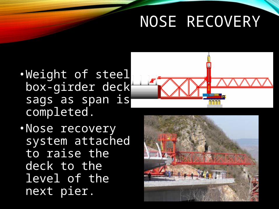
NOSE RECOVERY
•Weight of steel box-girder deck sags as span is completed.• Nose recovery system attached to raise the deck to the level of the next pier.

COMPLETION
• Deck segments move towards each other at the rate of 0.9 meter per hour.
• Two deck segments joined in May of 2004.

PHOTOES OF CONSTRUCTION
Hollow pier construction by moving formwork with hydraulic crane


