The Nelson River Drainage Basin Craig Christensen Julie Nitsche Olsen Astrid Mathilda Arvidson.
THE MATHILDA DRIVER,
A SOFTWARE TOOL FOR HARDWARE TESTING.
by
Eric Kressel
Ib Holm S~rensen
DAIMI MD-18
October 1975.
Institute of Mathematics University of Aarhus
DEPARTMENT OF COMPUTER SCIENCE Ny Munkegade • 8000 Aarhus C • Denmark
Phone 06·128355

1.
PREFACE
Sometimes it is easy to get the impression that testing the hard
ware of a computer is the task of an engineer in electronics and
no one else. This is not the case, however.
To encircle an error in a certain part of the machine, the engineer
requires various bit patterns to loop through the erroneous part with
out effecting too many surrounding sediorsof the hardware. This
usually impl ies writing compl icated programs in a restricted set of
the machine code (in order. to avoid using critical sections surroun
ding the part in error). This is a job for software people, not tech
nicians.
In the spring of 1975, the authors were to assist in the hardware
testing of Mathilda, a computer designed and built in the department
[1].
At this time, RIKKE-1 (a prototype machine of Mathilda, but with
a 16-bit word length) was in operation with an Operating System
written in BCPL [2J running on it. The I/o interface between Mathil
da and RIKKE-1 is extremely simple (a question of connecting them
with 2 cables} and our first task was to adjust the RIKKE-1 operating
system so it viewed Mathilda as a device. We were now able to ex
ploit the power of a higher level language for generating data and
control information to Mathilda. This possibility lead to the develop
ment of a software tool on RIKKE-1 to enable that the data generation
to and the flow of control of hardware test programs in Mathil da coul d be
entirely driven in an interactive fashion from RIKKE-1's console,
given that the test programs were structured suitably.
This approach to the testing of the hardware gave us many advantages,
for example:
• the micro code in Mathilda was short, simple to write and
used very few parts of the machine other than those of in
terest.
• the interactive way of working gave us immediate response,
and closing in sources of errors was more or less trivial.
2.
This manual describes the facilities of this software tool which we
have named the Mathilda Driver, and gives a list of the commands
applicable to it. We cannot describe how to hardware test Mathil-
da, because each test program has its own properties and they are
defined by the resource to be tested and through discussions between
programmers and techni cia ns on the spot. We hope, however, that
the Mathilda Driver is a tool so flexible that any test problem, no
matter how intricate, can be solved by using the facil ities provided
in the Driver in such a way that the test program in Mathilda may
be written in a very simple-minded fashion.
We assume the reader has read the references [1 J and [2J.

Tab I e of Contents
O. INTRODUCTION
1. MODE OF OPERATION
2. COMMAND STRUCTURE
3. CONTROL AND DATA GENERATION FEATURES
Description of various Buffers
Patterns
Bits
Masks
Comparison
Shifts
Micro Instruction Generation
ALU
Display
Loading Microprograms from RIKKE-1
4. TABLE OF SINGLE COMMANDS in alphabetic order
5. TECHNICAL DETAILS
6. CROSS REFERENCE INDEX
3.
page
4
4
4
5
8
15
16
Appendix A.
Appendix B.
Appendix C.
TheBootstrap Normalizer for Mathilda 18
The Read and Write Routines for Test Programs 20
An Example of a Test Program and the 21
Command Strings Used on it.
4.
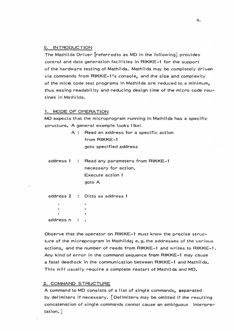
o. INTRODUCTION
The Mathilda Driver [referred to as MD in the following] provides
control and data generation facit ities in RIKKE-l for the support
of the hardware testing of Mathilda. Mathilda m~y be completely driven
via commands from RIKKE-l's console, and the size and complexity
of the miclO code test programs in Mathilda are reduced to a minimum,
thus easing readabil ity and reducing design time of the micro code rou
tines in Mathi Ida.
1. MODE OF OPERATION
MD expects that the microprogram running in Mathilda has a specific
structure. A general example looks I ike:
address 1
address 2
address n
A: Read an address for a specific action
from RIKKE-l
goto specified address
Read any parameters from RIKKE-l
necessary for action.
Execute action
goto ·A
Ditto as address 1
Observe that the operator on RIKKE-l must know the precise struc
ture of the microprogram in Mathil da; e. g. the addresses of the various
actions, and the number of reads from RIKKE-l and writes to RIKKE-l.
Any kind of error in the command sequence from RIKKE-l may cause
a fatal deadlock in the communication between RIKKE-l and Mathilda.
This will usually require a complete restart of Mathilda and MD.
·2. COMMAND STRUCTURE
A command to MD consists of a I ist of singl e commands, separated
by del imiters if necessary. [Del imiters may be omitted if the resulting
concatenation of single commands cannot cause an ambiguous interpre
tation. ]

5.
A single command consists of a letter, a double letter, or one of the
I atter followed by an integer or a bit pattern or both. An integer is
always interpreted as a decimal integer. A bit pattern is a sequence
of 0 1 sand 11 s. The pattern may be no longer than 16 bits.
A del imiter is inserted in the command string by typing VT on the
keyboard. A 1 $1 is echoed on the console. The command string is
terminated and immediately executed by typing two delimiters in suc
cession.
A single character in the command string may be deleted by typing
RUBOUT. The character is echoed on the console. An incomplete
command string may be deleted entirely by typing CTRLx. The promp
ting '*' is echoed on the console.
MD is equipped with 4 macro buffers. A command string may be in
serted into a macro; the macro may then be executed any number of
times required by the operator. If an error is detected during exe
cution, the operation is terminated. A macro definition may be called
within another macro definition, but recursive definitions, i. e. a
macro call ing itself, are not allowed.
3. CONTROL AND DATA GENERATION FEATURES
MD can manipulate buffers in different ways. A list of the buffers
contained in MD follows:
Output Buffer.
1 buffer, 64 bits wide, primarily used for sending data to Mathilda.
Control Buffer.
1 buffer, 64 bits wide, used for sending control information to Ma
thilda, i. e. pointer and function control. Only the 16 least signifi
cant bits are accessibl e.
Address Buffer.
1 buffer, 64 bits wide, used for sending sequencing information to
Mathilda. Only the 16 least significant bits are accessible.

6.
Add Buffer.
1 buffer, 64 bits wide, used to contain a 64 bit constant which may
be added to the Output Buffer during execution of a command sequence.
The addit ion is performed in groups of 16 bits [63-48, 47-32, 31-16,
15-0]. No carry is taken across the 16 bit bounds.
Input Buffer.
1 buffer, 64 bits wide, used to receive data from Mathilda.
External Register Buffer.
1 buffer, 16 bits wide, used to initialize Mathilda's External Register.
Scratch Buffers.
8 buffers, 64 bits wide, numbered ¢ through 7, used for various pur
poses, e. g. read, write, comparison, etc. The reader will get full
details in the list of single commands.
MD is equipped with the following data generation facilities:
Pattern Generat ion.
Any bit pattern, 0-16 bits wide, may be
1) copied across the 64 bits of the Output Buffer.
2) inserted at any bit position in the Output Buffer.
3) added in at any bit position of the Output Buffer.
B it Manipulation.
Any bit in the Output Buffer may be
1) inserted [the rest of the bits left untouched]
2) set [the rest cleared]
3) reset [the rest left untouched]
Mask Generation.
A mask generator, equivalent to the Post Mask Generator in Ma
thi Ida, is provided to work on the Output Buffer.
Compar i son.
The contents of the Input Buffer may be compared with the Output
Buffer or any of the scratch buffers. Depending on the result of the

7.
comparison, a choice between 2 different command string executions
is made.
Shift.
The contents of the Output Buffer may be shifted cycl ic through 64
bits either left or right. The contents of the External Register and
Control Buffers may be shifted left 0-15 bits (logically) during trans
miss ion to Mathi Ida. The actual contents are, left untouched.
Instruction Generation.
Any micro instruction for Mathilda may be generated with a simple
Micro Assembler included in MD. The operator specifies which field
in the instruction (i. e. f1, sl, etc.) he wishes to initialise followed,
by the code in decimal. The micro instruction is placed in the Out
put Buffer.
64 bit ALU.
MD is equipped with a 64 bit ALU, equivalent to the hardwired ALU
in Mathilda. It contains the same functions and operates in the same
fashion. A-input is always the Output Buffer, B-input may be any of the
Scratch Buffers, and the result is delivered in Scratch Buffer ¢. The
function of the ALU is specified in a separate command.
Display.
The contents of any buffer can be displayed either on the console or on
the pr inter.
Load.
MD can read binary paper tape micro programs generated by MARIA
in bootstrap loader format [i. e. default format], and transform them
to something readable for Mathilda. A special micro program, called the
Bootstrap-Normal izer, has been written to enabl,e the loading of such
programs from MD. This impl ies that test programs need not be con
fined to 16 words, but can use as many control store words as neces
sary. See appendix A for the source text of the Bootstrap-Normal izer.

8.
4. S INGLE COMMANDS
The following is I ist of the single commands provided in MD, with
a short description of each.
a=<n>
al = <n>
Load Address Buffer with <n>.
Load ALU function selector with <n>.
Any activation of the ALU in MD ,follo
wing this command will give the result
of the specified function. Possible func
tions are:
o A. 1 A V B 2 AV,B 3 -1 4 A + (A /\, B) 5 (A V B) + ( A/\ -, B) 6 A+-,B 7 (A - B) -1 8 A + (A /\ B) 9 A+ B
10 (A V ,B) + (A /\ B) 11 (A /\ B) -1 12 A+ A 13 (A V B) + A 14 (A V, B) + A 15 A - 1 16 -, A 17 ,(A V B) 18 ,A /\ B 19 0 20 -, (A /\ B) 21 ,B 22 A NEQV B 23 A /\ -, B 24 -, A V B 25 AEQVB 26 B 27 A /\ B 28 All I j IS
29 A V -, B 30 A V B 31 A 32 33 34 35 36 37 38 39

ac
al <n>
bc <n>
bi <n>
bs <n>
c=<n>
c+
c-
cp<str1 > /<str2>
cp<n> <str1 > /<str2>
da
db
dc
de
di
dj
40 41 42 43 44 45 46 47
As functions
o - 15, plus 1,
e. g. 32: A + 1
39: A - B
9.
Load ALU function selector from Con
trol Buffer's 16 least significant bits.
Activate ALU with function given in ALU
function selector. A- input is Output
Buffer and B-input is Scratch Buffer
<n>. Result is delivered in Scratch
Buffer cp. Clear bit <n> in Output Buffer. All other
b its left untouched.
Insert bit <n> [set bit <n> ] in Output
Buffer. All other bits left untouched.
Set bit <n> in Output Buffer. All other
bits are cleared.
Load Control Buffer with <n>.
Increment Control Buffer.
Decrement Control Buffer.
Compare Input Buffer with Output Buffer.
If buffers are logically equivalent, exe
cute command string <str1>,otherwise
execute command string <str2>. Note:
<str2> must D.2! contain
any del imiters.
As command above, where Output Buffer
is exchanged with Scratch Buffer <n>.
Display Address Buffer on printer.
Display Output Buffer and Input Buffer,
in that order, on printer.
Display Control Buffer on printer.
Display External Register Buffer on
printer.
Display Input Buffer on Printer.
Display Control Buffer an.d Input Buffer,
in that order, on printer.

do
du
d<n>
e = <n>
e+
e-
f
h
Display Output Buffer on printer.
Display ALU function selector on
printer.
10.
Display Scratch Buffer <n> on printer.
Load External Register Buffer with <n>o
Increment External Register Buffer.
Decrement External Register Buffer.
Give form feed on printer.
Terminate execution of current command
string.
i <fieldl> ••• <fieldn>$ Create micro instruction in Output Buffer.
<fieldk> contains field description and
value to be inserted in field, and must
have the following format:
m<n>
<fd> = <m>$
<fd> may be wr itten as:
fl f3 vs bi (bisb)
s 1 s3
m2 m4
f2 f4
m3 as
ds ci (cisb)
be (enable) sc
bd af
bs at
The field specified by <fd> is then set
to the value <m>. <m> is masked to suit
the bit width of the field.
Load Mathi Ida with contents of binary
paper tape in RIKKE-l's reader. Paper
tape must be in Bootstrap Loader format
from MARIA, i. e. default format. MD
then transmits to Mathi Ida:
1) Load address in Control Store
2) Count of i nstructions-l
3) Instructions
4) Execution start address
Note: Contents of Address Buffer,
and Output Buffer are undefined after
execution of 'JI instruction.
Generate <n> l's in Output Buffer.

mc
oe
of
on<n>
o
11
11.
<n> 2:. 0, generate <n> O's, starting
at most significant bit, set
rest of bits to 1.
<n> > 63, generate 128 - <n> O's,
starting at least signifi
c;ant bit, set rest of bits ,
to 1.
Generate mask as above, but take contro.1
information from Control Buffer's 16
least significant bits.
Punch approximately 15 cm paper feed
[i. e. blank tape, no feed holes] on pun
cher.
Punch 8 frames with feedholes (no data]
on puncher.
Punch the integer <n> as 2 frames on
puncher; the 8 most significant bits first
followed by the 8 least significant btis.
Punch Output Buffer on puncher. The bits
of the buffer appear on the paper tape as
follows:
frameno. tape bitno.
1 15-8
2 7-0
3 31-24
4 23-16
5 47-40
6 39-32
7 63-56
8 55-48
[This format is equivalent to various mi
croloaders format for RIKKE-1 and Ma
thi Ida].

o<n>
oa
pc<p>
ps<n>, <p>
P i<l1>, <p>
pm
pm<n>
pb
pb<n>
pa
pa<n>
q
r
r<n>
rs
12.
Punch Scratch Buffer <n> [as aboveJ.
Punch 8 Scratch Buffers in the same
format as above on puncher, starting
with Scratch Buffer ¢ and ending with
Scratch Buffer 7.
Copy pattern <p> across Output Buffer.
<p> may be any combination of bits and
of length between 1 and 16 bits. <p> is
then repeated as many times in the Out
put Buffer as there is room for it.
Set pattern <p> in Output Buffer star
ting at bit position <n>o All other bits
are cleared.
Insert pattern <p> in Output Buffer,
starting at bit position <n>o All other
bits are left untouched.
Move pattern in Output Buffer to Add
Buffer.
Move pattern in Output Buffer to Scratch
Buffer <n>o
Move pattern in Add Buffer back to Out
put Buffer.
Move pattern in Scratch Buffer <n> back
to Output Buffer.
Add Add Buffer to Output Buffer. The
adding is performed in 16 bit groups
[63-48, 47-32, 31-16, 15-0J and no
carry is transported between the groups.
Add Scratch Buffer <n> to Output Buffer.
Terminate MD session and return to ope
ting system.
Read from Mathilda into Input Buffer.
Read from Mathilda into Scratch Buffer <n>o
Reset Input Flag in RIKKE-1 for Mathilda.
This instruction must be used with care.
If the Input Flag is reset already, an
input deadlock wi II occur.
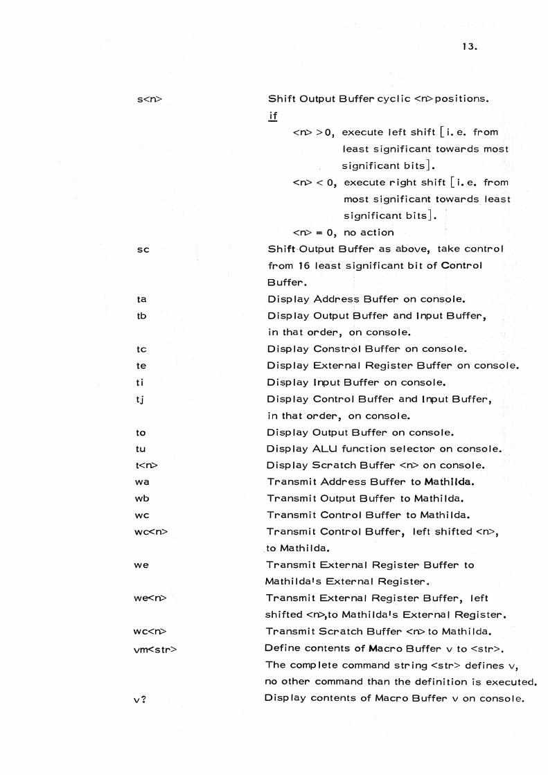
s<n>
sc
ta
tb
tc
te
t i
tj
to
tu
t<n>
wa
wb
wc
wc<n>
we
we<n>
wC<n>
vm<str>
v?
13.
Shift Output Buffer cycl ic <n> positions.
if
<n> >0, execute left shift [i.e. from
least significant towards most
significant bitsJ.
<n> < 0, execute right shift [i. e. from
most significant towards least
significant bitsJ.
<n> = 0, no action
Shift Output Buffer as above, take control
from 16 least significant bit of Control
Buffer.
Disp lay Address Buffer on console.
Display Output Buffer and Input Buffer,
in tha t order, on console.
Display Constrol Buffer on console.
Display External Register Buffer on console.
Display Input Buffer on console.
Display Control Buffer and Input Buffer,
in that order, on console.
Display Output Buffer on console.
Display ALU function selector on console.
Display Scratch Buffer <n> on console.
Transmit Address Buffer to Mathilda.
Transmit Output Buffer to Mathi Ida.
Transmit Control Buffer to Mathilda.
Transmit Control Buffer, left shifted <n>,
.to Mathilda.
Transmit External Register Buffer to
Mathi Ida's External Register.
Transmit External Register Buffer, left
shifted <n>,to Mathilda's External Register.
Transmit Scratch Buffer <n> to Mathilda.
Define contents of Macro Buffer v to <str>.
The complete command string <str> defines v,
no other command than the definition is executed.
Display contents of Macro Buffer v on console.
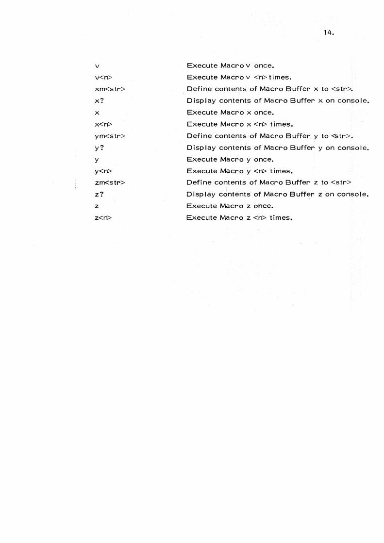
v
v<n>
xm<str>
x?
x
x<n>
ym<str>
y?
y
y<n>
zm<str>
z?
z
z<n>
Execute Macro v once.
Execute Macro v <n> times.
14.
Define contents of Macro Buffer x to <str>.
Display contents of Macro Buffer x on console.
Execute Macro x once.
Execute Macro x <n> times.
Define contents of Macro Buffer y to <str>.
Display contents of Macro Buffer y on console.
Execute Macro yonce.
Execute Macro y <n> times.
Define contents of Macro Buffer z to <str>
D i sp I ay contents of Macro Buffer z on conso Ie.
Execute Macro z once.
Execute Macro z <n> times.

15.
5. TECHNICAL DETAILS
The Input Port B of Mathilda is connected to Output Port B, device
11 on RIKKE-1 in such a way that the 16 bits transmitted from RIK
KE-1 are input in the Input Port's least significant bits. This means
that the micro coded Read routine in Mathilda must read 4 times and
shift and logically OR the results together to comprise a full 64 bit
Mathilda data word. The current Standard Read Routine in Mathilda
does this and expects RIKKE-1 to send the 64 bit word in descending
bit order, i. e. first bits 63-48, .!.b.£!J. bits 47-32 etc. MD's transmit
routine is devised to do this. See appendix B.
The Output Port B of Mathilda is connected to the Input Port B, device
11, on RIKKE-1. As in the input case, only 16 least significant bits
may be transmitted. The current Write routine in Mathilda transmits
a 64 bit word in descending bit order, and MD's read routine is devised
to accept this. See appendix B.
The External Register of Mathilda is connected to Output Port B, de
vice 8, on RIKKE-1. When MD transmits to the External Register
Buffer, it sends the contents out on this I ine. There is no flag com
munication on this I ine, so logically speaking, Mathi Ida's External
Register is currently equivalent to RIKKE-1' s Output Port B device
buffer 8.
MD is not in the RIKKE-1 operating system's resident I ibrary, but
must be loaded and run as a user program.
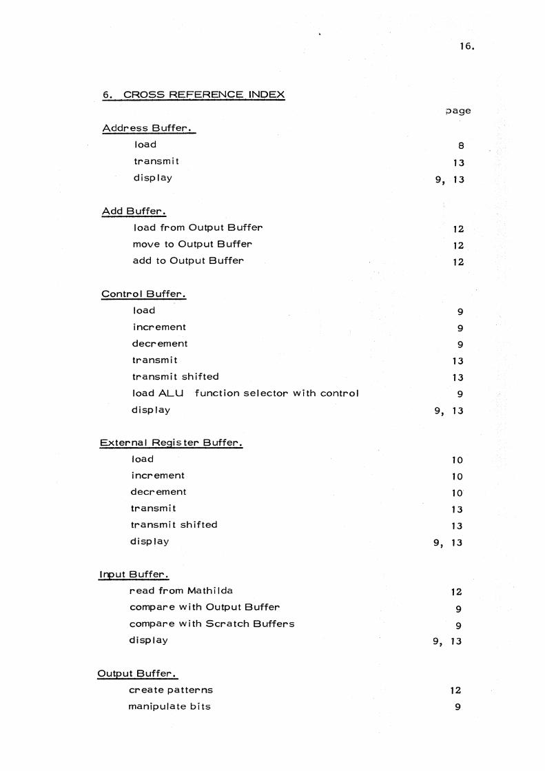
6. CROSS REFERENCE INDEX
Address Buffer.
load
transmit
disp lay
Add Buffer.
load from Output Buffer
move to Output Buffer
add to Output Buffer
Contro I Buffer.
load
increment
decrement
transmit
transmit sh if ted
load ALU function selector with control
display
External Register Buffer.
load
increment
decrement
transmit
transmit shifted
display
Input Buffer.
read from Mathilda
compare with Output Buffer
compare with Scratch Buffers
display
Output Buffer.
create patterns
manipulate bits
16.
;:>age
8
13
9, 13
12
12
12
9
9
9
13
13
9
9, 13
10
10
10
13
13
9, 13
12
9
9
9, 13
12
9
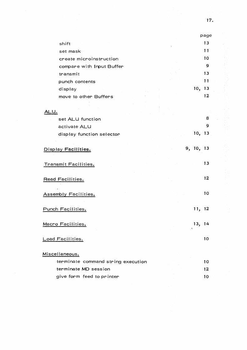
ALU.
shift
set mask
create microinstruction
compare with Input Buffer
transmit
punch contents
display
move to other Buffers
set ALU function
activate ALU
disp lay function sel ector
Display Facilities.
Transmit Facilities.
Read Facilities.
Assembly Facilities.
Punch Faci I ities.
Macro Facilities.
Load Facilities.
Miscellaneous.
terminate command string execution
terminate MD session
give form feed to printer
17.
page
13
1 1
10
9
13
11
1O, 13
12
8
9
10, 13
9, 10, 13
13
12
10
11, 12
13, 14
10
10
12
10

18.
Appendix A.
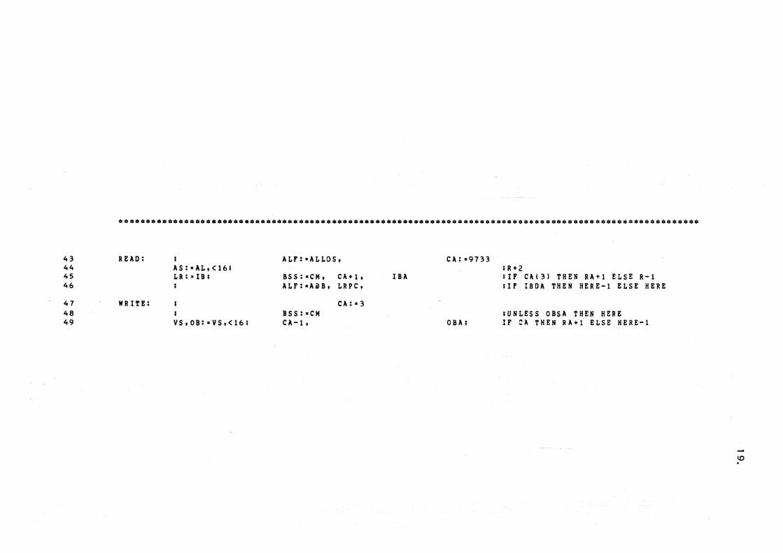
43 REAO: ALF: -ALLOS, CA:-9733 44 AS:-AL,(16; ;R+2 45 LR:",lB; BSS:-CM, CA+I, IBA ;IF C A ( 3) THEN RA+I ELSE R-I 46 I ALF:-AilB, LRPC, ; I F IBDA THE N HERE-l ELSE HERE
47 WRITE: CA:-3 48 BSS:aCM ;UNLESS OBSA THEN HERE 49 YS,OB: .. YS,(16; CA-l, OBA; IF :::-A. THEN RA+l ELSE HERE-l
\0 .

20.
Appendix B.

LINENO 0:
***. 1 : 2 : 3: 4: 5 : 6: 7: 8 : 9: 10: 11: 12 : 13: 14 : 15 :
*0:101:0
16: 17: 18: 19 : 20: 21 : 22: 23: 24: 25: 26: 27: 28: 29: 30: 31: 32:
M~RI~ VERSION MATHILDA - 4.1 25/07175 13.23.48.
CS ADDRESS
BOOTSTRAPLOADER AND NORMALIZER FOR MATHILDA
AT EX IT WE HAVE MAIOI • LAIOI • LBIOI • PAIOI • NOMASK MAl11 • PAl11 • PBIOI • FULLMASK MAP - LAP • PAP • PBP • 0 LRP • 0 BSS • PGS • CM RAP' RBP - 0 WAP AND WBP ARE UNCOUPLED SCUALF IS SET TO A+B KC AND KD ARE CLEARED .
••••••••••••••••••••••••••••••••••••••••••••••••••••••••••••••••••••••••••••••••••••••••••••••••••••••••••
0 I ALF:- ALLOS, PABC, LBPC 1 ALL1S1 MAPC, PAl-BUS, LAPC 2 MA:-ALL1S; LB:-SB, SCUALF+, LA:-S8 3 ALI MAP+1, RAPC, PB:-BUS, PAP+1 4 MA:-ALI IBA, RA! , PA:'BUS, R-READ 5 ALI SA:·SB, RA! R-REAO 6 AL; CB:-SB, RA! , PGS :,.CM, R+READ. 7 ALI RB! , OC:'BUS, KDC 8 CSLOAD, SL 9 RA! , R+REAO. 10 I CB-1, KCC, SA+1 UNLESS CB THEN RB. 11 ALI RBPC, SA:-SB SA 12 READ: I ALF: - ALLOS, CA:-9733 13 AS:'AL,<16; PAPC, MAPC R+2 14 LR:'IBI BSS:'CM, CA+1, UNCPLB, IBA IlF CII ( 31 THEN RA+1 ELSE HERE-1 15 ALF:· AilB, LRPC, UN C P LA ; IF !BOA THEN HERE-1 ELSE HERE
tv 0 OJ .

21.
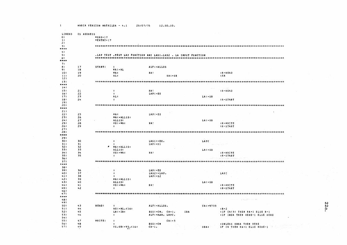
Appendix C.
The test program given in this example tests the Loading Mask A re
gister group) LA. The LA mask) specified by the LA pointer) LAP,
is active when Working Register A, WA, is loaded from the shifted
bus.
The mask works as follows:
If bit i of the LA mask is 1 then
bit i of WA is bit i of the shifted bus.
If bit i of the LA mask is 0 then
bit i of WA is left unchanged.
We wi II now discuss the commands needed to test the LA mask register
group.
First of all, the Bootstrap-Normal izer microprogram must be dead
started into Mathilda.
Mathilda is ready to be loaded with the test program. The program
is set into RIKKE-1' s reader and the command
1$$
is typed on the console. Mathilda loads the program into it's control
store.
We are now interested in testing that the LAP pointer functions. This
is accomplished by filling a count in each register of the group while ad
justing the pointer, i. e. if LAP = 6, we fi II 6 into the register pointed
to by LAP. When we read the registers again we can check if this really
happened. As the physical register is built of 8 bit modules each having
their own pointer connection we wish to check that the pointer is cor
rect for all 8 bit modules so we want a count in 8-bit groups. We do
this by using the Add Buffer. We write:
pcOOOOOOO 1 $ pm$ $
This command sets 1 bit in each 8 bit group of the Output Buffer and
puts it in the Add Buffer as well. We define the macro that is to ini
tialise 1 register:
xm a = 21 $ we 12 $ wa $ wb $ $
(Please read the listing of the program while studying this macro).

22.
Why Iwe12"? Because when LAP loads it's input from the External
Register, it takes bits 15-12. The good hardware tester should al
ways have these pecul iar iti es in mind, and look them up every time -
never trust your memory.
We define a macro that loads a register and increments the Output
Buffer and the External Register.
ym x $ pa $ e + $ $
We are ready to load the masks. We write:
e = 0 $$ y 16 $$
The LA registers are now initialised with the count, and we define
a macro to read them and then we execute it.
zm a = 25 $ we12 $ wa $ r $ di $ e + $ $
e = 0 $$
z 16 $$
The output from the printer is analyzed to detect any errors.
We encourage the reader to visual i ze the rest of the test process -
or even try it!
I.INENO 0: 1 : 2 : 3 :
*0 ••
4 : 5 : 6':
0 •••
7 : 8 : 9: 10: II : 12 : 13:
.0*. 14 : 15: 1.6 : 17: 18 : 19: 20:
* •• 0
21 : 22: 23: 24: 25: 26: 27: 28 :
*.0. '29: 30: 31 : 32: 33: 34: 35: 36: 37:
38: 39: 40: 41 : 42: 43: 44: 45: 46: 47:
•••• 48: 49: 50: 51 : 52: 53: 54: 55: 56: 57:
HARIA YERSION HATHII.DA - 4.1 25/07175 12.50. 10.
CS AOORESS
17 18 19 20
21 22 23 24
25 26 27 28 29
30 31 32 33 34 35
36 37 38 39 40 41 42
43 44 45 46
47 48 49
·ORG-17 ·ENTRro!7
.I.AP TEST ,TEST I.AP FUNCTION ANO I.ASI,I.AS2 • I.A INPUT FUNCTION ••••••••••••••••••••••••••••••••••••••••••••••••• 0 •••••••••••••••••••••••••••• _ ••••••••••••••••••••••• _ •••
SURT:
•
REAO:
WRITE:
; WA:-AI. WA; AI.;
; A I.;
\II A ; WA:-ALI.IS; ALLIS; YS:-U;
WA:-ALLIS; ALLIS; YS:-WA;
;
WA:'ALLIS; ALLIS; YS:,WAI
AS:-AL,(16; LR:-lB;
YS.OB: -YS.(16;
AI.F:-AI.I.OS
RA!
RA! I.AP: -EX
LAP:-EX
RA!
LASI!-EX, LAP:-SI
RA!
LAP:-U LAS2:-LAP, LAP:-S2
RA!
SA:-S8
Hr: -ALLOS,
BSS:'CM, CA+I, ALr:-AilB, LR PC,
C A: - 3 BSS:-CM CA-l.
I. A: - S 8
LA:-S8
LAPC
LA:-S8
LA:-S8
CA:"9733
IBA
OUI
IR -R H 0 ; SA
; R-SURT
IR-WRITE IR-SaRT
;R-WRITE ;R-saRT
LAP:
IR-HITE ;R-STHT
; R +2 ; IF C A ( 3) ; I F IBOA
THU THEN
RA+I ELSE R-I HERE-l ELSE HERE
;UNLESS OBSA THEN HERE H CA THEN RA+I ELSE HERE-I
tv tv OJ

REFERENCES
[ 1 J P. Kornerup, Bruce D. Shr iver:
A Description of the MATHILDA Processor
DAIMI PB-52, Department of Computer Science,
University of Aarhus, Denmark, july 1975.
[2J Er ic Kressel, Ib Holm S¢rensen:
The first BCPL System on RIKKE-1
DAIMI MD-17, Department of Computer Science,
University of Aarhus, Denmark, july 1975.
23.

Micro Archives 5-l~
The Mathilda driver: a software tool for hardware testing
Kressel, Eric. The Mathilda driver: a software tool for
hardware testing / by Eric Kressel and Ib Holm S~rensen.-- Aarhus, Denmark: Department of Computer Science, Institute of Mathematics, University of Aarhus, 1975.
(DAIMI; MD-1S)
I. Joint author. II. Title.