The latest news from REDWatch — REDWatch - Redfern ...
124
Transcript of The latest news from REDWatch — REDWatch - Redfern ...

ManningP
Typewritten Text
Document 7

Table of Contents
1. Preliminary Service Recommendations
2. Requirements for vertical circulation under peak AM loads
3. Pedestrian Evacuation and Fire engineering report
4. STEPS Pedestrian Simulation Modelling results
5. Structural Design Report
6. Scope for OHW traction Option - C
7. Signalling Concept Option - C


Preliminary Services Recommendations Redfern Station Upgrade Jackson Teece Architects 15 March 2007 Reference 23443/3.8 Revision 03
Connell Wagner Pty Ltd ABN 54 005 139 873 116 Military Road Neutral Bay New South Wales 2089 Australia Telephone: +61 2 9465 5599 Facsimile: +61 2 9465 5598 Email: [email protected] www.conwag.com

Document Control
Document ID: I:\23443\ENG\REPORTS\SERVICES\23443 SERVICES ADVICE LANDSCAPE.DOC
Rev No Date Revision Details Typist Author Verifier Approver
00 12 December 2006 Preliminary Issue ACT ACT
01 20 December 2006 Issue For Review - Mechanical services not yet revised. ACT ACT
02 21 December 2006 Issue For Review ACT ACT
03 15 March 2007 Issue For Approval ACT ACT
A person using Connell Wagner documents or data accepts the risk of: a) Using the documents or data in electronic form without requesting and checking them for accuracy against the original hard copy version. b) Using the documents or data for any purpose not agreed to in writing by Connell Wagner.

Redfern Station Upgrade Jackson Teece Architects Preliminary Services Recommendations
⏐ REVISION 03 ⏐ PAGE i
Contents
1. Executive Summary 1
2. Station Upgrade 2 2.1 Electrical services 2 2.2 Fire Services 3 2.3 Hydraulic Services 3 2.4 Vertical Transportation 4 2.5 Mechanical services 4
3. Tower Development 5 3.1 Electrical Services 5 3.2 Fire Services 6 3.3 Hydraulic Services 7 3.4 Vertical Transportation 9 3.5 Mechanical Services 9
Redfern Station Upgrade Jackson Teece Architects Preliminary Services Recommendations
⏐ REVISION 03 ⏐ PAGE 1
1. Executive Summary This report has been prepared by Connell Wagner at the request of Jackson Teece to provide preliminary advice regarding anticipated services requirements for the Option C upgrade of Redfern Station and construction of a Grade A commercial tower with associated retail spaces. The site is wholly owned by Railcorp although the design is to be flexible to allow development to occur adjacent to the Station. This report has been prepared without the benefit of a site inspection to assess existing conditions and addresses requirements within the project boundary. The impact on lot boundaries, connections to infrastructure etc, will need to be addressed when the project is more clearly defined to determine whether easements are required to be created for services. The following summarises the conclusions and recommendations of the report: • Electrical services
– Existing station substations have insufficient capacity for reuse and insufficient space for upgrade. New substations are required.
– Separate substations for the station and the adjacent development are recommended unless Railcorp wish to act as the energy retailer for tenants.
• Fire services – A fire safety engineer should advise the scope of upgrade for Platforms
11/12 (ESR). – Fire services recommended for the station upgrade are in accordance
with the BCA and Railcorp requirements. – Fire services recommended for the tower development are in accordance
with the BCA. • Hydraulic services
– Sewerage pumping will be required to service platforms 11/12. – Hydraulic services recommended for the tower development are in
accordance with the BCA.
• Mechanical
– Minimal air conditioning and ventilation are proposed for the station upgrade.
– Plant space for common central plant will require one floor of the tower development.
– Mechanical services recommended for the tower development are in accordance with the BCA.
• Vertical transportation – Lifts and escalators proposed for the station upgrade are typical for
Railcorp stations. – Preliminary estimates are that eight (8) lifts (not six) will be required for
the tower development to satisfy PCA Grade A service.

Redfern Station Upgrade Jackson Teece Architects Preliminary Services Recommendations
⏐ REVISION 03 ⏐ PAGE 2
2. Station Upgrade 2.1 Electrical services 2.1.1 Existing infrastructure The existing Railcorp infrastructure consists of two 500kVA substations which are intended to operate in a mutual redundancy arrangement, ie each is intended to operate at less than 50% capacity so that in the event of a supply failure on one, the other can support the full load of the station. Based on information provided by Railcorp, the existing substations are loaded at 84% and 46% of design capacity (which is 50% of rated capacity) and will not be able to support the additional load of proposed lifts and escalators. Railcorp advice is that there is insufficient space for the existing transformers to be upgraded. 2.1.2 Railcorp systems The existing communications, signalling and electrical systems are located at a mezzanine level above the Illawarra Relief Platforms and at platform level of the Illawarra Relief. These may need to be re-established within the new concourse area. Electrical loads for these areas usually increase during redevelopment due to increases in electronic equipment loads and air conditioning loads. 2.1.3 Proposed infrastructure The lighting and power services for the station, including ticketing, administration, platform and concourse areas, will be supplied from the Railcorp substations. Power will also be provided to new lifts and escalators. The options available for providing additional electrical services capacity are detailed in the table below.
Option Comment
Option 1 - Provide one additional 500 kVA substation
This option would require significant modification of existing switchboards, provision of complicated interconnections and other means of splitting the load of three substations across two substations in the event that one was removed from service for any reason.
Option 2 - Provide two new 500 kVA substations
This option would involve transfer of some load to two new low voltage switchboards whilst retaining the existing substations which are assumed to be well into their rated service life.
Option 3 - Provide two new 750 kVA substations
This option would involve establishment of two new substations, transfer of existing loads to the new substations and removal of the existing substations.
Option 3 is recommended because: • it provides a system that satisfies the intent of the standard design preferred by
Railcorp • it provides a new installation complete with defect liability and warranties • it provides the simplest system to manage and maintain • it provides a system configuration that would be familiar to Railcorp staff

Redfern Station Upgrade Jackson Teece Architects Preliminary Services Recommendations
⏐ REVISION 03 ⏐ PAGE 3
2.1.4 Spatial Requirements The following are reasonable spatial allowances for substations and main switchrooms for Railcorp infrastructure based on other recent station redevelopments.
Item Dimensions (LxWxH)*
Comments
Substation 1 6000 x 4000 x 3600 One egress door and one double equipment door set. All open outwards.
Railcorp Main Switchroom 1 5000 x 4000 x 3600 One egress door and one double equipment door set. All open outwards.
Substation 2 6000 x 4000 x 3600 One egress door and one double equipment door set. All open outwards.
Railcorp Main Switchroom 2 5000 x 4000 x 3600 One egress door and one double equipment door set. All open outwards.
* all dimensions are clear dimensions without intrusions. To comply with AS3000 each main substation and main switchroom must be located within one floor of ground level. 2.2 Fire Services Fire services for the station are proposed to be limited to smoke detection in specific areas and portable extinguishers located as required by the BCA or other applicable standard. 2.3 Hydraulic Services 2.3.1 Generally It is envisaged that public toilet facilities as well as facilities for station staff will be located at concourse level. It is likely that a toilet will be required on platforms 11/12 which will require pumping of sewerage.
2.3.2 Sanitary Drainage Sanitary Drainage for Public Toilets and Station Staff will be by means of an independent connection to the water authority’s sewer. It is envisaged that the areas can be drained by means of gravity and no pumping will be required. This system will be designed in compliance with AS3500.2.2, New South Wales Code of Practice Plumbing and Drainage and Sydney Water Corporation Ltd requirements. 2.3.3 Stormwater Drainage and Downpipes Downpipes should be provided to convey rainwater safely and without nuisance from the station concourse roof to Sydney City Council stormwater infrastructure. The stormwater system will be designed in compliance with AS3500.3.2.1, Sydney City Council and Sydney Water requirements. 2.3.4 Cold Water Reticulation A Cold Water reticulation system must be provided from the water authority’s infrastructure to a water meter with “property containment (backflow prevention) device” at ground floor level. We would also recommend that a dual, automatically backflushing screen filter of 100 micron screen size, is installed “downstream” of the water meter. From the water meter, water will be reticulated to fixtures requiring potable water throughout the building. The entire cold water system will be designed in full compliance with AS3500.1.2, New South Wales Code of Practice Plumbing and Drainage and Sydney Water Corporation Ltd requirements. 2.3.5 Hot Water Reticulation A hot water reticulation system will be provided for hot water supply to staff toilet areas and tea making facilities. It is envisages that hot water needs for these areas will be provided from a 50 litres commercial type electric hot water unit.

Redfern Station Upgrade Jackson Teece Architects Preliminary Services Recommendations
⏐ REVISION 03 ⏐ PAGE 4
The entire hot water system will be designed in full compliance with AS3500.4.2, New South Wales Code of Practice Plumbing and Drainage and Sydney Water Corporation Ltd requirements. 2.3.6 Fire Hydrant and Fire Hose Reel System A combined Fire Hydrant and Fire Hose Reel reticulation system in accordance with BCA, AS 2419, AS2441 and NSWFB requirements must be provided from the authority’s water main to all locations requiring fire hydrant and fire hose reel coverage, generally at, but not limited to fire exits. A “Fire Brigade Booster Assembly” will be provided at street-level, facilitating pressure boosting and water supply via Fire Brigade appliance. It is envisaged that the mains pressure will be sufficient and therefore no fire pumps will be required. Fire Hydrant/Fire Hose reel cupboards are in the order of 550 x 900mm and usually extends from floor to ceiling. 2.4 Vertical Transportation 2.4.1 General The lifts will be designed be designed to fully comply with all current requirements of the SAA Lift Code, AS 1735, the Building Code of Australia (BCA), OHS 2001 & RailCorp where appropriate. All lifts would be glazed to allow observation of interiors from outside. All lifts would feature facilities for disabled persons & fire brigade operation. All lifts would feature the latest variable voltage, variable frequency & microprocessor control technology. The station lifts car internal finishes & control buttons would be heavy duty/vandal resistant type.
2.4.2 Description • Number of Lifts Six (6) • Type Passenger • Rated Load 1275 kg (17-passenger). • Rated Speed 1.0 m/s. • Machine Type Gearless, machine room less. (MRL) • Drive System Variable Voltage, Variable Frequency (VVVF). • Control System Microprocessor. • Levels Served Concourse to Platform. • Number of Openings 2 on the same side each lift. • Internal Car Dimensions 1450 mm wide x 1950 mm deep. • Liftwell Dimensions 2200 mm wide x 2500 mm deep. • Inside Car Height 2400 mm. • Clear Door Opening 1000 mm x 2100 mm. • Features CCTV & Remote Monitoring. • Car Finishes Vandal resistant, semi-glazed to architect's detail. 2.4.3 Escalator Description • Number of Escalators TBA • Type Heavy duty, public transport. • Rise TBA m • Angle of Inclination 30° • Speed 0.5m/s. • Location TBA (Indoors or Outdoors) • Step Width 1000 mm. • Balustrades Glazed. • Lighting Understep & comb. • Flat steps/landing Two. 2.5 Mechanical services The mechanical services for the station are proposed to be limited to air conditioning of ticketing and administration offices and other staff areas. The mechanical services for the Eastern Suburbs Railway (ESR) are to be retained as advised by Jackson Teece.

Redfern Station Upgrade Jackson Teece Architects Preliminary Services Recommendations
⏐ REVISION 03 ⏐ PAGE 5
3. Tower Development 3.1 Electrical Services 3.1.1 Substation The electrical services for the proposed development adjacent to the station are proposed to be supplied from a new substation connected to the Energy Australia distribution network. It is assumed that the development will be for retail and commercial. This arrangement is proposed because CW are not aware of any instance where Railcorp are the energy retailer for tenants. Preliminary load estimates suggest that one substation with 2 x 1,500 kVA transformers will be required. The maximum demand estimate is based on 100 VA/sqm and the supply capacity is based on 125% of the estimated load. The substation will provide supply to the main switchboard. 3.1.2 Main switchboard The main switchboard will include sections for House and Tenant services. The House section will include sub mains to lighting, power mechanical, hydraulic and fire services in the House areas of the building. The Tenant section will include submains to tenant distribution boards on each level. 3.1.3 Electrical riser The electrical services are proposed to be reticulated up the building via the electrical riser cupboard. The electrical riser cupboard will also accommodate tee-off panels, metering panels, tenant distribution boards, lighting control panels, BMS panels, security panels and security panels.
3.1.4 Communications riser The communications cables are proposed to be reticulated up the building via the communications riser cupboard. The communications riser is proposed to accommodate rising block cabling for voice services, Intermediate Distribution Frames (IDF) for voice services, space on cable tray for future optical fibre cables by tenants, MATV cables and distribution equipment. 3.1.5 Communications rooms Incoming telecommunications infrastructure will be provided by Telstra to the Main Distribution Frame (MDF) in the Main Communications Room located in a basement or ground floor area. A roof top Communications Room is also recommended to be provided for satellite/microwave or other form of transmission.

Redfern Station Upgrade Jackson Teece Architects Preliminary Services Recommendations
⏐ REVISION 03 ⏐ PAGE 6
3.1.6 Spatial Requirements The following are reasonable spatial allowances for building infrastructure based on recent redevelopments. Item Dimensions (LxWxH)* Comments
Substation 9000 x 15000 x 3600 One egress door and one double equipment door set. All open outwards.
Located to enable heavy equipment access and ventilation to free air.
Main Switchroom 10000 x 6000 x 3600 One egress door and one double equipment door set. All open outwards.
Located adjacent to the substation.
Electrical riser 3000 x 2000 In a core area with one egress door to open outwards.
Communications riser 800 x 600 In a core area with one cupboard door.
MDF Room 3000 x 5000 x 2700 In a basement or ground floor area with one egress door to open outwards.
Communications Room
3000 x 2000 x 2700 In a roof top plant room area with one egress door to open outwards.
* all dimensions are clear dimensions without intrusions. To comply with AS3000 the main substation and main switchroom must be located within one floor of ground level. 3.2 Fire Services 3.2.1 Fire Control Room (FCR) The FCR is required to be located at ground level with one exit to a public road and the other to a public space within the building. The size of the FCR is required to be 10sq.m with on wall at least 2.5m long with clear head room of 2100m (normal BCA minimum headroom). The FCR is required to be fire rated.
3.2.2 Sprinkler Valve Room (SVR) The SVR is required to be either at ground level or one floor below provided there is a fire isolated passage to ground level. The SVR is proposed to be approximately 6m x 4m with clear head room of approximately 3.6m. These dimensions are to be confirmed by the fire services designer. 3.2.3 Sprinkler Booster Connection The sprinkler booster connection is required to be at street level with fire rated construction for 2m above and 3.5m each side. 3.2.4 Mimic Fire Indicator Panel The Mimic panel is required to be located with the main building entry and is to be readily accessible and easily identifiable. 3.2.5 Fire Services Cabling Riser The fire services cabling riser is proposed to be 300mm x 450mm and is to be readily accessible in a core area. 3.2.6 Sprinkler Water Storage Tank A sprinkler water storage tank of 90,000 litres is required to be provided. This tank may be at roof level or basement level. 3.2.7 Sprinkler Riser A sprinkler riser is required at each floor to house take off connections from the rising main and valves for each floor. The riser is proposed to be 1 sq.m.

Redfern Station Upgrade Jackson Teece Architects Preliminary Services Recommendations
⏐ REVISION 03 ⏐ PAGE 7
3.3 Hydraulic Services 3.3.1 General The Hydraulic Services for the Commercial Tower Development will comprise of: • Sanitary Plumbing and Drainage; • Grease Waste Drainage; • Stormwater Drainage and Downpipes; • Hot Water Reticulation; • Cold Water Reticulation; • Natural Gas Reticulation; and • Fire Hydrant and Fire Hose Reel System As the building has an effective height of more than 25 metres (BCA), a water storage tank for fire fighting purposes will be required. It is usually more effective and space saving to have this tank in a roof-top plantroom together with other plant. 3.3.2 Sanitary Plumbing and Drainage For an office building it would be usual to service the elevated floor levels by one or more vertical “soil” and/or “waste stacks”. As a minimum there would be one or two “soil stacks” provided to service male and female toilet facilities usually located in or immediately adjacent to the “core area”. The provision of further stacks are dependant on the usage of the building and the need to provide flexibility for tenancy “fit-outs” anywhere on any particular floor level. These “stacks” together with any ground floor sanitary fixtures would then be connected to the water authority’s sewer via a horizontal sanitary drainage system. Any basement drainage or part thereof will usually require reticulation to a “sewage pumping station” located at the lowest point from where it would be pumped to the sanitary drainage system discharging to sewer. The entire sanitary plumbing and drainage system will be designed in full compliance with AS3500.2.2, New South Wales Code of Practice Plumbing and Drainage and Sydney Water Corporation Ltd requirements.
3.3.3 Grease Waste Drainage It would be usual/recommended to provide one or more grease arrestors for the ground floor retail outlets, to allow one or more of these outlets to be used for food & beverage or, other grease generating business activity. Depending on the circumstances this grease arrestor is preferably located external to the building below the ground surface level. However, where this is not possible, due to land constraints, the grease arrestor may be placed in a dedicated room in the basement of the building. Such grease arrestor room will generally require to be in the order of 5 500 x 3 200mm. The entire grease waste drainage system will be designed in full compliance with AS3500.2.2, New South Wales Code of Practice Plumbing and Drainage and Sydney Water Corporation Ltd requirements. 3.3.4 Stormwater Drainage and Downpipes Downpipes are provided to convey rainwater safely and without nuisance from roofs, balconies, and terraces of the building. A stormwater drainage system would collect the rainwater from the base of these downpipes as well as any other external areas at ground floor level and convey by means of gravity to the Council’s stormwater system. Based on City of Sydney general guidelines this site would require On Site Detention (OSD) in the order of 76 cubic metres. Depending on what green star rating the client is aiming for, stormwater harvesting may also be considered for reuse in irrigation and/or toilet flushing. The stormwater system will be designed in compliance with AS3500.3.2.1, Sydney City Council and Sydney Water requirements.
Redfern Station Upgrade Jackson Teece Architects Preliminary Services Recommendations
⏐ REVISION 03 ⏐ PAGE 8
3.3.5 Hot Water Reticulation A hotwater system is usually provided to supply hot water to toilet and tea-making facilities throughout the building. However, it is usual for other areas such as ground floor tenancies to provide for their own hot water needs. It is common practice to supply hot water from a central hot water plant usually located in the “roof top plant room”. In areas where natural gas is available the hotwater plant would normally be utilizing gas as energy source, often with water “pre-heat” from either solar collector panels located on the roof or from the air-conditioning system. The entire hot water system will be designed in full compliance with AS3500.4.2, New South Wales Code of Practice Plumbing and Drainage and Sydney Water Corporation Ltd requirements. 3.3.6 Cold Water Reticulation A Cold Water reticulation system must be provided from the water authority’s infrastructure to a water meter with “property containment (backflow prevention) device” at ground floor level. A “booster pump assembly” will be needed to lift the water either to a domestic water storage tank at roof top plantroom level or, directly to the fixtures requiring cold water. We would also recommend that a dual, automatically backflushing screen filter of 100micron screen size is installed “downstream” of the water meter. From the water meter/ booster pumps water will be reticulated to fixtures requiring potable water throughout the building as well as the 25,000 litres capacity Fire Hydrant storage tank at roof level. The Fire Hydrant Storage Tank will need to be in the order 2 500(H) x 3 000(W) x 4 500mm(L). The dual or, triplex pressure booster pump will need a clear area of approximately 2 500(H) x 2 100(W) x 2 385mm(L).
The entire cold water system will be designed in full compliance with AS3500.1.2, New South Wales Code of Practice Plumbing and Drainage and Sydney Water Corporation Ltd requirements. 3.3.7 Natural Gas Reticulation To provide for Hot Water generation needs as well as potential tenancy requirements, a Natural Gas reticulation system complying with AG601 should be provided to hot water plant on roof, air conditioning hot water and retail tenancies at ground floor level. It is common practice for the gas supply to be reduced to “reticulation pressure” via a “property/boundary regulator” and metered at the usage points. 3.3.8 Fire Hydrant & Fire Hose Reel System A combined Fire Hydrant and Fire Hose Reel reticulation system in accordance with BCA, AS 2419, AS2441 and NSWFB requirements must be provided from the 25,000 litre water storage tank at roof top plant area/room to all locations requiring fire hydrant and fire hose reel coverage, generally at, but not limited to fire exits. A Diesel/Electric “Fire Booster Pump” will be placed in the plant area to pressurise the system at the higher floor levels which do not have sufficient inherent “gravity pressure”. A “Fire Brigade Booster Assembly” will be provided at street-level, facilitating pressure boosting and water supply via Fire Brigade appliance. Fire Hydrant/Fire Hose reel cupboards are in the order of 550 x 900mm and usually extends from floor to ceiling. The Fire Booster Pump require a clear space of approximately 1 500 x 3 500mm. 3.3.9 Remote Retail Outlets It should be noted that the remotely located retail outlets may require separate connections to infrastructure. The restaurant would also require an independent grease arrestor.

Redfern Station Upgrade Jackson Teece Architects Preliminary Services Recommendations
⏐ REVISION 03 ⏐ PAGE 9
3.4 Vertical Transportation 3.4.1 General The lifts will be designed be designed to fully comply with all current requirements of the SAA Lift Code, AS 1735, the Building Code of Australia (BCA), OHS 2001 & RailCorp where appropriate. All lifts would feature facilities for disabled persons & fire brigade operation. All lifts would feature the latest variable voltage, variable frequency & microprocessor control technology. The station lifts car internal finishes & control buttons would be heavy duty/vandal resistant type. 3.4.2 Assumptions Preliminary estimates are based on current documents for Option C, commercial office of Property Council Grade A level and occupation of 1 person per 10 sqm. 3.4.3 Description • Number of Lifts Required Eight (8) • Type Passenger • Rated Load 1800 kg (24-passenger). • Rated Speed 3.5 m/s. • Machine Type Gearless, overhead. • Drive System Variable Voltage, Variable Frequency (VVVF). • Control System Microprocessor. • Levels Served Basement to Tower level 9. (to be confirmed) • Internal Car Dimensions 1800 mm wide x 2100 mm deep. • Liftwell Dimensions 2800 mm wide x 2600 mm deep. (each liftwell). • Inside Car Height 2400 mm. • Clear Door Opening 1100 mm x 2100 mm. • Features Access Control, CCTV & Remote Monitoring. • Car Finishes To architect's detail.
3.5 Mechanical Services The mechanical services system for the Retail and Commercial portions of the project will be served by a central plant. The central plant system will be located on top of the commercial building. This will serve the retail and commercial precincts. 3.5.1 Water side distribution The chilled water system will consist of chillers and associated cooling towers. This will be located on top of the commercial tower. The chillers will serve both the retail and commercial components of the project. No dedicated chiller will be provided for the retail. The cooling tower will be selected to cater for the chiller capacities. The cooling tower will also be sized to cater for the supplementary tenant purpose. Heating will be provided by hot water generator located on top of the commercial tower. Both heating and chilled water systems will have associated pumps to reticulate water to air handling units. 3.5.2 Airside distribution The air handling system will consist of air handling units which will be zoned separately. The air handling units for the commercial building will consist of units which serve the interior, east, west, south and northern zones. Separate air handling units will be provided for the retail zones. Supply air will be ducted from the central plantroom to each zone. Return air will be ducted back to the central plantroom. Central toilet exhaust system will be provided with exhaust fan located in the central plantroom. This system will serve both the retail and commercial toilets.

Redfern Station Upgrade Jackson Teece Architects Preliminary Services Recommendations
⏐ REVISION 03 ⏐ PAGE 10
A supplementary outside air system will be provided for commercial tenants. The system will consist of an outside air fan with filter all located in the central plantroom. Carpark exhaust will be provided for the basement carpark. The exhaust fan will be located in the central plantroom. Kitchen exhaust will be provided to the retail tenancies. The kitchen exhaust fan will be located in the central plantroom. A separate kitchen exhaust system will be provided for the commercial building. 3.5.3 Plant size The plant space requirement for the podium and office floors is approximately 2,500m2 and must be located on top of commercial building to provide adequate air flow for heat rejection. This plantroom will consist of both the airside and water side plant as described above. On typical levels risers will be required to distribute the ductwork and pipework to commercial and retail areas.


Requirements for vertical circulation under peak normal AM loads Redfern Station Redevelopment RailCorp 12 April 2007 Reference 23443/002 Revision F
Connell Wagner Pty Ltd ABN 54 005 139 873 116 Military Road Neutral Bay New South Wales 2089 Australia Telephone: +61 2 9465 5599 Facsimile: +61 2 9465 5598 Email: [email protected] www.conwag.com

Document Control
Document ID: I:\23443\ENG\REPORTS\PEDS\PEDREPORTJWREVFINAL LANDSCAPE.DOC
Rev No Date Revision Details Typist Author Verifier Approver
A 17/11/06 First Draft
B 24/11/06 2nd Draft
C 07/12/06 3rd draft (revised Plat 3 widths)
D 20/12/06 Draft to include RailCorp Comments
E 19/03/07 Final Draft
F 11/04/07 Final
A person using Connell Wagner documents or data accepts the risk of: a) Using the documents or data in electronic form without requesting and checking them for accuracy against the original hard copy version; and b) Using the documents or data for any purpose not agreed to in writing by Connell Wagner.

Redfern Station Redevelopment RailCorp Requirements for vertical circulation under peak normal AM loads
⏐ REVISION F ⏐ PAGE
Table of Contents
Executive summary 1
1. Introduction 3 1.1 Scope of services 3 1.2 Parameters and assumptions 3 1.3 Fruin levels of service 4 1.4 Future modelling activity 4
2. Existing situation 5 2.1 Design weaknesses 5
3. Demand data 6 3.1 2006 count results 6 3.2 RailCorp demand matrices 7 3.3 Peak train demands 9 3.4 2006 profile of demand 9 3.5 2031 profiles 11
4. Vertical circulation analysis 12 4.1 Capacities 12 4.2 2031 demand with existing vertical capacity 12 4.3 2031 demand with Option C vertical capacity 13 4.4 Implications of MetroWest / MetroPitt Demand 14
5. 2031 Option C concourse and gate capacity 15 5.1 Concourse capacity – existing train pattern 15 5.2 Concourse capacity – additional 2031 service pattern 15 5.3 2031 provision of ticket gate capacity 15
6. Summary 17 6.1 Summary 17
Appendix A Redfern station upgrade concept design – Option C

Redfern Station Redevelopment RailCorp Requirements for vertical circulation under peak normal AM loads
⏐ REVISION F ⏐ PAGE 1
Executive summary
This report presents the results of spreadsheet analysis undertaken to review the 2031 operation of the existing Redfern station design and a new station layout produced by the Jackson Teece architects. The option design process resulted in a favoured design referred to as Option C (Option C Concourse level plan– Appendix A). This report presents the results of pedestrian movement analysis for the 2006 AM peak period demand and 2031 demand for the existing station layout and the Option C design. Analysis is based upon counts surveys undertaken in October 2006 during the AM peak period from 8.00 am and demand matrices for the station provided by RailCorp and the Redfern & Waterloo Authority (RWA) which include land use assessments undertaken by the (RWA). Analysis to date has concentrated on the AM period as this is when the highest passenger throughput occurs. If the station can cater for AM demands then it should be able to cater for other time periods. Analysis focuses on the vertical infrastructure (stairs and escalators) as this is the key source of congestion in the AM peak period. The RailCorp Station Design Guide requires that circulation elements should be designed for Fruin Level of Service (LOS) C. This is an admirable aspiration but such a prescriptive requirement is both an over simplification of passenger requirements and practically impossible to achieve in all areas (especially vertical circulation) when considering stations such as Redfern which have fixed width island platforms. Our surveys indicate that the stairs routinely operate at LOS E/F and whilst this may be undesirable it is also probably unavoidable as peaked demand (eg train egress) will occupy the space available to it – albeit with a shorter queue time. We have therefore based our analysis on observed stair & escalator capacities as this will better reflect actual infrastructure utilisation rather than the figure quoted in the Design Guide.
The analysis indicates that the existing vertical circulation provision will result in significant congestion in 2031 with some platforms forecast to experience queues of approximately 500 people. The provision of additional capacity (approximately double that currently provided) significantly alleviates the potential for congestion in 2031. The magnitude of the congestion is dependent on how the forecast growth is delivered to Redfern. Even with the addition of extra stair capacity in the Jackson Teece design, without an increase in the number of services provided, significant congestion may still occur on some platforms. The results suggest that on many platforms, congestion can be maintained at an acceptable level through to 2031. The 2031 forecast queue characteristics with the following vertical circulation and rail provision (up to 20tph) in the AM peak hour as summarised in the following table:

Redfern Station Redevelopment RailCorp Requirements for vertical circulation under peak normal AM loads
⏐ REVISION F ⏐ PAGE 2
Platform Total Vertical
provision 2031 Trains per Hour (tph)
Maximum queue (LOS D/E)
Approx Maximum Duration of Queue (seconds)
Maximum Time in Queue (seconds)
Platform 1 5m stairs Same as 2006 11 45 3 Platform 2/3 3.6m stairs 20 tph 89 90 40 Platform 4 / 5 4m stairs 20 tph 64 75 26 Platform 6 / 7 6.5m stairs 20 tph 37 45 9 Platform 8 / 9 4m stairs 8 tph 0 0 0 Platform 10 4m stairs (used by
passengers to 11/12) 37 60 15
Platform 11 / 12
2 up escalators 3m stairs
20tph 8 0
45 0
3 0
The extra vertical capacity provided by Option C significantly reduces the potential for congestion on the platforms. Platform 2/3 has the greatest potential for congestion due largely to the relatively narrow future stair provision of 3.6m (ie two sets of 1.8m stairs), the width of the stairs that can be provided is limited by the width of the platform. The platform 2/3 potential for queues is only a problem if there is disruption to the rail service running time and a train arrives less than 90 seconds after a peak alighting load. At 20 trains per hour the typical headway is 3 minutes, the platform is therefore cleared well before the next train would typically arrive. The analysis has not included retention of the existing stairs leading to the concourse from the surface platforms. The proposed concourse and provision of ticket gates are adequate for the peak 2031 demands based on the assumptions detailed within this report. These results are based on numerous assumptions; the key assumptions (future train service provision and application of demand growth) were agreed with RailCorp at a presentation of results on 29th November 2006. Spreadsheet models are an appropriate tool for analysing the potential for congestion and relatively simple scenarios to examine the adequacy of infrastructure provision. However they do not reflect the interaction of people. Spreadsheet analyses is therefore a tool to aid the assessment and not the source of a definitive answer. More refined pedestrian assessments can be made through the use of pedestrian simulation software such as STEPS, this can be
used to undertake dynamic assessment of pedestrian movement and provide details such as: • Detailed indication of location and duration of Peak Level of Service (LOS) • Space utilisation & extent of queues • Interaction of pedestrians with their environment • Understanding of platform activity and interaction of alighting and boarding
passengers.

Redfern Station Redevelopment RailCorp Requirements for vertical circulation under peak normal AM loads
⏐ REVISION F ⏐ PAGE 3
1. Introduction
This report summarises the results of the spreadsheet analysis undertaken to date to analyse the vertical circulation requirements of the Redfern station concept design under normal operating conditions in the AM peak period. The analysis has focused on the peak forecast alighting and boarding demand for individual trains on each platform. The design analysed in this report (Jackson Teece Drawing number 2006044/SK04/A ) is presented in Appendix A. The analysis is based on counts undertaken at Redfern station in the AM peak during October 2006 and demand matrices for 2006 and 2031 provided by RailCorp and the RWA. 1.1 Scope of services The project required that initial analysis be undertaken at a high level and our review of the current situation at Redfern identified that it is the provision of vertical circulation at Redfern Station which generates the majority of the congestion in the AM period. Our analysis is therefore focused on spreadsheet analysis of the vertical circulation elements of the existing provision in 2006 and analysis of how it and the proposed provision would operate in 2031. There is no perceived issue of platform congestion in the AM period and the demand figures suggest that the platform occupancy would not exceed LOS C. Analysis has therefore been focused on infrastructure which can be varied and where congestion is likely to occur – the vertical infrastructure. For this reason this high level analysis has not assessed the LOS of the platforms, this will be undertaken during the more detailed analysis using simulation modelling. Analysis is also undertaken of the gate provision and worst case activity on the upper level paid concourse area.
1.2 Parameters and assumptions In general we have based our analysis on conservative values or directly observed rates. The following have been used in our analysis : • Stair flow rate :
o 50 people per metre per minute (Stair LOS E) based on capacity observations when no queues have formed
o 37 people per metre per minute (Stair LOS F) based on capacity observations when queues have formed around the stairs
• Escalator flow rate of 80 people per minute per escalator based on observations • Ticket gate process rate : 20 per minute (conservative figure) • Boarding and alighting profiles – see sections 3.4 & 3.5 • Peak observed alighting figures occur concurrently with peak boarding value
(conservative estimate) • 2006 to 2031 demand increases are applicable to peak train boarding and
alighting values • 2031 platform service provision as per section 3.3 • 2031 Station directional demand split as per section 5.3
These assumptions were agreed with RailCorp at a presentation of preliminary results on 29th November 2006 and during subsequent discussions.

Redfern Station Redevelopment RailCorp Requirements for vertical circulation under peak normal AM loads
⏐ REVISION F ⏐ PAGE 4
1.3 Fruin levels of service The Fruin Levels of Service are a generic reflection of the environment experienced by pedestrian at various densities and the subsequent movement capacities, which are associated with these densities. These LOS are a useful tool in describing pedestrian environments but they do not necessarily represent the only criteria to be considered. Consideration should also be given to the expectation of the pedestrians and the environment within which the LOS occurs. A poor LOS is frequently experienced on exit from a sporting stadium or on stairs having alighted from a busy train. These environments can operate at relatively poor LOS because in general the pedestrians accept this as normal and the infrastructure has been designed to cater for these movements. Short term exposure to LOS F by a small number of people is also commonly observed on platforms as passengers bunch together around train doors –whilst not desirable, it is difficult to prevent. Where high densities are not expected, where large numbers of people are at a high density in an uncontrolled or multi directional environment are all situations which can lead to discomfort or even panic. So LOS E or F whilst not desirable are almost unavoidable in most transit environments especially where competition exists for access. Hence providing very generous widths for movement may theoretically result in LOS C, but passengers may still choose to move at higher densities, the result being that the stairs operate at a poor LOS for a short period of time (as opposed to a poor LOS for a longer period of time – but this may not be seen as an issue by many people). Focus on the LOS is therefore important in environments where a poor LOS is undesirable – this tends to be on platforms with very high demands, in very large queues or other unexpected areas eg a concourse or corridor.
1.4 Future modelling activity Spreadsheet models are an appropriate tool for analysing the potential for congestion and relatively simple scenarios to examine the adequacy of infrastructure provision. However they do not reflect the interaction of people. Spreadsheet analysis is therefore a tool to aid the assessment and not the source of a definitive answer. More refined pedestrian assessments can be made through the use of pedestrian simulation software such as STEPS, this can be used to undertake dynamic assessment of pedestrian movement and provide details such as: • Detailed indication of location and duration of Peak Level of Service (LOS) • Space utilisation & extent of queues • Interaction of pedestrians with their environment • Understanding of platform activity and interaction of alighting and boarding
passengers.

Redfern Station Redevelopment RailCorp Requirements for vertical circulation under peak normal AM loads
⏐ REVISION F ⏐ PAGE 5
2. Existing situation
2.1 Design weaknesses It as apparent from the existing design that are some design issues at Redfern station which contribute to the potential for congestion. The greatest generator of congestion is the single access points to the stairs located at the ends of the platform. This leads to a poor distribution of departing passengers along the platform resulting in areas of high occupancy and areas with practically no waiting passengers. A single set of stairs also focuses all the demand to a single point with the result that passenger congestion occurs on the stairs and at both approaches to them. With all the passengers arriving on the platform at the same place the train door nearest these stairs tends to get a disproportionate number of boarding passengers. On platform 2/3 for example, the doors are almost parallel to the bottom of the stairs and the congestion around these doors extends to cause further congestion on the stairs. The provision of additional capacity at multiple locations will improve the platform distribution and reduce the potential for congestion. There is particularly important for platform 11/12 where additional vertical infrastructure will assist the evacuation time. Another source of congestion is the lack of information for passengers interchanging at the station – especially those passengers arriving on Platform 1 and wishing to get to Town Hall or Wynyard. These passengers tend to wait at the upper concourse level until the next appropriate train is announced. These passengers therefore contribute to congestion at the concourse level but then descend en masse onto the platform from which their next appropriate train will depart and this concentrated demand contributes to stair, platform and train door congestion. This issue could be alleviated through the provision of information regarding the next service to Town Hall in a similar manner to the ‘next service to Central’ indicators located at Wynyard.

Redfern Station Redevelopment RailCorp Requirements for vertical circulation under peak normal AM loads
⏐ REVISION F ⏐ PAGE 6
3. Demand data
3.1 2006 count results These counts were undertaken in October 2006 for the peak period of activity (usually 8.00 am to 8.40 am). The Peak Boarding and alighting observed during the above counts are : Platform Peak service alighting demand Peak service
boarding demand Platform 1 201 0 Platform 2 0 0 Platform 3 75 131 Platform 4 52 55 Platform 5 62 90 Platform 6 12 50 Platform 7 88 108 Platform 8 7 46 Platform 9 0 0 Platform 10 0 0 Platform 11 78 59 Platform 12 35 46 For the purposes of this analysis the conservative assumption has been made that the peak alighting and boarding figures occurred on the same train. This assumption was agreed with RailCorp at a presentation of preliminary results on 29th November 2006.

Redfern Station Redevelopment RailCorp Requirements for vertical circulation under peak normal AM loads
⏐ REVISION F ⏐ PAGE 7
3.2 RailCorp demand matrices Demand matrices for 2006 and 2031 as supplied by RailCorp and the RWA : STATION RedfernYEAR 2006CASE BaseTIME 6.00am to 9.30am
Sum of Trips ToPlatFromPlat 2 3 4 5 6 7 8 11 12 Exit Grand Total
1 1 299 17 286 15 72 2 169 11 68 9413 0 0 0 25 0 43 44 78 264 2459 29134 17 0 0 0 0 0 30 0 9 775 8315 1 0 117 0 10 0 114 26 171 1487 19266 65 0 0 0 0 0 0 0 0 194 2597 0 90 287 0 66 0 1 36 132 875 14888 28 0 6 0 0 0 0 0 0 256 290
11 4 267 542 155 0 314 212 0 0 1702 319712 18 0 22 0 15 0 35 0 0 241 331
Entry 35 779 383 51 225 20 444 221 165 0 2324Grand Total 169 1436 1374 518 331 449 883 531 753 8055 14500 The 2031 matrix as supplied by RailCorp & the RWA includes an assessment of the surrounding land use by the RWA. Redfern Source: Harbour Rail Link Model (v060922) RWA scenario
2031AM Peak 3.5 Hours
Includes RWA landuse estimatesBase
ToPlatFromPlat 2 3 4 5 6 7 8 11 12 Exit Total
1 428 51 421 24 275 2 252 14 133 16003 32 26 131 69 94 350 5396 60984 29 8 9 1757 18035 6 250 17 31 342 2384 30306 149 412 5617 12 152 549 475 1 81 86 4732 60888 28 10 397 435
11 4 342 673 205 891 4067 618212 33 20 27 24 477 581
Entry 81 1274 415 90 733 30 293 323 257 3496Total 342 2228 1968 742 1259 1327 414 781 1058 19755 29874
These matrices indicate that for the period from 6.00am to 9.30am the demand will increase from 14,500 passengers through the station to 29,874. Inherent within these matrices is cross platform demand but these passengers do not use vertical infrastructure and have not been expressly modelled at this stage.

Redfern Station Redevelopment RailCorp Requirements for vertical circulation under peak normal AM loads
⏐ REVISION F ⏐ PAGE 8
The 2031 matrix can be used to determine growth factors for the 2006 platform arrival and boarding counts: Factor change from 2006 to 2031
ToPlatFromPlat 2 3 4 5 6 7 8 11 12 Exit Total
1 0.0 1.4 3.0 1.5 1.6 3.8 1.0 1.5 1.3 2.0 1.73 0.0 NEW 0.0 1.0 0.0 3.0 1.6 1.2 1.3 2.2 2.14 1.7 0.0 0.0 0.0 0.0 0.0 0.3 0.0 1.0 2.3 2.25 6.0 0.0 2.1 0.0 0.0 0.0 0.1 1.2 2.0 1.6 1.66 2.3 0.0 0.0 0.0 0.0 0.0 0.0 0.0 0.0 2.1 2.27 NEW 1.7 1.9 0.0 7.2 0.0 1.0 2.2 0.7 5.4 4.18 1.0 0.0 1.7 0.0 0.0 0.0 0.0 0.0 0.0 1.6 1.5
11 1.0 1.3 1.2 1.3 0.0 2.8 0.0 0.0 0.0 2.4 1.912 1.8 0.0 0.9 0.0 1.8 0.0 0.7 0.0 0.0 2.0 1.8
Entry 2.3 1.6 1.1 1.8 3.3 1.5 0.7 1.5 1.6 0.0 1.5Total 2.0 1.6 1.4 1.4 3.8 3.0 0.5 1.5 1.4 2.5 2.1 In our analyses we have assumed these growth factors are applicable to peak hour services if the same train pattern were maintained in 2031 as 2006. This assumption was agreed with RailCorp at a presentation of preliminary results on 29th November 2006. If this growth to 2031 is achieved through a higher increase in the peak period and a lower rate at other times then this analysis will underestimate the potential congestion.
Redfern Station Redevelopment RailCorp Requirements for vertical circulation under peak normal AM loads
⏐ REVISION F ⏐ PAGE 9
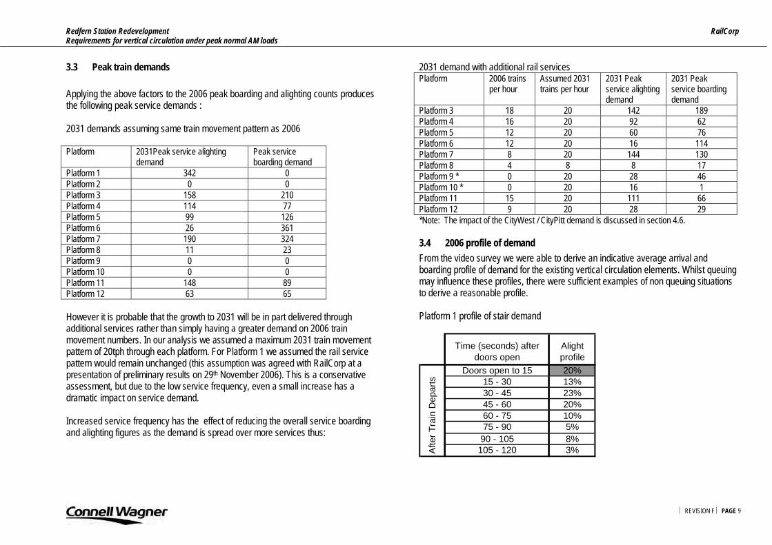
3.3 Peak train demands Applying the above factors to the 2006 peak boarding and alighting counts produces the following peak service demands : 2031 demands assuming same train movement pattern as 2006 Platform 2031Peak service alighting
demand Peak service boarding demand
Platform 1 342 0 Platform 2 0 0 Platform 3 158 210 Platform 4 114 77 Platform 5 99 126 Platform 6 26 361 Platform 7 190 324 Platform 8 11 23 Platform 9 0 0 Platform 10 0 0 Platform 11 148 89 Platform 12 63 65 However it is probable that the growth to 2031 will be in part delivered through additional services rather than simply having a greater demand on 2006 train movement numbers. In our analysis we assumed a maximum 2031 train movement pattern of 20tph through each platform. For Platform 1 we assumed the rail service pattern would remain unchanged (this assumption was agreed with RailCorp at a presentation of preliminary results on 29th November 2006). This is a conservative assessment, but due to the low service frequency, even a small increase has a dramatic impact on service demand. Increased service frequency has the effect of reducing the overall service boarding and alighting figures as the demand is spread over more services thus:
2031 demand with additional rail services Platform 2006 trains
per hour Assumed 2031 trains per hour
2031 Peak service alighting demand
2031 Peak service boarding demand
Platform 3 18 20 142 189 Platform 4 16 20 92 62 Platform 5 12 20 60 76 Platform 6 12 20 16 114 Platform 7 8 20 144 130 Platform 8 4 8 8 17 Platform 9 * 0 20 28 46 Platform 10 * 0 20 16 1 Platform 11 15 20 111 66 Platform 12 9 20 28 29 *Note: The impact of the CityWest / CityPitt demand is discussed in section 4.6. 3.4 2006 profile of demand From the video survey we were able to derive an indicative average arrival and boarding profile of demand for the existing vertical circulation elements. Whilst queuing may influence these profiles, there were sufficient examples of non queuing situations to derive a reasonable profile. Platform 1 profile of stair demand
Time (seconds) after doors open
Alight profile
Doors open to 15 20%15 - 30 13%30 - 45 23%45 - 60 20%60 - 75 10%75 - 90 5%90 - 105 8%105 - 120 3%A
fter T
rain
Dep
arts

Redfern Station Redevelopment RailCorp Requirements for vertical circulation under peak normal AM loads
⏐ REVISION F ⏐ PAGE 10
This profile is unique to platform 1 because there are no boarders for services arriving on platform 1. Observations suggest that the alighting load is relatively evenly distributed along its length, this results in a less peaked arrival profile at the stairs than that observed on other platforms. The duration of the profile is shorter than other profiles which may reflect the high percentage of passengers interchanging with other services (thereby walking with more urgency) and the occasional arrival of 6 car trains. For platforms 3 – 9 the following stair arrival and departure profile was derived from the count profile:
Time (seconds) before / after doors open/close
Alight profile
Board profile
-165 to -150 2%-150 to -135 1%-135 to -120 2%-120 to -105 2%-105 to -90 4%-90 to -75 4%-75 to -60 5%-60 to -45 7%-45 to -30 9%-30 to -15 11%
-15 to Doors open 14%Doors open to 15 21% 16%
15 - 30 28% 13%30 - 45 22% 7%
45 to Doors close 11% 4%Doors close to 15 7%
15 - 30 6%30 - 45 4%45 - 60 0%60 - 75 1%Af
ter T
rain
D
epar
ts
Befo
re T
rain
Arr
ives
This profile reflects the peak in demand for the stairs that occurs just before the train arrives and whilst the doors are open on the platform. The surveys revealed that a few passengers at the tail end of the profile are in no hurry to leave the platform and take over 2 minutes to clear the platform. For platform 11/ 12 a different profile was derived based on observations:
Time (seconds) before / after doors open/close
Alight profile
Board profile
-90 to -75 2%-75 to -60 4%-60 to -45 6%-45 to -30 15%-30 to -15 21%
-15 to Doors open 11%Doors open to 15 8% 15%
15 - 30 34% 13%30 - 45 24% 11%
45 to Doors close 18% 4%Doors close to 15 11%
15 - 30 2%30 - 45 2%45 - 60 1%60 - 75 0%
Befo
re T
rain
Ar
rives
Afte
r Tra
in
Dep
arts
This profile is different to Platforms 3 to 9 because the location of the vertical infrastructure is in a different location on the platform relative to the other platforms which are end loaded.

Redfern Station Redevelopment RailCorp Requirements for vertical circulation under peak normal AM loads
⏐ REVISION F ⏐ PAGE 11
3.5 2031 profiles The profile for 2031 of all platforms was modified to reflect the new location of the stairs & escalators on the alighting demand and the truncated profile associated with higher train frequencies. The profile utilised in the 2031 analysis is:
Time (seconds) before / after doors open/close
Alight profile
Board profile
-120 to -105 2%-105 to -90 4%-90 to -75 5%-75 to -60 6%-60 to -45 8%-45 to -30 10%-30 to -15 12%
-15 to Doors open 13%Doors open to 15 31% 18%
15 - 30 32% 14%45 to Doors close 25% 8%Doors close to 15 5%
15 - 30 4%30 - 45 3%Af
ter
Trai
n D
epar
ts
Befo
re T
rain
Arr
ives
For boarding passengers the profile is similar to the 2006 profile. The alighting profile is short and more peaked because the vertical circulation elements are located relatively evenly along the platform so there are more doors (and hence demand) within a short distance of each stair or escalator.
Redfern Station Redevelopment RailCorp Requirements for vertical circulation under peak normal AM loads
⏐ REVISION F ⏐ PAGE 12
4. Vertical circulation analysis
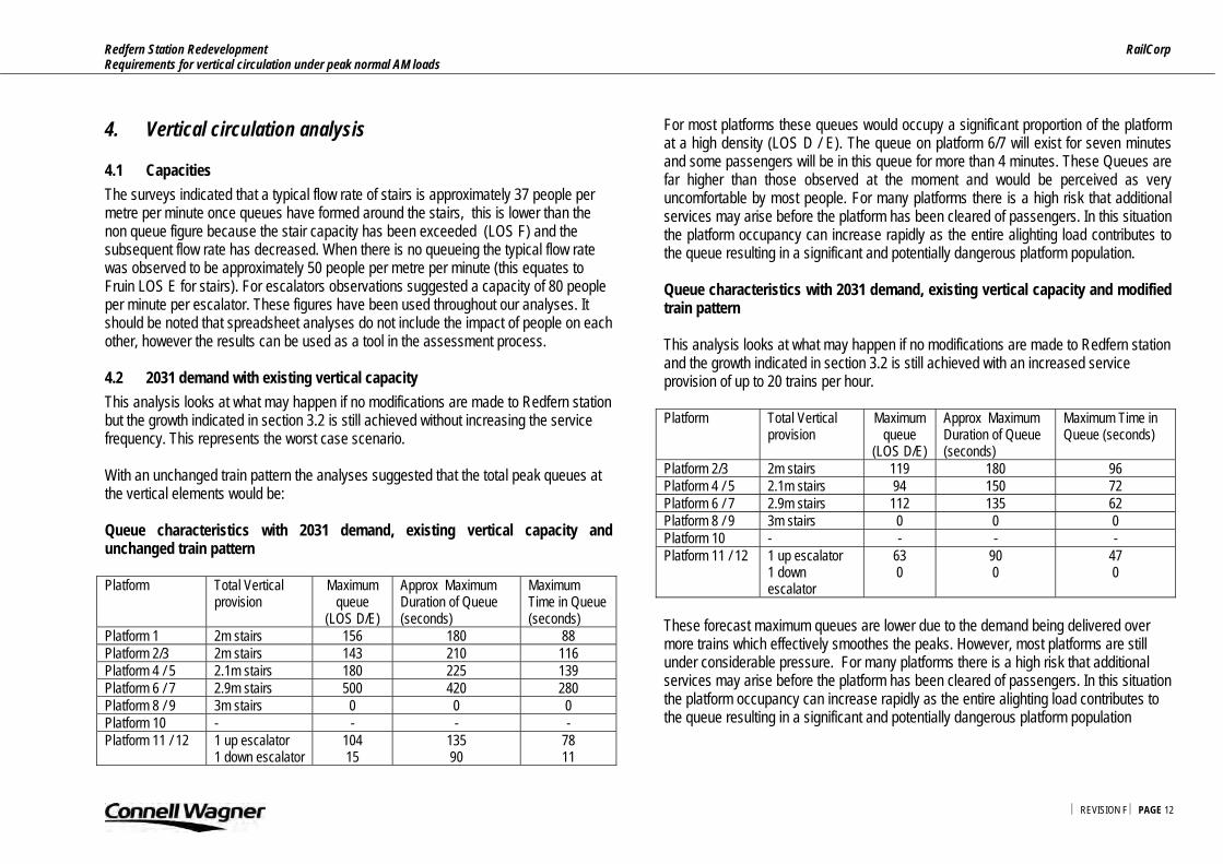
4.1 Capacities The surveys indicated that a typical flow rate of stairs is approximately 37 people per metre per minute once queues have formed around the stairs, this is lower than the non queue figure because the stair capacity has been exceeded (LOS F) and the subsequent flow rate has decreased. When there is no queueing the typical flow rate was observed to be approximately 50 people per metre per minute (this equates to Fruin LOS E for stairs). For escalators observations suggested a capacity of 80 people per minute per escalator. These figures have been used throughout our analyses. It should be noted that spreadsheet analyses do not include the impact of people on each other, however the results can be used as a tool in the assessment process. 4.2 2031 demand with existing vertical capacity This analysis looks at what may happen if no modifications are made to Redfern station but the growth indicated in section 3.2 is still achieved without increasing the service frequency. This represents the worst case scenario. With an unchanged train pattern the analyses suggested that the total peak queues at the vertical elements would be: Queue characteristics with 2031 demand, existing vertical capacity and unchanged train pattern Platform Total Vertical
provision Maximum
queue (LOS D/E)
Approx Maximum Duration of Queue (seconds)
Maximum Time in Queue (seconds)
Platform 1 2m stairs 156 180 88 Platform 2/3 2m stairs 143 210 116 Platform 4 / 5 2.1m stairs 180 225 139 Platform 6 / 7 2.9m stairs 500 420 280 Platform 8 / 9 3m stairs 0 0 0 Platform 10 - - - - Platform 11 / 12
1 up escalator 1 down escalator
104 15
135 90
78 11
For most platforms these queues would occupy a significant proportion of the platform at a high density (LOS D / E). The queue on platform 6/7 will exist for seven minutes and some passengers will be in this queue for more than 4 minutes. These Queues are far higher than those observed at the moment and would be perceived as very uncomfortable by most people. For many platforms there is a high risk that additional services may arise before the platform has been cleared of passengers. In this situation the platform occupancy can increase rapidly as the entire alighting load contributes to the queue resulting in a significant and potentially dangerous platform population. Queue characteristics with 2031 demand, existing vertical capacity and modified train pattern This analysis looks at what may happen if no modifications are made to Redfern station and the growth indicated in section 3.2 is still achieved with an increased service provision of up to 20 trains per hour. Platform Total Vertical
provision Maximum
queue (LOS D/E)
Approx Maximum Duration of Queue (seconds)
Maximum Time in Queue (seconds)
Platform 2/3 2m stairs 119 180 96 Platform 4 / 5 2.1m stairs 94 150 72 Platform 6 / 7 2.9m stairs 112 135 62 Platform 8 / 9 3m stairs 0 0 0 Platform 10 - - - - Platform 11 / 12
1 up escalator 1 down escalator
63 0
90 0
47 0
These forecast maximum queues are lower due to the demand being delivered over more trains which effectively smoothes the peaks. However, most platforms are still under considerable pressure. For many platforms there is a high risk that additional services may arise before the platform has been cleared of passengers. In this situation the platform occupancy can increase rapidly as the entire alighting load contributes to the queue resulting in a significant and potentially dangerous platform population
Redfern Station Redevelopment RailCorp Requirements for vertical circulation under peak normal AM loads
⏐ REVISION F ⏐ PAGE 13
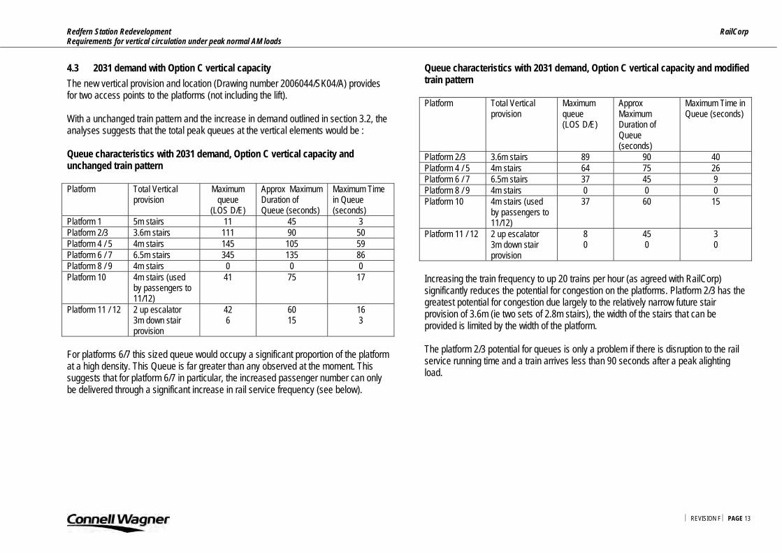
4.3 2031 demand with Option C vertical capacity The new vertical provision and location (Drawing number 2006044/SK04/A) provides for two access points to the platforms (not including the lift). With a unchanged train pattern and the increase in demand outlined in section 3.2, the analyses suggests that the total peak queues at the vertical elements would be : Queue characteristics with 2031 demand, Option C vertical capacity and unchanged train pattern Platform Total Vertical
provision Maximum
queue (LOS D/E)
Approx Maximum Duration of Queue (seconds)
Maximum Time in Queue (seconds)
Platform 1 5m stairs 11 45 3 Platform 2/3 3.6m stairs 111 90 50 Platform 4 / 5 4m stairs 145 105 59 Platform 6 / 7 6.5m stairs 345 135 86 Platform 8 / 9 4m stairs 0 0 0 Platform 10
4m stairs (used by passengers to 11/12)
41 75 17
Platform 11 / 12
2 up escalator 3m down stair provision
42 6
60 15
16 3
For platforms 6/7 this sized queue would occupy a significant proportion of the platform at a high density. This Queue is far greater than any observed at the moment. This suggests that for platform 6/7 in particular, the increased passenger number can only be delivered through a significant increase in rail service frequency (see below).
Queue characteristics with 2031 demand, Option C vertical capacity and modified train pattern Platform Total Vertical
provision Maximum queue (LOS D/E)
Approx Maximum Duration of Queue (seconds)
Maximum Time in Queue (seconds)
Platform 2/3 3.6m stairs 89 90 40 Platform 4 / 5 4m stairs 64 75 26 Platform 6 / 7 6.5m stairs 37 45 9 Platform 8 / 9 4m stairs 0 0 0 Platform 10
4m stairs (used by passengers to 11/12)
37 60 15
Platform 11 / 12
2 up escalator 3m down stair provision
8 0
45 0
3 0
Increasing the train frequency to up 20 trains per hour (as agreed with RailCorp) significantly reduces the potential for congestion on the platforms. Platform 2/3 has the greatest potential for congestion due largely to the relatively narrow future stair provision of 3.6m (ie two sets of 2.8m stairs), the width of the stairs that can be provided is limited by the width of the platform. The platform 2/3 potential for queues is only a problem if there is disruption to the rail service running time and a train arrives less than 90 seconds after a peak alighting load.
Redfern Station Redevelopment RailCorp Requirements for vertical circulation under peak normal AM loads
⏐ REVISION F ⏐ PAGE 14
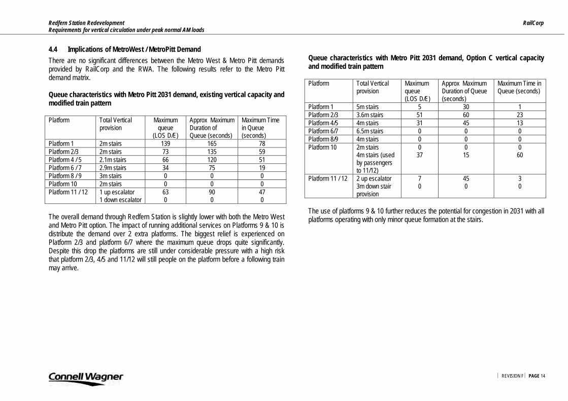
4.4 Implications of MetroWest / MetroPitt Demand There are no significant differences between the Metro West & Metro Pitt demands provided by RailCorp and the RWA. The following results refer to the Metro Pitt demand matrix. Queue characteristics with Metro Pitt 2031 demand, existing vertical capacity and modified train pattern Platform Total Vertical
provision Maximum
queue (LOS D/E)
Approx Maximum Duration of Queue (seconds)
Maximum Time in Queue (seconds)
Platform 1 2m stairs 139 165 78 Platform 2/3 2m stairs 73 135 59 Platform 4 / 5 2.1m stairs 66 120 51 Platform 6 / 7 2.9m stairs 34 75 19 Platform 8 / 9 3m stairs 0 0 0 Platform 10 2m stairs 0 0 0 Platform 11 / 12
1 up escalator 1 down escalator
63 0
90 0
47 0
The overall demand through Redfern Station is slightly lower with both the Metro West and Metro Pitt option. The impact of running additional services on Platforms 9 & 10 is distribute the demand over 2 extra platforms. The biggest relief is experienced on Platform 2/3 and platform 6/7 where the maximum queue drops quite significantly. Despite this drop the platforms are still under considerable pressure with a high risk that platform 2/3, 4/5 and 11/12 will still people on the platform before a following train may arrive.
Queue characteristics with Metro Pitt 2031 demand, Option C vertical capacity and modified train pattern Platform Total Vertical
provision Maximum queue (LOS D/E)
Approx Maximum Duration of Queue (seconds)
Maximum Time in Queue (seconds)
Platform 1 5m stairs 5 30 1 Platform 2/3 3.6m stairs 51 60 23 Platform 4/5 4m stairs 31 45 13 Platform 6/7 6.5m stairs 0 0 0 Platform 8/9 4m stairs 0 0 0 Platform 10
2m stairs 4m stairs (used by passengers to 11/12)
0 37
0 15
0 60
Platform 11 / 12
2 up escalator 3m down stair provision
7 0
45 0
3 0
The use of platforms 9 & 10 further reduces the potential for congestion in 2031 with all platforms operating with only minor queue formation at the stairs.

Redfern Station Redevelopment RailCorp Requirements for vertical circulation under peak normal AM loads
⏐ REVISION F ⏐ PAGE 15
5. 2031 Option C concourse and gate capacity
5.1 Concourse capacity – existing train pattern Using the spreadsheet model we have examined the ability of the paid concourse structure over surface tracks to cater for a worst case demand. In this case, even if every passenger associated with the peak hour boarding and alighting demand for every platform service (current provision)was present on the bridge at the same time, the total occupancy would be 2,150 and the average area per person is approximately 0.68m2 per person (discounting 15% for lifts etc) which represents a Fruin Level of Service D for queues or LOS E for walking passengers. Whilst the STEPS modeling will confirm the dynamic Level of Service, it is reasonable to assume that the peak occupancy of the concourse would not approach these levels as it is difficult to imaging a scenario where every boarder and alighter for every service would be present on the concourse. 5.2 Concourse capacity – additional 2031 service pattern If all the passengers associated with the 2031 peak hour service (boarders and alighters) occupied the paid concourse structure over surface tracks at the same time there would be 1446 people on the concourse and the average area per person is approximately 1m2 per person (discounting 15% for lifts etc) which represents a Fruin Level of Service B for queues or LOS D for walking passengers. It is considered very unlikely that the concourse would ever be subjected to this demand. The Option C design therefore has some flexibility to cater for unexpected peak demands and should in general provide a very good level of service for RailCorp customers. Based on the preliminary spreadsheet modelling we conclude that the concourse has adequate dimensions to cater for the 2031 demand. The dynamic LOS will be forecast using the STEPS simulation model.
5.3 2031 provision of ticket gate capacity The elements to consider when analyzing gate activity is the directional split of the demand, the profile and magnitude of the demand and the number and capacity of the gates. The demand matrix was provided by RailCorp and the RWA and includes the impact of RWA landuse estimates. The exit demand directional split is that given in the Redfern Station Redevelopment – Transport and Movement, July 2002 report by PPK consultants. This reflects the assumptions that the majority of the alighting demand will be heading for the University. The entry demand is an assumption which reflects the location of the majority of the residential areas. These assumption weres agreed with RailCorp at a presentation of preliminary results on 29th November 2006. Exit demand split
To West 60%
To East 40%
Entry demand split
From West 20%
From East 80%Provision
Entry Exit gates West 2 5gates East 4 4
rate 20 per minute The provision of entry & exit gates has been matched to the magnitude of the entry and exit demands in the AM peak.

Redfern Station Redevelopment RailCorp Requirements for vertical circulation under peak normal AM loads
⏐ REVISION F ⏐ PAGE 16
The worst case demand was assumed to be the entry and exit for the peak service on each platform within a 3 minute period, which reflects the shorter profiles associated with higher train frequencies. So the demand per service is reduced but the profile is shorter. The results of the spreadsheet are presented in the following table:
ENTRY EXITCapacity per 3 minutesWest Gate Capacity 120 300East entry Capacity 240 240
Total demand 255 546
West demand 51 327
East demand 204 218
West Spare Gate Cap 69 -27
East Spare entry Cap 36 22 Based on the assumptions it can be concluded that there is sufficient gate capacity to cater for the peak service demands in 2031 based on the assumptions summarized previously. Should a different split be observed in practice, then the direction of the gates’ operation can be modified and it is recommended that provision is made for additional gates should they be required.

Redfern Station Redevelopment RailCorp Requirements for vertical circulation under peak normal AM loads
⏐ REVISION F ⏐ PAGE 17
6. Summary
6.1 Summary The analyses to date suggests that the current Jackson Teece design known as Option C (Drawing number 2006044/SK04/A) will operate reasonably well in 2031 with the proposed increase in vertical transport provision. The Option C concourse appears to have sufficient capacity to cater for the peak demands, platform 2/3 is forecast to have some queuing at platform level mainly because this platform has a high demand but the width of the stairs is constrained by the relatively narrow platform width. However the typical peak queue will exist for less than 90 seconds and the maximum time for a person in this queue will be less than 40 seconds. The spare capacity on the other platforms provides some capability to cater for variations in demand, so whilst platform 2/3 should be able to cater for ‘normal’ operations, there is a greater potential for congestion should there be service disruptions leading to greater than expected train boarding or alighting demands, or a very short headway. Based on the assumed directional split it appears that the provision of 7 gates to the west and 8 gates at the eastern entrance is adequate for the forecast peak station entry and exit demands. However it is recommended that provision is made for additional gates if required. The use of the STEPS pedestrian simulation modeling package will provide a more robust assessment of the design’s operational capability.

Redfern Station Redevelopment RailCorp Requirements for vertical circulation under peak normal AM loads
⏐ REVISION F ⏐ PAGE 18
Appendix A: Redfern Station Upgrade Concept Design – Option C

Redfern Station Redevelopment RailCorp Requirements for vertical circulation under peak normal AM loads
⏐ REVISION F ⏐ PAGE 19

Redfern Station – Pedestrian Evacuation Fire Engineering Report Jackson Teece 28 March 2007 Reference 23443/FER Revision 02
Connell Wagner Pty Ltd ABN 54 005 139 873 116 Military Road Neutral Bay New South Wales 2089 Australia Telephone: +61 2 9465 5599 Facsimile: +61 2 9465 5598 Email: [email protected] www.conwag.com

Document Control
Document ID: I:\23443\ENG\FSE\EGRESS\REDFERN STATION - PEDESTRIAN EVACUATION 280307.DOC
Rev No Date Revision Details Typist Author Verifier Approver
00 21 November 2006 Draft RA PAB LRC
01 11 December 2006 New Effective Widths PAB PAB LRC
02 28 March 2007 Options C, D and E Analysis - Final PAB PAB LRC
A person using Connell Wagner documents or data accepts the risk of: a) Using the documents or data in electronic form without requesting and checking them for accuracy against the original hard copy version. b) Using the documents or data for any purpose not agreed to in writing by Connell Wagner.

Fire Engineering Report Jackson Teece Redfern Station – Pedestrian Evacuation
⏐ 28 MARCH 2007 ⏐ REVISION 02 ⏐ PAGE I
Contents
1. Scope 1 1.1 General 1 1.2 Regulatory Framework 1 1.3 The Fire Safety Engineering Process 2 1.4 Stakeholders 2
2. Codes and Standards 3 2.1 NFPA 130 3
3. Station Characteristics 4 3.1 Occupancy 4 3.2 Location 4 3.3 Size and Shape 4 3.4 Platform Options 4 3.5 Evacuation Procedures 5 3.6 Maintenance 5
4. Station Occupants 6 4.1 General 6 4.2 Occupant groups 6 4.3 Design group 1 – Staff Members 6 4.4 Design group 2 7
5. Objectives & Methodology 8 5.1 Determine Pedestrian Flow Parameters 8 5.2 Methodology 8
6. Occupant Load Exit Capacity – Worst Case 9 6.1 Calculating Occupant Load Exit Capacity – Worst Case Scenario 9 6.2 Acceptance Criteria 10 6.3 Worst Case Evacuation Times 11
7. Summary of Results 7.1 Summary of Results – Worst Cases
8. Conclusions
9. References Appendix A: Definitions

Fire Engineering Report Jackson Teece Redfern Station – Pedestrian Evacuation
⏐ 28 MARCH 2007 ⏐ REVISION 02 ⏐ PAGE 1
1. Scope 1.1 General Connell Wagner have been engaged by Jackson Teece to provide a review of pedestrian egress at Redfern Rail Station. The intent of this Fire Safety Engineering Report is to assess the pedestrian performance capacity of the most onerous platforms (Dual centre platforms 2/3 and 11/12). This assessment will review current worst case populations for the current layout of the platforms. The report will also assess the pedestrian performance capacity of the same platforms based on a proposed future layouts as preferred by Railcorp and Redfern-Waterloo Authority and incorporating feed back from other local government services. The pedestrian performance is to the requirements of NFPA130 - Standard for Fixed Guideway Transit and Passenger Rail Systems (2007 Edition)[1]. 1.2 Regulatory Framework The proposed upgrade of Redfern Station is in accordance with progressing the strategies and objectives of the Redfern-Waterloo Built Environment Plan and State Environmental Planning Policy (Major Projects) 2005. Railcorp and Australian standards play a large role in determining the current and future pedestrian capacity of Redfern station. This document identifies that a performance based approach is likely to be required to satisfy RailCorp standards and guidelines, NFPA 130 and the Building Code of Australia, based on current and (most) future designs. 1.2.1 RailCorp Standards and Guidelines The relevant code is Railcorp Station Design Guide – July 2006 [2]. The State Rail Authority of NSW’s “Guidelines for Fire and Life Safety in the Construction of Railway Facilities – Volume 2” has been used for guidance only.
1.2.2 NFPA 130 NFPA Standard for Fixed Guideway Transit and Passenger Rail Systems (2007 Edition) is an American code governing fire and life safety. 1.2.3 The Building Code of Australia Compliance with the Building Code of Australia [3] may be achieved by meeting the ‘deemed to satisfy’ or prescriptive provisions of the Building Code of Australia. Alternatively, compliance may be achieved by meeting the intent of the performance requirements of the Building Code of Australia. 1.2.4 Population Assumptions NFPA130 makes recommendations as to how the platform occupant load may be calculated. For entraining and train loads, the sum of the loads for each track serving a platform shall be determined. Statistical data from State Rail has been provided for the current population and the projected 2031 population. These projected populations include anticipated growth for the rail corridor generally and the Redfern-Waterloo Authority redevelopment in particular. This analysis examines a maximum population arriving and entraining on platform 2/3 or 11/12 ESR and is in excess of the projected 2031 figures. Therefore, the analysis is conservative. The selection of Platform 2/3 and Platform 11/12 is considered appropriate as: • The greatest entraining and detraining populations occur on platforms 3 and 11
respectively during the a.m. peak; • No outbound trains stop on platform 2 during the a.m. peak; • The outbound population entraining and detraining on platform 12 in the a.m. peak
is negligible; • The populations used in this report are more onerous when compared to the data
provided by Railcorp as a maximum alighting population is used. These assumptions should be reviewed by the relevant stakeholders.

Fire Engineering Report Jackson Teece Redfern Station – Pedestrian Evacuation
⏐ 28 MARCH 2007 ⏐ REVISION 02 ⏐ PAGE 2
1.3 The Fire Safety Engineering Process Fire Safety Engineering generally follows the International Fire Engineering Guidelines (IFEG) [4] produced by the Australian Building Code Board in 2005.
The fire safety engineering process in brief is as follows: • Conduct meetings with stakeholders to discuss issues, assessment
methodologies and acceptance criteria. • Carry out an analysis of the issues using an agreed methodology. • Draw conclusions and recommendations. • Prepare Fire Engineering Report for submission to the certifying authority. The Fire Safety Engineering process is concerned with compliance with the Building Code of Australia and is concentrated primarily on life safety. 1.4 Stakeholders The following organisations have been identified as being directly involved in the fire safety engineering process and consequently will be participants in the production of the Fire Engineering Report. Organisation Role Contact Jackson Teece Client Carlos Frios Jackson Teece Client Munir Vahanvati Connell Wagner Civil Engineer Phil Robinson Connell Wagner Senior Fire Engineer Lee Clark Connell Wagner Fire Engineer Peter Blundell

Fire Engineering Report Jackson Teece Redfern Station – Pedestrian Evacuation
⏐ 28 MARCH 2007 ⏐ REVISION 02 ⏐ PAGE 3
2. Codes and Standards 2.1 NFPA 130 Applicability – NFPA130 is a referenced document in the Jackson Teece (and Railcorp) brief. The scope of NFPA includes the: “fire protection requirements for underground, surface, and elevated fixed guideway transit and passenger rail systems including trainways, vehicles, and outdoor vehicle maintenance and storage areas, and for life safety from fire in fixed guideway transit and passenger rail system stations, trainways, vehicles, , and outdoor vehicle maintenance and storage areas.” Redfern Station falls within this scope. In brief, the sections of NFPA 130 that are applicable to the fire safety assessment for this project are summarised below: Chapter 5 Means of Egress – This chapter is applicable to all rail stations whether above or below ground. The following sections of Chapter 5 were considered when determining the pedestrian capacities: 5.5.1 – General. Provisions for egress including alternate egress and common paths of travel; 5.5.2 – Escalators. Acceptance as a form of egress, stopped or otherwise; 5.5.5 – Occupant Load. Lists the criteria for determining platform and train occupant loads, platform and station evacuation times. Appendix C Emergency Egress Appendix C gives advice and information on egress from stations. The following items are noted:
That the spreadsheet calculations that form part of this report are based around Centre-Platform Station Sample calculations; • The maximum allowable travel distance is 100m; • The maximum platform evacuation time is 4 minutes; • The maximum evacuation time to a place of safety is 6 minutes; • The worst case scenario assumes a 100% population of an 8 car, 200 person per
car, detraining train plus a 15% entraining population waiting on the platform;

Fire Engineering Report Jackson Teece Redfern Station – Pedestrian Evacuation
⏐ 28 MARCH 2007 ⏐ REVISION 02 ⏐ PAGE 4
3. Station Characteristics 3.1 Occupancy 3.1.1 Station classification and Usage The station is classified as a Category A building Under the Railcorp Station Design Guide. This category of station is due to the fact is has an underground component. A category A station is categorised by very high patronage (> 20,000 per day), 24 hour staff presence, exceptional operational and commercial importance and an exceptional level of maintenance. 3.1.2 Function Redfern Station accommodates a mixture of suburban, interurban and intercity trains. Redfern is one of Sydney’s major rail stations. Many thousands of people use Redfern daily and represents a (the first) major conjunction of southern, south west, western, north west and intercity rail lines. Due to its topography, Redfern is used as a major interchange point for many commuters. It is also a major destination for students of Sydney University while also providing services to the eastern suburbs. It is also a popular point of entrainment when special events are being run at Homebush (Olympic site) eg concerts, sporting events and The Royal Easter Show. 3.2 Location 3.2.1 Proximity to other buildings and boundaries Redfern station is located at the intersection of Lawson and Gibbons Streets, Redfern, just a few kilometres south of Sydney CBD. There are many well known Sydney buildings/landmarks in proximity to the station, therefore space separation will be a necessary consideration with regard future development. 3.2.2 Proximity to fire stations State Rail have their own fire emergency service located at Wilson Street, Redfern. The Local Fire Brigade Station is located at 111 George Street, Redfern. Both services are less than 5 minutes from the station. The State Rail station will be moved to Pitt Street, Central Station, in the years to come. At this time, potential issues relating to the
relocation of the fire service is not part of this fire and life safety assessment. It is envisaged that it will be part of considerations during the design development stage.
3.3 Size and Shape The railway station consists of twelve platforms running approximately in a north east to south west direction. Platforms 1 through 10 are above ground while platform 11/12 is underground and forms part of the Illawarra line from Bondi Junction to Sutherland (and beyond). With the exception of platform 2/3, a single storey brick building resides on each platform. These are used as communication and control rooms and previously as waiting and storage rooms. Platform areas range from approximately 500m2 on platform 1 and 10 up 1500m2 on platform 11/12. A concourse level to the north of the station serves all platforms. It provides pedestrian interchange to all platforms, access and egress to Lawson and Gibbons Streets. Ticketing offices and Railcorp offices are located on the concourse level. All current egress from the platform levels is via this concourse. Currently, there is no disabled lift access from any platforms. The most easterly above ground platform, Platform 10, is rarely used as a train destination but more as a path of travel for commuters wishing to access the Australian Technology Park to the south of the station. 3.4 Platform Options This report reviews the evacuation timings with respect to Platforms 2/3 and 11/12 ESR for the current station and compares this to the proposed design options. The options have been identified as Option D, Option E and Option C. Option D embraces the following changes for the respective platforms. Platform 2/3 will have an intermediate concourse built above the existing platform. This concourse begins below and to the south of the existing concourse and covers almost 50% of the platform. Egress from the platform to the intermediate concourse is via one set of stairs (at the southern end) and an “up only” escalator located in the centre of the concourse. Egress from the intermediate concourse to the existing concourse is via stairs at the northern end. Platform 11/12 ESR remains the same but includes an emergency stair located at the southern end of the platform.

Fire Engineering Report Jackson Teece Redfern Station – Pedestrian Evacuation
⏐ 28 MARCH 2007 ⏐ REVISION 02 ⏐ PAGE 5
Egress for Platform 11/12 remains the same for Option E. Platform 2/3 however, now includes a stair located at the southern end of the platform. Option E includes greater northern concourse area for all platform and increased travel distance to the new exit to Gibbons Street. Exit numbers to Gibbons Street have been increased from 3 to 11 speed gates. Option C reviews the proposed concourse level to be located approximately midway along the above ground platforms in an east west direction. A public concourse/footbridge will run parallel to the concourse opening up access between Gibbons/Marion Street and Ivy/Wilson Street. All above ground platforms will have access/egress via two stairs. Each stair will be from platform to concourse, one to the south and one to the north. The existing northern concourse is to be retained but open to public access. There is potential to retain the existing platform stairs at the northern end of the platforms as emergency egress only. Access egress to the ESR platform 11/12 is yet to be determined. There is potential to add additional emergency egress from the southern and northern ends of the platform. 3.5 Evacuation Procedures 3.5.1 Emergency Management Operational procedures for the management of emergency situations shall be predefined and recorded and readily accessible for inspection by staff members. Staff shall be trained in the emergency procedures, staff will be assigned to emergency roles and emergency procedures shall be included in all staff duties. Patrons of the station will be advised and informed appropriately to discourage panic or stress during an emergency situation. All station officers/masters shall be trained for emergency response and their training will be kept current through periodic drills and review courses.
3.5.2 Evacuation plans Evacuation plans shall be located in prominent locations on all platforms, which show occupants possible egress routes. An emergency procedure shall be developed to address specifically the various types of emergencies that might be experienced whether the fire was to occur on a platform or on a train that has stopped at the station. 3.5.3 Emergency Procedures Fire and smoke emergencies shall include information and procedures defining the following for different emergency scenarios: • location of the fire in the train, station or ancillary accommodation; • fire detection systems; • fire protection systems and devices and their location/point of initiating
operation; • exit/entrance locations to the station, including vehicular routes; • agencies to be notified and their telephone number (ie. local fire brigade station,
police, ambulance services). 3.6 Maintenance 3.6.1 Frequency and adequacy of maintenance regimes All essential fire safety systems shall be the subject of regular periodic inspection and maintenance by reputable contractors. The maintenance shall follow the Australian Standard AS1851 for those systems, including scheduled works as described within these standards.

Fire Engineering Report Jackson Teece Redfern Station – Pedestrian Evacuation
⏐ 28 MARCH 2007 ⏐ REVISION 02 ⏐ PAGE 6
4. Station Occupants 4.1 General Future disabled access will be in accordance with the CityRail Design Guide 2006 and AS1428.2. 4.2 Occupant groups There are basically two occupant groups. These are as follows: • Station Staff and Contractors • Passengers (able/disabled) 4.3 Design group 1 – Staff Members The first design group is that of staff/contracting staff. Due to the size of this station it is expected that on a day to day basis there will be a significant number of regular staff will be present. Contract staff that maybe working on the lines within the station and transit police may also be present. Other contract staff may include maintenance staff, cleaning staff etc. 4.3.1 Distribution Staff are categorised as follows: • Train Crewing (Train Drivers and Guards) • Operations (off site) • Station Operations (Staff operating the station) • Presentation Services (Cleaners) • Passenger Fleet Maintenance • Metro-City (Rail infrastructure maintenance) • Transit Police The staff will concentrate mainly around the office areas on the concourse and each platform.

Fire Engineering Report Jackson Teece Redfern Station – Pedestrian Evacuation
⏐ 28 MARCH 2007 ⏐ REVISION 02 ⏐ PAGE 7
4.3.2 Number Station staff numbers are as follows: • Monday to Friday (am) – 23 Staff and 4 Transit Officers • Monday to Friday (pm) – 17 Staff and 4 Transit Officers • Saturday and Sunday (am) – 15 Staff and 4 Transit Officers • Saturday and Sunday (pm) – 13 Staff and 4 Transit Officers 4.3.3 Age The staff are all in the working age group (18 to 65).
4.3.4 Mobility The staff are mobile, are expected to move at an average speed of travel. The hearing and visual ability is in the normal range for the population. Patrons with more severe mobility issues will use the lifts and are not considered in the general egress assessment.
4.3.5 State of Awareness All staff members will be conscious and alert. They will not be under the influence of alcohol or narcotics. 4.3.6 Familiarity with Exit Routes The staff are trained in emergency evacuation and are likely to respond with little panic in an emergency. The staff will not require additional assistance in an emergency and will be familiar with escape routes and exits. Occupants will be alert and awake. 4.4 Design group 2 4.4.1 Distribution The patrons will be distributed about the platforms and concourse. Most occupants will be found on the busier platforms (2/3 and 11/12) and the concourse area.
4.4.2 Age The age of the patrons is expected to be in the normal range for the population including accompanied children. 4.4.3 Mobility The patrons will be mobile, although some customers will have mobility issues and may move at the lower range of the expected speed of travel. The hearing and visual ability is in the normal range for the population.
4.4.4 Familiarity with exits The customers are likely to be reasonably familiar with the platform layout and egress routes.

Fire Engineering Report Jackson Teece Redfern Station – Pedestrian Evacuation
⏐ 28 MARCH 2007 ⏐ REVISION 02 ⏐ PAGE 8
5. Objectives & Methodology 5.1 Determine Pedestrian Flow Parameters Redfern station is to be upgraded and is central to the revitalisation of Redfern-Waterloo. Architects Jackson Teece were employed to provide a series of station options in keeping with the Redfern Waterloo urban vision. Connell Wagner (Fire Safety Engineers) were employed because of their expertise in the area of pedestrian egress to help determine, at a high level, which of the proposed Jackson Teece options was desirable from a pedestrian flow perspective. The Option D, Option E and Option C station options were assessed against a maximum population. 5.2 Methodology Station Capacity and evacuation times of the platforms are very much dependent on hard data with reference to passenger movements. That is, station entries, exits and interchanges. Data provided to Connell Wagner at the outset from a 2001 transport and movement report was recognised as being potentially obsolete. Additional, future populations were only projected to 2016. Railcorp were able to provide more accurate current and future data including Redfern-Waterloo Authority landuse estimates. Fifteen minute a.m. and p.m. peaks were identified and compared. The a.m. peak was identified as the more onerous of the two peaks. The station movement data provided was then interpolated to determine population numbers for the 5 minute “peak within the peak”. To collaborate the accuracy of this data, video footage was taken for on each platform. This was conducted 15 minutes either side of the a.m. peak during days in September, October and November, 2006.
Platform useable areas were determined from plans and Railcorp’s “A guide to Platform Widths”. Using pedestrian numbers and John J Fruin’s “Pedestrian Planning and Design”, Levels of Service for the station were determined. This data will be utilised later as part of the detailed pedestrian modelling for the station. NFPA 130 was utilised to determine the evacuation timings, for the most onerous platforms. This examined platforms 2/3 and ESR platforms 11/12 with worse populations. Option D, Option E and Option C evacuation timings for platform and station were compared to NFPA130 recommendations. The evacuation timings for the current station layout were included for perspective.

Fire Engineering Report Jackson Teece Redfern Station – Pedestrian Evacuation
⏐ 28 MARCH 2007 ⏐ REVISION 02 ⏐ PAGE 9
6. Occupant Load Exit Capacity – Worst Case 6.1 Calculating Occupant Load Exit Capacity – Worst Case Scenario The occupant load at Redfern Railway Station shall be based on the calculated trainload entering the station in normal traffic direction during the peak 15-minute period plus the simultaneous entraining load awaiting a train. As a basis for computing the detraining load during an emergency, not more than one train will unload at each platform analysed. The intent is to analyse platform 2/3 and Eastern Suburbs Rail (ESR) platform 11/12. Platform 2/3 represents the busiest of the above ground platforms. ESR Platform 11/12 is unique in that it is the only underground platform. The occupant load exit capacity of Redfern Railway Station for platforms 2/3 and ESR 11/12 shall be based upon the maximum load capacity at each of the platforms. The maximum sized train that would ever be expected to stop at platforms 2/3 and ESR 11/12 is an eight-carriage train. This size of train has a maximum carrying capacity of 1600 occupants. That is, 200 persons per carriage. As it is not possible to increase the length of the platforms and hence increase the number of carriages to detrain, the maximum occupant load will be limited to 8 carriages. The entraining loads for each platform has been taken as 15% of the detraining population based as a 15% surge population. This population is in excess of the projected 2031 data for these platforms. The worst case scenario for calculation of the adequacy of the exits has therefore been assumed on the basis one full train has stopped (assuming its on fire) within the station and that 240 occupants (1600 x 1.15) are waiting on the platforms. The total number of occupants on Platform 2/3 or ESR 11/12 is therefore 1600 (fully loaded train) and 240 entraining patrons. The maximum number is therefore 1,840 occupants.
For the Option D and Option E options, variation of and additional egress has been considered for platform evacuation. The concourse level egress at the northern end of the station has been expanded for the Option E option. For platform 2/3 Option D, one escape route is available. The route rises from the north end of the platform to an intermediate concourse level. Travel along this concourse to the existing concourse, to a point of safety outside the turnstile area in Lawson Street has been analysed.. For platform 2/3 Option E, two escape routes are available. The routes rise from the north and south ends of the platform. As mentioned above, travel to the north is via an intermediate concourse level. The route to the south is via an emergency stair to a concourse/bridge level. The station evacuation will analyse the travel along the intermediate concourse to the north to the existing concourse to a point of safety outside the turnstile in Lawson Street. This is considered the more onerous route. For Platform 2/3,Option C, the two stairs that rise north and south from the platform to the concourse are analysed. For station evacuation time, the additional travel distance along the concourse and through the south west exit turnstiles to the public concourse is considered. For Platform 11/12 Option D and Option E, three escape routes are available. These are via the emergency stairs to the south of the platform, the stairs in the centre of the platform and the escalator(s) to the north of the platform. The station evacuation will analyse travel along the stairs to the existing concourse to a point of safety outside the turnstile in Gibbons Street. This is considered the more onerous route. The Base Plus Case will consider the additional travel distance and turnstiles proposed. For Option D and Option E, the width of all stairs is 1.7m wide. The escalator on Platform 2/3 is 1.0m wide and the escalator(s) on Platform 11/12 is 1.2m wide. The second escalator on Platform 11/12 has not been considered (as it may be potentially operating in a downward direction). In Option C, Platform 2/3, the width of the stairs to the paid concourse are 2m each. On platform 11/12, there are two up escalators 1m wide each and a stair 1.3m wide up to the pedestrian link. There are two emergency stairs located at each end of the platform. The northern stair is 3.2m wide and the southern stair is 2.9m wide.

Fire Engineering Report Jackson Teece Redfern Station – Pedestrian Evacuation
⏐ 28 MARCH 2007 ⏐ REVISION 02 ⏐ PAGE 10
Occupants when walking up stairs or along corridors do not usually walk directly against a wall. A boundary layer of 150mm is normally adopted. However, the video footage taken at Redfern station when pedestrian conditions are equivalent to Fruin’s Level of Service “F”, contradict the need for a boundary layer to be considered. It is assumed that for the analysis of the current station layout, that platform 2/3 population evacuates via Lawson Street while the platform 11/12 population evacuates via Gibbons Street. In Option C, the additional emergency stairs considered in the ESR platform 11/12 analysis, are located toward the southern and northern end respectively. As the exact location of these emergency stairs is unknown, it is assumed the maximum travel distance to a point of safety is via the existing stairs to the pedestrian link, along platform 10 to the stairs, then up the stairs to the paid concourse and out the turnstiles to the east (of the paid concourse). 6.2 Acceptance Criteria In accordance with the recommendations of section 5.5.6.1 of the NFPA 130, there shall be sufficient exit lanes to evacuate the platform occupant load from the station platform in 4 minutes. This figure may however be modified as it is based upon an enclosed station whereby ventilation conditions are restricted. Platforms at Redfern are external and open to atmosphere with the exception of ESR platform 11/12. Smoke and heat generated by the combustible items (station office, train etc.) will be dissipated to atmosphere and therefore will not impede an occupants escape. It is predominantly the radiant heat of a burning train/building on a platform that needs to be considered. If a burning train pulls into the station the fleeing occupants may have difficulty evacuating due to the limited number of escape routes away from the fire. The report seeks to analyse the evacuation times of the options, some with additional escape routes. The NFPA guidance suggests that the maximum travel distance to an exit from any point on the platform should not exceed 100m (See NFPA130 5.5.6.1.1).For the Base and Base Plus options, the total distance to the platform stairs will be 65m for platform 2/3 and 28m for ESR platform 11/12 (this is approximately the midpoint between the south central stair and the south emergency stair).
For Option C, platform 2/3, the distance will be 58m from the southernmost carriage door to the southern stair. For ESR platform 11/12, this will also be 28m. In accordance with the recommendations of section 5.5.6.2 of the NFPA 130, there shall be sufficient exit lanes to evacuate the station from the most remote point on the station platform to a place of safety in 6 minutes. For Option D and Option E, platform 2/3, there is approximately 5.5m of total vertical travel distance where a patron has to travel up both sets of stairs. The walking speed of patrons will be slower over this portion of egress path and will be accounted for when calculating occupant movement times. There is approximately 46m of travel along the intermediate concourse in Option E to consider, and 17m over the existing concourse, through the turnstiles and out onto Lawson Street that form part of the timing. For ESR platform 11/12, there is approximately 12.23m of the vertical travel distance where a patron has to travel up stairs as well as 17m across the intermediate concourse. The walking speed of patrons will be slower over the vertical portion of the egress path and will be accounted for when calculating occupant movement times. Additionally, there is a approximately 16m travel along the concourse, through turnstiles and out onto the station entry point (Gibbons Street side) that will be considered. For option C, platform 2/3, there is approximately 5.5m of vertical travel to the paid concourse then 33m of travel from the northern stair to the southwest exit onto the pedestrian bridge. For ESR platform 11/12, there is 7.9m vertical travel to the pedestrian link and 60m horizontal travel to the base of the southern stairs on platform 10. There is a further 5.5m vertical travel to the paid concourse and 7m horizontal travel to the eastern paid concourse exit.

Fire Engineering Report Jackson Teece Redfern Station – Pedestrian Evacuation
⏐ 28 MARCH 2007 ⏐ REVISION 02 ⏐ PAGE 11
6.3 Worst Case Evacuation Times 6.3.1 Scenario 1 – Platform 2/3 Current Configuration Using the current configuration at Redfern station, it will take 16.33 minutes to clear platform 2/3 and 17.41 minutes to evacuate to a point of safety outside the station. Worst Case - Centre Station Configuration, Max Population
Platform 2/3 exit capacity
Test 1 - Evacuate Platform in 4 minutes or lessmaximum allowable evacuation distance 100 mactual distance 116 mtravel distance does not comply
platform to concourseElement direction no width (mm) person/mm/minute person/minstair up 1 2030 0.0555 112.67
down 0 0 0.0555 0.00escalator up 0 0 0.0555 0.00
down 0 0 0.0555 0.00emergency stairs up 0 0 0.0555 0.00
down 0 0 0.0555 0.00sub-total 1 2030 112.67
through fare barrierElement direction no width person/minute/m total person/mturnstile 7 25.00 175.00service gates up 1 1400 0.0819 114.66emergency gates down 0 0 25.00 0.00sub-total 8 1400 289.66
total capacity 402.33 persons/minute platform occupant load 1x 8carriage train, 200 passengers/carriage + 15% entraining 1,840.00 persons time to clear platform Platform Occupant Load / Platform Egress Capacity 16.33 minutes
Worst Case - Current Station Configuration, Max PopulationTest 2 - Evacuate Platform Occupant Load from most remote point to a place of safety in 6 minutes or less. Walking time for longest exit route from platform to safe areaElement m meters/min minutesOn platform 116 37.7 3.08Platform to concourse 5.5 12.1 0.45On concourse 14 37.7 0.37Concourse to grade (street) 3 12.1 0.25On grade to safe area 0 37.7 0.00Total walking time 138.5 1 4.15 minutes

Fire Engineering Report Jackson Teece Redfern Station – Pedestrian Evacuation
⏐ 28 MARCH 2007 ⏐ REVISION 02 ⏐ PAGE 12
QueuingQueuing time on platform = time to clear platform - travel time on platform
13.25 minutesWidth of stairs = 2,030.00 mmPersons per minute = 0.0555 p/mm/minCapacity of stairs = total width of stairs * persons/mm/minute * time to clear platform
1840.00 personsConcourse occupant load = platform occupant load - (time to clear platform x capacity of stairs)
0.00 persons
Fare barrier capacity = 289.66 persons/minuteFare barrier flow time = concourse occupant load / fare barrier capacity
0.00 minutesQueuing at fare barriers = Fare barrier flow time - time to clear platform
0.00 minutesConcourse exit flow time = Concourse occupant load / concourse exit capacity
0.00 minutesQueuing at concourse exits = Concourse exit flow time - (max value either platform or fare barrier flow time)
0 minutesTotal time to exit = Total walking time for the longest exit route + queuing at platforms + queuing at fare barrier + queuing at concourse exits
17.41 minutes

Fire Engineering Report Jackson Teece Redfern Station – Pedestrian Evacuation
⏐ 28 MARCH 2007 ⏐ REVISION 02 ⏐ PAGE 13
6.3.2 Scenario 2 – Platform 2/3 Option D Configuration Using the Option D configuration at Redfern station, it will take 12.28 minutes to clear platform 2/3 and 14.57 minutes to evacuate to a point of safety outside the station.
Worst Case - Centre Station Configuration, Max Population
Platform 2/3 exit capacity - Option D
Test 1 - Evacuate Platform in 4 minutes or lessmaximum allowable evacuation distance 100 mactual distance 65 mtravel distance complies
platform to concourseElement direction no width (mm) person/mm/minute person/minstair up 1 1700 0.0555 94.35
down 0 0 0.0555 0.00escalator up 1 1000 0.0555 55.50
down 0 0 0.0555 0.00emergency stairs up 0 0 0.0555 0.00
down 0 0 0.0555 0.00sub-total 2 2700 149.85
through fare barrierElement direction no width person/minute/m total person/mturnstile 7 25.00 175.00service gates up 1 1400 0.0819 114.66emergency gates down 0 0 25.00 0.00sub-total 8 1400 289.66
total capacity 439.51 persons/minute platform occupant load 1x 8carriage train, 200 passengers/carriage + 15% entraining 1,840.00 persons time to clear platform Platform Occupant Load / Platform Egress Capacity 12.28 minutes
Worst Case - Current Station Configuration, Max PopulationTest 2 - Evacuate Platform Occupant Load from most remote point to a place of safety in 6 minutes or less. Walking time for longest exit route from platform to safe areaElement m meters/min minutesOn platform 65 37.7 1.72Platform to concourse (total vertical) 5.5 12.1 0.45On intermediate concourse 46 37.7 1.22On concourse 14 37.7 0.37Concourse to grade (street) 3 12.1 0.25On grade to safe area 0 37.7 0.00Total walking time 133.5 1 4.02 minutes

Fire Engineering Report Jackson Teece Redfern Station – Pedestrian Evacuation
⏐ 28 MARCH 2007 ⏐ REVISION 02 ⏐ PAGE 14
QueuingQueuing time on platform = time to clear platform - travel time on platform
10.55 minutesWidth of stairs = 5,400.00 mmPersons per minute = 0.0555 p/mm/minCapacity of stairs = total width of stairs * persons/mm/minute * time to clear platform
3680.00 personsConcourse occupant load = platform occupant load - (time to clear platform x capacity of stairs)
0.00 persons
Fare barrier capacity = 289.66 persons/minuteFare barrier flow time = concourse occupant load / fare barrier capacity
0.00 minutesQueuing at fare barriers = Fare barrier flow time - time to clear platform
0.00 minutesConcourse exit flow time = Concourse occupant load / concourse exit capacity
0.00 minutesQueuing at concourse exits = Concourse exit flow time - (max value either platform or fare barrier flow time)
0 minutesTotal time to exit = Total walking time for the longest exit route + queuing at platforms + queuing at fare barrier + queuing at concourse exits
14.57 minutes

Fire Engineering Report Jackson Teece Redfern Station – Pedestrian Evacuation
⏐ 28 MARCH 2007 ⏐ REVISION 02 ⏐ PAGE 15
6.3.3 Scenario 3 – Platform 2/3 Option E Configuration Using the Option E configuration at Redfern station, it will take 7.53 minutes to clear platform 2/3 and 9.83 minutes to evacuate to a point of safety outside the station. It must be emphasised that without the emergency stair at the southern end of the platform, the evacuation timings will be the same as Option D. Worst Case - Centre Station Configuration, Max Population
Platform 2/3 exit capacity - Option E
Test 1 - Evacuate Platform in 4 minutes or lessmaximum allowable evacuation distance 100 mactual distance 32.5 mtravel distance complies
platform to concourseElement direction no width (mm) person/mm/minute person/minstair up 1 1700 0.0555 94.35
down 0 0 0.0555 0.00escalator up 1 1000 0.0555 55.50
down 0 0 0.0555 0.00emergency stairs up 1 1700 0.0555 94.35
down 0 0 0.0555 0.00sub-total 3 4400 244.20
through fare barrierElement direction no width person/minute/m total person/mturnstile 7 25.00 175.00service gates up 1 1400 0.0819 114.66emergency gates down 0 0 25.00 0.00sub-total 8 1400 289.66
total capacity 533.86 persons/minute platform occupant load 1x 8carriage train, 200 passengers/carriage + 15% entraining 1,840.00 persons time to clear platform Platform Occupant Load / Platform Egress Capacity 7.53 minutes
Worst Case - Current Station Configuration, Max PopulationTest 2 - Evacuate Platform Occupant Load from most remote point to a place of safety in 6 minutes or less. Walking time for longest exit route from platform to safe areaElement m meters/min minutesOn platform 32.5 37.7 0.86Platform to concourse (total vertical) 5.5 12.1 0.45On intermediate concourse 46 37.7 1.22On concourse 14 37.7 0.37Concourse to grade (street) 3 12.1 0.25On grade to safe area 0 37.7 0.00Total walking time 101 1 3.16 minutes

Fire Engineering Report Jackson Teece Redfern Station – Pedestrian Evacuation
⏐ 28 MARCH 2007 ⏐ REVISION 02 ⏐ PAGE 16
QueuingQueuing time on platform = time to clear platform - travel time on platform
6.67 minutesWidth of stairs = 13,200.00 mmPersons per minute = 0.0555 p/mm/minCapacity of stairs = total width of stairs * persons/mm/minute * time to clear platform
5520.00 personsConcourse occupant load = platform occupant load - (time to clear platform x capacity of stairs)
0.00 persons
Fare barrier capacity = 289.66 persons/minuteFare barrier flow time = concourse occupant load / fare barrier capacity
0.00 minutesQueuing at fare barriers = Fare barrier flow time - time to clear platform
0.00 minutesConcourse exit flow time = Concourse occupant load / concourse exit capacity
0.00 minutesQueuing at concourse exits = Concourse exit flow time - (max value either platform or fare barrier flow time)
0 minutesTotal time to exit = Total walking time for the longest exit route + queuing at platforms + queuing at fare barrier + queuing at concourse exits
9.83 minutes

Fire Engineering Report Jackson Teece Redfern Station – Pedestrian Evacuation
⏐ 28 MARCH 2007 ⏐ REVISION 02 ⏐ PAGE 17
6.3.4 Scenario 4 – Platform 2/3 Option C Configuration Using the Option C configuration at Redfern station, it will take 8.29 minutes to clear platform 2/3 and 9.62 minutes to evacuate to a point of safety outside the station. Worst Case - Centre Station Configuration, Max Population
Platform 2/3 exit capacity - Option C
Test 1 - Evacuate Platform in 4 minutes or lessmaximum allowable evacuation distance 100 mactual distance 58 mtravel distance complies
platform to concourseElement direction no width (mm) person/mm/minute person/minstair up 2 2000 0.0555 222.00
down 0 0 0.0555 0.00escalator up 0 0 0.0555 0.00
down 0 0 0.0555 0.00emergency stairs up 0 0 0.0555 0.00
down 0 0 0.0555 0.00sub-total 2 2000 222.00
through fare barrierElement direction no width person/minute/m total person/mturnstile 7 25.00 175.00service gates up 0 0 0.0819 0.00emergency gates down 0 0 25.00 0.00sub-total 7 0 175.00
total capacity 397.00 persons/minute platform occupant load 1x 8carriage train, 200 passengers/carriage + 15% entraining 1,840.00 persons time to clear platform Platform Occupant Load / Platform Egress Capacity 8.29 minutes
Worst Case - Current Station Configuration, Max PopulationTest 2 - Evacuate Platform Occupant Load from most remote point to a place of safety in 6 minutes or less. Walking time for longest exit route from platform to safe areaElement m meters/min minutesOn platform 58 37.7 1.54Platform to concourse 5.5 12.1 0.45On concourse 33 37.7 0.88Concourse to grade (street) 0 12.1 0.00On grade to safe area 0 37.7 0.00Total walking time 96.5 1 2.87 minutes

Fire Engineering Report Jackson Teece Redfern Station – Pedestrian Evacuation
⏐ 28 MARCH 2007 ⏐ REVISION 02 ⏐ PAGE 18
QueuingQueuing time on platform = time to clear platform - travel time on platform
6.75 minutesWidth of stairs = 4,000.00 mmPersons per minute = 0.0555 p/mm/minCapacity of stairs = total width of stairs * persons/mm/minute * time to clear platform
1840.00 personsConcourse occupant load = platform occupant load - (time to clear platform x capacity of stairs)
0.00 persons
Fare barrier capacity = 175.00 persons/minuteFare barrier flow time = concourse occupant load / fare barrier capacity
0.00 minutesQueuing at fare barriers = Fare barrier flow time - time to clear platform
0.00 minutesConcourse exit flow time = Concourse occupant load / concourse exit capacity
0.00 minutesQueuing at concourse exits = Concourse exit flow time - (max value either platform or fare barrier flow time)
0 minutesTotal time to exit = Total walking time for the longest exit route + queuing at platforms + queuing at fare barrier + queuing at concourse exits
9.62 minutes

Fire Engineering Report Jackson Teece Redfern Station – Pedestrian Evacuation
⏐ 28 MARCH 2007 ⏐ REVISION 02 ⏐ PAGE 19
6.3.5 Scenario 5 – Platform 11/12 Current Configuration Using the current configuration at Redfern station, it will take 8.77 minutes to clear platform 11/12 and 10.71 minutes to evacuate to a point of safety outside the station. This assumes that the escalators are not available for egress. Worst Case - 2006 Centre Station Configuration, Max Population, No Escalators
Platform 11/12 exit capacity
Test 1 - Evacuate Platform in 4 minutes or lessmaximum allowable evacuation distance 100 mactual distance 125 mtravel distance does not comply
platform to concourseElement direction no width (mm) person/mm/minute person/minstair up 1 3780 0.0555 209.79
down 0 0 0.0555 0.00escalator up 0 0 0.0555 0.00
down 0 0 0.0555 0.00emergency stairs up 0 0 0.0555 0.00
down 0 0 0.0555 0.00sub-total 1 3780 209.79
through fare barrierElement direction no width person/minute/m total person/mturnstile 3 25.00 75.00service gates up 1 1200 0.0819 98.28emergency gates down 0 0 25.00 0.00sub-total 4 1200 173.28
total capacity 383.07 persons/minute platform occupant load 1x 8carriage train, 200 passengers/carriage + 15% entraining 1,840.00 persons time to clear platform Platform Occupant Load / Platform Egress Capacity 8.77 minutes
Worst Case - Current Station Configuration, Max PopulationTest 2 - Evacuate Platform Occupant Load from most remote point to a place of safety in 6 minutes or less. Walking time for longest exit route from platform to safe areaElement m meters/min minutesOn platform 125 37.7 3.32Platform to concourse 6.77 12.1 0.56On concourse 17 37.7 0.45Concourse to grade (street) 6.13 12.1 0.51On grade to safe area 16 37.7 0.42Total walking time 170.9 1 5.26 minutes

Fire Engineering Report Jackson Teece Redfern Station – Pedestrian Evacuation
⏐ 28 MARCH 2007 ⏐ REVISION 02 ⏐ PAGE 20
QueuingQueuing time on platform = time to clear platform - travel time on platform
5.46 minutesWidth of stairs = 3,780.00 mmPersons per minute = 0.0555 p/mm/minCapacity of stairs = total width of stairs * persons/mm/minute * time to clear platform
1840.00 personsConcourse occupant load = platform occupant load - (time to clear platform x capacity of stairs)
0.00 persons
Fare barrier capacity = 173.28 persons/minuteFare barrier flow time = concourse occupant load / fare barrier capacity
0.00 minutesQueuing at fare barriers = Fare barrier flow time - time to clear platform
0.00 minutesConcourse exit flow time = Concourse occupant load / concourse exit capacity
0.00 minutesQueuing at concourse exits = Concourse exit flow time - (max value either platform or fare barrier flow time)
0 minutesTotal time to exit = Total walking time for the longest exit route + queuing at platforms + queuing at fare barrier + queuing at concourse exits
10.71 minutes

Fire Engineering Report Jackson Teece Redfern Station – Pedestrian Evacuation
⏐ 28 MARCH 2007 ⏐ REVISION 02 ⏐ PAGE 21
6.3.6 Scenario 6 – Platform 11/12 Option D and Option E Configuration Using the Option D and Option E configuration at Redfern station, including one stationary escalator available for egress, it will take 4.8 minutes to clear platform 11/12 and 6.69 minutes to evacuate to a point of safety outside the station.
Worst Case - Centre Station Configuration, Max Population
Platform 11/12 exit capacity - Option D & E
Test 1 - Evacuate Platform in 4 minutes or lessmaximum allowable evacuation distance 100 mactual distance 28 mtravel distance complies
platform to concourseElement direction no width (mm) person/mm/minute person/minstair up 2 1500 0.0555 166.50
down 0 0 0.0555 0.00escalator up 1 1200 0.0555 66.60
down 0 0 0.0555 0.00emergency stairs up 1 2700 0.0555 149.85
down 0 0 0.0555 0.00sub-total 4 5400 382.95
through fare barrierElement direction no width person/minute/m total person/mturnstile 8 25.00 200.00service gates up 1 1200 0.0819 98.28emergency gates down 0 0 25.00 0.00sub-total 9 1200 298.28
total capacity 681.23 persons/minute platform occupant load 1x 8carriage train, 200 passengers/carriage + 15% entraining 1,840.00 persons time to clear platform Platform Occupant Load / Platform Egress Capacity 4.80 minutes
Worst Case - Current Station Configuration, Max PopulationTest 2 - Evacuate Platform Occupant Load from most remote point to a place of safety in 6 minutes or less. Walking time for longest exit route from platform to safe areaElement m meters/min minutesOn platform 28 37.7 0.74Platform to concourse 6 12.1 0.50On concourse 17 37.7 0.45Concourse to grade (street) 6.23 12.1 0.51On grade to safe area 16 37.7 0.42Total walking time 73.23 1 2.63 minutes

Fire Engineering Report Jackson Teece Redfern Station – Pedestrian Evacuation
⏐ 28 MARCH 2007 ⏐ REVISION 02 ⏐ PAGE 22
QueuingQueuing time on platform = time to clear platform - travel time on platform
4.06 minutesWidth of stairs = 5,400.00 mmPersons per minute = 0.0555 p/mm/minCapacity of stairs = total width of stairs * persons/mm/minute * time to clear platform
1440.00 personsConcourse occupant load = platform occupant load - (time to clear platform x capacity of stairs)
0.00 persons
Fare barrier capacity = 298.28 persons/minuteFare barrier flow time = concourse occupant load / fare barrier capacity
0.00 minutesQueuing at fare barriers = Fare barrier flow time - time to clear platform
0.00 minutesConcourse exit flow time = Concourse occupant load / concourse exit capacity
0.00 minutesQueuing at concourse exits = Concourse exit flow time - (max value either platform or fare barrier flow time)
0 minutesTotal time to exit = Total walking time for the longest exit route + queuing at platforms + queuing at fare barrier + queuing at concourse exits
6.69 minutes

Fire Engineering Report Jackson Teece Redfern Station – Pedestrian Evacuation
⏐ 28 MARCH 2007 ⏐ REVISION 02 ⏐ PAGE 23
6.3.7 Scenario 7 – Platform 11/12 Option C Configuration Using the Option C configuration at Redfern station, including two stationary escalators available for egress, it will take 3.53 minutes to clear platform 11/12 and 6.21 minutes to evacuate to a point of safety outside the station. Worst Case - Option C Centre Station Configuration, Max Population
Platform 11/12 exit capacity
Test 1 - Evacuate Platform in 4 minutes or lessmaximum allowable evacuation distance 100 mactual distance 28 mtravel distance complies
platform to concourseElement direction no width (mm) person/mm/minute person/minstair up 1 1300 0.0555 72.15
down 0 0 0.0555 0.00escalator up 1 1000 0.0555 55.50
up 1 1000 0.0555 55.50emergency stairs up 1 3200 0.0555 177.60
up 1 2900 0.0555 160.95sub-total 5 9400 521.70
through fare barrierElement direction no width person/minute/m total person/mturnstile 3 25.00 75.00service gates up 1 1200 0.0819 98.28emergency gates down 0 0 25.00 0.00sub-total 4 1200 173.28
total capacity 694.98 persons/minute platform occupant load 1x 8carriage train, 200 passengers/carriage + 15% entraining 1,840.00 persons time to clear platform Platform Occupant Load / Platform Egress Capacity 3.53 minutes
Worst Case - Current Station Configuration, Max PopulationTest 2 - Evacuate Platform Occupant Load from most remote point to a place of safety in 6 minutes or less. Walking time for longest exit route from platform to safe areaElement m meters/min minutesOn platform 28 37.7 0.74Platform to concourse 5.5 12.1 0.45On concourse 60 37.7 1.59Concourse to grade (street) 5.5 12.1 0.45On grade to safe area 7 37.7 0.19Total walking time 106 1 3.43 minutes

Fire Engineering Report Jackson Teece Redfern Station – Pedestrian Evacuation
⏐ 28 MARCH 2007 ⏐ REVISION 02 ⏐ PAGE 24
QueuingQueuing time on platform = time to clear platform - travel time on platform
2.78 minutesWidth of stairs = 9,400.00 mmPersons per minute = 0.0555 p/mm/minCapacity of stairs = total width of stairs * persons/mm/minute * time to clear platform
1840.00 personsConcourse occupant load = platform occupant load - (time to clear platform x capacity of stairs)
0.00 persons
Fare barrier capacity = 173.28 persons/minuteFare barrier flow time = concourse occupant load / fare barrier capacity
0.00 minutesQueuing at fare barriers = Fare barrier flow time - time to clear platform
0.00 minutesConcourse exit flow time = Concourse occupant load / concourse exit capacity
0.00 minutesQueuing at concourse exits = Concourse exit flow time - (max value either platform or fare barrier flow time)
0 minutesTotal time to exit = Total walking time for the longest exit route + queuing at platforms + queuing at fare barrier + queuing at concourse exits
6.21 minutes

Fire Engineering Report Jackson Teece Redfern Station – Pedestrian Evacuation
⏐ 28 MARCH 2007 ⏐ REVISION 02 ⏐ PAGE 25
7. Summary of Results 7.1 Summary of Results – Worst Cases The following tables provide a breakdown of the platform evacuation timings analysed. 7.1.1 Platform 2/3 Time to Evacuate Platform
(Minutes) Evacuation Time to a Point of Safety
(Minutes) Platform 2/3 Calculated NFPA
Recommended Calculated NFPA Recommended
Current Configuration
16.33 4 17.41 6
Option D 12.28 4 14.57 6 Option E 7.53 4 9.83 6 Option C 8.29 4 9.62 6
Table 7.1 – Platform 2/3 Evacuation Times, Worst Case Population
None of the configurations satisfy the NFPA130 design recommendations. 7.1.2 Platform 11/12 Time to Evacuate Platform
(Minutes) Evacuation Time to a Point of Safety
(Minutes) Platform 11/12 Calculated NFPA
Recommended Calculated NFPA Recommended
Current Configuration
8.77 4 10.71 6
Option D & E 4.80 4 6.69 6 Option C 3.53 4 6.21 6
Table 7.2 – Platform 11/12 Evacuation Times, Worst Case Population
The Option C configuration satisfies the NFPA130 design recommendation for platform evacuation.

Fire Engineering Report Jackson Teece Redfern Station – Pedestrian Evacuation
⏐ 28 MARCH 2007 ⏐ REVISION 02 ⏐ PAGE 26
8. Conclusions From the analysis we conclude that Option C provides the best emergency egress time. We note these do not necessarily meet NFPA130 recommendations and in the next design phase, a fire and life study would be required to prove the adequacy of these times.

Fire Engineering Report Jackson Teece Redfern Station – Pedestrian Evacuation
⏐ 28 MARCH 2007 ⏐ REVISION 02 ⏐ PAGE 27
9. References 1. NFPA 130, Standard for Fixed Guideway Transit and Passenger Rail Systems,
2007 Edition. 2. Railcorp Station Design Guide, State Transit Authority of New South Wales, July
2006. 3. Building Code of Australia, 2006, Australia Building Codes Board. 4. International Fire Engineering Guidelines Edition 2005, Australia Building Codes
Board, 2005.

Fire Engineering Report Jackson Teece Redfern Station – Pedestrian Evacuation
⏐ 28 MARCH 2007 ⏐ REVISION 02 ⏐ PAGE
Appendix A: Definitions

Fire Engineering Report Jackson Teece Redfern Station – Pedestrian Evacuation
⏐ 28 MARCH 2007 ⏐ REVISION 02 ⏐ PAGE I
Alternative Solution A building solution that complies with the performance requirements of a code other than by reason of satisfying the deemed-to-satisfy provisions. Approval The granting of an approval, licence, permit or other form of consent or certification by an authority having jurisdiction. Assessment The granting of a statutory approval, licence, permit or other form of consent or certification by an Authority Having Jurisdiction (AHJ). Approval may incorporate
assessment of Alternative Solutions. Authority Having Jurisdiction A regulatory authority that is responsible for administering building controls including the statutory, administrative, technical and enforcement provisions of State or
Territory legislation. Available Safe Evacuation Time (ASET)
The time between ignition of a fire and the onset of untenable conditions in a specific part of a building.
Building Solution A solution that complies with the Performance Requirements of a building code and is an Alternative Solution, a solution that complies with the deemed-to-satisfy provisions, or a combination of both.
Certification The process of certifying compliance of a particular design, design component, design system with the technical provisions of the building code, standard or other approved assessment method and criteria. Certification may only be carried out by appropriately qualified practitioners.
Cue A cue is usually in the form of a stimulus that may or may not elicit a response depending on a number of factors associated with the respondent, event type, clarity of information and the situation. In a fire situation the cues may be automatic, related to the combustion products of the fire or given by other people.
Deemed-to-Satisfy or DTS (provisions)
The prescriptive provisions of a code that are deemed to satisfy the performance requirements.
Design This process is carried out by the fire engineer and may involve analysis, evaluation and engineering, with the aim of meeting the objective of the particular building or facility.
Design Fire A representation of a fire that is characterised by the variation of heat output with time and is used as a basis for assessing fire safety systems. Design Fire Scenario A fire scenario that is used as the basis for a design fire. Evacuation The process of occupants becoming aware of a fire-related emergency and going through a number of behavioural stages before and/or while they travel to reach a
place of safety, internal or external, to their building. Evaluation For the purpose of occupants of this document, the process by which a fire engineer reviews and verifies whether an Alternative Solution meets the appropriate
Performance Requirements. Fire The process of combustion. Fire Model A fire model can be a set of mathematical equations or empirical correlations that, for a given set of boundary and initial conditions, can be applied for predicting
time-dependent parameters such as the movement of smoke and the concentrations of toxic species. Fire Engineer A person suitably qualified and experienced in fire engineering (previously know as fire safety engineer in Australia). Fire Engineering Brief (FEB) A documented process that defines the scope of work for the fire engineering analysis and the basis for analysis as agreed by stakeholders. Fire Safety System One or any combination of the methods used in a building to:
(a) warn people of an emergency, (b) provide for safe evacuation, or (c) restrict the spread of fire, or (d) control or extinguish a fire. It includes both active and passive systems.
Fire Scenario The ignition, growth, spread, decay and burnout of a fire in a building as modified by the fire safety system of the building. A fire scenario is described by the times of occurrence of the events that comprise the fire scenario.
Flaming Fires A fire involving the production of flames (including flashover fires). Flashover The rapid transition from a localised fire to the combustion of all exposed surfaces within a room or compartment.

Fire Engineering Report Jackson Teece Redfern Station – Pedestrian Evacuation
⏐ 28 MARCH 2007 ⏐ REVISION 02 ⏐ PAGE II
Fuel Load The quantity of combustible material within a room or compartment measured in terms of calorific value. Hazard The outcome of a particular set of circumstances that has potential to give rise to unwanted consequences. Heat Release Rate (HRR) The rate at which heat is released by a fire. Place of Safety A place within a building or within the vicinity of a building, from which people may safely disperse after escaping the effects of fire. It may be an open space (such
as an open court) or a public space (such as foyer or a roadway). Prescriptive (provisions) Provisions which are expressed explicitly in quantitative form. Qualitative Analysis Analysis that involves a non-numerical and conceptual evaluation of the identified processes. Quantitative Analysis Analysis that involves numerical evaluation of the identified processes. Required Safe Evacuation Time (RSET)
The time required for safe evacuation of occupants to a place of safety prior to the onset of untenable conditions.
Risk The product of the probability and consequence of an event occurring. Schematic Design Fire A qualitative representation of a design fire, normally presented in the form of a graph. Sensitivity Analysis A guide to the level of accuracy and/or criticality of individual parameters determined by investing the response of the output parameters to changes in these
individual input parameters. Smoke The airborne solid and liquid particles and gases evolved when a material undergoes pyrolysis or combustion, together with the quantity of air that is entrained or
otherwise mixed into the mass. Smouldering Fire The solid phase combustion of a material without flames and with smoke and heat production. Sub-system A part of a fire safety system that comprises fire safety measures to protect against a particular hazard (eg. smoke spread). Trial Design A fire safety system that is to be assessed using fire safety engineering techniques. Untenable conditions Environmental conditions associated with a fire in which human life is not sustainable.


STEPS Pedestrian Simulation Modelling Results Redfern Station Redevelopment RailCorp 11 July 2007 Reference 23443simresults//revB Revision B
Connell Wagner Pty Ltd ABN 54 005 139 873 116 Military Road Neutral Bay New South Wales 2089 Australia Telephone: +61 2 9465 5599 Facsimile: +61 2 9465 5598 Email: [email protected] www.conwag.com
Document Control
Document ID: I:\23443\ENG\PEDS\STEPS RESULTS\REDFERN PEDSIMULATION RESULTSFINAL.DOC
Rev No Date Revision Details Typist Author Verifier Approver
A 26/6/07 First Draft Jw
B 11/7/07 Final Jw PR JW
A person using Connell Wagner documents or data accepts the risk of: a) Using the documents or data in electronic form without requesting and checking them for accuracy against the original hard copy version; and b) Using the documents or data for any purpose not agreed to in writing by Connell Wagner.

Redfern Station Redevelopment RailCorp STEPS Pedestrian Simulation Modelling Results
Table of Contents 1. Introduction 1
1.1 STEPS Pedestrian Simulation 1
2. Assumptions / Input Parameters 2 2.1 Overview 2 2.2 Scenarios 2 2.3 Train boarding & alighting characteristics 4 2.4 Capacities & pedestrian characteristics 5 2.5 Gate Distribution 5 2.6 Train Timetable & Demands 6
3. Results 7 3.1 General 7 3.2 Existing Layout 7 3.3 Option C layout 7 3.4 Summary of Results 8 3.5 Emergency Evacuation 9
4. Summary 10 Animation Files Redfern Station Redevelopment.wmv Existing Concourse People.avi. Option C People.avi Existing Concourse LOS.avi Option C LOS.avi Existing Concourse evacuation.avi Option C Concourse evacuation.avi

Redfern Station Redevelopment RailCorp STEPS Pedestrian Simulation Modelling Results
1
1. Introduction
1.1 STEPS Pedestrian Simulation This report summarises the key results of the simulation of pedestrian movement for the existing and proposed Redfern station design. The scenarios modeled and the input assumptions were agreed with RailCorp in April 2007.

Redfern Station Redevelopment RailCorp STEPS Pedestrian Simulation Modelling Results
2
2. Assumptions / Input Parameters
2.1 Overview Each model covered a 2031 AM peak 15 minute period. This allowed testing of the existing and Option C designs under maximum pedestrian demand. The Option C design is as per SK04_E and SK03_E dated 08.02.07. The demand used was based on the Metro Pitt matrix supplied by RailCorp (references Source: Harbour Rail Link Model (v060922) RWA scenario) in November 2006. The growth factors derived from this matrix have been applied to the 2006 observed demands. Metro Pitt
ToPlatFromPlat 2 3 4 5 6 7 8 9 10 11 12 Exit Total
1 275 51 350 24 40 364 2 206 14 133 14593 49 21 27 167 48 153 350 5396 62114 22 5 1 8 855 8915 6 250 10 187 9 45 342 2385 32346 59 25 127 2117 1 14 92 24 2 21 86 3272 35128 74 6 307 3879 11 158 478 145 257 9 1 77 1481 2617
10 93 1 6 13 1 1098 121211 4 252 673 207 617 130 4068 595112 34 20 24 16 1 478 573
Entry 81 466 412 68 751 20 264 616 23 189 258 3148Total 385 1165 1983 819 1062 707 336 1514 85 691 1059 19600 29406 Note that only pedestrian associated with the RailCorp passenger demand table above were included in the analysis. There is no assessment of general public demand for the option C unpaid railbridge between the ATP and the University.
The following table represents the growth factors from 2006 to 2031. Factor change from 2006 to 2031 - MertoPitt
ToPlatFromPlat 2 3 4 5 6 7 8 9 10 11 12 Exit Total
1 0.0 0.9 3.0 1.2 1.6 0.6 0.0 NEW NEW 1.2 1.3 2.0 1.63 0.0 0.0 0.0 2.0 0.0 0.5 0.6 NEW NEW 2.0 1.3 2.2 2.14 1.3 0.0 0.0 0.0 0.0 0.0 0.2 NEW 0.0 0.0 0.9 1.1 1.15 6.0 0.0 2.1 0.0 0.0 0.0 0.1 NEW NEW 1.7 2.0 1.6 1.76 0.9 0.0 0.0 0.0 0.0 0.0 0.0 NEW 0.0 0.0 0.0 0.7 0.87 NEW 0.2 0.3 0.0 0.0 0.0 0.0 NEW NEW 0.6 0.7 3.7 2.48 2.6 0.0 1.0 0.0 0.0 0.0 0.0 0.0 0.0 0.0 0.0 1.2 1.39 NEW NEW NEW NEW NEW NEW NEW 0.0 0.0 NEW 0.0 NEW NEW
10 NEW 0.0 NEW 0.0 NEW 0.0 NEW 0.0 0.0 0.0 NEW NEW NEW11 1.0 0.9 1.2 1.3 0.0 2.0 0.0 NEW 0.0 0.0 0.0 2.4 1.912 1.9 0.0 0.9 0.0 1.6 0.0 0.5 0.0 NEW 0.0 0.0 2.0 1.7
Entry 2.3 0.6 1.1 1.3 3.3 1.0 0.6 NEW NEW 0.9 1.6 0.0 1.4Total 2.3 0.8 1.4 1.6 3.2 1.6 0.4 NEW NEW 1.3 1.4 2.4 2.0 It has been assumed that these factors are applicable to the peak period. 2.2 Scenarios The following scenarios were modelled:
2.2.1 Scenario 1 Existing Station Layout Metro Pitt services on Platform 9/10 2031 demand Normal activity as per the train timetable and demands described in section 2.3
2.2.2 Scenario 2 Existing Station Layout Metro Pitt services on Platform 9/10 2031 demand Emergency evacuation of the ESR platform with a capacity laden train with a 15% allowance for boarding passengers.

Redfern Station Redevelopment RailCorp STEPS Pedestrian Simulation Modelling Results
3
2.2.3 Scenario 3
Option C Station Layout Metro Pitt services on Platform 9/10 2031 demand Normal activity as per the train timetable and demands described in section 2.3
2.2.4 Scenario4 Existing Station Layout Metro Pitt services on Platform 9/10 2031 demand Emergency evacuation of the ESR platform with a capacity laden train with a 15% allowance for boarding passengers.

Redfern Station Redevelopment RailCorp STEPS Pedestrian Simulation Modelling Results
4
2.3 Train boarding & alighting characteristics All trains were assumed to be 8 cars long. For modeling purposes, Door number 1 is the door nearest to Central Station. Existing design : Assumed train door % distribution
16 15 14 13 12 11 10 9 8 7 6 5 4 3 2 1 Platform 1 6.2
5 6.25 6.25 6.25 6.25 6.25 6.25 6.25 6.25 6.25 6.25 6.25 6.25 6.25 6.25 6.25
Platform 2 No services modelled Platform 3 0.5 0.5 2 2 3 3 3 4 5 6 10 12 14 14 15 6 Platform 4 0.5 0.5 2 2 3 3 3 4 5 6 10 12 14 14 15 6 Platform 5 0.5 0.5 2 2 3 3 3 4 5 6 10 12 14 14 15 6 Platform 6 0.5 0.5 2 2 3 3 3 4 5 6 10 12 14 14 15 6 Platform 7 0.5 0.5 2 2 3 3 3 4 5 6 10 12 14 14 15 6 Platform 8 0.5 0.5 2 2 3 3 3 4 5 6 10 12 14 14 15 6 Platform 9 0.5 0.5 2 2 3 3 3 4 5 6 10 12 14 14 15 6 Platform 10 0.5 0.5 2 2 3 3 3 4 5 6 10 12 14 14 15 6 Platform 11 0.5 0.5 1 1 1 1 5 6 9 9 10 14 17 17 6 2 Platform 12 0.5 0.5 1 1 1 1 5 6 9 9 10 14 17 17 6 2
Option C design: Assumed train door % distribution
Door 16 15 14 13 12 11 10 9 8 7 6 5 4 3 2 1Platform
1 1% 2% 5% 10% 15% 8% 5% 5% 8% 15% 11% 5% 4% 3% 2% 1%2 0% 0% 0% 0% 0% 0% 0% 0% 0% 0% 0% 0% 0% 0% 0% 0%3 2% 3% 4% 8% 10% 15% 8% 5% 5% 8% 10% 10% 5% 3% 2% 2%4 0% 1% 2% 4% 6% 10% 15% 8% 6% 6% 8% 15% 10% 5% 3% 1%5 0% 1% 2% 4% 6% 10% 15% 8% 6% 6% 8% 15% 10% 5% 3% 1%6 0% 1% 2% 3% 5% 8% 10% 15% 8% 5% 5% 8% 12% 10% 5% 3%7 0% 1% 2% 3% 5% 8% 10% 15% 8% 5% 5% 8% 12% 10% 5% 3%8 0% 1% 2% 5% 8% 10% 12% 9% 6% 6% 9% 12% 10% 6% 3% 1%9 0% 1% 2% 5% 8% 10% 12% 9% 6% 6% 9% 12% 10% 6% 3% 1%10 0% 1% 2% 5% 8% 10% 15% 8% 6% 6% 8% 15% 8% 5% 2% 1%11 0% 1% 1% 2% 4% 6% 10% 12% 10% 7% 8% 15% 10% 7% 5% 2%12 0% 1% 1% 2% 4% 6% 10% 12% 10% 7% 8% 15% 10% 7% 5% 2%

Redfern Station Redevelopment RailCorp STEPS Pedestrian Simulation Modelling Results
5
2.4 Capacities & pedestrian characteristics The capacities of the various elements are dictated by the number of people and generally the ultimate capacity reflects the FRUIN definitions of absolute capacity. The traveling population is comprised of : Adults 80% Young Adults 15% Mobility impaired 5% Adults and young adults have the same movement characteristics. The mobility impaired (which include the elderly, people with bags or shopping) have a slightly lower walking speed. 2.5 Gate Distribution For the 2031 demand the following gate distribution and provision was assumed.
Number of Gates
Exit demand splitDemand distribution
existing design
Proposed design
Option C ExistingTo West Lawson St 60% 5 5
To East Gibbon St 40% 2 4
Entry demand splitOption C ExistingFrom West Lawson St 20% 2 2
From East Gibbon St 80% 1 4 A gate process rate of 20 people per minute per gate was used. For the existing design, the current gate provision was modelled.

Redfern Station Redevelopment RailCorp STEPS Pedestrian Simulation Modelling Results
6
2.6 Train Timetable & Demands The synthesised 2031 rail timetable as agreed with RailCorp for the peak 15 minute period is :
Total Maximum valuePlatform 8:08 8:09 8:10 8:11 8:12 8:13 8:14 8:15 8:16 8:17 8:18 8:19 8:20 8:21 8:22 8:23 15 Minutes Peak
P1 alight 214 302 219 220 955 302board 0 0
P3 alight 104 84 134 88 144 102 656 144board 64 49 43 96 88 21 361 96
P4 alight 15 22 14 10 11 32 36 141 36board 5 1 2 3 55 40 32 140 55
P5 alight 36 47 84 47board 17 85 103 85
P6 alight 3 11 0 1 3 6 25 11board 67 77 56 31 48 35 314 77
P7 alight 89 93 82 57 139 77 537 139board 84 96 53 68 95 57 454 96
P8 alight 1 1 2 4 2board 1 12 9 22 12
P9 alight 22 24 21 18 28 113 28board 18 46 20 28 21 133 46
P10 alight 16 5 9 11 8 13 63 16board 1 1 1 1 1 1 7 1
P11 alight 81 89 80 68 105 423 105board 22 58 24 35 26 166 58
P12 alight 16 5 9 11 9 13 64 16board 8 14 15 9 14 15 75 15
Note 8:01 Time base on survey 2031 Total alight 3065 48398:01 Time base on CityRail time table board 17748:01 Time base on assumed future time table
Timetable
The boarding and alighting demands were based on the observed 2006 values factored to 2031 as indicated in section 2.1. Further factors have been applied to take into account the increase in train frequency over 2006 values. The trains marked in red are not currently timetabled but have been added to bring the hourly frequency up to 20 trains per hour. The demand for these trains is based on the observed variation for alighting and boarding demands for other platforms.
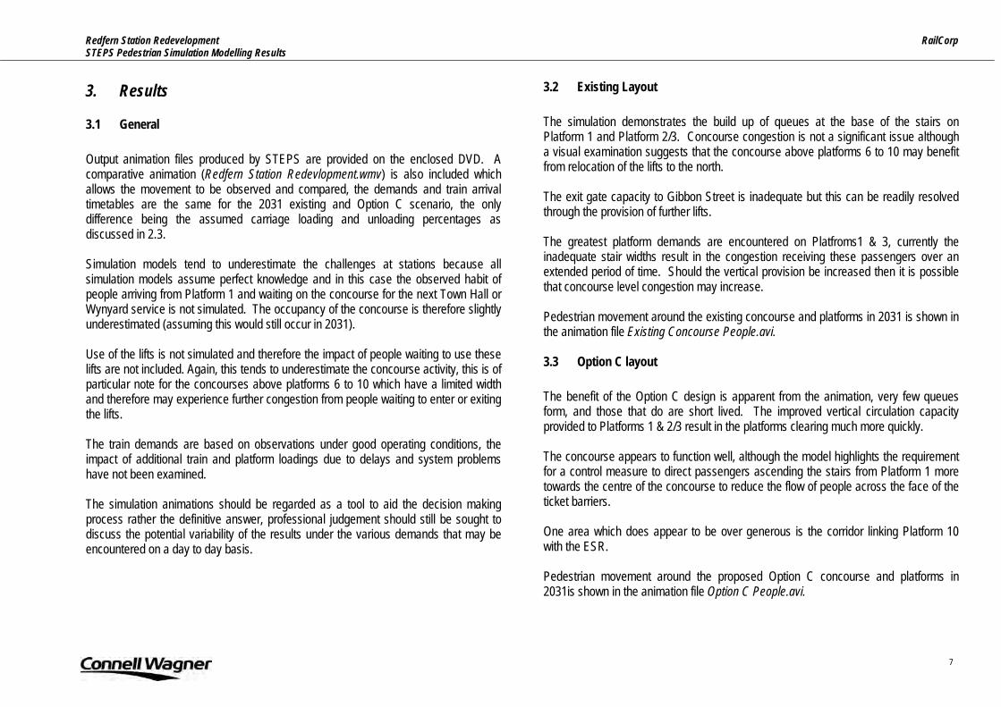
Redfern Station Redevelopment RailCorp STEPS Pedestrian Simulation Modelling Results
7
3. Results
3.1 General Output animation files produced by STEPS are provided on the enclosed DVD. A comparative animation (Redfern Station Redevlopment.wmv) is also included which allows the movement to be observed and compared, the demands and train arrival timetables are the same for the 2031 existing and Option C scenario, the only difference being the assumed carriage loading and unloading percentages as discussed in 2.3. Simulation models tend to underestimate the challenges at stations because all simulation models assume perfect knowledge and in this case the observed habit of people arriving from Platform 1 and waiting on the concourse for the next Town Hall or Wynyard service is not simulated. The occupancy of the concourse is therefore slightly underestimated (assuming this would still occur in 2031). Use of the lifts is not simulated and therefore the impact of people waiting to use these lifts are not included. Again, this tends to underestimate the concourse activity, this is of particular note for the concourses above platforms 6 to 10 which have a limited width and therefore may experience further congestion from people waiting to enter or exiting the lifts. The train demands are based on observations under good operating conditions, the impact of additional train and platform loadings due to delays and system problems have not been examined. The simulation animations should be regarded as a tool to aid the decision making process rather the definitive answer, professional judgement should still be sought to discuss the potential variability of the results under the various demands that may be encountered on a day to day basis.
3.2 Existing Layout The simulation demonstrates the build up of queues at the base of the stairs on Platform 1 and Platform 2/3. Concourse congestion is not a significant issue although a visual examination suggests that the concourse above platforms 6 to 10 may benefit from relocation of the lifts to the north. The exit gate capacity to Gibbon Street is inadequate but this can be readily resolved through the provision of further lifts. The greatest platform demands are encountered on Platfroms1 & 3, currently the inadequate stair widths result in the congestion receiving these passengers over an extended period of time. Should the vertical provision be increased then it is possible that concourse level congestion may increase. Pedestrian movement around the existing concourse and platforms in 2031 is shown in the animation file Existing Concourse People.avi. 3.3 Option C layout The benefit of the Option C design is apparent from the animation, very few queues form, and those that do are short lived. The improved vertical circulation capacity provided to Platforms 1 & 2/3 result in the platforms clearing much more quickly. The concourse appears to function well, although the model highlights the requirement for a control measure to direct passengers ascending the stairs from Platform 1 more towards the centre of the concourse to reduce the flow of people across the face of the ticket barriers. One area which does appear to be over generous is the corridor linking Platform 10 with the ESR. Pedestrian movement around the proposed Option C concourse and platforms in 2031is shown in the animation file Option C People.avi.

Redfern Station Redevelopment RailCorp STEPS Pedestrian Simulation Modelling Results
8
3.4 Summary of Results A summary of some key results are :
3.4.1 Level of Service (LOS)
LOS A/B/C D/E/F EmptyPlatform 1 Existing Stairs 6.2% 40.2% 53.7%
Option C North stairs 16.4% 14.5% 69.1%South stairs 11.1% 13.5% 75.4%
Platform 2/3 Existing 54.6% 33.2% 12.3%Option C North stairs 63.9% 24.5% 11.6%
South stairs 88.1% 0.3% 11.6% The above table summarises the Level of Service experienced over time on the stairs between the concourse and Platforms 1 & 2/3. It can be seen that not only does the Option C improvement reduce the time at which the stairs operate at LOS D/E or F (from 40.2% to 14.5% & 13.5%) but it significantly increase the time during which the stairs have no demand at all indicating an improved platform clearance time. The Option C results show slightly worse results for the Northern stairs compared to the southern stairs due to the relative location of the stairs at platform level which are not located in the exact middle of the platform. A similar improvement is observed for Platform 2/3 where the at which the stairs operate at LOS D/E or F (from 33.2% to 24.5% & 0.3%). Platform 2/3 stairs are 2way, it is evident from the animation that the platforms clear their alighting demand more quickly in Option C resulting in a reduced period of 2 way flow on the stairs – whilst not a LOS issue, this will make for a better pedestrian environment as there would be less conflict. The improvement in the level of service on the vertical circulation is also apparent from the animations (Existing Concourse LOS.avi and Option C LOS.avi) which show the actual LOS experienced by the pedestrians as they move up and down the stairs. A description of the Stair Levels of Service is provided opposite.
Key to Stairway Levels of Service
P:200480/model/Stairway Service.ppt
Stairway Level of Service A Average Flow Volume: 16.4 PMM *
Average Speed: 38.1 m/min or more
Average Pedestrian Area Occupancy: 1.9 m²/p
Unrestricted choice of speed; relatively free to pass; no serious difficulties with reverse traffic movements; flow is approximately 30% of maximum capacity.
Stairway Level of Service BAverage Flow Volume: 23 PMM
Average Speed: 36.6 m/min
Average Pedestrian Area Occupancy: 1.4 m²/p
Restricted choice of speed; passing encounters interference; reverse flows create occasional conflicts; flow is approximately 34% of maximum capacity.
Stairway Level of Service CAverage Flow Volume: 23-32.8 PMM
Average Speed: 35 m/min
Average Pedestrian Area Occupancy: 0.9 - 1.4 m²/p
Speeds are partially restricted; passing is restricted; reverse flows are partially restricted; flow is approximately 50% of maximum capacity.
Stairway Level of Service DAverage Flow Volume: 32.8-43 PMM
Average Speed: 35 m/min
Average Pedestrian Area Occupancy: 0.65 - 0.93 m²/p
Speeds are restricted; passing is virtually impossible; reverse flows are severly restricted flows are approximately 50-65 % of maximum capacity.
Stairway Level of Service EAverage Flow Volume: 42.7 - 55.8 PMM
Average Speed: 26 m/min
Average Pedestrian Area Occupancy: 0.4 m²/p
Speeds are severely restricted; passing is impossible; reverse traffic flows are severely restricted; intermittent stoppages of traffic flow are likely to occur; flows are approximately 65-85 % of maximum capacity.
Stairway Level of Service FAverage Flow Volume: 55.8 PMM or greater
Average Speed: 0-26 m/min
Average Pedestrian Area Occupancy: < 0.4 m²/p
Speed is severely restricted; flow is subject to complete breakdown with many stoppages ; passing as well as reverse flows are impossible.
Source: Planning Design & Maintenance of Pedestrian Facilities; Goodell-Grivas- 1989.
* m²/p - Square metres of walkway area per pedestrian
*PMM - Pedestrians per metre width of stairway, per minute

Redfern Station Redevelopment RailCorp STEPS Pedestrian Simulation Modelling Results
9
3.5 Emergency Evacuation Subsurface platforms represent the worst evacuation scenario and we have examined the time taken for a fully laden train (with 15% allowance for boarders) to evacuate from Platforms 11/12 for the existing and Option C layout.
3.5.1 Existing Layout Animation file Existing Concourse evacuation.avi demonstrates the evacuation from the existing ESR platforms. The passengers are assumed to all be on the platform at the start of the evacuation period which occurs 90s into the simulation. The animation file stops when the last person has left the station. The platform is cleared of passengers in 8 minutes 25 seconds and the station clears in 10 minutes 10seconds, this results falls far short of the NFPA requirement of 4minutes and 6 minutes respectively.
3.5.2 Option C Layout Animation file Option C Concourse evacuation.avi demonstrates the evacuation from the proposed Option C ESR platforms. The passengers are assumed to all be on the platform at the start of the evacuation period which occurs 90seconds into the simulation. The animation file stops when the last person has left the station. The platform is cleared of passengers in 1 minute 47 seconds and the station clears in 4 minutes 22 seconds, this compares favourably to the NFPA requirement of 4minutes and 6 minutes respectively.

Redfern Station Redevelopment RailCorp STEPS Pedestrian Simulation Modelling Results
10
4. Summary
The STEPS simulation model demonstrates and reinforces the previous analysis which concluded that the principle challenge at Redfern station is the inadequate vertical circulation from Platforms 1 & 2/3 and the non compliance of the evacuation of the ESR platforms 11/12. Simulation models tend to underestimate congestion and so should additional vertical circulation be provided at Redfern the potential subsequent impact on concourse congestion should be examined. Option C produces a visibly better solution with minimal queuing and the rapid clearance of platforms. Some minor modification could be made to the upper concourse to improve pedestrian flow and the width of the corridor between the ESR line and platform 10 could be reduced. Option C easily meets the NFPA 130 evacuation requirements.


Structural Design Philosophy Report Redfern Station Upgrade Railcorp 20 March 2007 Reference 23443 Revision 02
Connell Wagner Pty Ltd ABN 54 005 139 873 116 Military Road Neutral Bay New South Wales 2089 Australia Telephone: +61 2 9465 5599 Facsimile: +61 2 9465 5598 Email: [email protected] www.conwag.com

Document Control
Document ID: I:\23443\ENG\REPORTS\STRUCTURES\STRUCTURAL DESIGN LANDSCAPE REPORT.DOC
Rev No Date Revision Details Typist Author Verifier Approver
01 21/12/06 Issued for Information SJB SJB
02 20/03/07 SR ADL
A person using Connell Wagner documents or data accepts the risk of: a) Using the documents or data in electronic form without requesting and checking them for accuracy against the original hard copy version. b) Using the documents or data for any purpose not agreed to in writing by Connell Wagner.
Redfern Station Upgrade Railcorp Structural Design Philosophy Report
⏐ REVISION 02 ⏐ PAGE i
Contents
1. Executive Summary 1
2. Introduction 2 2.1 Design Loads 2
3. Project Risks 3 3.1 Geotechnical Information 3 3.2 Lateral Analysis of Buildings 3 3.3 Illawarra Relief (IR) Structural Information 3 3.4 Location of Engine Dive Tunnel Under Platform 1 3 3.5 Underground Services 3 3.6 Site Boundaries 3 3.7 Level of Structural Design 4
4. Station Concourse Structure 5 4.1 Foundations 5 4.2 Concourse Floor Structure 5 4.3 Roof 5 4.4 Vertical Transportation 5
5. 4 Story Building Located Over Platforms 8 to 10 6 5.1 Foundations 6 5.2 Concourse Level Transfer Structure 6 5.3 Risks Associated with Existing Structures 6 5.4 Typical Floors 6
6. 14 Story Building Located Over IR 7 6.1 Foundations 7 6.2 Basement Levels (Parking) 7 6.3 Support of the Building Over the IR 7 6.4 Typical Tower Floors 7
7. Appendix A: Structural Concept Sketches 8
Redfern Station Upgrade Railcorp Structural Design Philosophy Report
⏐ REVISION 02 ⏐ PAGE 1
1. Executive Summary
Connell Wagner were commissioned to assist with the structural engineering works associated with the masterplanning for the redevelopment of Redfern Station. Jackson Teece prepared a number of options for the site, but Option C was deemed to be the preferred option. This option was • A new paid and unpaid concourse • A new 14 storey building with 4/5 storey podium located over the Illawarra Relief • A new 4 storey building over Platform 8 to 10 Limited structural documentation exists of the structures over the IR. Connell Wagner provided two options for supporting the new buildings over the IR. The options were • Option A – new transfer truss • Option B – re-using the existing structure A concept design was prepared for the new paid and unpaid concourse. The report highlights future works that are required to future develop the design concept and identifies risks associated with the project.

Redfern Station Upgrade Railcorp Structural Design Philosophy Report
⏐ REVISION 02 ⏐ PAGE 2
2. Introduction
The redevelopment of Redfern Station is a significant project to the area and will dramatically change the function and appearance of this large piece of infrastructure. There are a number of building structures proposed: • A paid and unpaid concourse extending across the above ground platforms
linking Gibbons Street and the area near Little Eveleigh Street. • A 14 storey building over the existing Illawarra Relief (IR) with a 4/5 storey
podium along Gibbon Street. • A 4 story building over Platforms 8 to 10 adjacent to the existing Lawson Street
concourse and station masters office. Some of the risks associated with the project have been identified in Section 2 and should be incorporated in the cost assessment for the development. This report should be read in conjunction with the “Redfern Station Upgrade – Concept Design. Study Discussion Paper – Selection of Preferred Options” (dated 8/12/06) by Jackson Teece. Only Jackson Teece’s Option C has been reviewed in this report.
2.1 Design Loads The structural components have been designed in accordance with the following relevant Standards Australia codes: • AS1170.0 – Structural Design Actions Part 0: General Principles • AS1170.1 – Structural Design Actions Part 1: Permanent, Imposed and Other
Actions • AS1170.2 – Structural Design Actions Part 2: Wind Actions • AS1170.4 – Structural Design Actions Part 4: Earthquake Loads • AS3600 – Concrete Structures • AS4100 – Steel Structures • AS5100 – Bridge Design – scope and general principles
The structural components have been designed for the load allowances listed in Table 1. Refer to the architectural drawings for the proposed floor usage.
Floor Usage Live Load Super Imposed Dead Load Public Concourse 5.0 kPa 1.5 kPa
Retail 4.0 kPa 1.5 kPa Car park 3.0 kPa 0.5 kPa
Office 3.0 kPa 1.5 kPa Non-trafficable Roof 0.25 kPa 0.5 kPa
Table 1: Design Load Allowance The elements of structures exposed to the risk of train impact have been designed in accordance with Railcorp Infrastructure Engineering Standard – Structures ESC 320 clause 8.3 for an impact load of 500kN.

Redfern Station Upgrade Railcorp Structural Design Philosophy Report
⏐ REVISION 02 ⏐ PAGE 3
3. Project Risks
The risks identified for this project are generally associated with the preliminary nature of the design and the need for further site investigations. These potential costs associated with these risks must be considered in the cost estimates for the project along with potential program delays and limitations to the current architectural intent. 3.1 Geotechnical Information
No Geotechnical site investigation has been undertaken for this project. The Geotechnical information on existing structural drawings is very limit and has been the basis of the current design. The absence of Geotechnical information is considered a risk as the level of the bedrock required for pile and pad footing foundations may be lower than expected along with the quality and strength of the rock. The current structural design is based on an assumed rock bearing capacity of 3500kPa with rock located at a maximum depth of RL18 metres. 3.2 Lateral Analysis of Buildings
The global lateral stability of the buildings has not been considered in the current structural design due to the limited time available. A comprehensive lateral analysis will be undertaken as part of the detailed design phase of the project. This may result in the introduction of concrete shear walls in the building structures. An allowance in the cost plan must be made. The lateral stability of the concourse has been considered. 3.3 Illawarra Relief (IR) Structural Information
A structural survey of the existing IR tunnel and station is required to confirm the structural capacity of the existing structure to accommodate additional loads from the proposed building above. Elements requiring survey include the existing tunnel walls, existing IR building columns and footings. The survey is required to confirm the structure reflects the available existing documentation and also to determine the existing structure in areas where existing documentation is limited or not available. This survey will include local breaking out of concrete to determine reinforcement content and confirming footing sizes. This survey is outside our current scope of works.
3.4 Location of Engine Dive Tunnel Under Platform 1
An existing engine dive tunnel is located under Platform 1 within the footprint of the proposed paid and unpaid concourse. An initial review of the existing available structural documentation has revealed the location of the tunnel roof is relatively close to the Platform level and there is very limited capacity for the tunnel roof to accommodate additional vertical loads. A site survey of the dive tunnel is required to determine its exact location and therefore the areas available for concourse foundations and the Platform 1 lift pit. 3.5 Underground Services
The location of underground services is not know and may restrict the available locations of the building footings. 3.6 Site Boundaries
The exact location of the site boundary relative to the proposed building envelopes needs to be considered when locating structure close to the boundary. Gibbons Street Boundary Within the envelope of the proposed building over the IR the tunnel encroaches into Gibbons Street above. To achieve construction of the building across the IR as currently proposed would involve construction work within Gibbons Street requiring temporary partial road closure. The required approval of the relevant government body may not be achieved which needs to be considered in the risk analysis for the project. Consequence of not being able to encroach into Gibbons Street could include a reduction in the current proposed building envelope and a restriction in the available structural systems and building methods over the IR.

Redfern Station Upgrade Railcorp Structural Design Philosophy Report
⏐ REVISION 02 ⏐ PAGE 4
Platform 1 Boundary The location of the Platform 1 lift and adjacent concourse structure relative to the site boundary and nearby retaining wall and building must be determined. The existing engine tunnel limits the location of the lift within the Platform area and the exact location of the tunnel is still to be confirmed with an on-site survey. A survey of the platform has been completed but not the engine dive tunnel location. 3.7 Level of Structural Design
The current structural documentation is a concept design with only a preliminary level of analysis completed. Extensive design development is required as the architectural design of the various buildings progresses.

Redfern Station Upgrade Railcorp Structural Design Philosophy Report
⏐ REVISION 02 ⏐ PAGE 5
4. Station Concourse Structure
The station concourse consists of a paid and unpaid areas spanning across all of the rail platforms. The two concourse areas connected by an infill section over Platforms 1 to 4. 4.1 Foundations
Foundations are required for the main concourse columns, access stairs, lifts and platform awning posts. The preliminary concept design for the footings is given in sketch SK010 in Appendix A. With an assumed level of rock at approximately RL 18 metres (based on limited information documented in the IR), piles are required for all of the structural elements. The assumed pile length is 7 metres which will need to be confirmed once a Geotechnical investigation has been completed. The allowable extent of the foundations limited to areas further than 2.6metres from the platform edge due to passenger access requirements during construction. There is also a restriction for foundations located on Platform 1 due to the existing dive tunnel which cannot accommodate the required additional vertical load. The access to the platforms for construction equipment (piling rigs) must be determined. 4.2 Concourse Floor Structure
A plan of the concourse floor structure showing the preliminary concept design is given in sketch SK011 in Appendix A. The floor consists of 600mm thick precast prestressed concrete planks spanning between insitu concrete headstocks located over the platforms. The are a standard proprietary product and the maximum span of the concrete planks is 20 metres. The headstocks in the paid concourse have been designed to accommodate the central placement of the lifts while not imposing vertical load to minimise the lift wall framing. The headstocks are insitu concrete and will require formwork and falsework supported on the platform below. Once the headstocks are installed the precast planks will be lifted into place and a 150mm topping slab cast to tie the floor together. The concrete columns supporting the concourse provide lateral stability of the concourse.
4.3 Roof A steel framed roof and wall system is proposed over the paid and unpaid concourse areas. A plan of the concourse roof structure showing the preliminary concept design is given in sketch SK012 in Appendix A. There are two different roof types over the paid concourse area consisting of a standard lower flat roof separated by a higher level flat roof located over each platform. A roof truss at the interface of the different roof types provides both vertical support for the rooves along with the lateral stability of the structure. The higher level flat roof profile is continued down the stairs and along the length of the platform where it is supported by central posts. The roof structure for the unpaid concourse is also a flat roof. The support for the roof is an expressed truss which reflects the truss elements in the paid concourse roof. The vertical interfaces between the different roof structures needs further development and should be allowed for in cost estimates. Vertical bracing in the wall panels provides lateral stability along the length of the concourse while the stability across the concourse is provided by portal frame action in the main roof trusses. There is no physical connection proposed between the top of the lifts and the roof over to both reduce the load acting on the lift structure and also to provide an aesthetic gap between the two elements. 4.4 Vertical Transportation
Access from the platforms to the concourse is typically provided via a central lift and stairs at either side of the paid concourse. The lifts have been designed to be independent of the concourse floor to allow a lightweight steel framed glass box lift structure. The stairs consist of precast concrete elements for ease of installation. The alignment of the lift at Platform 1 is influenced by the location of the existing dive tunnel which needs to be confirmed with a site survey.

Redfern Station Upgrade Railcorp Structural Design Philosophy Report
⏐ REVISION 02 ⏐ PAGE 6
5. 4 Story Building Located Over Platforms 8 to 10
A new 4 story building is proposed over the northern end of Platforms 8 to 10 adjacent to the existing concourse and station masters office. The lower floor of the building is at Concourse Level and fills in the existing void bordered by Lawson Street, Gibbons Street, the IR access walkway and the existing concourse. Beyond Platform 10 the building is located over an existing railway tunnel, notated as DSS (Down Southern Suburbs) on existing documentation. 5.1 Foundations
The foundations of the building consist of piles founded on rock which is assumed to be at approximately RL 18 based on the existing IR documentation. New columns / footings are required on Platforms 7, 8, 9 and 10. Between the Platform 10 retaining wall and Gibbons Street a grid of footings at approximately 8m centres is proposed. Piles are also required under the lift pit and stair well. To maintain a regular footing grid it is preferable to locate some of the piles within the extent of the existing tunnel. The permanent disuse of the tunnel needs to be confirmed before this option is finalised. A plan of the platform showing the columns and footing location is given in sketch SK050 in Appendix A. 5.2 Concourse Level Transfer Structure
A precast floor system is proposed over the rail corridor to minimise the interference of the construction to the operation of the railway. A similar system will also be adopted over the DSS rail tunnel for ease of construction. The design of the concourse floor needs to accommodate the construction load of formwork and wet load of concrete for the floors over. A plan of the concourse showing proposed framing is given in sketch SK051 in Appendix A. 5.3 Risks Associated with Existing Structures
The following areas of risk to the project associated with interfaces with existing structure have been identified and need to be incorporated in the cost assessments:
Existing Lawson Street Concourse The partial demolition of the Lawson Street Concourse is required to accommodate the new structure. A structural review of the proposed modifications to the existing concourse framing will be required during detailed design to ensure that the load paths assumed during the original design are not dramatically altered. Additional vertical support to the existing concourse may be required to support the free edge of the existing concourse. The staging of the existing concourse demolition and new construction needs further consideration and needs to be allowed for in the cost plan and program. Existing DSS Railway Tunnel The exact location of the existing DSS railway tunnel needs to be confirmed with an on-site survey. To maintain a regular structural column grid it is preferable to locate some of the footings within the existing tunnel. The permanent disuse of the tunnel will need to be confirmed before detailed design progresses. A suspended floor structure is also required over the tunnel to avoid loading the existing tunnel roof which will add to the cost of the floor. Existing Lawson Street Road Bridge. The Lawson Street Road Bridge is adjacent to the northern end of the new building and while there is no physical connection proposed the relative movement of the two structures will need to be considered. Existing Services It is not know if there are any existing services located between the DSS tunnel and the Gibbons Street boundary. These must be identified and incorporated in the detailed design. 5.4 Typical Floors
A standard flat plate slab arrangement can be adopted and depending on the column grid spacing would be approximately 200mm thick. A plan of the typical floor showing the columns and floor structure in sketch SK052 in Appendix A.

Redfern Station Upgrade Railcorp Structural Design Philosophy Report
⏐ REVISION 02 ⏐ PAGE 7
6. 14 Story Building Located Over IR
A 14 story building wit 4/5 storey podium development along Gibbons Street is proposed in the area of the existing IR. The lower 4/5 stories extend from Platform 10 to Gibbons Street and contain Concourse and Retail Levels. The office tower extends to 14 stories with a reduced footprint. The proposed building also has basement parking levels bounded by the existing walls of the IR and Platform 10. Demolition of the existing buildings currently providing access to the underground IR is required. 6.1 Foundations
For the preliminary design the bedrock is assumed to be located at a minimum RL of 18m with a minimum bearing capacity of 3500kPa. Further Geotechnical investigation is required to confirm the rock level and properties. Between Platform 10 and the IR the columns and retaining walls are supported by new pad footings. Within the existing IR there are two options proposed to support the building over involving use of the existing vertical elements and footings. They are further discussed in section 5.3. 6.2 Basement Levels (Parking)
The basement floors consist of slab on ground at Lower Basement and a banded slab at Upper Basement. The banded slab is post-tensioned. A standard column grid of 7.8m has been adopted to suit the carpark layout and this grid is developed through to the 14 story building to avoid transfer levels. The column grid must be further investigated during the next stage of the project to optimise the construction.
6.3 Support of the Building Over the IR
The options for supporting the building over the IR have been developed to concept stage only to support the 4/5 story building component on Gibbons Street.
Option A – Transfer Truss Transfer steelwork trusses are constructed at street level to support the building columns. The trusses are 3 metres deep supported on new piles in Gibbons Street and on the new concrete wall within the new basement. It is envisaged that the truss is constructed on the existing structure, connected to the existing structure and then the IR columns removed. Options A is detailed in the attached sketch SK040 in Appendix A. Option B – Reuse of the Existing Structure The existing platform columns are retained and strengthened. The existing footings, based on the available existing documentation, can carry the additional load. This must be confirmed by intrusive investigation. A transfer level is created at street level to transfer the building grid onto the IR grid. This requires substantial works and strengthening of the existing structure. Above this level the building is conventionally constructed. Options B is detailed in the attached sketch SK041 in Appendix A. Please note the above schemes (option A and B) are conceptual only and require significant detailed design. During this design phase issues may arise that require the schemes to be changed significantly. Suitable contingencies in any cost plan need to be included. 6.4 Typical Tower Floors
The typical tower floors are banded post-tensioned slabs as shown in the floor plan on sketch SK037 in Appendix A. The slab is typically 150 thick with some deeper 180 and 200 thick slabs for the larger spans. The bands are typically 350 deep by 1800 wide bands with 200 deep by 100 wide perimeter edge beams. Again there are deeper bands required to support the larger spans in the south-east of the building. The floor over the feature clustered angled columns at the northern end of the building has been designed as a post-tensioned flat plate. The preliminary thickness of this slab is 700mm which is only approximate and will need to be confirmed during detailed design.

Redfern Station Upgrade Railcorp Structural Design Philosophy Report
⏐ REVISION 02 ⏐ PAGE 8
7. Appendix A: Structural Concept Sketches


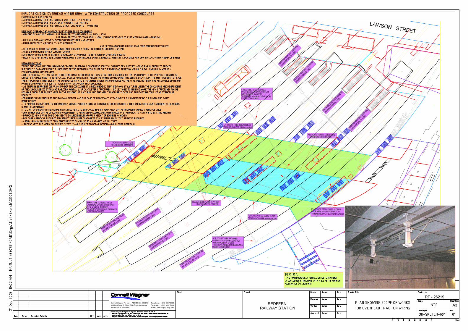


⏐ 13 JULY 2007 ⏐ PAGE 1
Signalling Concept Redfern Station Redevelopment RailCorp 13 April 2007
Connell Wagner Pty Ltd ABN 54 005 139 873 116 Military Road Neutral Bay New South Wales 2089 Australia Telephone: +61 2 9465 5599 Facsimile: +61 2 9465 5598 Email: [email protected] www.conwag.com

⏐ 13 JULY 2007 ⏐ PAGE 2
Redfern station – signalling concept. Signal SY455 Signal SY455 (pictured right) is fitted to a gantry structure between the south-west end of platforms 1 and 2 and will be impacted by the construction of a new concourse. SY455 has recently been provided to allow trains to leave Sydney Yard travelling the ‘wrong-direction’ along the Up Main. i.e. Southbound through platform 1. RailCorp have indicated that this signal is critical to the operation of Sydney Yard and as such must remain in service throughout the works at the station In order to progress this scheme Connell Wagner have considered several options: 1. Relocate SY455 approximately 20m towards Central to be clear of the new
concourse – This has the advantage that a new structure could be constructed wholly independent of the new concourse but would have a knock-on effect to adjacent signalling equipment.
2. Redesign the profile of the signal in its current location to reduce the overall
elevation. Maintenance access must be provided at all times so a clearance in the order of 2m above would still be required for an elevated walkway, alternatively access could be provided through the new concourse. In either case it is unlikely that the overall structure height could be reduced sufficiently to allow a proposed soffit at 6.1m above rail-level
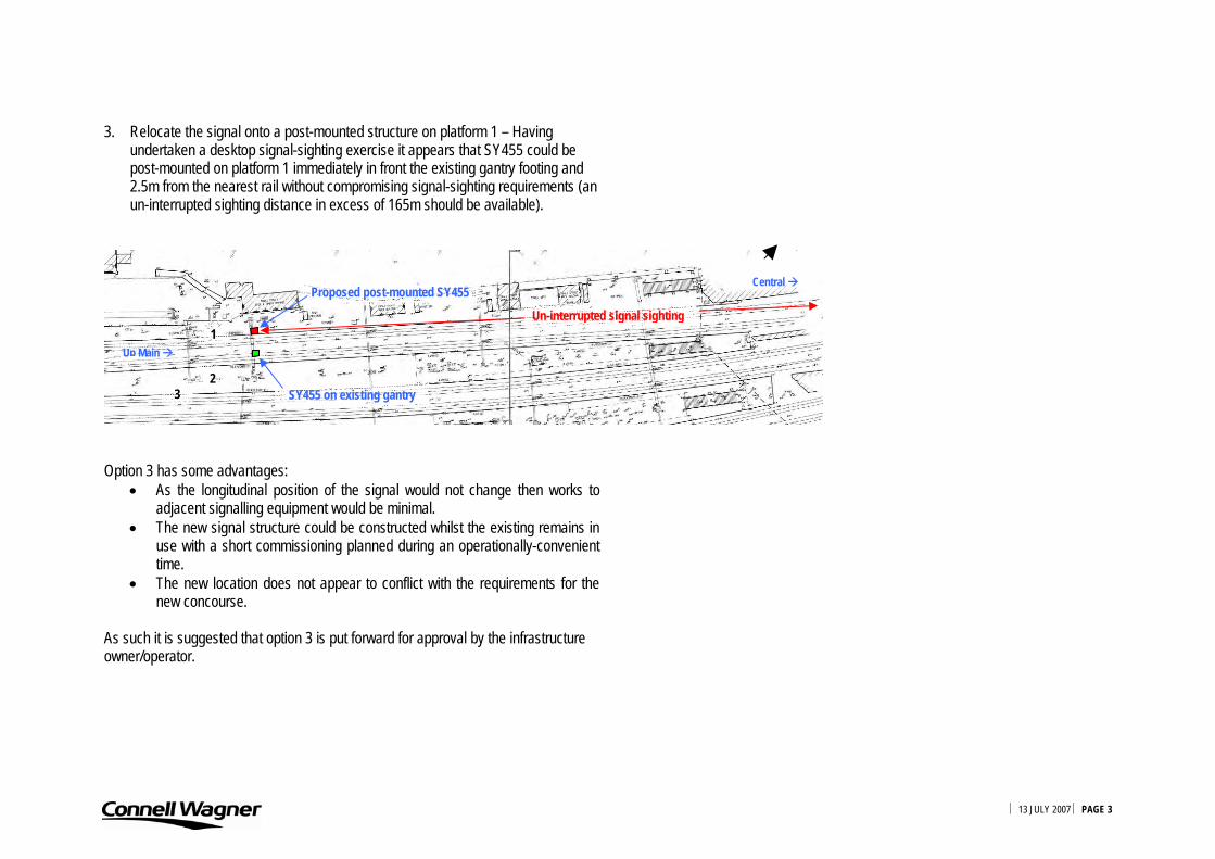
⏐ 13 JULY 2007 ⏐ PAGE 3
3. Relocate the signal onto a post-mounted structure on platform 1 – Having
undertaken a desktop signal-sighting exercise it appears that SY455 could be post-mounted on platform 1 immediately in front the existing gantry footing and 2.5m from the nearest rail without compromising signal-sighting requirements (an un-interrupted sighting distance in excess of 165m should be available).
Option 3 has some advantages:
• As the longitudinal position of the signal would not change then works to adjacent signalling equipment would be minimal.
• The new signal structure could be constructed whilst the existing remains in use with a short commissioning planned during an operationally-convenient time.
• The new location does not appear to conflict with the requirements for the new concourse.
As such it is suggested that option 3 is put forward for approval by the infrastructure owner/operator.
SY455 on existing gantry
Proposed post-mounted SY455
Un-interrupted signal sighting 1
2 3
Up Main
Central

⏐ 13 JULY 2007 ⏐ PAGE 4
Platform 9 extension It is proposed to extend platform 9 towards the road bridge to minimise passenger traffic at the narrow southwest-end of the platform. Following a site inspection of the platform-starter signal SY446 (pictured right) and associated train-stop equipment it is unlikely that the signal could be relocated more than 1m towards Central due to maintenance access requirements and the vicinity of the road bridge. Relocation to the Central side of the road bridge would result in un-acceptable signal-sighting. As such there would be little to be gained from extending platform 9 - trains would continue to stop in their present position several metres from the signal, to allow for braking tolerance and signal-sighting. Additionally, any reduction in the distance between the operational platform and the starter-signal would be at odds with RailCorp standards that state a minimum distance of 15m is desirable for new structures.
Platform 9
Platform 8

⏐ 13 JULY 2007 ⏐ PAGE 5
An alternative may be instead to extend the adjacent platform 8 approximately 5m towards Central allowing south-bound trains to stop 5m further back from the platform 8 starter-signal, SY463. Physical works would involve the construction of a new section of platform in such a manner as to allow access to the existing cable routes and minor alterations to the fencing at the south-west end of platform 8. No signalling alterations are envisaged.
Modified fencing to define new platform limits
New platform structure
8
9 8 9
SY463 Signal
6
7 6
7
Central
10