The Insider s Guide to Maintaining PROFIBUS...
21
The Insider’s Guide to Maintaining PROFIBUS Networks An introduction to common PROFIBUS problems, their location and rectification Sir William Lyons Road Warwick University Science park Coventry CV4 7EZ O2476 692066
Transcript of The Insider s Guide to Maintaining PROFIBUS...
The Insider’s Guide to
Maintaining PROFIBUS Networks
An introduction to common PROFIBUS problems, their location and rectification
Sir William Lyons Road Warwick University Science park
Coventry CV4 7EZ
O2476 692066
Maintaining PROFIBUS networks
2
Introduction Since PROFIBUS is a very mature technology none of the typical main failure modes result from a deep technical problem. Often the real problem is simply a faulty connector or rogue terminator. However finding the root of the problem on a real network can be exceptionally difficult. The fieldbus may only occasionally malfunction or errors may appear in an unrelated part of the network. Long term earthing faults may be slowly damaging network nodes creating a general distrust of the whole network. In this section I want to look at some specialist tools that make diagnosing and locating faults easy - and I do mean easy. If your production line relies on PROFIBUS you do need these tools.
Building a picture of the network
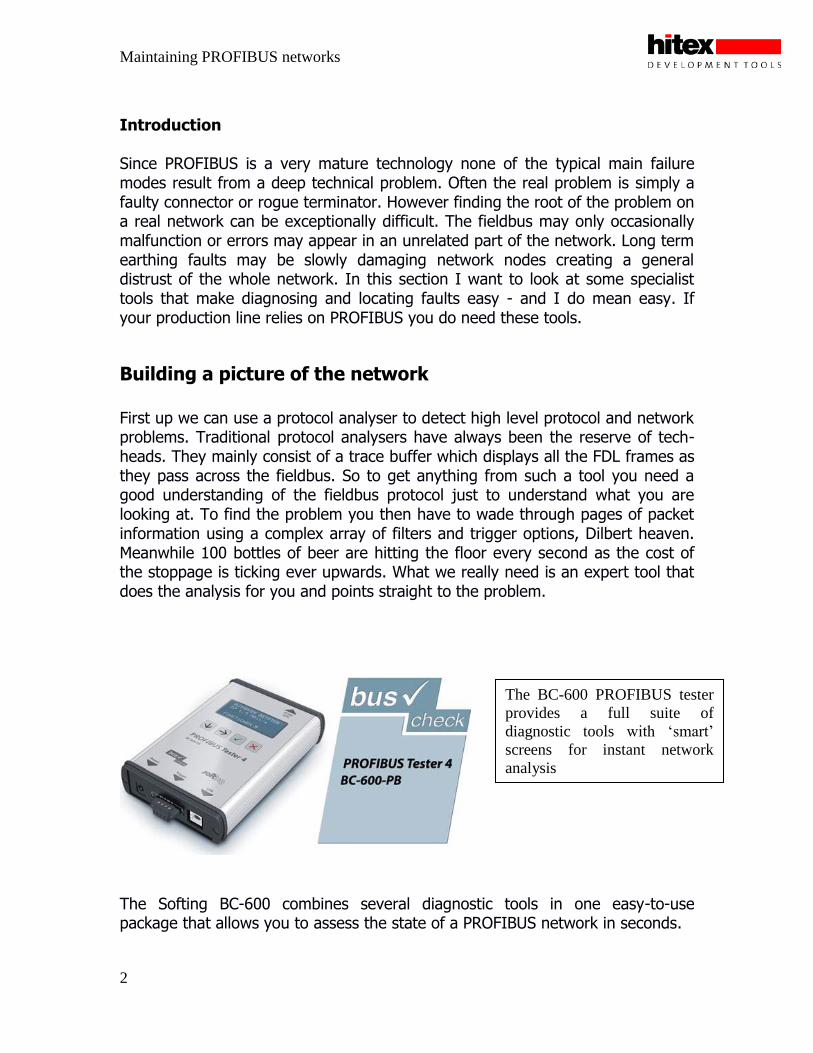
First up we can use a protocol analyser to detect high level protocol and network problems. Traditional protocol analysers have always been the reserve of tech-heads. They mainly consist of a trace buffer which displays all the FDL frames as they pass across the fieldbus. So to get anything from such a tool you need a good understanding of the fieldbus protocol just to understand what you are looking at. To find the problem you then have to wade through pages of packet information using a complex array of filters and trigger options, Dilbert heaven. Meanwhile 100 bottles of beer are hitting the floor every second as the cost of the stoppage is ticking ever upwards. What we really need is an expert tool that does the analysis for you and points straight to the problem.
The Softing BC-600 combines several diagnostic tools in one easy-to-use package that allows you to assess the state of a PROFIBUS network in seconds.
The BC-600 PROFIBUS tester
provides a full suite of
diagnostic tools with ‘smart’
screens for instant network
analysis
Maintaining PROFIBUS networks
3
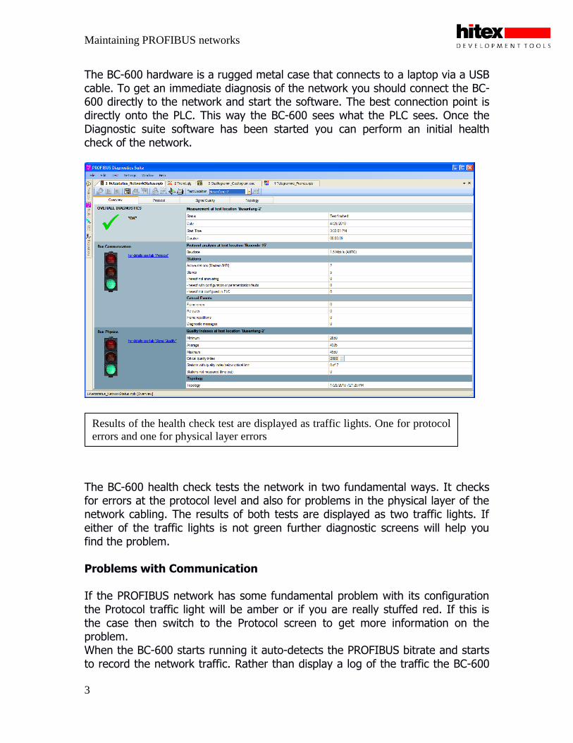
The BC-600 hardware is a rugged metal case that connects to a laptop via a USB cable. To get an immediate diagnosis of the network you should connect the BC-600 directly to the network and start the software. The best connection point is directly onto the PLC. This way the BC-600 sees what the PLC sees. Once the Diagnostic suite software has been started you can perform an initial health check of the network.
The BC-600 health check tests the network in two fundamental ways. It checks for errors at the protocol level and also for problems in the physical layer of the network cabling. The results of both tests are displayed as two traffic lights. If either of the traffic lights is not green further diagnostic screens will help you find the problem. Problems with Communication If the PROFIBUS network has some fundamental problem with its configuration the Protocol traffic light will be amber or if you are really stuffed red. If this is the case then switch to the Protocol screen to get more information on the problem. When the BC-600 starts running it auto-detects the PROFIBUS bitrate and starts to record the network traffic. Rather than display a log of the traffic the BC-600
Results of the health check test are displayed as traffic lights. One for protocol
errors and one for physical layer errors

Maintaining PROFIBUS networks
4
extracts the key network information and displays the state of all the network nodes as a live list. The live list displays all of the nodes attached to the network and their current status. The BC-600 is preconfigured with a GSD pool of many popular devices so raw network data is interpreted into meaningful messages. If a node on your network is not supported its GSD file can easily be added to the pool of devices. If a node is operating correctly it will be displayed with a green icon. If a node is connected to the fieldbus but is not actively addressed it will be displayed with a blue icon. This allows you to easily spot nodes with wrong address settings. DIP switches can be as unreliable as terminator switches so false addresses can exist even though the slave settings look correct. Finally if a node is faulty it will be displayed with a red icon. If the node misses some data exchanges it will be shown with a yellow icon to denote intermittent problems. If problems are reported they can be diagnosed with two further mouse clicks: one to select the node and a second to display the diagnosis messages.
On start up the BC-400 auto-detects the bitrate and displays the
status of each node:
Green - OK
Yellow - Intermittent problems
Blue - Address exists on network but not used by the master
Red - Faulty
Maintaining PROFIBUS networks
5
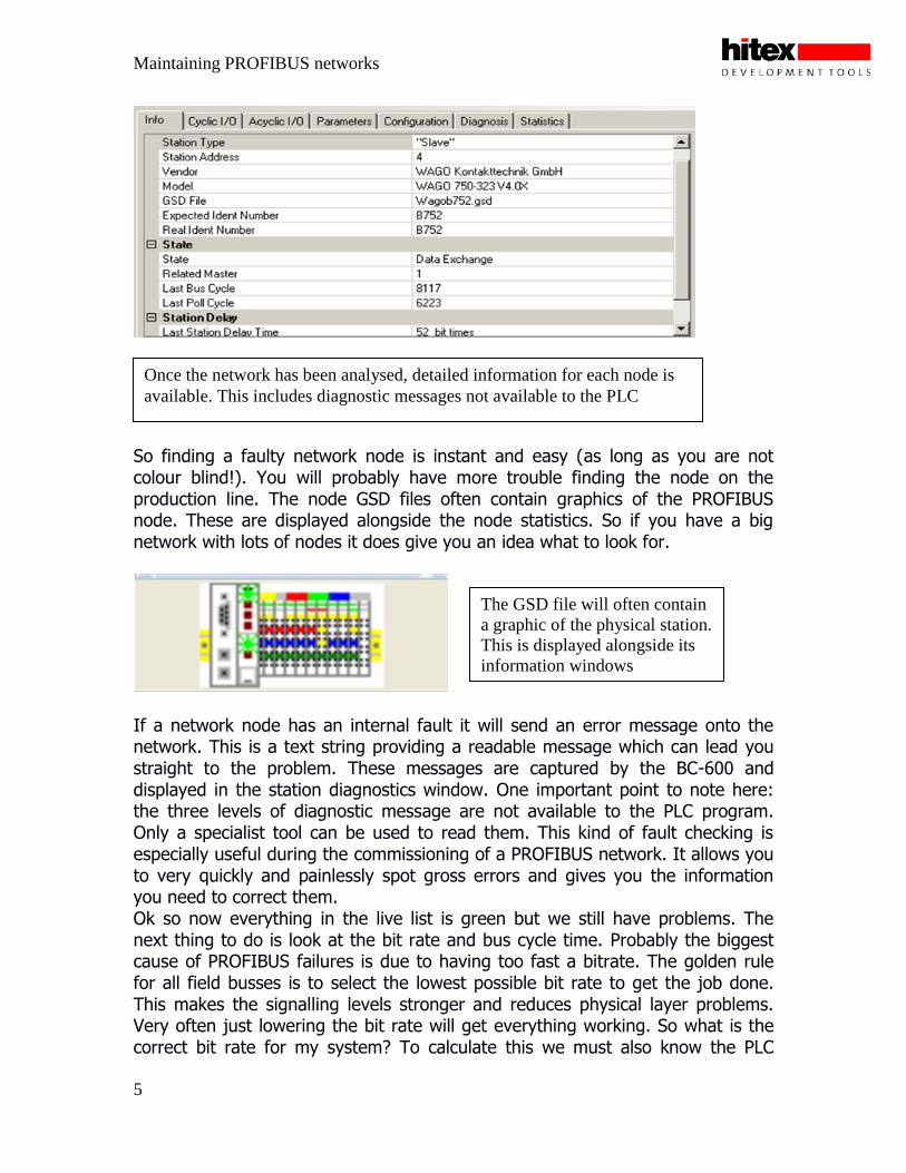
So finding a faulty network node is instant and easy (as long as you are not colour blind!). You will probably have more trouble finding the node on the production line. The node GSD files often contain graphics of the PROFIBUS node. These are displayed alongside the node statistics. So if you have a big network with lots of nodes it does give you an idea what to look for.
If a network node has an internal fault it will send an error message onto the network. This is a text string providing a readable message which can lead you straight to the problem. These messages are captured by the BC-600 and displayed in the station diagnostics window. One important point to note here: the three levels of diagnostic message are not available to the PLC program. Only a specialist tool can be used to read them. This kind of fault checking is especially useful during the commissioning of a PROFIBUS network. It allows you to very quickly and painlessly spot gross errors and gives you the information you need to correct them. Ok so now everything in the live list is green but we still have problems. The next thing to do is look at the bit rate and bus cycle time. Probably the biggest cause of PROFIBUS failures is due to having too fast a bitrate. The golden rule for all field busses is to select the lowest possible bit rate to get the job done. This makes the signalling levels stronger and reduces physical layer problems. Very often just lowering the bit rate will get everything working. So what is the correct bit rate for my system? To calculate this we must also know the PLC
Once the network has been analysed, detailed information for each node is
available. This includes diagnostic messages not available to the PLC
The GSD file will often contain
a graphic of the physical station.
This is displayed alongside its
information windows
Maintaining PROFIBUS networks
6
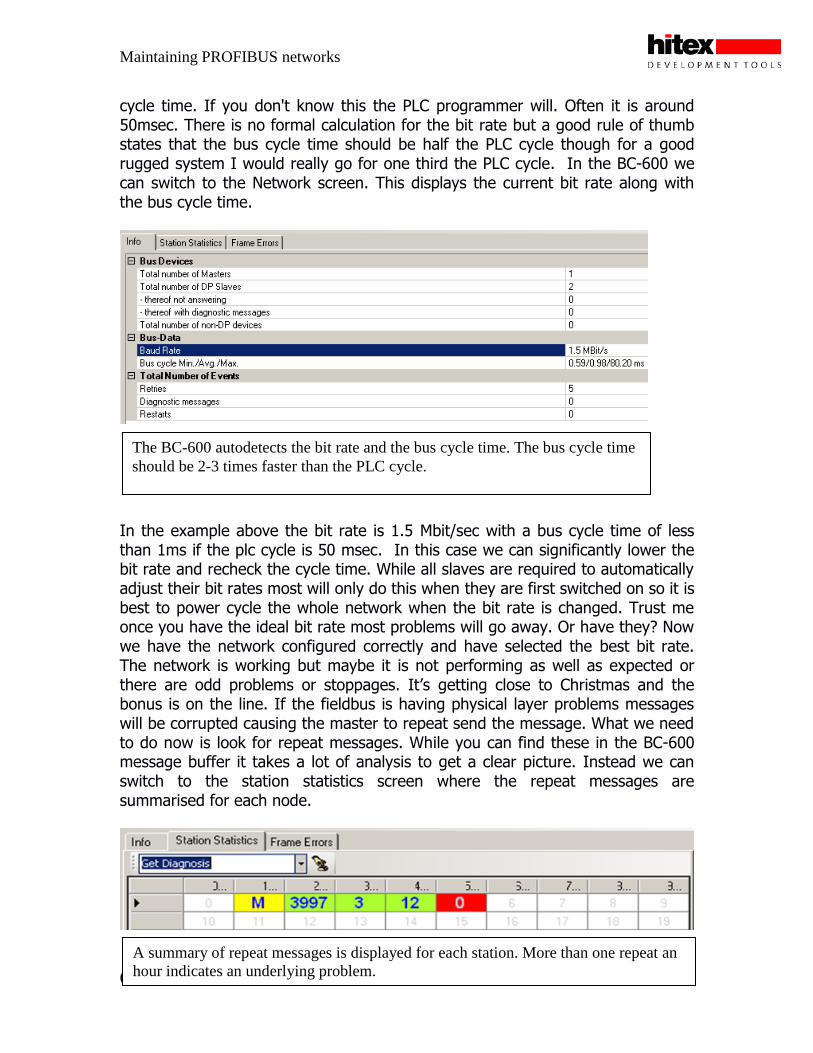
cycle time. If you don't know this the PLC programmer will. Often it is around 50msec. There is no formal calculation for the bit rate but a good rule of thumb states that the bus cycle time should be half the PLC cycle though for a good rugged system I would really go for one third the PLC cycle. In the BC-600 we can switch to the Network screen. This displays the current bit rate along with the bus cycle time.
In the example above the bit rate is 1.5 Mbit/sec with a bus cycle time of less than 1ms if the plc cycle is 50 msec. In this case we can significantly lower the bit rate and recheck the cycle time. While all slaves are required to automatically adjust their bit rates most will only do this when they are first switched on so it is best to power cycle the whole network when the bit rate is changed. Trust me once you have the ideal bit rate most problems will go away. Or have they? Now we have the network configured correctly and have selected the best bit rate. The network is working but maybe it is not performing as well as expected or there are odd problems or stoppages. It‟s getting close to Christmas and the bonus is on the line. If the fieldbus is having physical layer problems messages will be corrupted causing the master to repeat send the message. What we need to do now is look for repeat messages. While you can find these in the BC-600 message buffer it takes a lot of analysis to get a clear picture. Instead we can switch to the station statistics screen where the repeat messages are summarised for each node.
The BC-600 autodetects the bit rate and the bus cycle time. The bus cycle time
should be 2-3 times faster than the PLC cycle.
A summary of repeat messages is displayed for each station. More than one repeat an
hour indicates an underlying problem.

Maintaining PROFIBUS networks
7
Here I must be very clear: on a well-configured PROFIBUS fieldbus the number of repeat messages will be zero. Ok maybe one perhaps two per hour. If you see any repeat messages then this is a clear indication of physical layer problems. These problems are invisible to the PLC but degrade the performance of the network and will only get worse over time. So regular monitoring of the network for repeat messages is a sure-fire way to catch problems and correct problems early before they become catastrophic. Once we have detected there is a physical layer problem we need a systematic way of isolating them.
Detecting and Correcting Physical layer Problems The easiest way to detect and correct PROFIBUS physical layer problems is with a specialized line tester designed for the job. In addition to its protocol analysis features, the BC-600 includes a fully featured line tester - this is the „second traffic light‟ in the initial health check. The BC-600 line tester is designed to help you track down network problems. It can be used to find very subtle and hidden problems on the network and is the key tool to maintaining a running network. Like a multimeter or an oscilloscope it can only report what it is currently measuring and needs you to interpret the results. While this takes some skill and practice there are a few key techniques that will help you track down all common problems.
The BC-600 includes a line
tester, which is an expert tool
for PROFIBUS physical layer
problems

Maintaining PROFIBUS networks
8
Initial Calibration When you first connect to the PROFIBUS network the BC-600 will measure the idle voltage. If the bus voltage is low then the PROFIBUS network may fail to work or may work sporadically. This fault is most likely caused by an unpowered terminator. Bit Rate and Station Detection Once the BC-600 is connected to the PROFIBUS network the initial calibration screen allows you to auto-detect the bit rate and the number of stations present. The network stations can then be ordered in terms of their distance from the measuring point. Multiple test locations can also be defined, i.e. reading from different locations on the network
On connection the bus idle voltage is reported:
Red - Voltage to low
Amber - Ok but no data exchange
Green - Ok and data exchange
A failure here typically points to an unpowered
terminator
The measurement configuration screen allows you to auto detect the
network bit rate and scan for the number of stations present. Measuring
points can also be defined so you can easily record multiple
measurements

Maintaining PROFIBUS networks
9
If at this point you get a message that reads “Duplicate address found on the network” then jump ahead to the “Really really bad networks” section. First Diagnostics The BC-600 has several different diagnostic tools and we will start with the most useful. The „Signal Quality all stations‟ screen shows the signal quality of each PROFIBUS node on the network from the location measured. Always remember that what you are measuring is unique to that position on the network.
The bar graph displays the strength of the signal received from each node on a scale of 0 to 5000, representing 0-5V. While this screen indicates signal quality and not voltage the maximum PROFIBUS logic 1 signal voltage is between 3.8V and 5V. In practice you can expect a maximum reading of 4.8V or 4800 so the closer we are to this reading the better. So how do we use this tool to find problems?
The BC-600 contains several tools but the most useful shows the signal
quality for each station on the network as seen from the measuring
location
Maintaining PROFIBUS networks
10
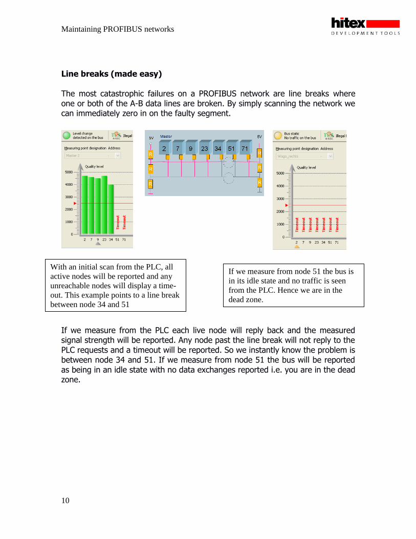
Line breaks (made easy) The most catastrophic failures on a PROFIBUS network are line breaks where one or both of the A-B data lines are broken. By simply scanning the network we can immediately zero in on the faulty segment. If we measure from the PLC each live node will reply back and the measured signal strength will be reported. Any node past the line break will not reply to the PLC requests and a timeout will be reported. So we instantly know the problem is between node 34 and 51. If we measure from node 51 the bus will be reported as being in an idle state with no data exchanges reported i.e. you are in the dead zone.
With an initial scan from the PLC, all
active nodes will be reported and any
unreachable nodes will display a time-
out. This example points to a line break
between node 34 and 51
If we measure from node 51 the bus is
in its idle state and no traffic is seen
from the PLC. Hence we are in the
dead zone.
Maintaining PROFIBUS networks
11
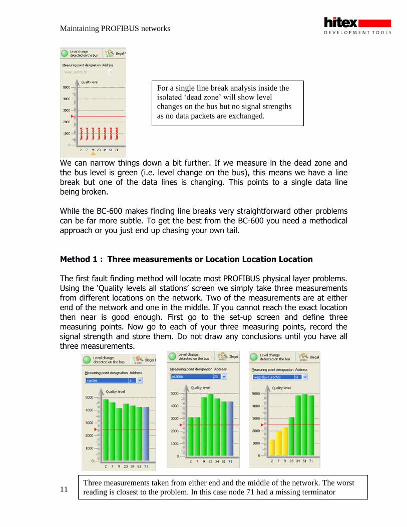
We can narrow things down a bit further. If we measure in the dead zone and the bus level is green (i.e. level change on the bus), this means we have a line break but one of the data lines is changing. This points to a single data line being broken. While the BC-600 makes finding line breaks very straightforward other problems can be far more subtle. To get the best from the BC-600 you need a methodical approach or you just end up chasing your own tail. Method 1 : Three measurements or Location Location Location The first fault finding method will locate most PROFIBUS physical layer problems. Using the „Quality levels all stations‟ screen we simply take three measurements from different locations on the network. Two of the measurements are at either end of the network and one in the middle. If you cannot reach the exact location then near is good enough. First go to the set-up screen and define three measuring points. Now go to each of your three measuring points, record the signal strength and store them. Do not draw any conclusions until you have all three measurements.
Three measurements taken from either end and the middle of the network. The worst
reading is closest to the problem. In this case node 71 had a missing terminator
For a single line break analysis inside the
isolated ‘dead zone’ will show level
changes on the bus but no signal strengths
as no data packets are exchanged.

Maintaining PROFIBUS networks
12
Once you have the three readings you can begin to locate the fault by using the following simple rule “The closer you are to the problem the worse the reading”. So simply compare the three readings and pick the one with the worst signal strengths. Next perform a measurement on either side of the worst station. If the signal improves you are going away from the problem, if it gets worse you are getting closer. As the PROFIBUS cable is the most reliable part of the whole system this simple diagnostic method will track down the rogue station. Once you have found the problem station it is a matter of inspecting the connector etc. for faults. Another characteristic shape is a gradual roll off of signal strength. This indicates that the network bit rate is too high for the length of the cable run. In this case the reading taken from the other end of the network would show a mirror image. The BC-600 has a built in master mode that allows you to manually set the bit rate. This allows you to remove the PLC from the network and rescan at lower bit rates to confirm that this cures the problem.
A roll-off in signal strength
indicates that the bit rate is too
high for the length of cable run.
Rescan from the other end of
the network and you should get
a mirror image.
The BC-600 has a built in
master mode that replaces the
PLC and allows you to test
lower bit rates and judge the
network response
Maintaining PROFIBUS networks
13
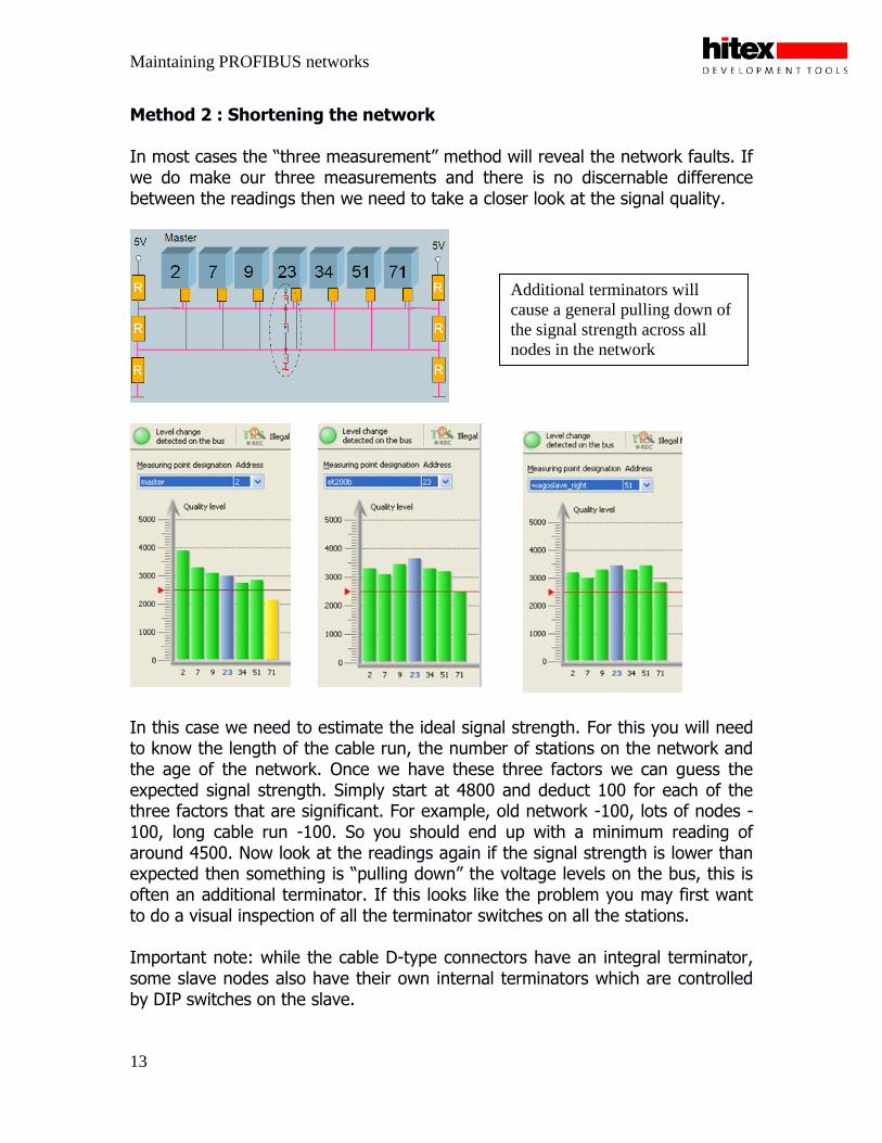
Method 2 : Shortening the network In most cases the “three measurement” method will reveal the network faults. If we do make our three measurements and there is no discernable difference between the readings then we need to take a closer look at the signal quality.
In this case we need to estimate the ideal signal strength. For this you will need to know the length of the cable run, the number of stations on the network and the age of the network. Once we have these three factors we can guess the expected signal strength. Simply start at 4800 and deduct 100 for each of the three factors that are significant. For example, old network -100, lots of nodes -100, long cable run -100. So you should end up with a minimum reading of around 4500. Now look at the readings again if the signal strength is lower than expected then something is “pulling down” the voltage levels on the bus, this is often an additional terminator. If this looks like the problem you may first want to do a visual inspection of all the terminator switches on all the stations. Important note: while the cable D-type connectors have an integral terminator, some slave nodes also have their own internal terminators which are controlled by DIP switches on the slave.
Additional terminators will
cause a general pulling down of
the signal strength across all
nodes in the network

Maintaining PROFIBUS networks
14
If this does not reveal the fault we can use the BC-600 running. If the PLC is at one end of the network as shown above then connect the BC-600 here and go to the other end of the network and the penultimate node. Here you must switch on the termination to create the new shorter network. Since the fault may be in the connector itself it is best to open the socket and disconnect the outgoing cable. Now take another reading with the BC-600. If it improves the fault is with the downstream station. If the reading stays the same move one station closer and repeat the process. When the faulty station is removed from the network the signal strengths will improve. Cable Faults As I have said before the most reliable part of a PROFIBUS system is the cable. However some systems may have moving parts which continuously flex the cable. Even cabling designed for such a system will slowly degrade until the system stops working. The PB-T3 can be used to detect the start of this failure before it becomes catastrophic. Detecting potential cable faults is really a special case of the “three measurement” test. A cable fault will produce a characteristic pattern of signal strengths.
As a cable begins to fail its resistance will
begin to rise. This produces characteristic
plots within the BC-600. This allows you to
trap the failures before the system fails.
To find additional terminators,
measure from the master and
gradually shorten the network
from the far end. When you
remove the faulty node the
network signal strength will
improve.
Maintaining PROFIBUS networks
15
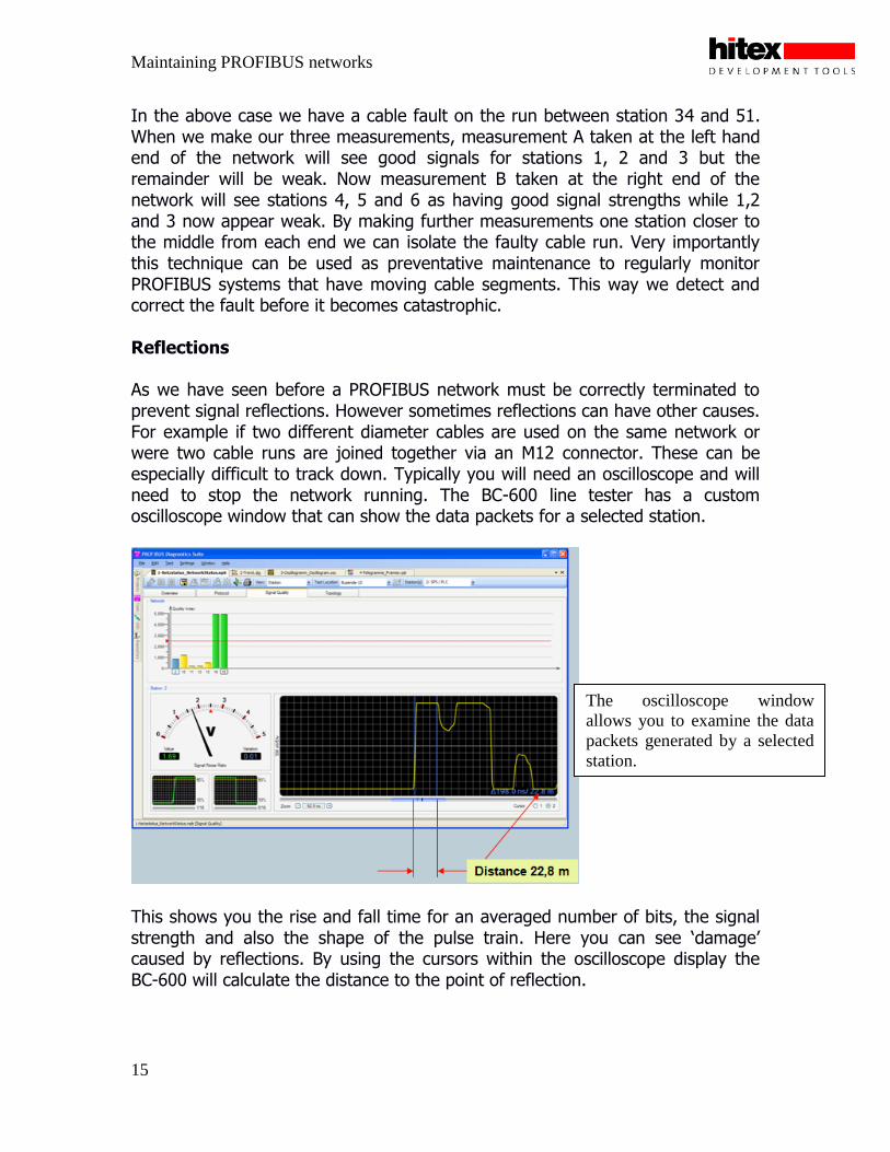
In the above case we have a cable fault on the run between station 34 and 51. When we make our three measurements, measurement A taken at the left hand end of the network will see good signals for stations 1, 2 and 3 but the remainder will be weak. Now measurement B taken at the right end of the network will see stations 4, 5 and 6 as having good signal strengths while 1,2 and 3 now appear weak. By making further measurements one station closer to the middle from each end we can isolate the faulty cable run. Very importantly this technique can be used as preventative maintenance to regularly monitor PROFIBUS systems that have moving cable segments. This way we detect and correct the fault before it becomes catastrophic. Reflections As we have seen before a PROFIBUS network must be correctly terminated to prevent signal reflections. However sometimes reflections can have other causes. For example if two different diameter cables are used on the same network or were two cable runs are joined together via an M12 connector. These can be especially difficult to track down. Typically you will need an oscilloscope and will need to stop the network running. The BC-600 line tester has a custom oscilloscope window that can show the data packets for a selected station.
This shows you the rise and fall time for an averaged number of bits, the signal strength and also the shape of the pulse train. Here you can see „damage‟ caused by reflections. By using the cursors within the oscilloscope display the BC-600 will calculate the distance to the point of reflection.
The oscilloscope window
allows you to examine the data
packets generated by a selected
station.
Maintaining PROFIBUS networks
16
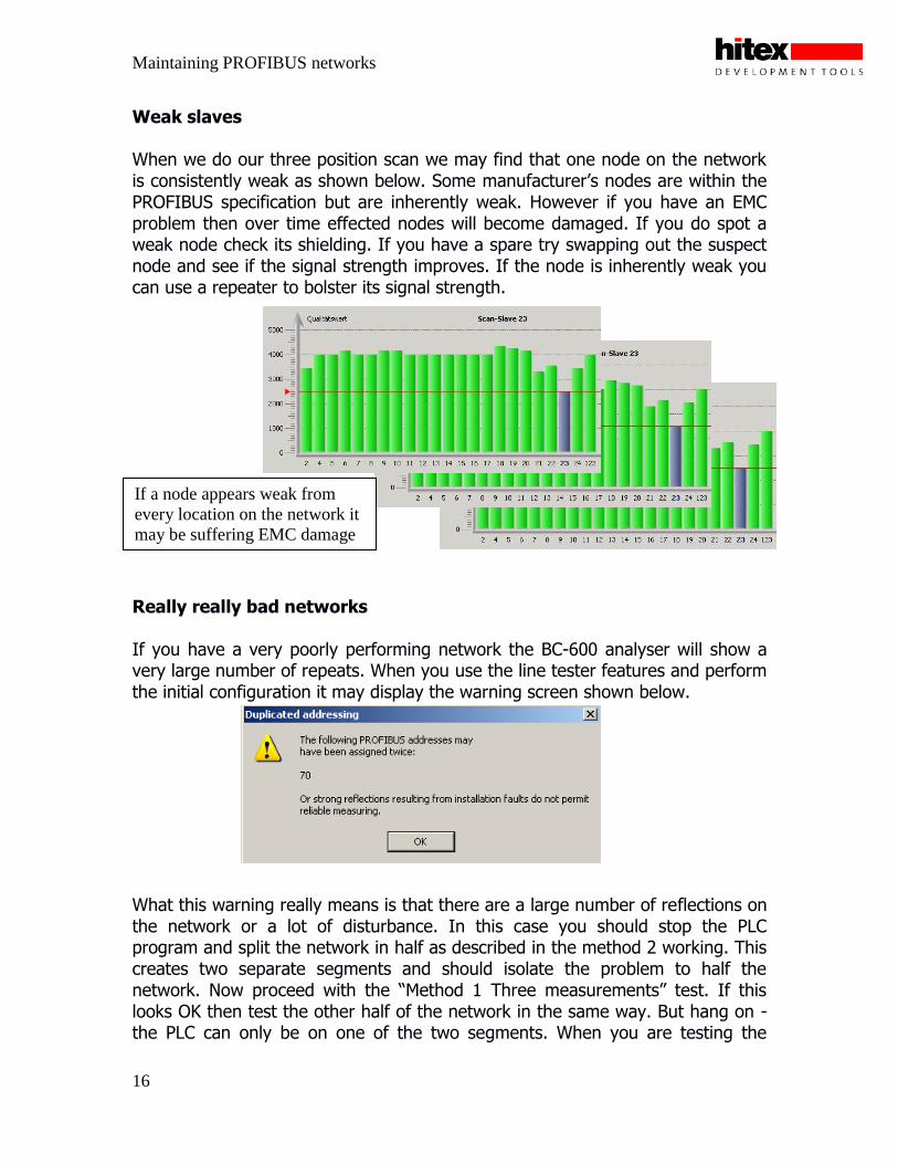
Weak slaves When we do our three position scan we may find that one node on the network is consistently weak as shown below. Some manufacturer‟s nodes are within the PROFIBUS specification but are inherently weak. However if you have an EMC problem then over time effected nodes will become damaged. If you do spot a weak node check its shielding. If you have a spare try swapping out the suspect node and see if the signal strength improves. If the node is inherently weak you can use a repeater to bolster its signal strength. Really really bad networks If you have a very poorly performing network the BC-600 analyser will show a very large number of repeats. When you use the line tester features and perform the initial configuration it may display the warning screen shown below. What this warning really means is that there are a large number of reflections on the network or a lot of disturbance. In this case you should stop the PLC program and split the network in half as described in the method 2 working. This creates two separate segments and should isolate the problem to half the network. Now proceed with the “Method 1 Three measurements” test. If this looks OK then test the other half of the network in the same way. But hang on - the PLC can only be on one of the two segments. When you are testing the
If a node appears weak from
every location on the network it
may be suffering EMC damage

Maintaining PROFIBUS networks
17
segment that does not contain the PLC there will be no PROFIBUS packets to measure. Fortunately the BC-600 has a master mode so it can duplicate the low level protocol normally generated by the PLC. This allows you to test the „dead‟ segment using our favourite “three measurements” method. Earthing problems and EMI Another common failure mode of all industrial networks is earthing problems and EMC. In a PROFIBUS network the shield must be connected to the grounding rail provided by each node. Ideally an additional earthing wire should run between each ground rail to ensure a common ground.
You can check then for any currents running in the ground shield by using a clamp meter. This is a specialist meter that will show the amount of current flowing in the PROFIBUS cable shield. The clamp meter is used to measure the in and out cable individually. If the result is zero for either cable then the shield is broken. Next we measure both cables together. If the result is greater than 10ma then the node is slowly being
A clamp meter is used to test
from damaging current levels in
the cable shield
All Industrial fieldbusses must
have good shielding to protect
the nodes from dangerous EMI

Maintaining PROFIBUS networks
18
damaged. Current running in the shield can be reduced by re-routing the cable or fitting chokes. If you have an electrically noisy environment you may get bursts of noise which cause the network to drop out. This sort of problem can be detected with both the clamp meter and the BC-600. The clamp meter has a MAX hold feature which will display the highest current reading taken. Similarly the BC-600 has a continuous measurement setting that will display the variation in signal strength over time. Leave either tool recording for a few hours and you will be able to spot any bursts of noise
The BC-600 can record the signal strength of a single station. Any EMI
disturbances are then easily spotted.

Maintaining PROFIBUS networks
19
The perfect network and keeping it that way Once you have fully analysed the field bus network your network readings should look strong and consistent from any location.
Once you have reached this happy state of affairs you can try out the topology scan feature. The topology scan will graphically display the network configuration showing each station and the distance between them.
An ideal network will show
strong signal strengths
measured from any node
The Topology scan
shows the node order
and distance between
nodes. The Topology
scan is only accurate on
a ‘perfect’ network

Maintaining PROFIBUS networks
20
The Topology scan will only give accurate results on a perfect network. So if you are feeling brave do a topology scan at one end of the network and then do a second scan at the other end. If both scans give you the same result then you do have an ideal network. Congratulations. On-going maintenance Once you have got to this happy state you will need to keep it that way. For routine preventative maintenance the BC-600 is the key tool. By regularly doing the three measurement test and the two topology scans any degradation in the network performance can be detected long before it becomes a real issue. You should also do a full network analysis when any new equipment or cable is added to the network. The BC-600 PC software can be installed on any number of PC‟s and it can be used without the BC-600 hardware attached. This allows data to be logged on the production line and emailed or otherwise transferred to the network manager for analysis. Formal certification The BC-600 also contains a flexible report generator. This facility allows you to automatically generate a comprehensive formal report based on all the data logged from the network.

Maintaining PROFIBUS networks
21
These reports can be used as part of the routine maintenance procedure or as formal certification when a new network is commissioned.
Want to know more? Further information on the Softing BUS Check tools can be found at www.softing.co.uk and www.hitex.co.uk/softing If you have any questions about the Softing BUS Check tools or would like to arrange an on-site demo please contact Trevor Martin at Hitex UK: Tel : 02476692066 Email : [email protected]