
The ideal reducer for both induction and servo motor ... · Input shaft Eccentric roller bearings...
36
The ideal reducer for both induction and servo motor applications NEW! Optional Mounting Base Matches Industry-Standard Dimensions… See Inside
Transcript of The ideal reducer for both induction and servo motor ... · Input shaft Eccentric roller bearings...
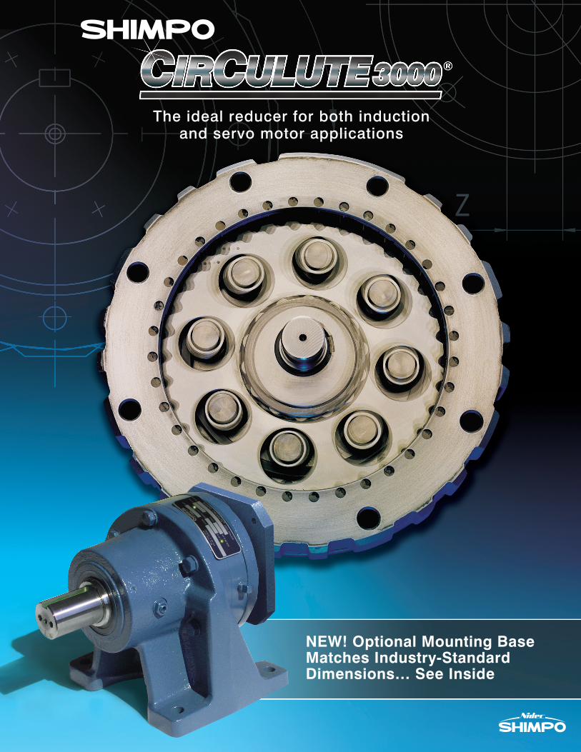
The ideal reducer for both inductionand servo motor applications
NEW! Optional Mounting Base Matches Industry-Standard Dimensions… See Inside
2 SHIMPO DRIVES, INC. / 1701 GLENLAKE AVE ITASCA IL 60143 / P: 800.842.1479 / F: 630.924.7382 / WWW.SHIMPODRIVES.COM / [email protected]
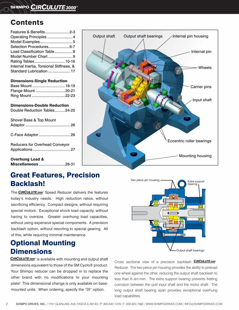
Cross sectional view of a precision backlash
Reducer. The two piece pin housing provides the ability to preload
one wheel against the other, reducing the output shaft backlash to
less than 6 arc-min. The extra support bearing prevents fretting
corrosion between the quill input shaft and the motor shaft. The
long output shaft bearing span provides exceptional overhung
load capabilities.
Features & Benefits .......................2-3Operating Principles ........................ 4Model Examples ............................... 5Selection Procedures....................6-7Load Classification Table ................. 8Model Number Chart ....................... 9Rating Tables .............................10-16Internal Inertia, Torsional Stiffness, &Standard Lubrication .....................17
Dimensions-Single ReductionBase Mount ...............................18-19Flange Mount ............................20-21Ring Mount ................................22-23
Dimensions-Double ReductionDouble Reduction Tables ..........24-25
Shovel Base & Top MountAdaptor ...........................................26
C-Face Adaptor ..............................26
Reducers for Overhead ConveyorApplications ....................................27
Overhung Load &Miscellaneous .........................28-31
Output shaft Output shaft bearings Internal pin housing
Internal pin
Wheels
Carrier pins
Input shaft
Eccentric roller bearings
Mounting housing
Contents
The Speed Reducer delivers the features
today’s industry needs. High reduction ratios, without
sacrificing efficiency. Compact designs, without requiring
special motors. Exceptional shock load capacity, without
having to oversize. Greater overhung load capacities,
without using expensive special components. A precision
backlash option, without resorting to special gearing. All
of this, while requiring minimal maintenance.
is available with mounting and output shaft
dimensions equivalent to those of the SM Cyclo® product.
Your Shimpo reducer can be dropped in to replace the
other brand with no modifications to your mounting
plate! This dimensional change is only available on base-
mounted units. When ordering, specify the “DI” option.
Great Features, PrecisionBacklash!
Optional MountingDimensions

3SHIMPO DRIVES, INC. / 1701 GLENLAKE AVE ITASCA IL 60143 / P: 800.842.1479 / F: 630.924.7382 / WWW.SHIMPODRIVES.COM / [email protected]
• Single stage reduction ratios up to 71:1 saves space
• Rolling motion minimizes friction and wear, reducing heat,
resulting in a 95% efficiency rating per stage
• 500% shock load capability as there are only compressive forces rather than shear forces on the tooth
• Low speed of cycloidal wheel results in minimal reflected inertia, less wear, and extremely long service life
• Due to the large overall “tooth / pin” contact area, select a Reducer using smaller mechanical service factors
• Standard backlash offers the highest available torque rating at an
economical price
• Precision backlash results in tighter positional tolerances
Two Backlash Ratings
Multiple Inputs: NEMA C-Face, Servo Square Flange, Shaft Input, Shovel Base, Top Mount
Straddle Mount Output Shaft Bearings(sizes D, E, F)
Features & Benefits
High Efficiency Cycloidal Reducer Design
• Supports output shaft and drive pins to provide exceptional overhung and thrust load capability, without the need for special bearings or housings
Multiple Mounting Options: Base, Flange, Ring
• Versatility to fit anywhere on your machine
• Ring style allows output bearing to extend well within the machine for greatest overhung load rating
Design Features Operational Benefits
Mounting Options
Base Mount Flange Mount Ring Mount
• Versatility to fit whatever prime mover is needed for the application
• NEMA and servo input flanges are compact “quill-style” hollow- bore configuration, eliminating input couplings and guards
• Quill-style input features an input support bearing to control fretting corrosion between motor shaft and reducer hub, and
permit tighter internal tolerances
• NEMA input flange includes threaded back-off holes for easy motor removal

4 SHIMPO DRIVES, INC. / 1701 GLENLAKE AVE ITASCA IL 60143 / P: 800.842.1479 / F: 630.924.7382 / WWW.SHIMPODRIVES.COM / [email protected]
The reduction ratio of the Speed Reducer can
be calculated using the following formula:
Operating Principles
1. When the input shaft makes one rotation, the eccentric roller
bearing also rotates once in the same direction.
2. The wheel is driven by the eccentric roller bearing.
It revolves around the internal pins with its teeth engaging with
consecutive pins.
3. When the eccentric roller bearing has completed one full rotation,
a tooth initially in mesh with a pin will be positioned
as many teeth behind its initial position as the difference between
the number of internal pins and the number of teeth.
As a result, the wheel rotates slowly in the
opposite direction of the input shaft.
4. The rotational motion of the wheel is transmitted to
the output shaft through the carrier pins.
N - MM
R =
18 - 1717R =
117 = 17:1=
R = the reduction ratio
N = the number of internal pins
M = the number of teeth
Example: N=18 and M=17,
The power t ra in sets apart from
other speed reducers.
Its main power transmission components include: an eccentric roller bearing drives a wheel around a set of internal pins, keeping rotational inertia low.
The resu l t : except iona l efficiency, long service life, and reduced wear.
5SHIMPO DRIVES, INC. / 1701 GLENLAKE AVE ITASCA IL 60143 / P: 800.842.1479 / F: 630.924.7382 / WWW.SHIMPODRIVES.COM / [email protected]
Model Examples
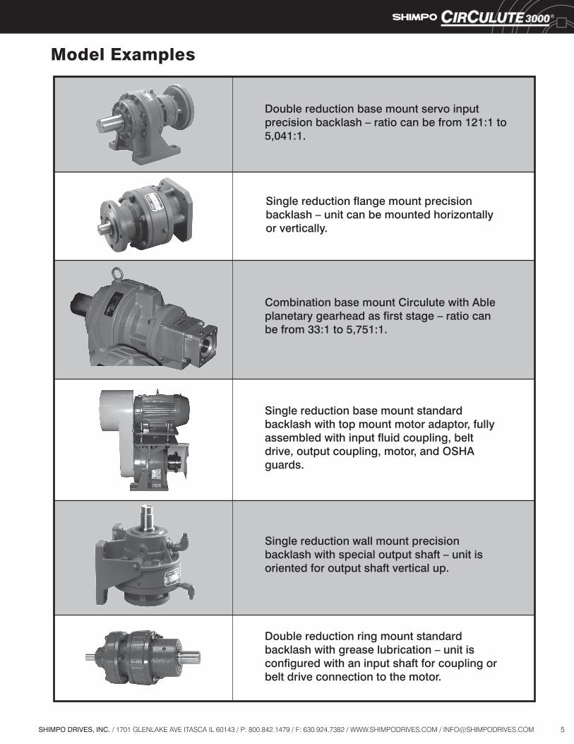
Double reduction base mount servo input precision backlash – ratio can be from 121:1 to 5,041:1.
Single reduction flange mount precision backlash – unit can be mounted horizontally or vertically.
Combination base mount Circulute with Able planetary gearhead as first stage – ratio can be from 33:1 to 5,751:1.
Single reduction base mount standard backlash with top mount motor adaptor, fully assembled with input fluid coupling, belt drive, output coupling, motor, and OSHA guards.
Double reduction ring mount standard backlash with grease lubrication – unit is configured with an input shaft for coupling or belt drive connection to the motor.
Single reduction wall mount precision backlash with special output shaft – unit is oriented for output shaft vertical up.

6 SHIMPO DRIVES, INC. / 1701 GLENLAKE AVE ITASCA IL 60143 / P: 800.842.1479 / F: 630.924.7382 / WWW.SHIMPODRIVES.COM / [email protected]
Selection Procedure for Induction Motor Applications
1. Determine the load classification from the Load Classification Table on page 8.
2. Select the Reducer service factor from the Service Factor Table (below) for the application taking into consideration the load classification, duration of service, and type of prime mover.
3. Calculate the required reduction ratio by dividing the input shaft rpm by the required output shaft rpm.
4. If selecting the reducer by HP, determine the design HP by multiplying the motor HP by the service factor. If selecting the reducer by torque, determine the design torque by multiplying the required load torque by the service factor.
5. Select the Reducer frame size from the selection tables on pages 10 - 13, making sure that the catalog rating exceeds either the design HP and/or design torque.
6. Select the required input type from page 9.
7. Select the required mounting type from page 9.
8. Select the required mounting position from page 9.
9. Check the overhung and/or thrust loads on shafts if connected to the load by either a sprocket, sheave, pulley, or gear (pages 28 - 29).
10. Configure the model number (page 9), noting any unusual operating or ambient conditions. Contact SHIMPO Drives Customer Service for questionable items, or applications assistance.
Service Factor Table
AGMA Circulute AGMA Circulute AGMA CirculuteOccasional: 1/2 hour per day 0.50 0.50 0.80 0.80 1.25 1.20
Intermittent: 3 hours per day 0.80 0.80 1.00 1.00 1.50 1.35
Up to 10 hours per day 1.00 1.00 1.25 1.20 1.75 1.50
24 hours per day 1.25 1.20 1.50 1.35 2.00 1.60
Occasional: 1/2 hour per day 0.80 0.80 1.00 1.00 1.50 1.35
Intermittent: 3 hours per day 1.00 1.00 1.25 1.20 1.75 1.50
Up to 10 hours per day 1.25 1.20 1.50 1.35 2.00 1.60
24 hours per day 1.50 1.35 1.75 1.50 2.25 1.70
Occasional: 1/2 hour per day 1.00 1.00 1.25 1.20 1.75 1.50
Intermittent: 3 hours per day 1.25 1.20 1.50 1.35 2.00 1.60
Up to 10 hours per day 1.50 1.35 1.75 1.50 2.25 1.70
24 hours per day 1.75 1.50 2.00 1.60 2.50 1.80
Note: AGMA service factors shown are the American Gear Manufacturers' recommendations for conventional gear reducers.
Electric Motor
Multi-Cylinder Internal Combustion Engine
Single Cylinder Internal Combustion Engine
Load Classification
Prime Mover Duration of Service Uniform (U) Moderate Shock (M) Heavy Shock (H)
7SHIMPO DRIVES, INC. / 1701 GLENLAKE AVE ITASCA IL 60143 / P: 800.842.1479 / F: 630.924.7382 / WWW.SHIMPODRIVES.COM / [email protected]
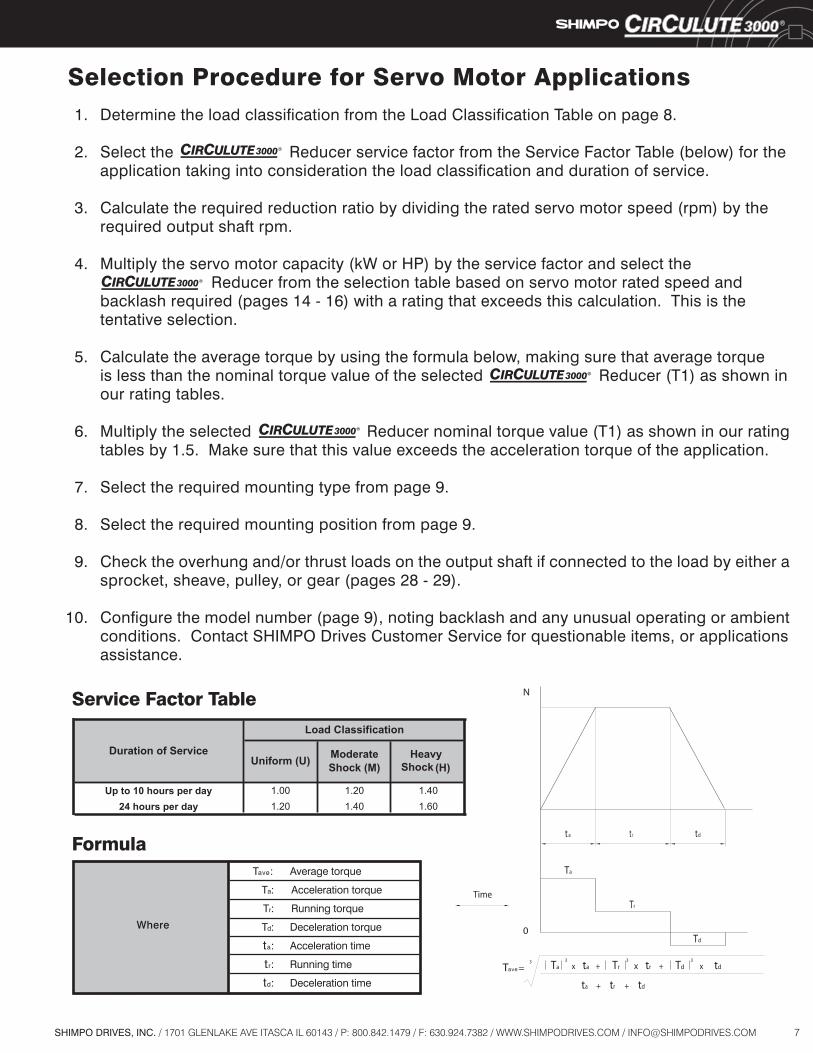
Selection Procedure for Servo Motor Applications 1. Determine the load classification from the Load Classification Table on page 8.
2. Select the Reducer service factor from the Service Factor Table (below) for the application taking into consideration the load classification and duration of service.
3. Calculate the required reduction ratio by dividing the rated servo motor speed (rpm) by the required output shaft rpm.
4. Multiply the servo motor capacity (kW or HP) by the service factor and select the Reducer from the selection table based on servo motor rated speed and backlash required (pages 14 - 16) with a rating that exceeds this calculation. This is the tentative selection.
5. Calculate the average torque by using the formula below, making sure that average torque is less than the nominal torque value of the selected Reducer (T1) as shown in our rating tables.
6. Multiply the selected Reducer nominal torque value (T1) as shown in our rating tables by 1.5. Make sure that this value exceeds the acceleration torque of the application.
7. Select the required mounting type from page 9.
8. Select the required mounting position from page 9.
9. Check the overhung and/or thrust loads on the output shaft if connected to the load by either a sprocket, sheave, pulley, or gear (pages 28 - 29).
10. Configure the model number (page 9), noting backlash and any unusual operating or ambient conditions. Contact SHIMPO Drives Customer Service for questionable items, or applications assistance.
Up to 10 hours per day 1.00 1.20 1.4024 hours per day 1.20 1.40 1.60
Duration of ServiceUniform (U) Moderate
Shock (M) HeavyShock (H)
Load Classification
Service Factor Table
Tave: Average torque
Ta: Acceleration torque
Tr: Running torque
Td: Deceleration torque
ta: Acceleration time
tr: Running time
td: Deceleration time
Formula
Where
8 SHIMPO DRIVES, INC. / 1701 GLENLAKE AVE ITASCA IL 60143 / P: 800.842.1479 / F: 630.924.7382 / WWW.SHIMPODRIVES.COM / [email protected]
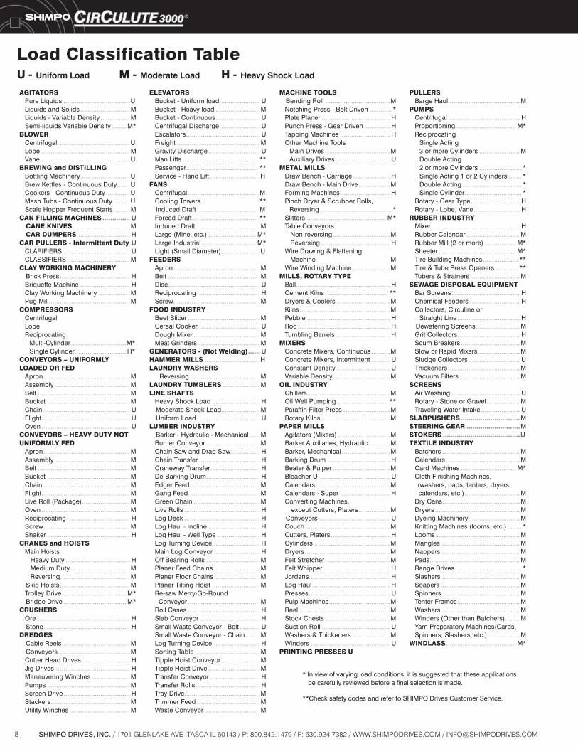
Load Classification Table
.................................... ........................... ................ ........
....................................... ................................................ .................................................
........................... .......
............. ......... .........
.............. ............................... .............................
.................................... ..................................
...................................... ........................... ................. ............................................
.............................. ............................
............................................... ......................................... .................................................. ............................................. ............................................... ................................................ ................................................
............................................... ......................................... .................................................. ............................................. ............................................... ................................................ .......................... ................................................ .................................. ............................................... .............................................
................................... ................................ ...................................... ...................................... ................................... ..................................
................................................... ...............................................
..................................... ....................................... .......................... ......................................... ..................... ............................................. .................................... ........................................... .................................
...................... ........................ ........................ ...................... ........................................ ............................................. ............................ ......................................... ....................................... ...........................
.......................................
.................................. .................................... ................................... .......................... .............................. .....................
............................................... .................................................. .................................................. .................................. ...............................................
....................................... ................................. .................................... ..................................
...... ..............................
...................................... ....................
.......................... ..................... ..................................
...... ............................. ................ ................................. ........................... ............................. ...................................... ....................................... .................................... ......................................... ......................................... ............................ ....................... .......................... ......................... ............................. ......................... ......................... .......................... ....................................... ....................................... ................................. ........... ........ .......................... ................................... ..................... ............................ ........................... ................................... ......................................... .................................. ..............................
................................... ............ ..................................... .............. ...........................
................................... ..............................
.................... ................. ...........................
....................................... ............................................
............................... ......................................
....................
................................................... .................................. ............................. ................................................. ............................................. .................................................. .............................
.......... .......... ............................. ...............................
............................................. ............................ .......................... .....................................
............................ ............ .......................... .................................. ............................... ....................................... ........................................ ...........................
................. ....................................... .............................................. ................................ ......................................... .............................................. ................................... .................................... ............................................ .......................................... ............................................ ................................. ................................................. ................................... ..................................... ..................... ...........................................
.......................................
....................................... ................................. ...................... ....................... ....... ................................ ............................... .......................... .........................
................................................ ............................. ................. .......................................... ................... ............ ...........................
..................................... ...........................
.................................. ........................ .................................. ................................ ....................... ............................ ....................................... .................................
..................................... .................. .....................
.............................. ...........................
.......................................
.......................................... ........................................ ..............................
.............................. .......................................... .............................................. ............................ ........ .............................................. ........................................... ........................................... ................................................. .................................... ........................................... ........................................... .......................................... .................................. ........................................... ........ .................
......................................
U - Uniform Load M - Moderate Load H - Heavy Shock Load
* In view of varying load conditions, it is suggested that these applications be carefully reviewed before a final selection is made.
**Check safety codes and refer to SHIMPO Drives Customer Service.
AGITATORS Pure Liquids U Liquids and Solids M Liquids - Variable Density M Semi-liquids Variable Density M*BLOWER Centrifugal U Lobe M Vane UBREWING and DISTILLING Bottling Machinery U Brew Kettles - Continuous Duty U Cookers - Continuous Duty U Mash Tubs - Continuous Duty U Scale Hopper Frequent Starts MCAN FILLING MACHINES U CANE KNIVES M CAR DUMPERS HCAR PULLERS - Intermittent Duty U CLARIFIERS U CLASSIFIERS MCLAY WORKING MACHINERY Brick Press H Briquette Machine H Clay Working Machinery M Pug Mill MCOMPRESSORS Centrifugal Lobe Reciprocating Multi-Cylinder M* Single Cylinder H*CONVEYORS – UNIFORMLYLOADED OR FED Apron M Assembly M Belt M Bucket M Chain U Flight U Oven UCONVEYORS – HEAVY DUTY NOTUNIFORMLY FED Apron M Assembly M Belt M Bucket M Chain M Flight M Live Roll (Package) M Oven M Reciprocating H Screw M Shaker HCRANES and HOISTS Main Hoists Heavy Duty H Medium Duty M Reversing M Skip Hoists M Trolley Drive M* Bridge Drive M*CRUSHERS Ore H Stone HDREDGES Cable Reels M Conveyors M Cutter Head Drives H Jig Drives H Maneuvering Winches M Pumps M Screen Drive H Stackers M Utility Winches M
ELEVATORS Bucket - Uniform load U Bucket - Heavy load M Bucket - Continuous U Centrifugal Discharge U Escalators U Freight M Gravity Discharge U Man Lifts ** Passenger ** Service - Hand Lift HFANS Centrifugal M Cooling Towers ** Induced Draft M Forced Draft ** Induced Draft M Large (Mine, etc.) M* Large Industrial M* Light (Small Diameter) UFEEDERS Apron M Belt M Disc U Reciprocating H Screw MFOOD INDUSTRY Beet Slicer M Cereal Cooker U Dough Mixer M Meat Grinders MGENERATORS - (Not Welding) UHAMMER MILLS HLAUNDRY WASHERS Reversing MLAUNDRY TUMBLERS MLINE SHAFTS Heavy Shock Load H Moderate Shock Load M Uniform Load ULUMBER INDUSTRY Barker - Hydraulic - Mechanical M Burner Conveyor M Chain Saw and Drag Saw H Chain Transfer H Craneway Transfer H De-Barking Drum H Edger Feed M Gang Feed M Green Chain M Live Rolls H Log Deck H Log Haul - Incline H Log Haul - Well Type H Log Turning Device H Main Log Conveyor H Off Bearing Rolls M Planer Feed Chains M Planer Floor Chains M Planer Tilting Hoist M Re-saw Merry-Go-Round Conveyor M Roll Cases H Slab Conveyor H Small Waste Conveyor - Belt U Small Waste Conveyor - Chain M Log Turning Device H Sorting Table M Tipple Hoist Conveyor M Tipple Hoist Drive M Transfer Conveyor H Transfer Rolls H Tray Drive M Trimmer Feed M Waste Conveyor M
MACHINE TOOLS Bending Roll M Notching Press - Belt Driven * Plate Planer H Punch Press - Gear Driven H Tapping Machines H Other Machine Tools Main Drives M Auxiliary Drives UMETAL MILLS Draw Bench - Carriage H Draw Bench - Main Drive M Forming Machines H Pinch Dryer & Scrubber Rolls, Reversing * Slitters M* Table Conveyors Non-reversing M Reversing H Wire Drawing & Flattening Machine M Wire Winding Machine MMILLS, ROTARY TYPE Ball H Cement Kilns ** Dryers & Coolers M Kilns M Pebble H Rod H Tumbling Barrels HMIXERS Concrete Mixers, Continuous M Concrete Mixers, Intermittent U Constant Density U Variable Density MOIL INDUSTRY Chillers M Oil Well Pumping ** Paraffin Filter Press M Rotary Kilns M PAPER MILLS Agitators (Mixers) M Barker Auxiliaries, Hydraulic M Barker, Mechanical M Barking Drum H Beater & Pulper M Bleacher U U Calendars M Calendars - Super H Converting Machines, except Cutters, Platers M Conveyors U Couch M Cutters, Platers H Cylinders M Dryers M Felt Stretcher M Felt Whipper H Jordans H Log Haul H Presses U Pulp Machines M Reel M Stock Chests M Suction Roll U Washers & Thickeners M Winders UPRINTING PRESSES U
PULLERS Barge Haul MPUMPS Centrifugal H Proportioning M* Reciprocating Single Acting 3 or more Cylinders M Double Acting 2 or more Cylinders * Single Acting 1 or 2 Cylinders * Double Acting * Single Cylinder * Rotary - Gear Type H Rotary - Lobe, Vane HRUBBER INDUSTRY Mixer H Rubber Calendar M Rubber Mill (2 or more) M* Sheeter M* Tire Building Machines ** Tire & Tube Press Openers ** Tubers & Strainers MSEWAGE DISPOSAL EQUIPMENT Bar Screens H Chemical Feeders H Collectors, Circuline or Straight Line H Dewatering Screens M Grit Collectors H Scum Breakers M Slow or Rapid Mixers M Sludge Collectors U Thickeners M Vacuum Filters MSCREENS Air Washing U Rotary - Stone or Gravel M Traveling Water Intake USLABPUSHERS MSTEERING GEAR MSTOKERS UTEXTILE INDUSTRY Batchers M Calendars M Card Machines M* Cloth Finishing Machines, (washers, pads, tenters, dryers, calendars, etc.) M Dry Cans M Dryers M Dyeing Machinery M Knitting Machines (looms, etc.) * Looms M Mangles M Nappers M Pads M Range Drives * Slashers M Soapers M Spinners M Tenter Frames M Washers M Winders (Other than Batchers) M Yarn Preparatory Machines(Cards, Spinners, Slashers, etc.) MWINDLASS M*
9SHIMPO DRIVES, INC. / 1701 GLENLAKE AVE ITASCA IL 60143 / P: 800.842.1479 / F: 630.924.7382 / WWW.SHIMPODRIVES.COM / [email protected]
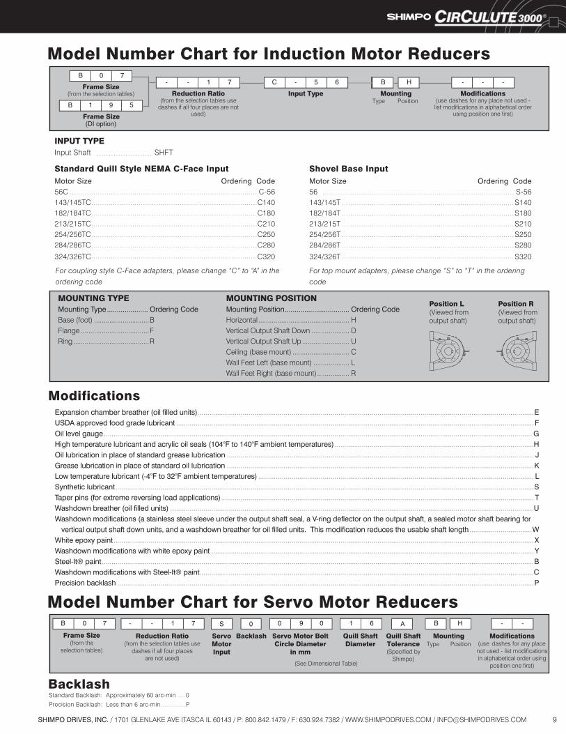
Model Number Chart for Induction Motor Reducers
MOUNTING TYPEMounting Type ..................... Ordering CodeBase (foot) .............................BFlange ....................................FRing ........................................R
.......................
Shovel Base Input
MOUNTING POSITIONMounting Position ................................. Ordering CodeHorizontal ................................................ H Vertical Output Shaft Down .................... DVertical Output Shaft Up ......................... UCeiling (base mount) .............................. C Wall Feet Left (base mount) ................... L Wall Feet Right (base mount) ................. R
Position L(Viewed from output shaft)
Position R(Viewed from output shaft)
For coupling style C-Face adapters, please change “C” to “A” in the
ordering codeFor top mount adapters, please change “S” to “T” in the ordering
code
......................................................................................... ................................................................................ ................................................................................ ................................................................................ ................................................................................ ................................................................................ ................................................................................
....................................................................................... ............................................................................. ............................................................................. ............................................................................. ............................................................................. ............................................................................. .............................................................................
............................................................................................................................................................................ .......................................................................................................................................................................................
........................................................................................................................................................................................................................... ......................................................................................................
............................................................................................................................................................. .............................................................................................................................................................
............................................................................................................................................. ......................................................................................................................................................................................................................
................................................................................................................................................................ ..........................................................................................................................................................................................
.................................. .......................................................................................................................................................................................................................
..................................................................................................................................................................... .............................................................................................................................................................................................................................
........................................................................................................................................................................... .....................................................................................................................................................................................................................
Model Number Chart for Servo Motor Reducers
Standard Quill Style NEMA C-Face Input
Modifications
INPUT TYPEInput Shaft SHFT
Motor Size Ordering Code56C C-56143/145TC C140182/184TC C180213/215TC C210254/256TC C250284/286TC C280
324/326TC C320
Motor Size Ordering Code56 S-56143/145T S140182/184T S180213/215T S210254/256T S250284/286T S280
324/326T S320
.....
..............
BacklashStandard Backlash: Approximately 60 arc-min 0
Precision Backlash: Less than 6 arc-min P
Expansion chamber breather (oil filled units) EUSDA approved food grade lubricant FOil level gauge GHigh temperature lubricant and acrylic oil seals (104°F to 140°F ambient temperatures) HOil lubrication in place of standard grease lubrication JGrease lubrication in place of standard oil lubrication KLow temperature lubricant (-4°F to 32°F ambient temperatures) LSynthetic lubricant STaper pins (for extreme reversing load applications) TWashdown breather (oil filled units) UWashdown modifications (a stainless steel sleeve under the output shaft seal, a V-ring deflector on the output shaft, a sealed motor shaft bearing for vertical output shaft down units, and a washdown breather for oil filled units. This modification reduces the usable shaft length WWhite epoxy paint XWashdown modifications with white epoxy paint YSteel-It® paint BWashdown modifications with Steel-It® paint CPrecision backlash P

10 SHIMPO DRIVES, INC. / 1701 GLENLAKE AVE ITASCA IL 60143 / P: 800.842.1479 / F: 630.924.7382 / WWW.SHIMPODRIVES.COM / [email protected]
Rating Table 1750 rpm Input, Single Reduction, Standard Backlash
Ratio 11 17 29 35 47 59 71
Output rpm 159 103 60.3 50.0 37.2 29.7 24.6
Input HP 1.03 0.93 0.58 0.53 0.37 0.28 0.19Output lb-in 377 523 556 612 580 552 439
Input HP 1.22 1.09 0.68 0.62 0.44 0.33 0.22Output lb-in 443 615 654 720 682 649 517
Input HP 1.43 1.29 0.80 0.73 0.52 0.39 0.26Output lb-in 521 724 769 847 802 764 608
Input HP 2.17 1.53 1.08 0.86 0.61 0.48 0.39Output lb-in 790 860 1,040 1,000 950 940 910
Input HP 2.72 1.92 1.35 1.08 0.76 0.60 0.48Output lb-in 990 1,080 1,300 1,250 1,190 1,170 1,140
Input HP 3.40 2.40 1.70 1.35 0.96 0.75 0.60Output lb-in 1,240 1,350 1,630 1,560 1,490 1,460 1,420
Input HP 4.25 3.00 2.12 1.68 1.19 0.93 0.75Output lb-in 1,550 1,690 2,040 1,950 1,860 1,820 1,770
Input HP 5.02 3.87 2.41 2.22 1.53 1.22 1.02Output lb-in 1,830 2,180 2,320 2,570 2,390 2,390 2,390
Input HP 6.28 4.83 3.02 2.77 1.92 1.53 1.27Output lb-in 2,290 2,720 2,900 3,210 2,990 2,990 2,990
Input HP 7.38 6.43 4.02 3.69 2.56 2.04 1.69Output lb-in 2,690 3,620 3,860 4,280 3,990 3,990 3,980
Input HP 8.67 8.02 5.03 4.61 3.20 2.55 2.12Output lb-in 3,160 4,520 4,830 5,350 4,990 4,990 4,980
Input HP 10.4 9.84 6.21 5.50 4.10 3.15 2.50Output lb-in 3,800 5,540 5,970 6,380 6,380 6,150 5,870
Input HP 13.0 11.6 7.31 6.48 4.82 3.70 2.94Output lb-in 4,750 6,520 7,020 7,510 7,510 7,230 6,910
Input HP 16.3 13.6 8.60 7.62 5.68 4.35 3.46Output lb-in 5,940 7,670 8,260 8,840 8,840 8,500 8,130
Input HP 20.4 16.0 10.1 8.97 6.68 5.12 4.06Output lb-in 7,420 9,020 9,720 10,400 10,400 10,000 9,560
Input HP 24.0 18.8 13.9 11.6 7.71 6.34 4.93Output lb-in 8,730 10,600 13,400 13,400 12,000 12,400 11,600
Input HP 26.6 22.2 18.5 15.3 10.3 8.44 6.55Output lb-in 9,700 12,500 17,800 17,800 16,000 16,500 15,400
Input HP 31.3 27.7 23.1 19.1 12.8 10.5 8.16Output lb-in 11,400 15,600 22,200 22,200 20,000 20,600 19,200
Input HP 39.0 34.6 28.9 24.0 16.1 13.2 10.2Output lb-in 14,200 19,500 27,800 27,800 25,000 25,800 24,000
Input HP 45.8 40.3 34.4 30.1 21.8 16.6 13.8Output lb-in 16,700 22,700 33,100 34,900 34,000 32,400 32,400
Input HP 51.0 47.4 40.5 35.4 25.7 19.5 16.2Output lb-in 18,600 26,700 38,900 41,000 40,000 38,100 38,100
Input HP 60.1 59.3 50.6 44.2 32.1 24.3 20.2Output lb-in 21,900 33,400 48,600 51,200 50,000 47,600 47,600
Notes:Backlash specification is approximately 1o (60 arc-min).
B03B100
B05B105
A07A195
C03C110
C05C115
D05D145
ReducerFrame Size
C07C225
C01
D01
A03
A05A190
B07B20H
B01B197
D03D135
D07D255
F07
E01
E03E165
E05E370
E07E375
F03
F05
11SHIMPO DRIVES, INC. / 1701 GLENLAKE AVE ITASCA IL 60143 / P: 800.842.1479 / F: 630.924.7382 / WWW.SHIMPODRIVES.COM / [email protected]
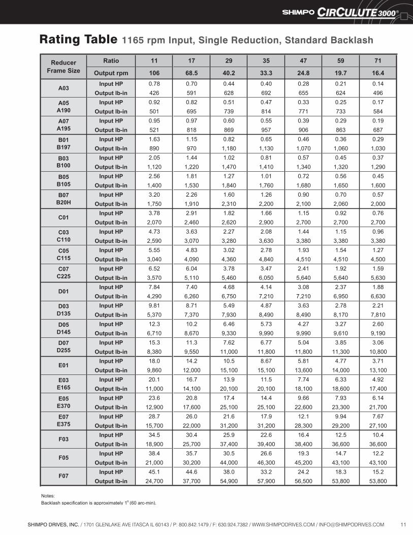
Rating Table 1165 rpm Input, Single Reduction, Standard Backlash
Ratio 11 17 29 35 47 59 71
Output rpm 106 68.5 40.2 33.3 24.8 19.7 16.4Input HP 0.78 0.70 0.44 0.40 0.28 0.21 0.14
Output lb-in 426 591 628 692 655 624 496Input HP 0.92 0.82 0.51 0.47 0.33 0.25 0.17
Output lb-in 501 695 739 814 771 733 584Input HP 0.95 0.97 0.60 0.55 0.39 0.29 0.19
Output lb-in 521 818 869 957 906 863 687Input HP 1.63 1.15 0.82 0.65 0.46 0.36 0.29
Output lb-in 890 970 1,180 1,130 1,070 1,060 1,030Input HP 2.05 1.44 1.02 0.81 0.57 0.45 0.37
Output lb-in 1,120 1,220 1,470 1,410 1,340 1,320 1,290Input HP 2.56 1.81 1.27 1.01 0.72 0.56 0.45
Output lb-in 1,400 1,530 1,840 1,760 1,680 1,650 1,600Input HP 3.20 2.26 1.60 1.26 0.90 0.70 0.57
Output lb-in 1,750 1,910 2,310 2,200 2,100 2,060 2,000Input HP 3.78 2.91 1.82 1.66 1.15 0.92 0.76
Output lb-in 2,070 2,460 2,620 2,900 2,700 2,700 2,700Input HP 4.73 3.63 2.27 2.08 1.44 1.15 0.96
Output lb-in 2,590 3,070 3,280 3,630 3,380 3,380 3,380Input HP 5.55 4.83 3.02 2.78 1.93 1.54 1.27
Output lb-in 3,040 4,090 4,360 4,840 4,510 4,510 4,500Input HP 6.52 6.04 3.78 3.47 2.41 1.92 1.59
Output lb-in 3,570 5,110 5,460 6,050 5,640 5,640 5,630Input HP 7.84 7.40 4.68 4.14 3.08 2.37 1.88
Output lb-in 4,290 6,260 6,750 7,210 7,210 6,950 6,630Input HP 9.81 8.71 5.49 4.87 3.63 2.78 2.21
Output lb-in 5,370 7,370 7,930 8,490 8,490 8,170 7,810Input HP 12.3 10.2 6.46 5.73 4.27 3.27 2.60
Output lb-in 6,710 8,670 9,330 9,990 9,990 9,610 9,190Input HP 15.3 11.3 7.62 6.77 5.04 3.85 3.06
Output lb-in 8,380 9,550 11,000 11,800 11,800 11,300 10,800Input HP 18.0 14.2 10.5 8.67 5.81 4.77 3.71
Output lb-in 9,860 12,000 15,100 15,100 13,600 14,000 13,100Input HP 20.1 16.7 13.9 11.5 7.74 6.33 4.92
Output lb-in 11,000 14,100 20,100 20,100 18,100 18,600 17,400Input HP 23.6 20.8 17.4 14.4 9.66 7.93 6.14
Output lb-in 12,900 17,600 25,100 25,100 22,600 23,300 21,700Input HP 28.7 26.0 21.6 17.9 12.1 9.94 7.67
Output lb-in 15,700 22,000 31,200 31,200 28,300 29,200 27,100Input HP 34.5 30.4 25.9 22.6 16.4 12.5 10.4
Output lb-in 18,900 25,700 37,400 39,400 38,400 36,600 36,600Input HP 38.4 35.7 30.5 26.6 19.3 14.7 12.2
Output lb-in 21,000 30,200 44,000 46,300 45,200 43,100 43,100Input HP 45.1 44.6 38.0 33.2 24.2 18.3 15.2
Output lb-in 24,700 37,700 54,900 57,900 56,500 53,800 53,800
Notes:Backlash specification is approximately 1o (60 arc-min).
ReducerFrame Size
A03
A05A190
B07B20H
B03B100
B05B105
A07A195
B01B197
D05D145
D07D255
F07
E01
E03E165
E05E370
E07E375
F03
F05
C07C225
C01
D01
D03D135
C03C110
C05C115
12 SHIMPO DRIVES, INC. / 1701 GLENLAKE AVE ITASCA IL 60143 / P: 800.842.1479 / F: 630.924.7382 / WWW.SHIMPODRIVES.COM / [email protected]
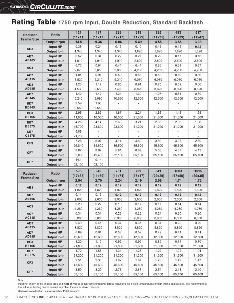
Rating Table 1750 rpm Input, Double Reduction, Standard Backlash
121 187 289 319 385 493 517(11x11) (11x17) (17x17) (11x29) (11x35) (17x29) (11x47)
Output rpm 14.5 9.36 6.06 5.49 4.55 3.55 3.38Input HP 0.36 0.24 0.15 0.19 0.16 0.12 0.12
Output lb-in 1,340 1,340 1,340 1,820 1,820 1,820 1,820Input HP 0.52 0.34 0.22 0.27 0.22 0.17 0.16
Output lb-in 1,910 1,910 1,910 2,600 2,600 2,600 2,600Input HP 0.72 0.64 0.41 0.44 0.36 0.28 0.27
Output lb-in 2,670 3,650 3,650 4,260 4,260 4,260 4,260Input HP 1.04 0.91 0.59 0.63 0.52 0.40 0.39
Output lb-in 3,820 5,210 5,210 6,080 6,080 6,080 6,080Input HP 1.23 1.17 0.85 0.91 0.75 0.59 0.56
Output lb-in 4,530 6,650 7,460 8,820 8,820 8,820 8,820Input HP 1.42 1.42 1.21 1.30 1.07 0.84 0.80
Output lb-in 5,240 8,090 10,660 12,600 12,600 12,600 12,600Input HP 2.59 1.68 - - - - -
Output lb-in 9,550 9,550 - - - - -Input HP 2.98 2.89 1.87 2.24 1.86 1.45 1.38
Output lb-in 11,000 16,500 16,500 21,800 21,800 21,800 21,800Input HP 4.25 4.14 2.68 3.21 2.66 2.08 1.98
Output lb-in 15,700 23,600 23,600 31,200 31,200 31,200 31,200Input HP 5.88 - - - - - -
Output lb-in 21,700 - - - - - -Input HP 7.28 6.07 4.14 4.69 3.89 3.03 2.89
Output lb-in 26,840 34,600 36,500 45,600 45,600 45,600 45,600Input HP 8.67 8.67 5.91 6.69 5.55 4.33 4.13
Output lb-in 32,000 49,400 52,100 65,100 65,100 65,100 65,100Input HP 14.1 9.14 - - - - -
Output lb-in 52,100 52,100 - - - - -
595 649 781 799 841 1003 1015(17x35) (11x59) (11x71) (17x47) (29x29) (17x59) (29x35)
Output rpm 2.94 2.70 2.24 2.19 2.08 1.74 1.72Input HP 0.12 0.12 0.12 0.12 0.12 0.12 0.12
Output lb-in 1,820 1,820 1,820 1,820 1,820 1,820 1,820Input HP 0.14 0.13 0.12 0.12 0.12 0.12 0.12
Output lb-in 2,600 2,600 2,600 2,600 2,600 2,600 2,600Input HP 0.23 0.22 0.18 0.17 0.17 0.14 0.14
Output lb-in 4,260 4,260 4,260 4,260 4,260 4,260 4,260Input HP 0.34 0.31 0.26 0.25 0.24 0.20 0.20
Output lb-in 6,080 6,080 6,080 6,080 6,080 6,080 6,080Input HP 0.49 0.45 0.37 0.36 0.34 0.29 0.29
Output lb-in 8,820 8,820 8,820 8,820 8,820 8,820 8,820Input HP 0.69 0.64 0.53 0.52 0.49 0.41 0.41
Output lb-in 12,600 12,600 12,600 12,600 12,600 12,600 12,600Input HP 1.20 1.10 0.92 0.90 0.85 0.71 0.70
Output lb-in 21,800 21,800 21,800 21,800 21,800 21,800 21,800Input HP 1.72 1.58 1.31 1.28 1.22 1.02 1.01
Output lb-in 31,200 31,200 31,200 31,200 31,200 31,200 31,200Input HP 2.51 2.30 1.92 1.87 1.78 1.49 1.47
Output lb-in 45,600 45,600 45,600 45,600 45,600 45,600 45,600Input HP 3.59 3.29 2.73 2.67 2.54 2.13 2.10
Output lb-in 65,100 65,100 65,100 65,100 65,100 65,100 65,100
Note:
Backlash specification is approximately1o (60 arc-min).
AC7AC115
Input HP shown in the shaded area and in bold type is to overcome breakway torque requirements in cold temperatures or high inertia applications. It is recommended that a torque limiting device is used to protect the unit or driven machine.
BE3BE165
Ratio
RatioReducerFrame Size
ReducerFrame Size
AB7AB105
AC7AC115
AD7AD145
BD7BD145
CE7CE375
BE3BE165
AB3
AB7AB105
AC3
AC3
AD3AD135
AD3AD135
BE7BE375
CF3
CF3
CF7
CF7
DF7
AD7AD145
BE7BE375
AB3
13SHIMPO DRIVES, INC. / 1701 GLENLAKE AVE ITASCA IL 60143 / P: 800.842.1479 / F: 630.924.7382 / WWW.SHIMPODRIVES.COM / [email protected]
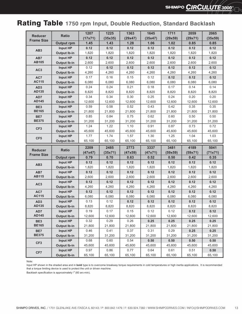
Rating Table 1750 rpm Input, Double Reduction, Standard Backlash
1207 1225 1363 1645 1711 2059 2065(17x71) (35x35) (29x47) (35x47) (29x59) (29x71) (35x59)
Output rpm 1.45 1.43 1.28 1.06 1.02 0.85 0.85Input HP 0.12 0.12 0.12 0.12 0.12 0.12 0.12
Output lb-in 1,820 1,820 1,820 1,820 1,820 1,820 1,820Input HP 0.12 0.12 0.12 0.12 0.12 0.12 0.12
Output lb-in 2,600 2,600 2,600 2,600 2,600 2,600 2,600Input HP 0.12 0.12 0.12 0.12 0.12 0.12 0.12
Output lb-in 4,260 4,260 4,260 4,260 4,260 4,260 4,260Input HP 0.17 0.16 0.15 0.12 0.12 0.12 0.12
Output lb-in 6,080 6,080 6,080 6,080 6,080 6,080 6,080Input HP 0.24 0.24 0.21 0.18 0.17 0.14 0.14
Output lb-in 8,820 8,820 8,820 8,820 8,820 8,820 8,820Input HP 0.34 0.34 0.30 0.25 0.24 0.20 0.20
Output lb-in 12,600 12,600 12,600 12,600 12,600 12,600 12,600Input HP 0.59 0.58 0.52 0.43 0.42 0.35 0.35
Output lb-in 21,800 21,800 21,800 21,800 21,800 21,800 21,800Input HP 0.85 0.84 0.75 0.62 0.60 0.50 0.50
Output lb-in 31,200 31,200 31,200 31,200 31,200 31,200 31,200Input HP 1.24 1.22 1.10 0.91 0.87 0.73 0.72
Output lb-in 45,600 45,600 45,600 45,600 45,600 45,600 45,600Input HP 1.77 1.74 1.57 1.30 1.25 1.04 1.03
Output lb-in 65,100 65,100 65,100 65,100 65,100 65,100 65,100
2209 2485 2773 3337 3481 4189 5041(47x47) (35x71) (47x59) (47x71) (59x59) (59x71) (71x71)
Output rpm 0.79 0.70 0.63 0.52 0.50 0.42 0.35Input HP 0.12 0.12 0.12 0.12 0.12 0.12 0.12
Output lb-in 1,820 1,820 1,820 1,820 1,820 1,820 1,820Input HP 0.12 0.12 0.12 0.12 0.12 0.12 0.12
Output lb-in 2,600 2,600 2,600 2,600 2,600 2,600 2,600Input HP 0.12 0.12 0.12 0.12 0.12 0.12 0.12
Output lb-in 4,260 4,260 4,260 4,260 4,260 4,260 4,260Input HP 0.12 0.12 0.12 0.12 0.12 0.12 0.12
Output lb-in 6,080 6,080 6,080 6,080 6,080 6,080 6,080Input HP 0.13 0.12 0.12 0.12 0.12 0.12 0.12
Output lb-in 8,820 8,820 8,820 8,820 8,820 8,820 8,820Input HP 0.19 0.17 0.15 0.12 0.12 0.12 0.12
Output lb-in 12,600 12,600 12,600 12,600 12,600 12,600 12,600Input HP 0.32 0.29 0.26 0.25 0.25 0.25 0.25
Output lb-in 21,800 21,800 21,800 21,800 21,800 21,800 21,800Input HP 0.46 0.41 0.37 0.31 0.29 0.25 0.25
Output lb-in 31,200 31,200 31,200 31,200 31,200 31,200 31,200Input HP 0.68 0.60 0.54 0.50 0.50 0.50 0.50
Output lb-in 45,600 45,600 45,600 45,600 45,600 45,600 45,600Input HP 0.97 0.86 0.77 0.64 0.61 0.51 0.50
Output lb-in 65,100 65,100 65,100 65,100 65,100 65,100 65,100
Note:
Backlash specification is approximately1o (60 arc-min).
Input HP shown in the shaded area and in bold type is to overcome breakway torque requirements in cold temperatures or high inertia applications. It is recommended that a torque limiting device is used to protect the unit or driven machine.
ReducerFrame Size
ReducerFrame Size
Ratio
AB7AB105
CF3
CF7
AC7AC115
AD7AD145
BE7BE375
AC3
AD3AD135
Ratio
AB7AB115
BE7BE375
CF5
AC7AC115
AD7AD145
AB3
AB3
AC3
AD3AD135
BE3BE165
BE3BE165
CF3

14 SHIMPO DRIVES, INC. / 1701 GLENLAKE AVE ITASCA IL 60143 / P: 800.842.1479 / F: 630.924.7382 / WWW.SHIMPODRIVES.COM / [email protected]
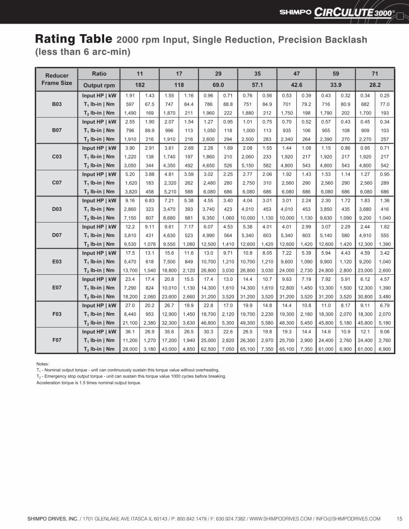
Rating Table 2000 rpm Input, Single Reduction, Standard Backlash
ReducerFrame Size
Ratio 11 17 29 35 47 59 71
Output rpm 182 118 69.0 57.1 42.6 33.9 28.2
A03Input HP | kW 0.92 0.68 0.82 0.61 0.51 0.38 0.47 0.35 0.33 0.25 0.25 0.18 0.17 0.12
T1 lb-in | Nm 285 32.3 390 44.5 420 47.4 460 52.2 440 49.7 410 46.8 330 37.5
T2 lb-in | Nm 521 58.8 724 81.7 769 86.8 847 95.6 802 90.5 764 86.3 608 68.6
A07Input HP | kW 1.22 0.91 1.09 0.81 0.68 0.51 0.62 0.46 0.44 0.33 0.33 0.25 0.22 0.16
T1 lb-in | Nm 381 43.0 530 59.4 560 63.2 620 69.5 590 66.3 550 62.4 440 50.1
T2 lb-in | Nm 521 58.8 724 81.7 769 86.8 847 95.6 802 90.5 764 86.3 608 68.6
B03Input HP | kW 2.17 1.62 1.53 1.14 1.08 0.81 0.86 0.64 0.61 0.46 0.48 0.36 0.39 0.29
T1 lb-in | Nm 676 76.4 736 83.2 890 101 856 96.7 813 91.9 805 90.9 779 88.0
T2 lb-in | Nm 1,690 191 1,840 208 2,230 251 2,140 242 2,030 230 2,010 227 1,950 220
B07Input HP | kW 3.40 2.54 2.40 1.79 1.70 1.27 1.35 1.00 0.96 0.71 0.75 0.56 0.60 0.45
T1 lb-in | Nm 1,060 120 1,160 131 1,400 158 1,340 151 1,280 144 1,250 141 1,220 137
T2 lb-in | Nm 1,910 216 1,910 216 2,600 294 2,600 294 2,600 294 2,600 294 2,600 294
C03Input HP | kW 5.02 3.75 3.87 2.89 2.41 1.80 2.22 1.65 1.53 1.14 1.22 0.91 1.02 0.76
T1 lb-in | Nm 1,570 177 1,870 211 1,990 224 2,200 249 2,050 231 2,050 231 2,050 231
T2 lb-in | Nm 3,930 442 4,680 527 4,980 561 5,500 621 5,130 578 5,130 578 5,130 578
C07Input HP | kW 7.38 5.51 6.43 4.79 4.02 3.00 3.69 2.75 2.56 1.91 2.04 1.52 1.69 1.26
T1 lb-in | Nm 2,300 260 3,100 350 3,300 373 3,660 414 3,420 386 3,420 386 3,410 385
T2 lb-in | Nm 3,820 431 5,210 588 6,080 686 6,080 686 6,080 686 6,080 686 6,080 686
D03Input HP | kW 10.4 7.78 9.84 7.34 6.21 4.64 5.50 4.10 4.10 3.06 3.15 2.35 2.50 1.86
T1 lb-in | Nm 3,250 367 4,740 536 5,110 577 5,460 617 5,460 617 5,260 595 5,020 568
T2 lb-in | Nm 8,130 919 9,550 1,080 12,600 1,420 12,600 1,420 12,600 1,420 12,600 1,420 12,600 1,420
D07Input HP | kW 16.3 12.16 13.62 10.2 8.60 6.41 7.62 5.69 5.68 4.23 4.35 3.24 3.46 2.58
T1 lb-in | Nm 5,080 574 6,570 742 7,070 799 7,570 855 7,570 855 7,280 822 6,960 786
T2 lb-in | Nm 9,550 1,080 9,550 1,080 12,600 1,420 12,600 1,420 12,600 1,420 12,600 1,420 12,600 1,420
E03Input HP | kW 24.0 17.9 18.8 14.0 13.9 10.4 11.6 8.65 7.71 5.75 6.34 4.73 4.93 3.68
T1 lb-in | Nm 7,490 846 9,100 1,024 11,400 1,290 11,500 1,300 10,300 1,160 10,600 1,200 9,900 1,120
T2 lb-in | Nm 15,700 1,770 22,800 2,560 28,500 3,230 28,800 3,250 25,800 2,900 26,500 3,000 24,800 2,800
E07Input HP | kW 31.3 23.3 27.7 20.7 23.1 17.2 19.1 14.2 12.80 9.55 10.5 7.83 8.16 6.09
T1 lb-in | Nm 9,760 1,103 13,400 1,510 19,000 2,150 19,000 2,140 17,100 1,930 17,600 1,990 16,400 1,860
T2 lb-in | Nm 15,700 1,770 23,600 2,660 31,200 3,520 31,200 3,520 31,200 3,520 31,200 3,520 31,200 3,520
F03Input HP | kW 38.8 28.9 36.0 26.9 30.8 23.0 26.9 20.1 19.5 14.6 14.8 11.06 12.3 9.18
T1 lb-in | Nm 12,100 1,366 17,400 1,960 25,300 2,860 26,700 3,020 26,000 2,940 24,800 2,800 24,800 2,800
T2 lb-in | Nm 30,300 3,420 43,500 4,900 63,300 7,150 65,100 7,350 65,000 7,340 62,000 7,000 62,000 7,000
F07Input HP | kW 51.0 38.0 47.4 35.4 40.5 30.2 35.4 26.4 25.7 19.2 19.5 14.5 16.2 12.1
T1 lb-in | Nm 15,900 1,800 22,900 2,580 33,300 3,760 35,100 3,970 34,300 3,870 32,600 3,690 32,600 3,690
T2 lb-in | Nm 39,800 4,500 52,100 5,880 65,100 7,350 65,100 7,350 65,100 7,350 65,100 7,350 65,100 7,350
Notes:T1 - Nominal output torque - unit can continuously sustain this torque value without overheating.T2 - Emergency stop output torque - unit can sustain this torque value 1000 cycles before breaking.Acceleration torque is 1.5 times nominal output torque.Backlash specification is approximately 1o (60 arc-min).
15SHIMPO DRIVES, INC. / 1701 GLENLAKE AVE ITASCA IL 60143 / P: 800.842.1479 / F: 630.924.7382 / WWW.SHIMPODRIVES.COM / [email protected]
Rating Table 2000 rpm Input, Single Reduction, Precision Backlash(less than 6 arc-min)
ReducerFrame Size
Ratio 11 17 29 35 47 59 71
Output rpm 182 118 69.0 57.1 42.6 33.9 28.2
B03Input HP | kW 1.91 1.43 1.55 1.16 0.96 0.71 0.76 0.56 0.53 0.39 0.43 0.32 0.34 0.25
T1 lb-in | Nm 597 67.5 747 84.4 786 88.8 751 84.9 701 79.2 716 80.9 682 77.0
T2 lb-in | Nm 1,490 169 1,870 211 1,960 222 1,880 212 1,750 198 1,790 202 1,700 193
B07Input HP | kW 2.55 1.90 2.07 1.54 1.27 0.95 1.01 0.75 0.70 0.52 0.57 0.43 0.45 0.34
T1 lb-in | Nm 796 89.9 996 113 1,050 118 1,000 113 935 106 955 108 909 103
T2 lb-in | Nm 1,910 216 1,910 216 2,600 294 2,500 283 2,340 264 2,390 270 2,270 257
C03Input HP | kW 3.90 2.91 3.61 2.69 2.26 1.69 2.08 1.55 1.44 1.08 1.15 0.86 0.95 0.71
T1 lb-in | Nm 1,220 138 1,740 197 1,860 210 2,060 233 1,920 217 1,920 217 1,920 217
T2 lb-in | Nm 3,050 344 4,350 492 4,650 526 5,150 582 4,800 543 4,800 543 4,800 542
C07Input HP | kW 5.20 3.88 4.81 3.59 3.02 2.25 2.77 2.06 1.92 1.43 1.53 1.14 1.27 0.95
T1 lb-in | Nm 1,620 183 2,320 262 2,480 280 2,750 310 2,560 290 2,560 290 2,560 289
T2 lb-in | Nm 3,820 458 5,210 588 6,080 686 6,080 686 6,080 686 6,080 686 6,080 686
D03Input HP | kW 9.16 6.83 7.21 5.38 4.55 3.40 4.04 3.01 3.01 2.24 2.30 1.72 1.83 1.36
T1 lb-in | Nm 2,860 323 3,470 393 3,740 423 4,010 453 4,010 453 3,850 435 3,680 416
T2 lb-in | Nm 7,150 807 8,680 981 9,350 1,060 10,000 1,130 10,000 1,130 9,630 1,090 9,200 1,040
D07Input HP | kW 12.2 9.11 9.61 7.17 6.07 4.53 5.38 4.01 4.01 2.99 3.07 2.29 2.44 1.82
T1 lb-in | Nm 3,810 431 4,630 523 4,990 564 5,340 603 5,340 603 5,140 580 4,910 555
T2 lb-in | Nm 9,530 1,076 9,550 1,080 12,500 1,410 12,600 1,420 12,600 1,420 12,600 1,420 12,300 1,390
E03Input HP | kW 17.5 13.1 15.6 11.6 13.0 9.71 10.8 8.05 7.22 5.39 5.94 4.43 4.59 3.42
T1 lb-in | Nm 5,470 618 7,500 849 10,700 1,210 10,700 1,210 9,600 1,090 9,900 1,120 9,200 1,040
T2 lb-in | Nm 13,700 1,540 18,800 2,120 26,800 3,030 26,800 3,030 24,000 2,730 24,800 2,800 23,000 2,600
E07Input HP | kW 23.4 17.4 20.8 15.5 17.4 13.0 14.4 10.7 9.63 7.19 7.92 5.91 6.12 4.57
T1 lb-in | Nm 7,290 824 10,010 1,130 14,300 1,610 14,300 1,610 12,800 1,450 13,300 1,500 12,300 1,390
T2 lb-in | Nm 18,200 2,060 23,600 2,660 31,200 3,520 31,200 3,520 31,200 3,520 31,200 3,520 30,800 3,480
F03Input HP | kW 27.0 20.2 26.7 19.9 22.8 17.0 19.9 14.8 14.4 10.8 11.0 8.17 9.11 6.79
T1 lb-in | Nm 8,440 953 12,900 1,450 18,700 2,120 19,700 2,230 19,300 2,180 18,300 2,070 18,300 2,070
T2 lb-in | Nm 21,100 2,380 32,300 3,630 46,800 5,300 49,300 5,580 48,300 5,450 45,800 5,180 45,800 5,180
F07Input HP | kW 36.1 26.9 35.6 26.5 30.3 22.6 26.5 19.8 19.3 14.4 14.6 10.9 12.1 9.06
T1 lb-in | Nm 11,200 1,270 17,200 1,940 25,000 2,820 26,300 2,970 25,700 2,900 24,400 2,760 24,400 2,760
T2 lb-in | Nm 28,000 3,180 43,000 4,850 62,500 7,050 65,100 7,350 65,100 7,350 61,000 6,900 61,000 6,900
Notes:T1 - Nominal output torque - unit can continuously sustain this torque value without overheating.T2 - Emergency stop output torque - unit can sustain this torque value 1000 cycles before breaking.Acceleration torque is 1.5 times nominal output torque.
16 SHIMPO DRIVES, INC. / 1701 GLENLAKE AVE ITASCA IL 60143 / P: 800.842.1479 / F: 630.924.7382 / WWW.SHIMPODRIVES.COM / [email protected]
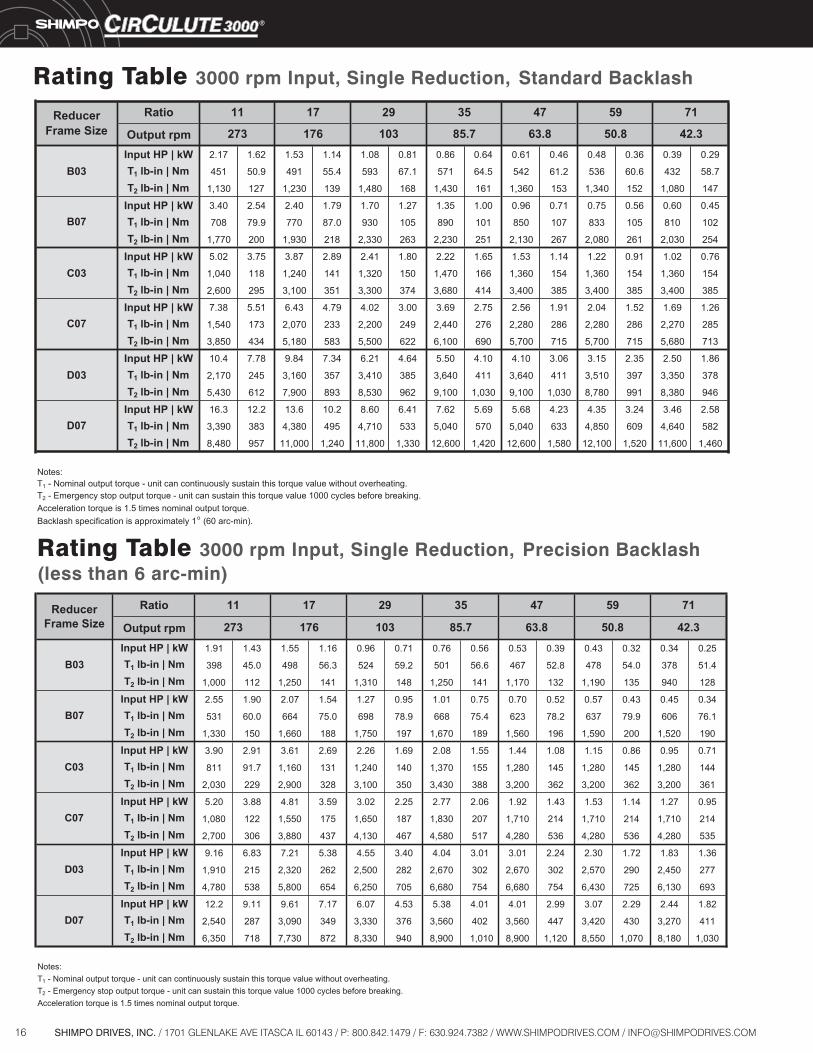
Rating Table 3000 rpm Input, Single Reduction, Standard Backlash
ReducerFrame Size
Ratio 11 17 29 35 47 59 71
Output rpm 273 176 103 85.7 63.8 50.8 42.3
B03Input HP | kW 2.17 1.62 1.53 1.14 1.08 0.81 0.86 0.64 0.61 0.46 0.48 0.36 0.39 0.29
T1 lb-in | Nm 451 50.9 491 55.4 593 67.1 571 64.5 542 61.2 536 60.6 432 58.7
T2 lb-in | Nm 1,130 127 1,230 139 1,480 168 1,430 161 1,360 153 1,340 152 1,080 147
B07Input HP | kW 3.40 2.54 2.40 1.79 1.70 1.27 1.35 1.00 0.96 0.71 0.75 0.56 0.60 0.45
T1 lb-in | Nm 708 79.9 770 87.0 930 105 890 101 850 107 833 105 810 102
T2 lb-in | Nm 1,770 200 1,930 218 2,330 263 2,230 251 2,130 267 2,080 261 2,030 254
C03Input HP | kW 5.02 3.75 3.87 2.89 2.41 1.80 2.22 1.65 1.53 1.14 1.22 0.91 1.02 0.76
T1 lb-in | Nm 1,040 118 1,240 141 1,320 150 1,470 166 1,360 154 1,360 154 1,360 154
T2 lb-in | Nm 2,600 295 3,100 351 3,300 374 3,680 414 3,400 385 3,400 385 3,400 385
C07Input HP | kW 7.38 5.51 6.43 4.79 4.02 3.00 3.69 2.75 2.56 1.91 2.04 1.52 1.69 1.26
T1 lb-in | Nm 1,540 173 2,070 233 2,200 249 2,440 276 2,280 286 2,280 286 2,270 285
T2 lb-in | Nm 3,850 434 5,180 583 5,500 622 6,100 690 5,700 715 5,700 715 5,680 713
D03Input HP | kW 10.4 7.78 9.84 7.34 6.21 4.64 5.50 4.10 4.10 3.06 3.15 2.35 2.50 1.86
T1 lb-in | Nm 2,170 245 3,160 357 3,410 385 3,640 411 3,640 411 3,510 397 3,350 378
T2 lb-in | Nm 5,430 612 7,900 893 8,530 962 9,100 1,030 9,100 1,030 8,780 991 8,380 946
D07Input HP | kW 16.3 12.2 13.6 10.2 8.60 6.41 7.62 5.69 5.68 4.23 4.35 3.24 3.46 2.58
T1 lb-in | Nm 3,390 383 4,380 495 4,710 533 5,040 570 5,040 633 4,850 609 4,640 582
T2 lb-in | Nm 8,480 957 11,000 1,240 11,800 1,330 12,600 1,420 12,600 1,580 12,100 1,520 11,600 1,460
Notes:T1 - Nominal output torque - unit can continuously sustain this torque value without overheating.T2 - Emergency stop output torque - unit can sustain this torque value 1000 cycles before breaking.Acceleration torque is 1.5 times nominal output torque.Backlash specification is approximately 1o (60 arc-min).
Ratio
Output rpmInput HP | kW 1.91 1.43 1.55 1.16 0.96 0.71 0.76 0.56 0.53 0.39 0.43 0.32 0.34 0.25
T1 lb-in | Nm 398 45.0 498 56.3 524 59.2 501 56.6 467 52.8 478 54.0 378 51.4
T2 lb-in | Nm 1,000 112 1,250 141 1,310 148 1,250 141 1,170 132 1,190 135 940 128
Input HP | kW 2.55 1.90 2.07 1.54 1.27 0.95 1.01 0.75 0.70 0.52 0.57 0.43 0.45 0.34
T1 lb-in | Nm 531 60.0 664 75.0 698 78.9 668 75.4 623 78.2 637 79.9 606 76.1
T2 lb-in | Nm 1,330 150 1,660 188 1,750 197 1,670 189 1,560 196 1,590 200 1,520 190
Input HP | kW 3.90 2.91 3.61 2.69 2.26 1.69 2.08 1.55 1.44 1.08 1.15 0.86 0.95 0.71
T1 lb-in | Nm 811 91.7 1,160 131 1,240 140 1,370 155 1,280 145 1,280 145 1,280 144
T2 lb-in | Nm 2,030 229 2,900 328 3,100 350 3,430 388 3,200 362 3,200 362 3,200 361
Input HP | kW 5.20 3.88 4.81 3.59 3.02 2.25 2.77 2.06 1.92 1.43 1.53 1.14 1.27 0.95
T1 lb-in | Nm 1,080 122 1,550 175 1,650 187 1,830 207 1,710 214 1,710 214 1,710 214
T2 lb-in | Nm 2,700 306 3,880 437 4,130 467 4,580 517 4,280 536 4,280 536 4,280 535
Input HP | kW 9.16 6.83 7.21 5.38 4.55 3.40 4.04 3.01 3.01 2.24 2.30 1.72 1.83 1.36
T1 lb-in | Nm 1,910 215 2,320 262 2,500 282 2,670 302 2,670 302 2,570 290 2,450 277
T2 lb-in | Nm 4,780 538 5,800 654 6,250 705 6,680 754 6,680 754 6,430 725 6,130 693
Input HP | kW 12.2 9.11 9.61 7.17 6.07 4.53 5.38 4.01 4.01 2.99 3.07 2.29 2.44 1.82
T1 lb-in | Nm 2,540 287 3,090 349 3,330 376 3,560 402 3,560 447 3,420 430 3,270 411
T2 lb-in | Nm 6,350 718 7,730 872 8,330 940 8,900 1,010 8,900 1,120 8,550 1,070 8,180 1,030
Notes:T1 - Nominal output torque - unit can continuously sustain this torque value without overheating.T2 - Emergency stop output torque - unit can sustain this torque value 1000 cycles before breaking.Acceleration torque is 1.5 times nominal output torque.
ReducerFrame Size
B07
B03
D07
C07
D03
C03
11 17 29 35 47 59 71
273 176 103 85.7 63.8 50.8 42.3
Rating Table 3000 rpm Input, Single Reduction, Precision Backlash(less than 6 arc-min)
17SHIMPO DRIVES, INC. / 1701 GLENLAKE AVE ITASCA IL 60143 / P: 800.842.1479 / F: 630.924.7382 / WWW.SHIMPODRIVES.COM / [email protected]
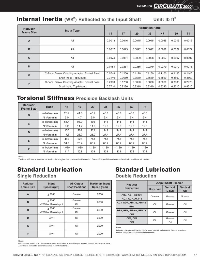
Internal Inertia (WK ) Reflected to the Input Shaft
ReducerFrame Size
InputSpeed (rpm)
All OutputShaft Positions
Maximum Input Speed (rpm)
A < 2000 Grease 2000
B< 2000 Grease
3600>2000 or Servo Input Oil
C< 2000 Grease
3600>2000 or Servo Input Oil
D Any Oil 3600
E Any Oil 2000
F Any Oil 2000
Notes:Oil lubrication for B01 - C07 for non-servo motor applications is available upon request. Consult Maintenance, Parts, & Instruction Manual for specific lubrication recommendations.
ReducerFrame Size
Output Shaft Position
Horizonal VerticalDown
VerticalUp
AB3, AB7, AB105Grease Grease Grease
AC3, AC7, AC115AD3, AD7, AD135, AD145
Oil Grease OilBD7
BE3, BE7, BE165, BE375Oil Grease Oil
CE7CF3, CF7
OilGrease
OilDF7 Oil
Notes:Lubrication type is based on 1750 RPM input. Consult Maintenance, Parts, & Instruction Manual for specific lubrication recommendations.
2
Torsional Stiffness Precision Backlash Units
Unit: lb ft2
Standard LubricationSingle Reduction
Standard LubricationDouble Reduction
11 17 29 35 47 59 71
A
B
C
D
C-Face, Servo, Coupling Adaptor, Shovel Base 0.0748 0.1250 0.1170 0.1160 0.1150 0.1150 0.1140Shaft Input, Top Mount 0.3140 0.3680 0.3560 0.3560 0.3560 0.3560 0.3560
C-Face, Servo, Coupling Adaptor, Shovel Base 0.2080 0.1780 0.3090 0.3030 0.3030 0.3030 0.2970Shaft Input, Top Mount 0.7710 0.7120 0.8310 0.8310 0.8310 0.8310 0.8310
Reduction Ratio
E
0.0184 0.0261 0.0285 0.0279 0.0279 0.0279 0.0273
0.0074
F
All
All
Input Type
All
All
ReducerFrame Size
0.0081 0.0099 0.0098 0.0097
0.0022
0.0015
0.0097 0.0097
0.0022 0.0022 0.0022
0.0015 0.0015 0.00150.0013 0.0016 0.0015
0.0017 0.0023 0.0022
ReducerFrame Size Ratio 11 17 29 35 47 59 71
Bin-lbs/arc-min 26.9 41.6 43.9 48.1 48.1 48.1 48.1Nm/arc-min 3.0 4.7 5.0 5.4 5.4 5.4 5.4
Cin-lbs/arc-min 54.4 98.9 105 111 111 111 111Nm/arc-min 6.2 11.2 11.9 12.6 12.6 12.6 12.6
Din-lbs/arc-min 157 203 223 242 242 242 242Nm/arc-min 17.8 23.0 25.2 27.4 27.4 27.4 27.4
Ein-lbs/arc-min 485 622 753 753 753 753 753Nm/arc-min 54.8 70.4 85.2 85.2 85.2 85.2 85.2
F in-lbs/arc-min 1,030 1,080 1,180 1,180 1,180 1,180 1,180Nm/arc-min 117 122 133 133 133 133 133
Notes:Torsional stiffness of standard backlash units is higher than precision backlash units. Contact Shimpo Drives Customer Service for additional information.
18 SHIMPO DRIVES, INC. / 1701 GLENLAKE AVE ITASCA IL 60143 / P: 800.842.1479 / F: 630.924.7382 / WWW.SHIMPODRIVES.COM / [email protected]
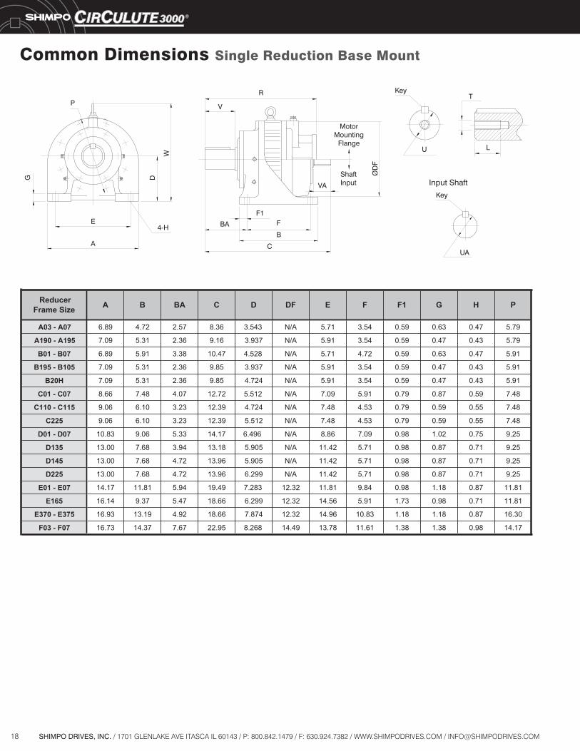
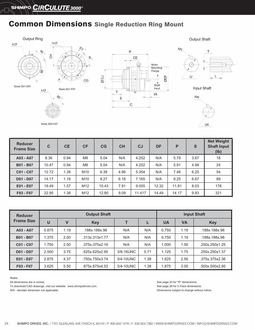
Common Dimensions Single Reduction Base Mount
A03 - A07 6.89 4.72 2.57 8.36 3.543 N/A 5.71 3.54 0.59 0.63 0.47 5.79
A190 - A195 7.09 5.31 2.36 9.16 3.937 N/A 5.91 3.54 0.59 0.47 0.43 5.79
B01 - B07 6.89 5.91 3.38 10.47 4.528 N/A 5.71 4.72 0.59 0.63 0.47 5.91
B195 - B105 7.09 5.31 2.36 9.85 3.937 N/A 5.91 3.54 0.59 0.47 0.43 5.91
B20H 7.09 5.31 2.36 9.85 4.724 N/A 5.91 3.54 0.59 0.47 0.43 5.91
C01 - C07 8.66 7.48 4.07 12.72 5.512 N/A 7.09 5.91 0.79 0.87 0.59 7.48
C110 - C115 9.06 6.10 3.23 12.39 4.724 N/A 7.48 4.53 0.79 0.59 0.55 7.48
C225 9.06 6.10 3.23 12.39 5.512 N/A 7.48 4.53 0.79 0.59 0.55 7.48
D01 - D07 10.83 9.06 5.33 14.17 6.496 N/A 8.86 7.09 0.98 1.02 0.75 9.25
D135 13.00 7.68 3.94 13.18 5.905 N/A 11.42 5.71 0.98 0.87 0.71 9.25
D145 13.00 7.68 4.72 13.96 5.905 N/A 11.42 5.71 0.98 0.87 0.71 9.25
D225 13.00 7.68 4.72 13.96 6.299 N/A 11.42 5.71 0.98 0.87 0.71 9.25
E01 - E07 14.17 11.81 5.94 19.49 7.283 12.32 11.81 9.84 0.98 1.18 0.87 11.81
E165 16.14 9.37 5.47 18.66 6.299 12.32 14.56 5.91 1.73 0.98 0.71 11.81
E370 - E375 16.93 13.19 4.92 18.66 7.874 12.32 14.96 10.83 1.18 1.18 0.87 16.30
F03 - F07 16.73 14.37 7.67 22.95 8.268 14.49 13.78 11.61 1.38 1.38 0.98 14.17
Reducer Frame Size A B BA C D DF E F F1 G H P
Input Shaft
R
V
BA4-HE
P
A
W
DG
F1F
VA
ØD
F
ShaftInput
Key
Key
UA
U
T
L
MotorMounting
Flange
B
C
19SHIMPO DRIVES, INC. / 1701 GLENLAKE AVE ITASCA IL 60143 / P: 800.842.1479 / F: 630.924.7382 / WWW.SHIMPODRIVES.COM / [email protected]
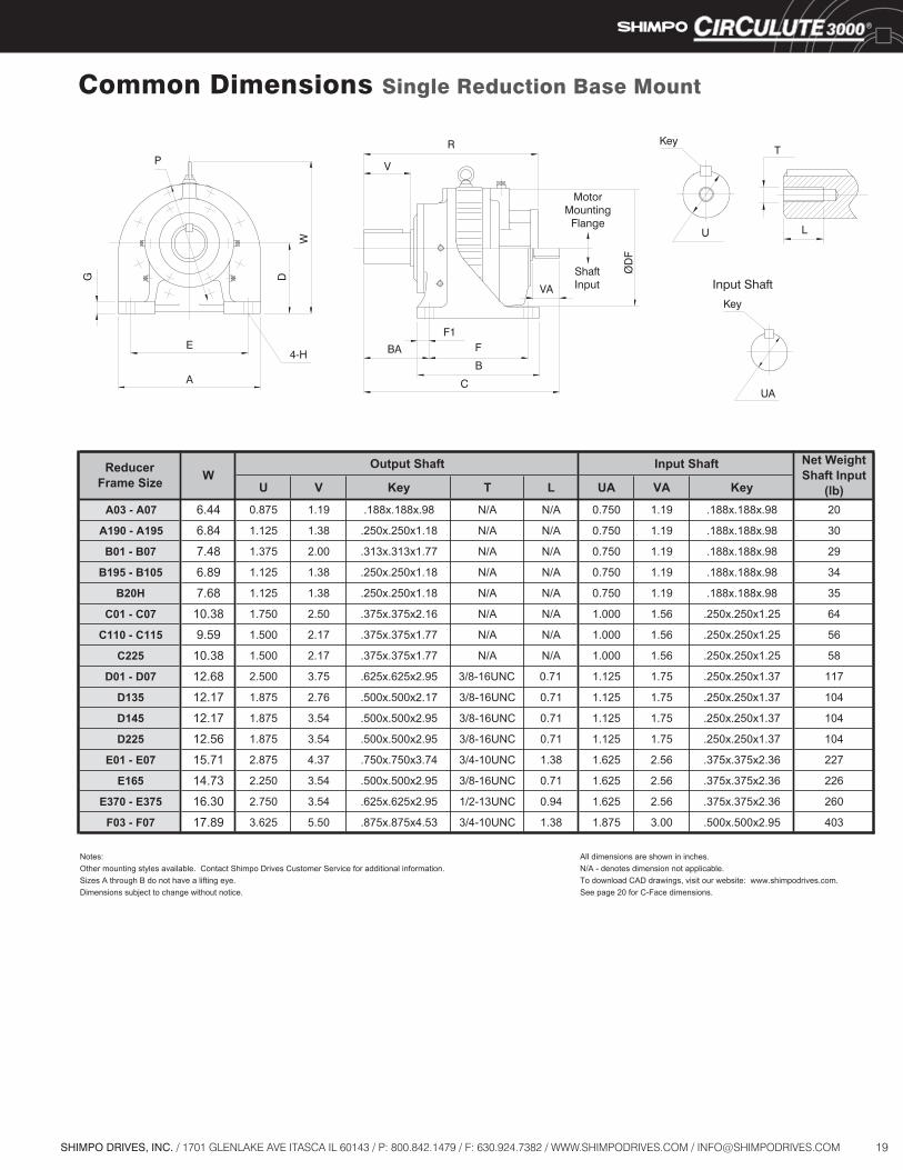
U V Key T L UA VA Key
A03 - A07 6.44 0.875 1.19 .188x.188x.98 N/A N/A 0.750 1.19 .188x.188x.98 20
A190 - A195 6.84 1.125 1.38 .250x.250x1.18 N/A N/A 0.750 1.19 .188x.188x.98 30
B01 - B07 7.48 1.375 2.00 .313x.313x1.77 N/A N/A 0.750 1.19 .188x.188x.98 29
B195 - B105 6.89 1.125 1.38 .250x.250x1.18 N/A N/A 0.750 1.19 .188x.188x.98 34
B20H 7.68 1.125 1.38 .250x.250x1.18 N/A N/A 0.750 1.19 .188x.188x.98 35
C01 - C07 10.38 1.750 2.50 .375x.375x2.16 N/A N/A 1.000 1.56 .250x.250x1.25 64
C110 - C115 9.59 1.500 2.17 .375x.375x1.77 N/A N/A 1.000 1.56 .250x.250x1.25 56
C225 10.38 1.500 2.17 .375x.375x1.77 N/A N/A 1.000 1.56 .250x.250x1.25 58
D01 - D07 12.68 2.500 3.75 .625x.625x2.95 3/8-16UNC 0.71 1.125 1.75 .250x.250x1.37 117
D135 12.17 1.875 2.76 .500x.500x2.17 3/8-16UNC 0.71 1.125 1.75 .250x.250x1.37 104
D145 12.17 1.875 3.54 .500x.500x2.95 3/8-16UNC 0.71 1.125 1.75 .250x.250x1.37 104
D225 12.56 1.875 3.54 .500x.500x2.95 3/8-16UNC 0.71 1.125 1.75 .250x.250x1.37 104
E01 - E07 15.71 2.875 4.37 .750x.750x3.74 3/4-10UNC 1.38 1.625 2.56 .375x.375x2.36 227
E165 14.73 2.250 3.54 .500x.500x2.95 3/8-16UNC 0.71 1.625 2.56 .375x.375x2.36 226
E370 - E375 16.30 2.750 3.54 .625x.625x2.95 1/2-13UNC 0.94 1.625 2.56 .375x.375x2.36 260
F03 - F07 17.89 3.625 5.50 .875x.875x4.53 3/4-10UNC 1.38 1.875 3.00 .500x.500x2.95 403
Notes: All dimensions are shown in inches.tonnoisnemidsetoned-A/N.noitamrofnilanoitiddarofecivreSremotsuCsevirDopmihStcatnoC.elbaliavaselytsgnitnuomrehtO applicable.
Sizes A through B do not have a lifting eye. To download CAD drawings, visit our website: www.shimpodrives.com.Dimensions subject to change without notice. See page 20 for C-Face dimensions.
Input Shaft Net Weight Shaft Input
(lb)
ReducerFrame Size W
Output Shaft
Input Shaft
R
V
BA4-HE
P
A
W
DG
F1F
VA
ØD
F
ShaftInput
Key
Key
UA
U
T
L
MotorMounting
Flange
B
C
Common Dimensions Single Reduction Base Mount

20 SHIMPO DRIVES, INC. / 1701 GLENLAKE AVE ITASCA IL 60143 / P: 800.842.1479 / F: 630.924.7382 / WWW.SHIMPODRIVES.COM / [email protected]
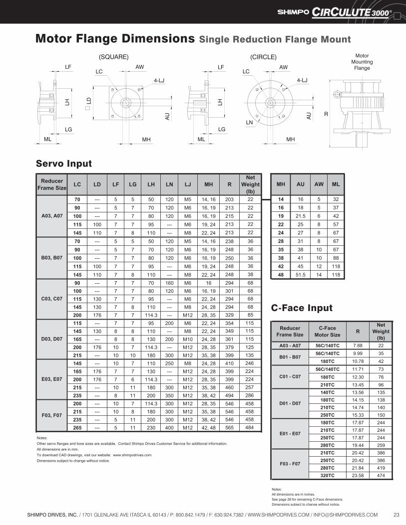
70 --- 5 5 50 120 M5 14, 16 203 22
90 --- 5 7 70 120 M6 16, 19 213 22
100 --- 7 7 80 120 M6 16, 19 215 22
115 100 7 7 95 --- M6 19, 24 213 22
145 110 7 8 110 --- M8 22, 24 213 28
70 --- 5 5 50 120 M5 14, 16 238 36
90 --- 5 7 70 120 M6 16, 19 248 36
100 --- 7 7 80 120 M6 16, 19 250 36
115 100 7 7 95 --- M6 19, 24 248 36
145 110 7 8 110 --- M8 22, 24 248 3890 --- 7 7 70 160 M6 16 294 68
100 --- 7 7 80 120 M6 16, 19 301 68115 130 7 7 95 --- M6 22, 24 294 68145 130 7 8 110 --- M8 24, 28 294 68200 176 7 7 114.3 --- M12 28, 35 329 85115 --- 7 7 95 200 M6 22, 24 354 115145 130 8 8 110 --- M8 22, 24 349 115165 --- 8 8 130 200 M10 24, 28 361 115200 176 10 7 114.3 --- M12 28, 35 379 125215 --- 10 10 180 300 M12 35, 38 399 135145 --- 10 7 110 250 M8 24, 28 410 246165 176 7 7 130 --- M12 24, 28 399 224200 176 7 6 114.3 --- M12 28, 35 399 224215 --- 10 11 180 300 M12 35, 38 460 257235 --- 8 11 200 350 M12 38, 42 494 286200 --- 10 7 114.3 300 M12 28, 35 546 458215 --- 10 8 180 300 M12 35, 38 546 458235 --- 5 11 200 300 M12 38, 42 546 458265 --- 5 11 230 400 M12 42, 48 565 484
Notes:Other servo flanges and bore sizes are available. Contact Shimpo Drives Customer Service for additional information.All dimensions are in mm.To download CAD drawings, visit our website: www.shimpodrives.com.Dimensions subject to change without notice.
LNLH
A03, A07
B03, B07
LF
F03, F07
E03, E07
D03, D07
MHReducerFrame Size LJLD LG
C03, C07
LCNet
Weight(lb)
R
Servo Input
14 16 5 32
16 18 5 37
19 21.5 6 42
22 25 8 57
24 27 8 67
28 31 8 67
35 38 10 67
38 41 10 88
42 45 12 118
48 51.5 14 118
MLAWAUMH
Motor Flange Dimensions Single Reduction Base Mount

21SHIMPO DRIVES, INC. / 1701 GLENLAKE AVE ITASCA IL 60143 / P: 800.842.1479 / F: 630.924.7382 / WWW.SHIMPODRIVES.COM / [email protected]
Motor Flange Dimensions Single Reduction Base Mount
C-FaceMotor Size
A03 - A07 56C/140TC 7.88 22A190 - A195 56C/140TC 8.69 32
56C/140TC 9.99 35180TC 10.78 42
B195 - B105 56C/140TC 9.37 3656C/140TC 9.37 36
180TC 10.16 4756C/140TC 11.71 73
180TC 12.30 76210TC 13.45 96
56C/140TC 11.38 68180TC 11.97 72210TC 13.15 92
56C/140TC 11.38 70180TC 11.97 74210TC 13.15 94140TC 13.56 135180TC 14.15 138210TC 14.74 140250TC 15.33 150140TC 12.57 105180TC 13.16 115210TC 13.75 125250TC 14.34 135180TC 13.94 115210TC 14.53 125250TC 15.12 135
180TC/210TC/250TC 17.87 255280TC 19.44 270
180TC/210TC/250TC 17.05 233280TC 18.62 255
180TC/210TC/250TC 17.05 278280TC 18.62 288
210TC/250TC 20.42 414280TC 21.84 447320TC 23.58 502
C225
C110 - C115
D135
F03 - F07
ReducerFrame Size
C01 - C07
D01 - D07
E01 - E07
D145/D225
E165
E370 - E375
R
B01 - B07
B20H
Net
(lbs)Weight
C-Face Input
22 SHIMPO DRIVES, INC. / 1701 GLENLAKE AVE ITASCA IL 60143 / P: 800.842.1479 / F: 630.924.7382 / WWW.SHIMPODRIVES.COM / [email protected]
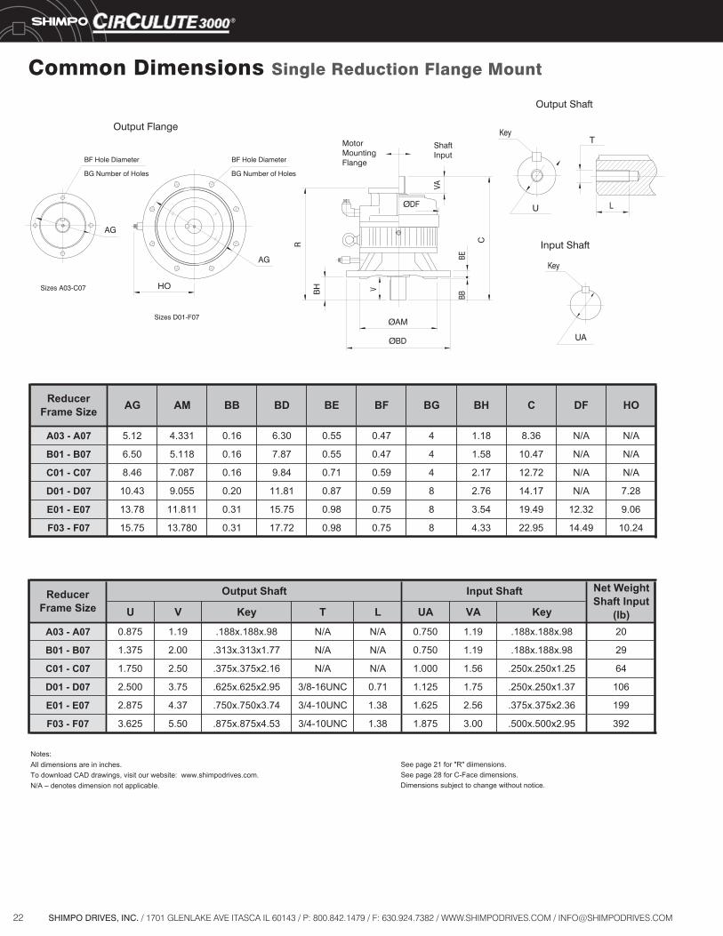
U V Key T L UA VA Key
A03 - A07 0.875 1.19 .188x.188x.98 N/A N/A 0.750 1.19 .188x.188x.98 20
B01 - B07 1.375 2.00 .313x.313x1.77 N/A N/A 0.750 1.19 .188x.188x.98 29
C01 - C07 1.750 2.50 .375x.375x2.16 N/A N/A 1.000 1.56 .250x.250x1.25 64
D01 - D07 2.500 3.75 .625x.625x2.95 3/8-16UNC 0.71 1.125 1.75 .250x.250x1.37 106
E01 - E07 2.875 4.37 .750x.750x3.74 3/4-10UNC 1.38 1.625 2.56 .375x.375x2.36 199
F03 - F07 3.625 5.50 .875x.875x4.53 3/4-10UNC 1.38 1.875 3.00 .500x.500x2.95 392
Notes:snemiid"R"rof12egapeeS ions.All dimensions are in inches.
See page 28 for C-Face dimensions..ecitontuohtiwegnahcottcejbussnoisnemiD
.moc.sevirdopmihs.www:etisbewruotisiv,sgniwardDACdaolnwodoTN/A – denotes dimension not applicable.
Net Weight Shaft Input
(lb)
Input ShaftReducerFrame Size
Output Shaft
Common Dimensions Single Reduction Flange Mount
HO
AG
C
BDØ
R
BBBE
AMØ
AG
L
T
U
UA
Key
Key
BH V
VA
DFØ
MotorMountingFlange
ShaftInput
Sizes D01-F07
Sizes A03-C07
BF Hole Diameter
BG Number of Holes
BF Hole Diameter
BG Number of Holes
Output Flange
Output Shaft
Input Shaft
A03 - A07 5.12 4.331 0.16 6.30 0.55 0.47 4 1.18 8.36 N/A N/A
B01 - B07 6.50 5.118 0.16 7.87 0.55 0.47 4 1.58 10.47 N/A N/A
C01 - C07 8.46 7.087 0.16 9.84 0.71 0.59 4 2.17 12.72 N/A N/A
D01 - D07 10.43 9.055 0.20 11.81 0.87 0.59 8 2.76 14.17 N/A 7.28
E01 - E07 13.78 11.811 0.31 15.75 0.98 0.75 8 3.54 19.49 12.32 9.06
F03 - F07 15.75 13.780 0.31 17.72 0.98 0.75 8 4.33 22.95 14.49 10.24
BG DF HOReducerFrame Size AG AM BB BD BE CBHBF
23SHIMPO DRIVES, INC. / 1701 GLENLAKE AVE ITASCA IL 60143 / P: 800.842.1479 / F: 630.924.7382 / WWW.SHIMPODRIVES.COM / [email protected]
Motor Flange Dimensions Single Reduction Flange Mount
70 --- 5 5 50 120 M5 14, 16 203 22
213 22
215 22213 22
213 22
248 36238 36
250 36248 36
248 38
329 85
361 115379 125399 135410 246399 224399 224460 257494 286
565 484546 458546 458546 458
349 115354 115
294 68294 68301 68294 68
90 --- 5 7 70 120 M6 16, 19
100 --- 7 7 80 120 M6 16, 19
115 100 7 7 95 --- M6 19, 24
145 110 7 8 110 --- M8 22, 24
70 --- 5 5 50 120 M5 14, 16
90 --- 5 7 70 120 M6 16, 19
100 --- 7 7 80 120 M6 16, 19
115 100 7 7 95 --- M6 19, 24
145 110 7 8 110 --- M8 22, 2490 --- 7 7 70 160 M6 16100 --- 7 7 80 120 M6 16, 19115 130 7 7 95 --- M6 22, 24145 130 7 8 110 --- M8 24, 28200 176 7 7 114.3 --- M12 28, 35115 --- 7 7 95 200 M6 22, 24145 130 8 8 110 --- M8 22, 24165 --- 8 8 130 200 M10 24, 28200 176 10 7 114.3 --- M12 28, 35215 --- 10 10 180 300 M12 35, 38145 --- 10 7 110 250 M8 24, 28165 176 7 7 130 --- M12 24, 28200 176 7 6 114.3 --- M12 28, 35215 --- 10 11 180 300 M12 35, 38235 --- 8 11 200 350 M12 38, 42200 --- 10 7 114.3 300 M12 28, 35215 --- 10 8 180 300 M12 35, 38235 --- 5 11 200 300 M12 38, 42265 --- 5 11 230 400 M12 42, 48
Notes:Other servo flanges and bore sizes are available. Contact Shimpo Drives Customer Service for additional information.All dimensions are in mm.To download CAD drawings, visit our website: www.shimpodrives.com.Dimensions subject to change without notice.
LD LGLFNet
Weight(lb)
LN
F03, F07
E03, E07
D03, D07
MHReducerFrame Size LJ
A03, A07
B03, B07
C03, C07
RCL LH
14 16 5 32
16 18 5 37
19 21.5 6 42
22 25 8 57
24 27 8 67
28 31 8 67
35 38 10 67
38 41 10 88
42 45 12 118
48 51.5 14 118
MH MLAWAU
C-FaceMotor Size
A03 - A07 56C/140TC 7.88 22
56C/140TC 9.99 35
180TC 10.78 42
56C/140TC 11.71 73
180TC 12.30 76210TC 13.45 96140TC 13.56 135180TC 14.15 138210TC 14.74 140250TC 15.33 150180TC 17.87 244210TC 17.87 244250TC 17.87 244280TC 19.44 259210TC 20.42 386250TC 20.42 386280TC 21.84 419320TC 23.58 474
Notes:All dimensions are in inches.See page 28 for remaining C-Face dimensions.Dimensions subject to change without notice.
F03 - F07
ReducerFrame Size R
NetWeight
(lb)
D01 - D07
C01 - C07
B01 - B07
E01 - E07
Servo Input
C-Face Input
(SQUARE)
4-LJLD
ML
LG
AW LC
LH
MH
LF
(CIRCLE)
4-LJ
AU
LC
MH
LN
LH
AWLF
ML
LG
R
AU
MotorMounting
Flange
24 SHIMPO DRIVES, INC. / 1701 GLENLAKE AVE ITASCA IL 60143 / P: 800.842.1479 / F: 630.924.7382 / WWW.SHIMPODRIVES.COM / [email protected]
Common Dimensions Single Reduction Ring Mount
U V Key T L UA VA Key
A03 - A07 0.875 1.19 .188x.188x.98 N/A N/A 0.750 1.19 .188x.188x.98
B01 - B07 1.375 2.00 .313x.313x1.77 N/A N/A 0.750 1.19 .188x.188x.98
C01 - C07 1.750 2.50 .375x.375x2.16 N/A N/A 1.000 1.56 .250x.250x1.25
D01 - D07 2.500 3.75 .625x.625x2.95 3/8-16UNC 0.71 1.125 1.75 .250x.250x1.37
E01 - E07 2.875 4.37 .750x.750x3.74 3/4-10UNC 1.38 1.625 2.56 .375x.375x2.36
F03 - F07 3.625 5.50 .875x.875x4.53 3/4-10UNC 1.38 1.875 3.00 .500x.500x2.95
Notes:snemiid"R"rof32egapeeS ions.All dimensions are in inches.
See page 28 for C-Face dimensions..ecitontuohtiwegnahcottcejbussnoisnemiD
.moc.sevirdopmihs.www:etisbewruotisiv,sgniwardDACdaolnwodoTN/A - denotes dimension not applicable.
Input ShaftReducerFrame Size
Output Shaft
6-CF 14-CF
CH
VA
CC
JØ
CE
V
S
R
L
T
U
UA
Key
Key
DF
MotorMountingFlange
ShaftInput
Sizes A03-C07
Sizes D01-D07Sizes E01-F074-CF
60
CG
45
22.5
P
90°
°
°
°45°
Ø
Output ShaftOutput Ring
Input Shaft
A03 - A07 8.36 0.94 M8 5.04 N/A 4.252 N/A 5.79 3.67 18
B01 - B07 10.47 0.94 M8 5.04 N/A 4.252 N/A 5.91 4.99 24
C01 - C07 12.72 1.38 M10 6.38 4.96 5.354 N/A 7.48 6.20 54
D01 - D07 14.17 1.18 M10 8.27 6.18 7.165 N/A 9.25 6.67 89
E01 - E07 19.49 1.57 M12 10.43 7.91 9.055 12.32 11.81 8.03 178
F03 - F07 22.95 1.38 M12 12.80 9.09 11.417 14.49 14.17 9.83 321
CH DFCJCReducerFrame Size CE CF CG P S
Net Weight Shaft Input
(lb)

25SHIMPO DRIVES, INC. / 1701 GLENLAKE AVE ITASCA IL 60143 / P: 800.842.1479 / F: 630.924.7382 / WWW.SHIMPODRIVES.COM / [email protected]
Motor Flange Dimensions Single Reduction Ring Mount
70 --- 5 5 50 120 M5 14, 16 203 20
20
2020
26
31
3131
31
335858585875
9090
90
100110
294301294
294329
354349361379
399197175175208237
376376376402
410399399460
494546546546
565
90 --- 5 7 70 120 M6 16, 19 213
100 --- 7 7 80 120 M6 16, 19 215
115 100 7 7 95 --- M6 19, 24 213
145 110 7 8 110 --- M8 22, 24 213
70 --- 5 5 50 120 M5 14, 16 238
90 --- 5 7 70 120 M6 16, 19 248
100 --- 7 7 80 120 M6 16, 19 250
115 100 7 7 95 --- M6 19, 24 248
145 110 7 8 110 --- M8 22, 24 24890 --- 7 7 70 160 M6 16100 --- 7 7 80 120 M6 16, 19115 130 7 7 95 --- M6 22, 24145 130 7 8 110 --- M8 24, 28200 176 7 7 114.3 --- M12 28, 35115 --- 7 7 95 200 M6 22, 24145 130 8 8 110 --- M8 22, 24165 --- 8 8 130 200 M10 24, 28200 176 10 7 114.3 --- M12 28, 35215 --- 10 10 180 300 M12 35, 38145 --- 10 7 110 250 M8 24, 28165 176 7 7 130 --- M12 24, 28200 176 7 6 114.3 --- M12 28, 35215 --- 10 11 180 300 M12 35, 38235 --- 8 11 200 350 M12 38, 42200 --- 10 7 114.3 300 M12 28, 35215 --- 10 8 180 300 M12 35, 38235 --- 5 11 200 300 M12 38, 42265 --- 5 11 230 400 M12 42, 48
Notes:Other servo flanges and bore sizes are available. Contact Shimpo Drives Customer Service for additional information.All dimensions are in mm.To download CAD drawings, visit our website: www.shimpodrives.com.Dimensions subject to change without notice.
LC
A03, A07
RDL LH HMFL LJLNNet
Weight(lb)
F03, F07
E03, E07
D03, D07
LG
B03, B07
C03, C07
ReducerFrame Size
14 16 5 32
16 18 5 37
19 21.5 6 42
22 25 8 57
24 27 8 67
28 31 8 67
35 38 10 67
38 41 10 88
42 45 12 118
48 51.5 14 118
AWAU MLMH
Servo Input
C-Face Input
C-FaceMotor Size
A03 - A07 56C/140TC 7.88 20
56C/140TC 9.99 29
180TC 10.78 36
56C/140TC 11.71 64
180TC 12.30 67210TC 13.45 87140TC 13.56 107180TC 14.15 110210TC 14.74 112250TC 15.33 122180TC 17.87 206210TC 17.87 206250TC 17.87 206280TC 19.44 221210TC 20.42 332250TC 20.42 332280TC 21.84 365320TC 23.58 420
Notes:All dimensions are in inches.See page 28 for C-Face dimensions.
F03 - F07
ReducerFrame Size R
NetWeight
(lb)
D01 - D07
C01 - C07
B01 - B07
E01 - E07
4-LJ
(SQUARE)
LD
ML
LG
AW LC
LH
MH
AU
LF(CIRCLE)
4-LJ
AU
LC
MH
LN
LH
AWLF
ML
LG
MotorMountingFlange
R
26 SHIMPO DRIVES, INC. / 1701 GLENLAKE AVE ITASCA IL 60143 / P: 800.842.1479 / F: 630.924.7382 / WWW.SHIMPODRIVES.COM / [email protected]
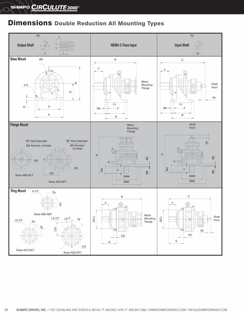
Dimensions Double Reduction All Mounting Types

27SHIMPO DRIVES, INC. / 1701 GLENLAKE AVE ITASCA IL 60143 / P: 800.842.1479 / F: 630.924.7382 / WWW.SHIMPODRIVES.COM / [email protected]
Dimensions Double Reduction All Mounting TypesC-FaceMotor
AB3, AB7 56C 6.89 6.50 5.118 5.91 3.38 0.16 7.87 0.55 0.47 2.00 4 13.15 0.94
AB105 56C 7.09 6.50 5.118 5.31 3.54 0.16 7.87 0.55 0.47 1.38 4 12.51 0.94
AC3, AC7 56C 8.66 8.46 7.087 7.48 4.07 0.16 9.84 0.71 0.59 2.50 4 15.08 1.38
AC115 56C 9.06 8.46 7.087 6.10 4.53 0.16 9.84 0.71 0.59 2.17 4 14.71 1.38
AD3, AD7 56C 10.83 10.43 9.055 9.06 5.33 0.20 11.81 0.87 0.59 3.75 8 16.73 1.18
AD135 56C 13.00 10.43 9.055 7.68 3.94 0.20 11.81 0.87 0.59 2.76 8 15.70 1.18
AD145 56C 13.00 10.43 9.055 7.68 4.72 0.20 11.81 0.87 0.59 3.54 8 16.48 1.18
BD7 56C/140TC 10.83 10.43 9.055 9.06 5.33 0.20 11.81 0.87 0.59 3.75 8 17.40 1.18
BE3, BE7 56C/140TC 14.17 13.78 11.811 11.81 5.94 0.31 15.75 0.98 0.75 4.37 8 20.08 1.57
BE165 56C/140TC 16.14 13.78 11.811 9.37 5.47 0.31 15.75 0.98 0.75 3.54 8 19.25 1.57
BE375 56C/140TC 16.93 13.78 11.811 13.19 4.92 0.31 15.75 0.98 0.75 3.54 8 19.25 1.57
CE7 180TC 14.17 13.78 11.811 11.81 5.94 0.31 15.75 0.98 0.75 4.37 8 21.30 1.57
CE375 180TC 16.93 13.78 11.811 13.19 4.92 0.31 15.75 0.98 0.75 3.54 8 19.25 1.57
56C/140TC
180TC
DF7 210TC 16.73 15.75 13.780 14.37 7.67 0.31 17.72 0.98 0.75 5.50 8 25.39 1.38
8 23.50CF3, CF7 14.37 7.6715.75 13.780
Frame CBBBMAGAA
16.73
BD BH BG ECFBEB
83.113.0 17.72 0.98 0.75 5.50
BAReducer
Size
C-FaceMotor
AB3, AB7 56C M8 5.04 4.24 4.252 4.527 5.71 4.72 0.59 0.63 0.47 N/A 5.91 12.67
AB105 56C M8 5.04 4.24 4.252 3.937 5.91 3.54 0.59 0.47 0.43 N/A 5.91 12.03
AC3, AC7 56C M10 6.38 4.96 5.354 5.512 7.09 5.91 0.79 0.87 0.59 N/A 7.48 14.59
AC115 56C M10 6.38 4.96 5.354 4.724 7.48 4.53 0.79 0.59 0.55 N/A 7.48 14.23
AD3, AD7 56C M10 8.27 6.18 7.165 6.496 8.86 7.09 0.98 1.02 0.75 7.28 9.25 16.23
AD135 56C M10 8.27 6.18 7.165 5.905 11.42 5.71 0.98 0.87 0.71 7.28 9.25 15.22
AD145 56C M10 8.27 6.18 7.165 5.905 11.42 5.71 0.98 0.87 0.71 7.28 9.25 16.00
BD7 56C/140TC M10 8.27 6.18 7.165 6.496 8.86 7.09 0.98 1.02 0.75 7.28 9.25 16.90
BE3, BE7 56C/140TC M12 10.43 7.91 9.055 7.283 11.81 9.84 0.98 1.18 0.87 9.06 11.81 19.57
BE165 56C/140TC M12 10.43 7.91 9.055 6.299 14.56 5.91 1.73 0.98 0.71 9.06 11.81 18.24
BE375 56C/140TC M12 10.43 7.91 9.055 7.874 14.96 10.83 1.18 1.18 0.87 9.06 11.81 18.24
CE7 180TC M12 10.43 7.91 9.055 7.283 11.81 9.84 0.98 1.18 0.87 9.06 11.81 20.91
CE375 180TC M12 10.43 7.91 9.055 7.874 14.96 10.83 1.18 1.18 0.87 9.06 11.81 20.12
56C/140TC 22.55
180TC 23.14
DF7 210TC M12 12.80 9.09 11.417 8.268 13.78 11.61 1.38 1.38 0.98 10.24 14.17 25.97
11.417 89.0862.890.9 1.38 1.38 71.4116.1187.31
Frame
CF3, CF7
CJCF CHCG
M12 12.80
HO
10.24
H P RD E F GF1Reducer
Size
C-FaceMotor U V Key T L UA VA Key w/C-Face w/o C-Face
AB3, AB7 56C 4.99 7.48 1.375 2.00 .313x.313x1.77 N/A N/A 0.750 1.19 .188x.188x.98 53 46
AB105 56C 4.37 6.89 1.125 1.38 .250x.250x1.18 N/A N/A 0.750 1.19 .188x.188x.98 54 52
AC3, AC7 56C 6.20 10.38 1.750 2.50 .375x.375x2.16 N/A N/A 0.750 1.19 .188x.188x.98 91 84
AC115 56C 5.87 8.46 1.500 2.17 .375x.375x1.77 N/A N/A 0.750 1.19 .188x.188x.98 96 85
AD3, AD7 56C 6.67 12.68 2.500 3.75 .625x.625x2.95 N/A N/A 0.750 1.19 .188x.188x.98 150 145
AD135 56C 6.46 12.17 1.875 2.76 .500x.500x2.17 3/8-16UNC 0.71 0.750 1.19 .188x.188x.98 143 141
AD145 56C 7.24 12.17 1.875 3.54 .500x.500x2.95 3/8-16UNC 0.71 0.750 1.19 .188x.188x.98 143 141
BD7 56C/140TC 6.67 12.68 2.500 3.75 .625x.625x2.95 N/A N/A 0.750 1.19 .188x.188x.98 161 150
BE3, BE7 56C/140TC 8.03 15.71 2.875 4.37 .750x.750x3.74 3/4-10UNC 1.38 0.750 1.19 .188x.188x.98 274 271
BE165 56C/140TC 7.20 14.73 2.250 3.54 .500x.500x2.95 3/8-16UNC 0.71 0.750 1.19 .188x.188x.98 271 269
BE375 56C/140TC 7.20 16.30 2.750 3.54 .625x.625x2.95 1/2-13UNC 0.94 0.750 1.19 .188x.188x.98 305 303
CE7 180TC 8.03 15.71 2.875 4.37 .750x.750x3.74 3/4-10UNC 1.38 1.000 1.56 .250x.250x1.25 304 293
CE375 180TC 7.20 16.30 2.750 3.54 .625x.625x2.95 1/2-13UNC 0.94 1.000 1.56 .250x.250x1.25 331 325
56C/140TC 481
180TC 489
DF7 210TC 9.09 17.89 3.625 5.50 .875x.875x4.53 3/4-10UNC 1.38 1.125 1.75 .250x.250x1.37 528 520
Notes:All dimensions are in inches. N/A - denotes dimension not applicable.To download CAD drawings, visit our website: www.shimp eeS.moc.sevirdo page 26 for C-Face dimensions.Size AB3 & AB7 do not include a lifting eye. Dimensions subject to change without notice.
08465.1
Input ShaftOutput Shaft
1.38 1.000 .250x.250x1.253.625 5.50CF3, CF7
Net Weight (lbs.)
9.09
S
.875x.875x4.53 3/4-10UNC
W
17.89
FrameReducer
Size
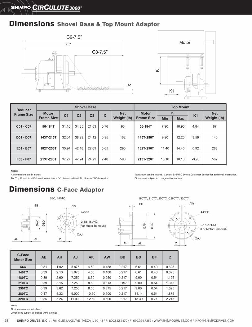
28 SHIMPO DRIVES, INC. / 1701 GLENLAKE AVE ITASCA IL 60143 / P: 800.842.1479 / F: 630.924.7382 / WWW.SHIMPODRIVES.COM / [email protected]
Min Max
Notes:All dimensions are in inches. Top Mount can be rotated. Contact SHIMPO Drives Customer Service for additional information.For Top Mount, total V-drive drive centers = "K" dimension listed PLUS motor "D" dimension. Dimensions subject to change without notice.
D01 - D07
C01 - C07
E01 - E07
F03 - F07 -0.98 562
140
288
213T-286T 213T-326T 15.10 18.1059037.27 47.24 24.29 2.40
11.40 14.40 0.92
9.20 12.20 3.59
182T-256T35.94 42.18 22.69 0.65 290
32.04 38.29
182T-256T
56-184T
143T-215T 24.12 0.95 162 145T-256T
0.76
MotorFrame Size
NetWeight (lb)
7.90 10.90 4.84 87
K
9356-184T 31.10 34.35 21.63
Top MountReducer
Frame Size K1
Shovel BaseMotor
Frame Size C1 C2 NetWeight (lb)C3 X
Dimensions Shovel Base & Top Mount Adaptor
Dimensions C-Face Adaptor
C-FaceMotor Size
56C 0.31 1.92 5.875 4.50 0.188 0.217 6.61 0.40 0.625140TC 0.39 2.13 5.875 4.50 0.188 0.217 6.61 0.40 0.875180TC 0.39 2.60 7.250 8.50 0.250 0.217 9.00 0.54 1.125210TC 0.39 3.15 7.250 8.50 0.313 0.197 9.00 0.54 1.375250TC 0.39 3.62 7.250 8.50 0.375 0.217 9.00 0.54 1.625280TC 0.47 4.33 9.000 10.50 0.500 0.217 11.14 0.54 1.875320TC 0.35 5.24 11.000 12.50 0.500 0.217 13.39 0.71 2.215
All dimensions are in inches.Notes:
Dimensions subject to change without notice.
ZAW BB BD BFAE AH AJ AK
2-3/8-16UNC(For Motor Removal)
(For Motor Removal)
BB AW
BD
Ø
180TC, 210TC, 250TC, C280TC, 320TC56C, 140TC
4-ØBF
BD
Ø
BB AW
AK
Ø AK
Ø
AJØ
ZAH AEAH AE Z
AJØ
4-ØBF
2-1/2-13UNC
C2-7.5”
C1
X
C3-7.5”
Motor
K1
K
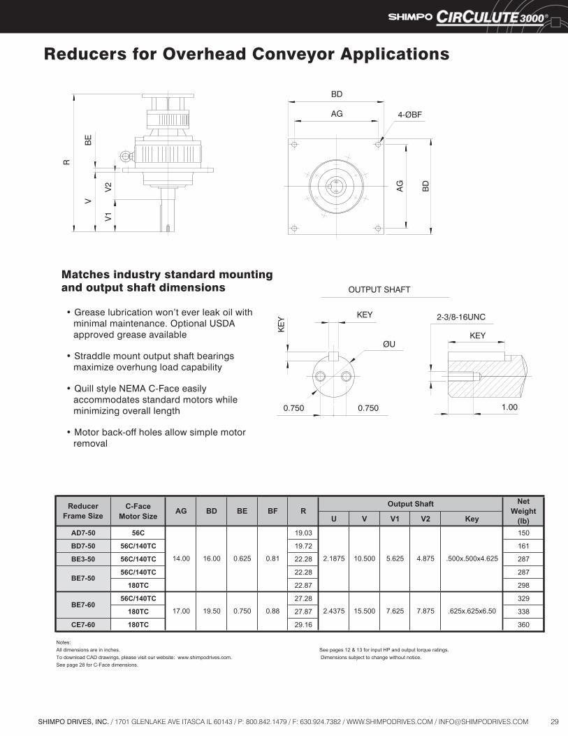
29SHIMPO DRIVES, INC. / 1701 GLENLAKE AVE ITASCA IL 60143 / P: 800.842.1479 / F: 630.924.7382 / WWW.SHIMPODRIVES.COM / [email protected]
C-FaceMotor Size U V V1 V2 Key
AD7-50 56C 05130.91
BD7-50 56C/140TC 16127.91
BE3-50 56C/140TC 78282.22
56C/140TC 78282.22
180TC 89278.22
56C/140TC 92382.72
180TC 83378.72
CE7-60 180TC 06361.92
Notes:All dimensions are in inches. See pages 12 & 13 for input HP and output torque ratings.To download CAD drawings, please visit our website: www.shimpodrives.com. Dimensions subject to change without notice.See page 28 for C-Face dimensions.
ReducerFrame Size
BE7-600.750 0.88
0.81
BE7-50
Output Shaft NetWeight
(lb)AG BD BE BF R
2.1875
2.437517.00 19.50
14.00 16.00 0.625
.625x.625x6.50
10.500 5.625 4.875 .500x.500x4.625
15.500 7.625 7.875
Reducers for Overhead Conveyor Applications
OUTPUT SHAFT
2-3/8-16UNC
KEY
KEY
0.7500.750
KE
Y
1.00
ØU
• Grease lubrication won’t ever leak oil with minimal maintenance. Optional USDA approved grease available
• Straddle mount output shaft bearings maximize overhung load capability
• Quill style NEMA C-Face easily accommodates standard motors while minimizing overall length
• Motor back-off holes allow simple motor removal
BD
R
BE
V
V1
V2
4-ØBF
BD
AG
AG
Matches industry standard mounting and output shaft dimensions
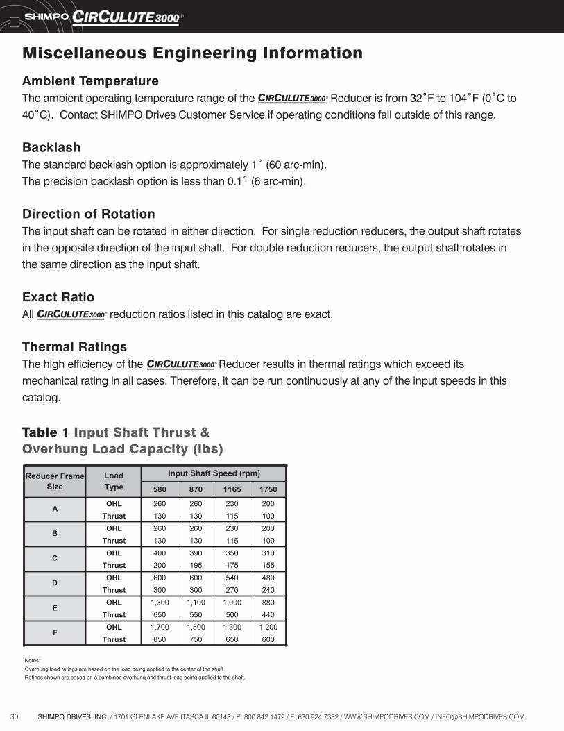
30 SHIMPO DRIVES, INC. / 1701 GLENLAKE AVE ITASCA IL 60143 / P: 800.842.1479 / F: 630.924.7382 / WWW.SHIMPODRIVES.COM / [email protected]
Miscellaneous Engineering Information
Ambient TemperatureThe ambient operating temperature range of the Reducer is from 32˚F to 104˚F (0˚C to
40˚C). Contact SHIMPO Drives Customer Service if operating conditions fall outside of this range.
BacklashThe standard backlash option is approximately 1˚ (60 arc-min).
The precision backlash option is less than 0.1˚ (6 arc-min).
Direction of RotationThe input shaft can be rotated in either direction. For single reduction reducers, the output shaft rotates
in the opposite direction of the input shaft. For double reduction reducers, the output shaft rotates in
the same direction as the input shaft.
Exact RatioAll reduction ratios listed in this catalog are exact.
Thermal RatingsThe high efficiency of the Reducer results in thermal ratings which exceed its
mechanical rating in all cases. Therefore, it can be run continuously at any of the input speeds in this
catalog.
Table 1 Input Shaft Thrust &Overhung Load Capacity (lbs)
LoadType 580 870 1165 1750
A OHL 260 260 230 200Thrust 130 130 115 100
B OHL 260 260 230 200Thrust 130 130 115 100
C OHL 400 390 350 310Thrust 200 195 175 155
D OHL 600 600 540 480Thrust 300 300 270 240OHL 1,300 1,100 1,000 880
Thrust 650 550 500 440OHL 1,700 1,500 1,300 1,200
Thrust 850 750 650 600
Notes:Overhung load ratings are based on the load being applied to the center of the shaft.Ratings shown are based on a combined overhung and thrust load being applied to the shaft.
F
Input Shaft Speed (rpm)Reducer Frame Size
E
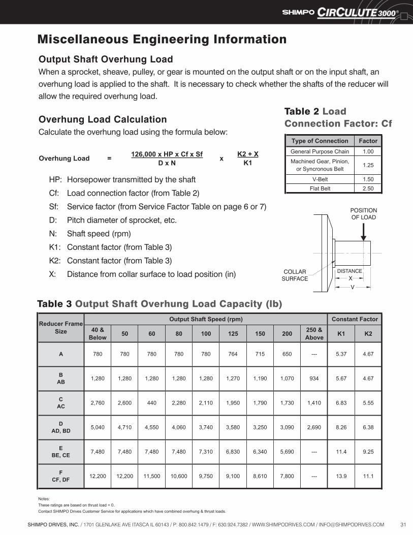
31SHIMPO DRIVES, INC. / 1701 GLENLAKE AVE ITASCA IL 60143 / P: 800.842.1479 / F: 630.924.7382 / WWW.SHIMPODRIVES.COM / [email protected]
Miscellaneous Engineering Information
Output Shaft Overhung LoadWhen a sprocket, sheave, pulley, or gear is mounted on the output shaft or on the input shaft, an
overhung load is applied to the shaft. It is necessary to check whether the shafts of the reducer will
allow the required overhung load.
Overhung Load CalculationCalculate the overhung load using the formula below:
Type of Connection FactorGeneral Purpose Chain 1.00
Machined Gear, Pinion,or Syncronous Belt
V-Belt 1.50Flat Belt 2.50
1.25
Table 2 LoadConnection Factor: Cf
Table 3 Output Shaft Overhung Load Capacity (lb)
K2 + XK1xOverhung Load = 126,000 x HP x Cf x Sf
D x N
POSITIONOF LOAD
COLLARSURFACE
DISTANCE
V
X
HP: Horsepower transmitted by the shaft
Cf: Load connection factor (from Table 2)
Sf: Service factor (from Service Factor Table on page 6 or 7)
D: Pitch diameter of sprocket, etc.
N: Shaft speed (rpm)
K1: Constant factor (from Table 3)
K2: Constant factor (from Table 3)
X: Distance from collar surface to load position (in)
40 & Below 50 60 80 100 125 150 200 250 &
Above K1 K2
Notes:These ratings are based on thrust load = 0.Contact SHIMPO Drives Customer Service for applications which have combined overhung & thrust loads.
FCF, DF
BAB
CAC
DAD, BD
EBE, CE
11.1---
5.67 4.67
6.83 5.55
8.26 6.38
11.4 9.25
13.9
934
1,410
2,690
---
7,800
1,280
2,600
4,710
7,480
12,200 11,500 10,600 9,750
3,090
5,690
4,550
1,1901,270
4,060
7,480 7,480 7,310 6,830
9,100
3,250
8,610
1,280
3,740 3,580
6,340
764 715
1,070
440 2,280 2,110 1,950 1,790 1,730
1,280
780 780 780
1,2801,280
2,760
5,040
7,480
12,200
Constant Factor
650A
Reducer Frame Size
780
Output Shaft Speed (rpm)
--- 5.37 4.67780
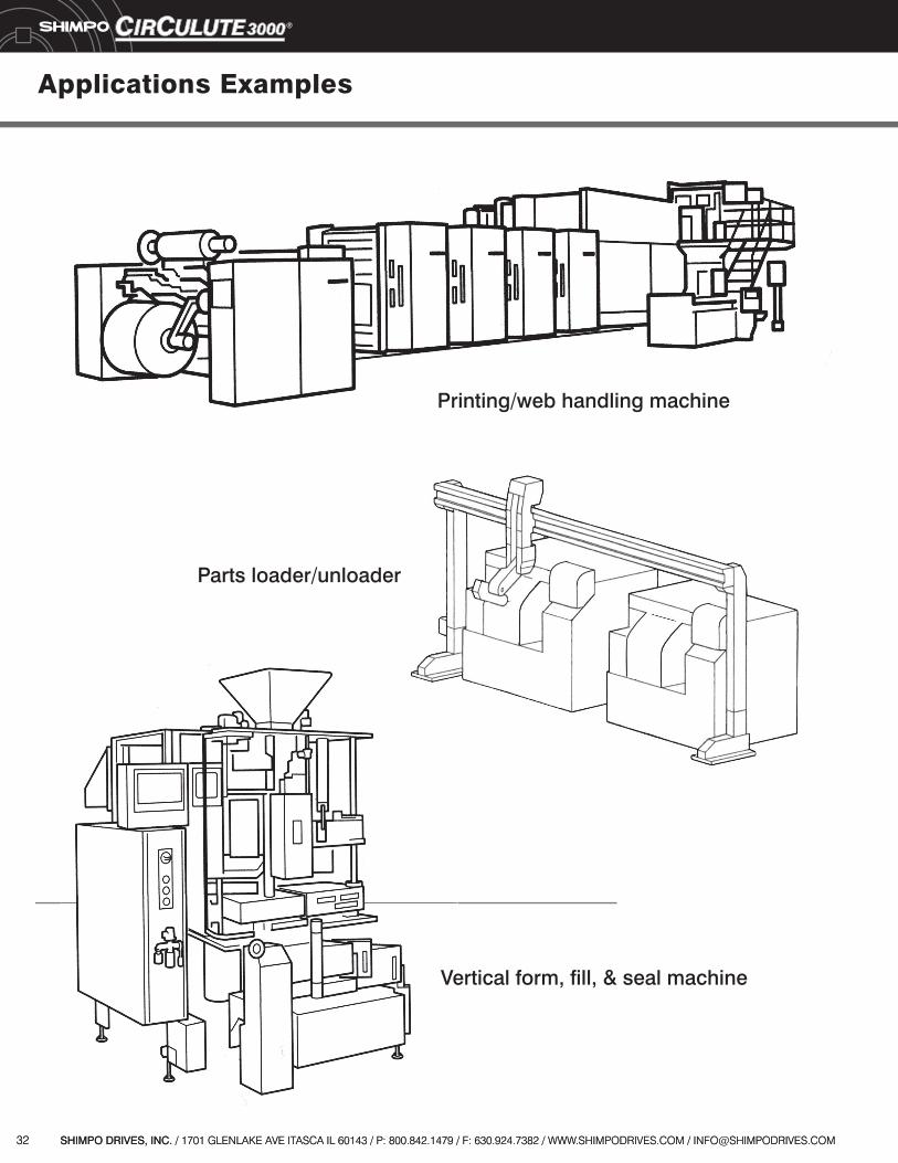
32 SHIMPO DRIVES, INC. / 1701 GLENLAKE AVE ITASCA IL 60143 / P: 800.842.1479 / F: 630.924.7382 / WWW.SHIMPODRIVES.COM / [email protected]
Applications Examples
Vertical form, fill, & seal machine
32 SHIMPO DRIVES, INC. / 1701 GLENLAKE AVE ITASCA IL 60143 / P: 800.842.1479 / F: 630.924.7382 / WWW.SHIMPODRIVES.COM / [email protected]
Parts loader/unloader
Printing/web handling machine
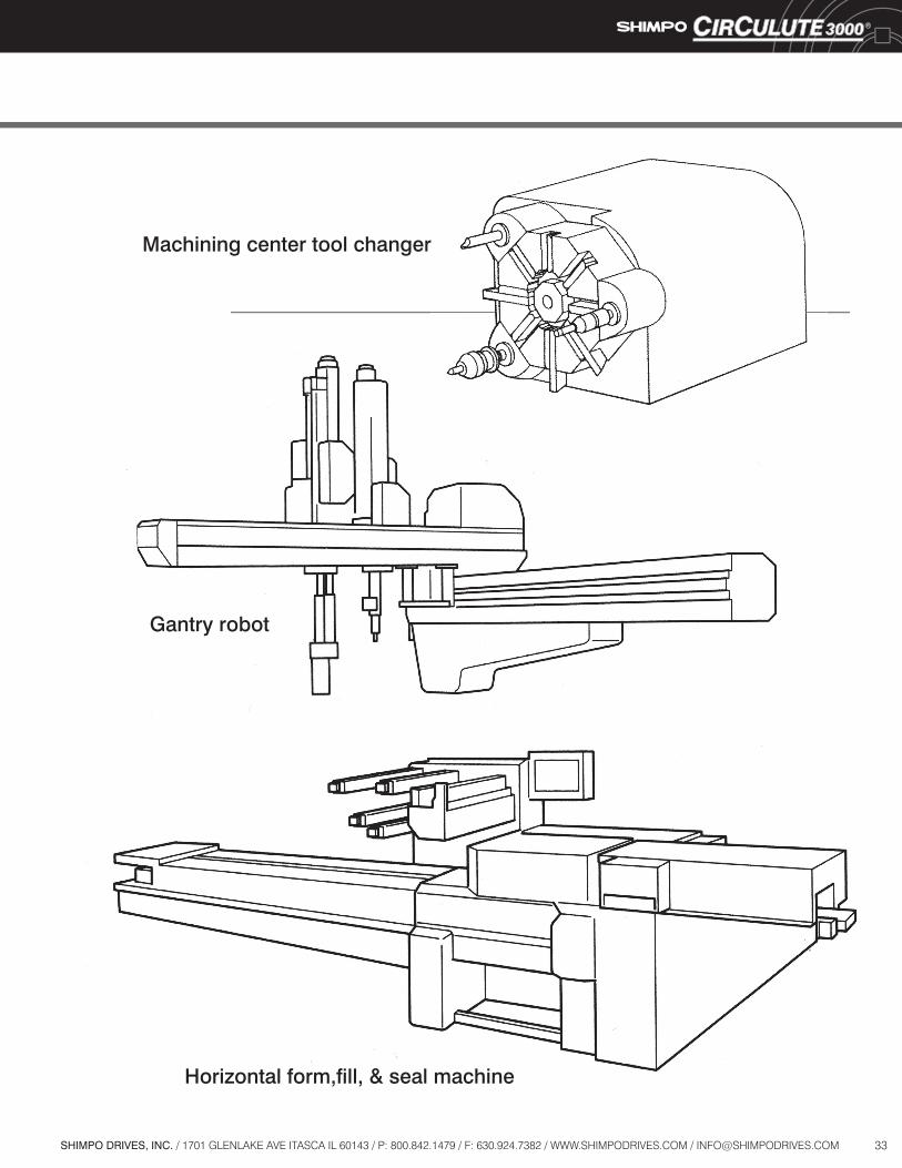
33SHIMPO DRIVES, INC. / 1701 GLENLAKE AVE ITASCA IL 60143 / P: 800.842.1479 / F: 630.924.7382 / WWW.SHIMPODRIVES.COM / [email protected]
Gantry robot
Machining center tool changer
Horizontal form,fill, & seal machine

Introducing SHIMPO's Circulute Pulley
Circulute Pulley, Flange Mount
Circulute Pulley w/Hollow Shaft
Shaft Input w/Hollow Shaft Output
C-Face Input w/Hollow Shaft
In addition to our standard assembly configurations,
the is also available with an
integral pulley, with a hollow output shaft, or
both. These configurations, available in three
sizes, can be used in a number of situations
to create a compact footless drive package.
Available in the followingconfigurations:
For more information, see our brochure with
full specifications and dimensions.

Shimpo’s North American headquarters is in suburban Chicago where we inventory, provide sales, engineering, and product support.1
Shimpo’s corporate offices are in Japan where the company performs product research, development, and international sales support. ISO 9001 certified.4
3
1
34
SHIMPO Worldwide Facilities
Shimpo’s state-of-the-art factory and sales office in China combine to fill out a major presence throughout Asia.
22
Shimpo’s Regional offices are located in California and North Carolina, providing sales, engineering, and product support.2
5
Shimpo’s European presence is represented by a sales office in Germany.5
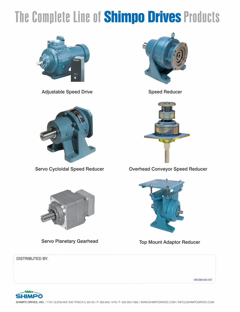
DISTRIBUTED BY:
Adjustable Speed Drive Speed Reducer
Top Mount Adaptor Reducer
Servo Cycloidal Speed Reducer Overhead Conveyor Speed Reducer
The Complete Line of Shimpo Drives Prod ucts
SHIMPO DRIVES, INC. / 1701 GLENLAKE AVE ITASCA IL 60143 / P: 800.842.1479 / F: 630.924.7382 / WWW.SHIMPODRIVES.COM / [email protected]
CIRC3000.002.0707
Servo Planetary Gearhead


