F SERIES PARALLEL SHAFT HELICAL GEAR REDUCERgear-reducer.org/pdf/f.pdf · Parallel shaft helical...
22
F SERIES PARALLEL SHAFT HELICAL GEAR REDUCER
Transcript of F SERIES PARALLEL SHAFT HELICAL GEAR REDUCERgear-reducer.org/pdf/f.pdf · Parallel shaft helical...
F SERIES PARALLEL SHAFT HELICALGEAR REDUCER
Characteristics:
Working Environment:
Instructions for Selection:
Op
era
ting
Mo
de
Fa
cto
r fA
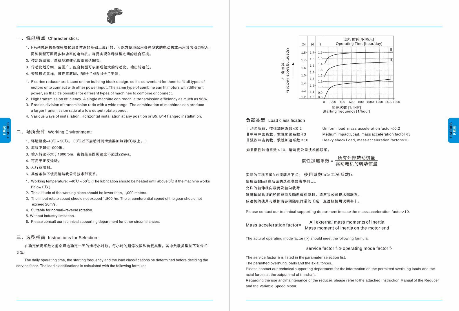
[ / ]Operating Time [hour/day]24
1.8
1.7
1.6
1.5
1.4
1.3
1.2
16
1.7
1.6
1.5
1.4
1.3
1.2
1.1
1.0
8
1.6
1.5
1.4
1.3
1.2
1.1
1.0
0.9
0.8
0 200 400 600 800 1000 1200 1400 1500
0.2
3
10
Load classification
Uniform load, mass acceleration factor 0.2
Medium lmpact Load, mass acceleration factor 3
Heavy shock Load, mass acceleration factor 10
10
=
fA
fB
fB fA
Please contact our technical supporting department in case the mass acceleration factor>10.
Mass acceleration factor=All external mass moments of Inertia
Mass moment of inertia on the motor end
The actural operating mode factor (fA) should meet the following formula:
service factor fB operating mode factor fA
The service factor fB is listed in the parameter selection list.
The permitted overhung loads and the axial forces.
Please contact our technical supporting department for the information on the permitted overhung loads and the
axial forces at the output end of the shaft.
Regarding the use and maintenance of the reducer, please refer to the attached Instruction Manual of the Reducer
and the Variable Speed Motor.
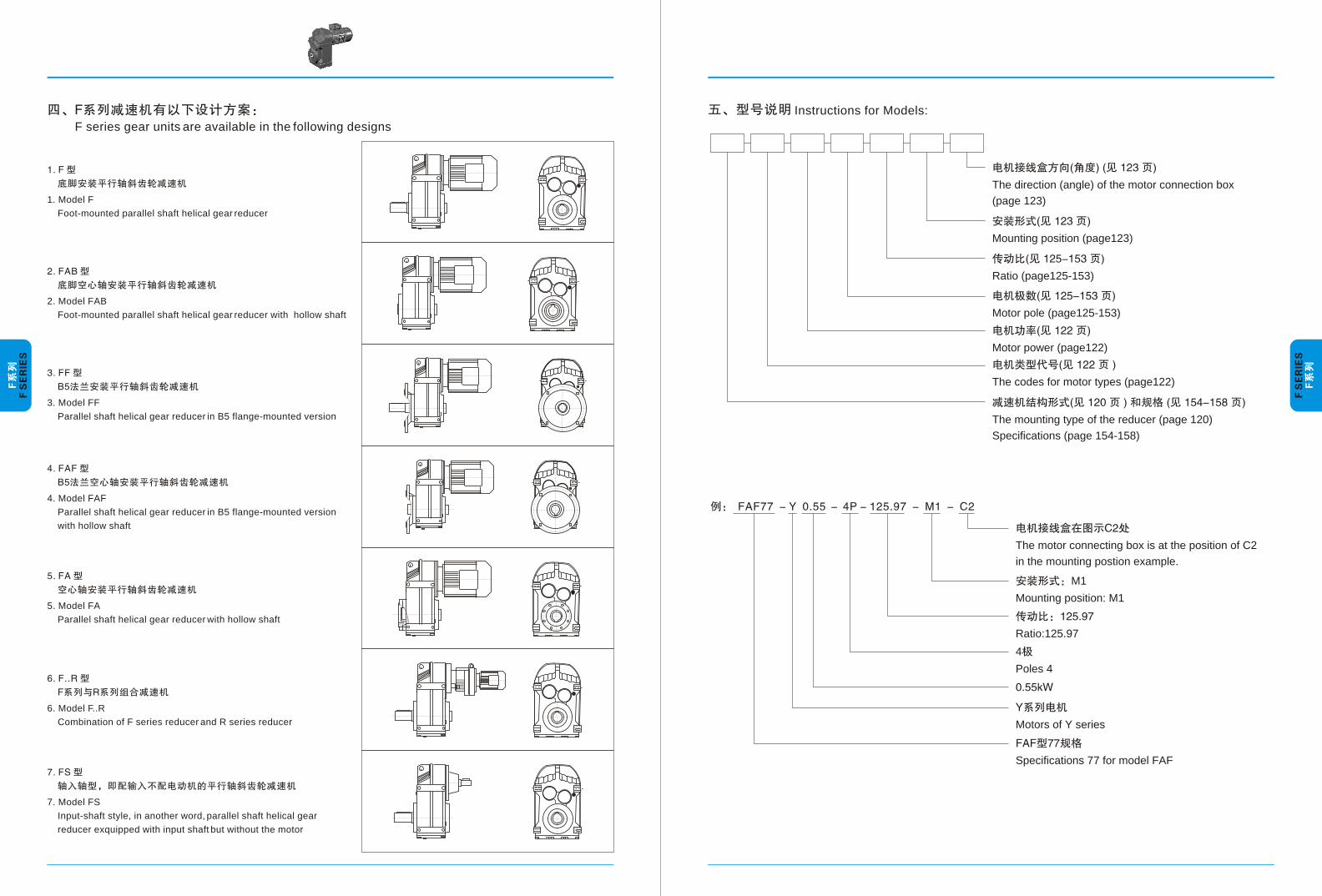
1. Model F
Foot-mounted parallel shaft helical gear reducer
2. Model FAB
Foot-mounted parallel shaft helical gear reducer with hollow shaft
3. Model FF
Parallel shaft helical gear reducer in B5 flange-mounted version
4. Model FAF
Parallel shaft helical gear reducer in B5 flange-mounted version
with hollow shaft
5. Model FA
Parallel shaft helical gear reducer with hollow shaft
6. Model F..R
Combination of F series reducer and R series reducer
7. Model FS
Input-shaft style, in another word, parallel shaft helical gear
reducer exquipped with input shaft but without the motor
F series gear units are available in the following designs
Instructions for Models:
The direction (angle) of the motor connection box
(page 123)
Mounting position (page123)
Ratio (page125-153)
Motor pole (page125-153)
Motor power (page122)
The codes for motor types (page122)
The mounting type of the reducer (page 120)
Specifications (page 154-158)
The motor connecting box is at the position of C2
in the mounting postion example.
M1
Mounting position: M1
Ratio:125.97
4
Poles 4
Motors of Y series
Specifications 77 for model FAF
Wobbling Oil drainOil filler
Y
Y series
Bake Motor
Increased Safety Motor
Codes for Motor Types:
Y
YEJ
A
Flame-proof Motor
Roll Motor
YB
YG
VE
Direct Current Motor
Variable Frequency Motor
Z
YVP
ZP
Explanation of mounting position example
Oil well
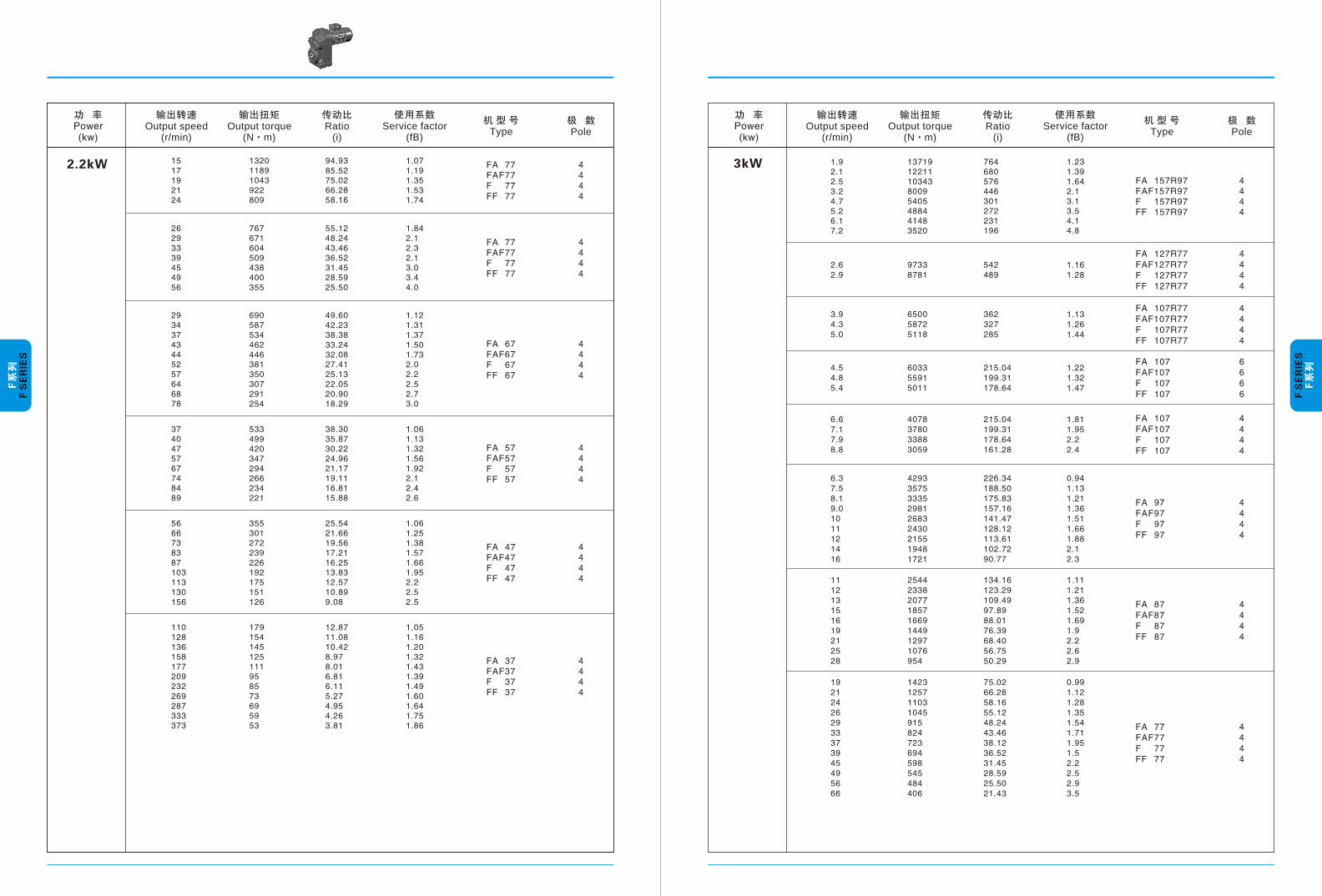
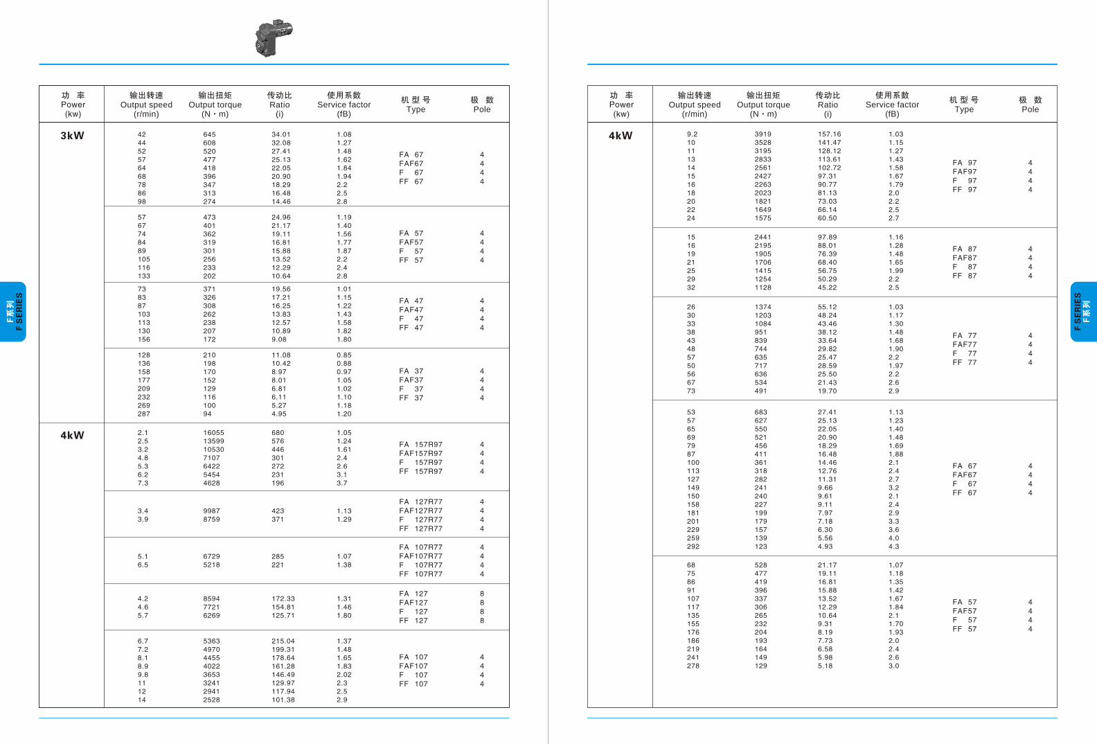
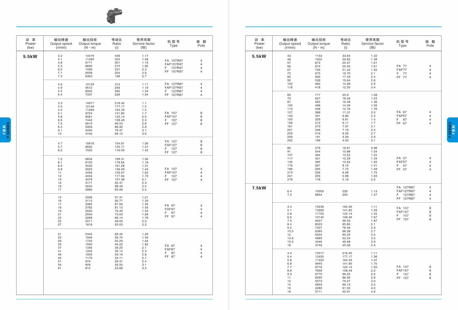
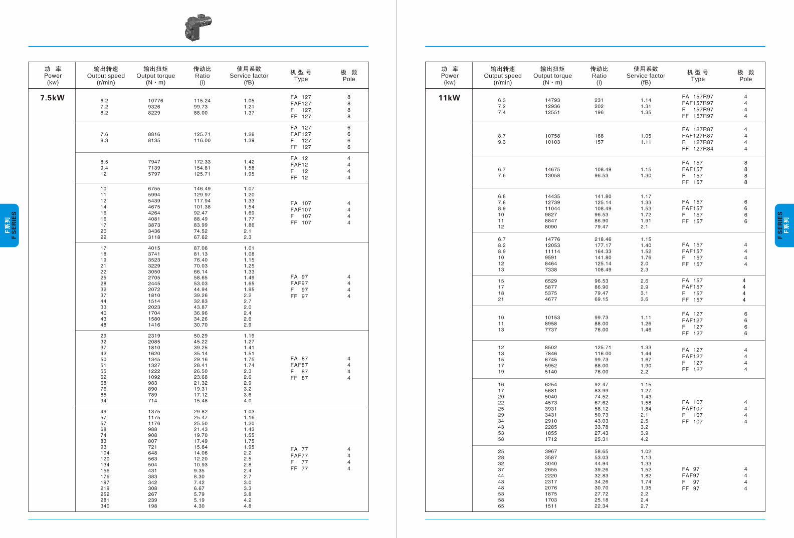
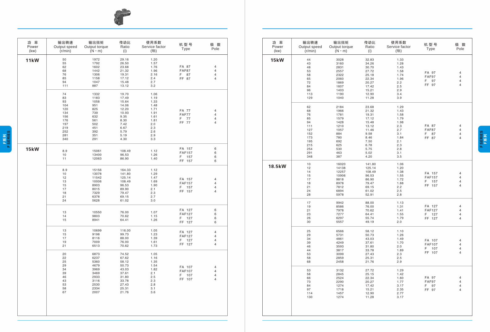
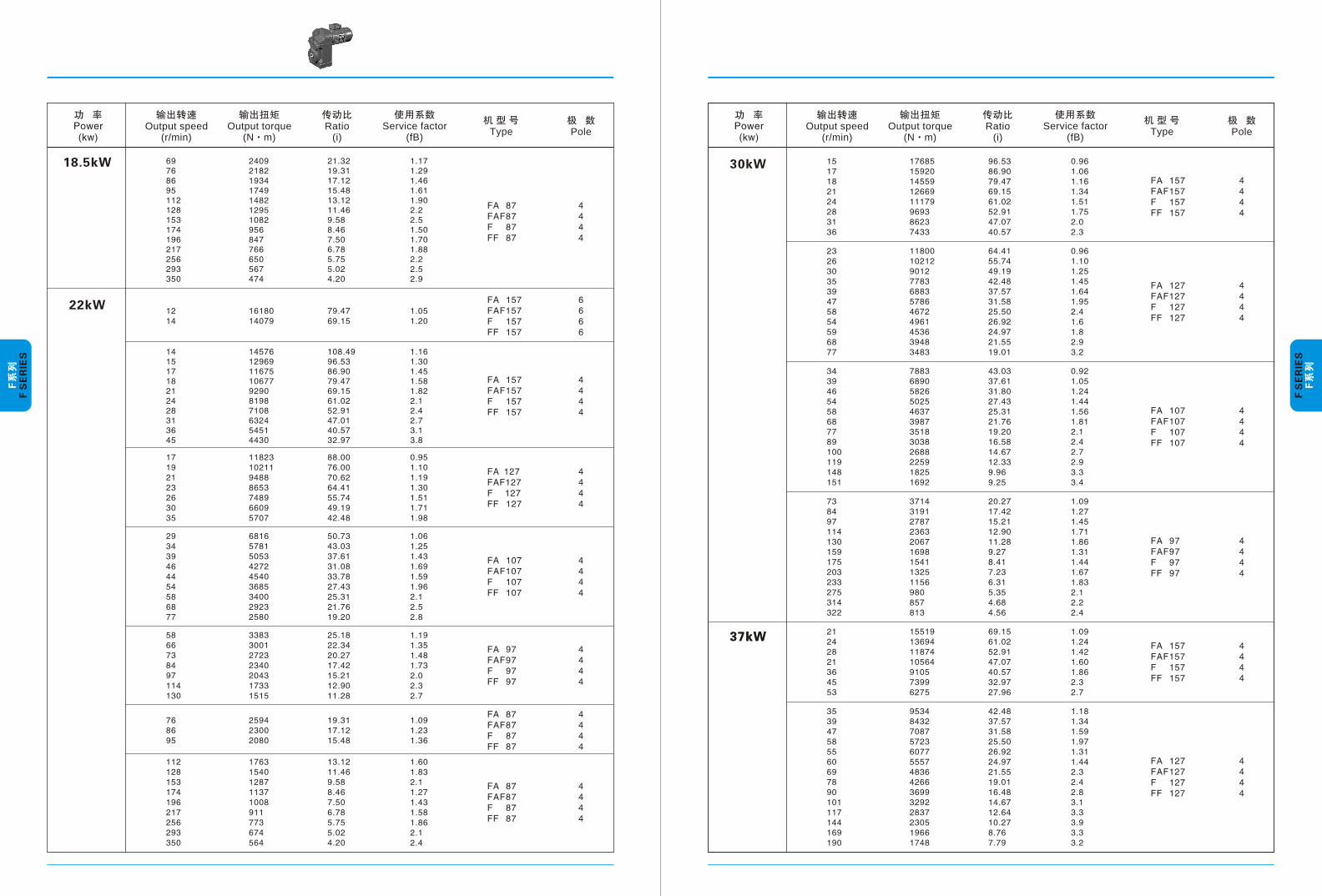
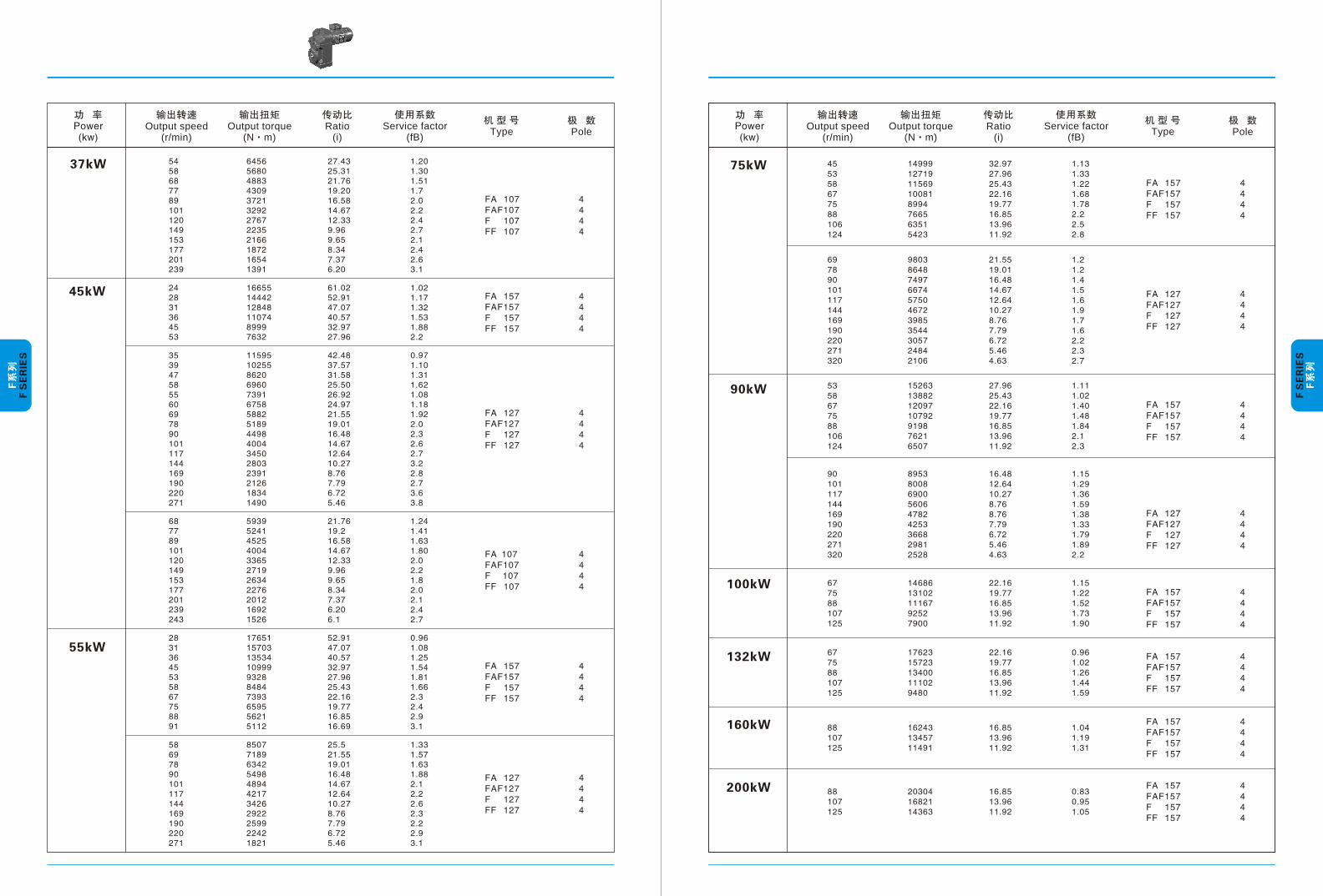
Explanation of Parameter Selection List
Power
(kW)
Output speed
(r/min)
Output torque
(N m)
Ratio
(i)
Service factor
(fB)
Type Motor pole
4.4
4.8
5.4
6.4
7.1
1603
1500
1300
1120
990
209.69
193.13
165.89
144.60
129.98
0.89
0.95
1.08
1.27
1.41
F 77
FF 77
FA 77
FAF77
6P
6P
6P
6P
6P
1. The machine types in the parameter selection list can match any transmission ratio in the column.
2. The parameters in this list also fits model FAB.
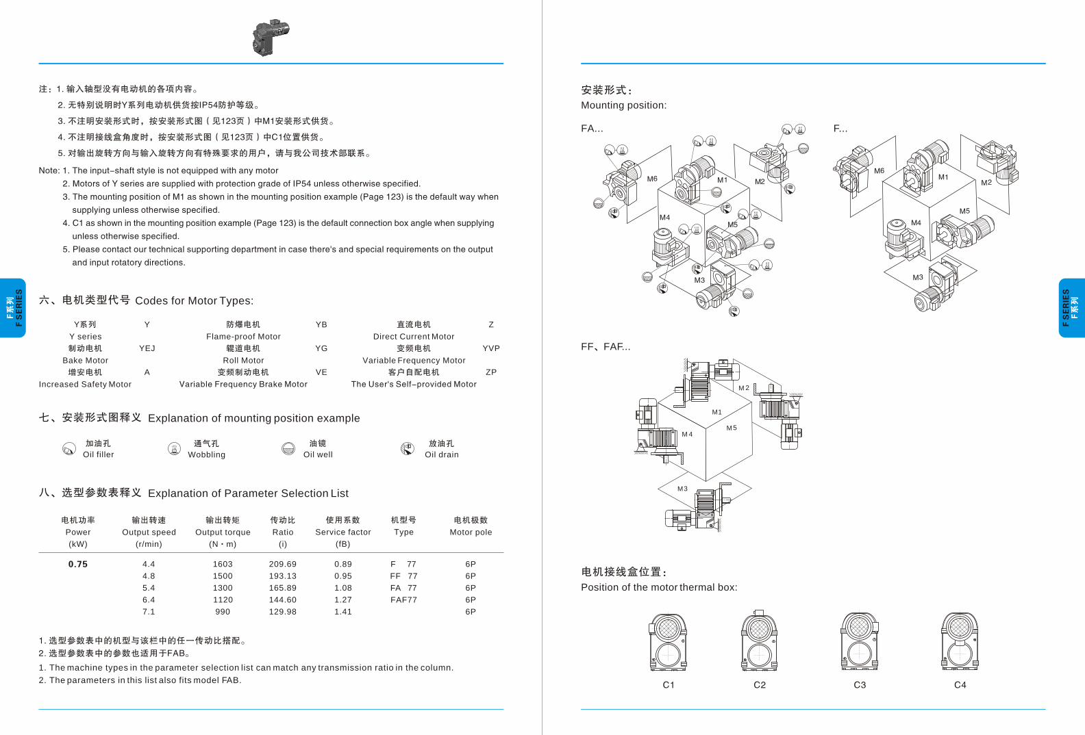
M 5
M1
M 2
M 4
M3
Mounting position:
Position of the motor thermal box:
FA... F...
FF FAF...
Weight(kg)
Type
Input power rating and permissible torque
Reducer weight
Gear unit type
Structure
Ratio
The weights are mean values, only for reference.
Lubrication table
Fill quantity in liters
Output speed(r/min)
Ratio(i)
Service factor(fB)
Type
Pole
Output torque(N m)
Gear unit type
Output speed(r/min)
Ratio(i)
Service factor(fB)
Type
Pole
Output torque(N m)
Output speed(r/min)
Ratio(i)
Service factor(fB)
Type
Pole
Output torque(N m)
Output speed(r/min)
Ratio(i)
Service factor(fB)
Type
Pole
Output torque(N m)
Output speed(r/min)
Ratio(i)
Service factor(fB)
Type
Pole
Output torque(N m)
Output speed(r/min)
Ratio(i)
Service factor(fB)
Type
Pole
Output torque(N m)
Output speed(r/min)
Ratio(i)
Service factor(fB)
Type
Pole
Output torque(N m)
Output speed(r/min)
Ratio(i)
Service factor(fB)
Type
Pole
Output torque(N m)
Output speed(r/min)
Ratio(i)
Service factor(fB)
Type
Pole
Output torque(N m)
Output speed(r/min)
Ratio(i)
Service factor(fB)
Type
Pole
Output torque(N m)
Output speed(r/min)
Ratio(i)
Service factor(fB)
Type
Pole
Output torque(N m)
Output speed(r/min)
Ratio(i)
Service factor(fB)
Type
Pole
Output torque(N m)
Output speed(r/min)
Ratio(i)
Service factor(fB)
Type
Pole
Output torque(N m)
Output speed(r/min)
Ratio(i)
Service factor(fB)
Type
Pole
Output torque(N m)
Output speed(r/min)
Ratio(i)
Service factor(fB)
Type
Pole
Output torque(N m)
Output speed(r/min)
Ratio(i)
Service factor(fB)
Type
Pole
Output torque(N m)
Output speed(r/min)
Ratio(i)
Service factor(fB)
Type
Pole
Output torque(N m)
Output speed(r/min)
Ratio(i)
Service factor(fB)
Type
Pole
Output torque(N m)
Output speed(r/min)
Ratio(i)
Service factor(fB)
Type
Pole
Output torque(N m)
Output speed(r/min)
Ratio(i)
Service factor(fB)
Type
Pole
Output torque(N m)
Output speed(r/min)
Ratio(i)
Service factor(fB)
Type
Pole
Output torque(N m)
Output speed(r/min)
Ratio(i)
Service factor(fB)
Type
Pole
Output torque(N m)
Output speed(r/min)
Ratio(i)
Service factor(fB)
Type
Pole
Output torque(N m)
Output speed(r/min)
Ratio(i)
Service factor(fB)
Type
Pole
Output torque(N m)
Output speed(r/min)
Ratio(i)
Service factor(fB)
Type
Pole
Output torque(N m)
Output speed(r/min)
Ratio(i)
Service factor(fB)
Type
Pole
Output torque(N m)
Output speed(r/min)
Ratio(i)
Service factor(fB)
Type
Pole
Output torque(N m)
Output speed(r/min)
Ratio(i)
Service factor(fB)
Type
Pole
Output torque(N m)
Output speed(r/min)
Ratio(i)
Service factor(fB)
Type
Pole
Output torque(N m)
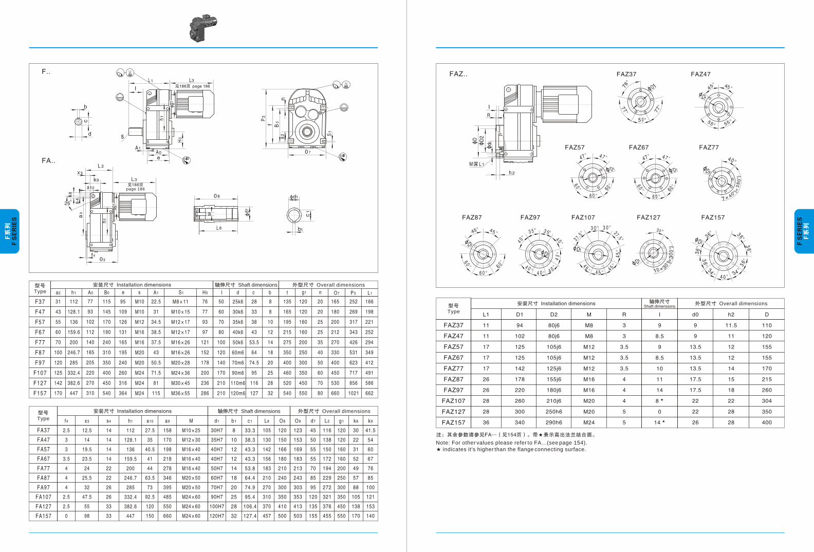
page 186
Type
Shaft dimensions Overall dimensions
Type
Shaft dimensions Overall dimensions
TypeShaft dimensions
Overall dimensions
Note: For other values please refer to FA...(see page 154). indicates it's higher than the flange connecting surface.
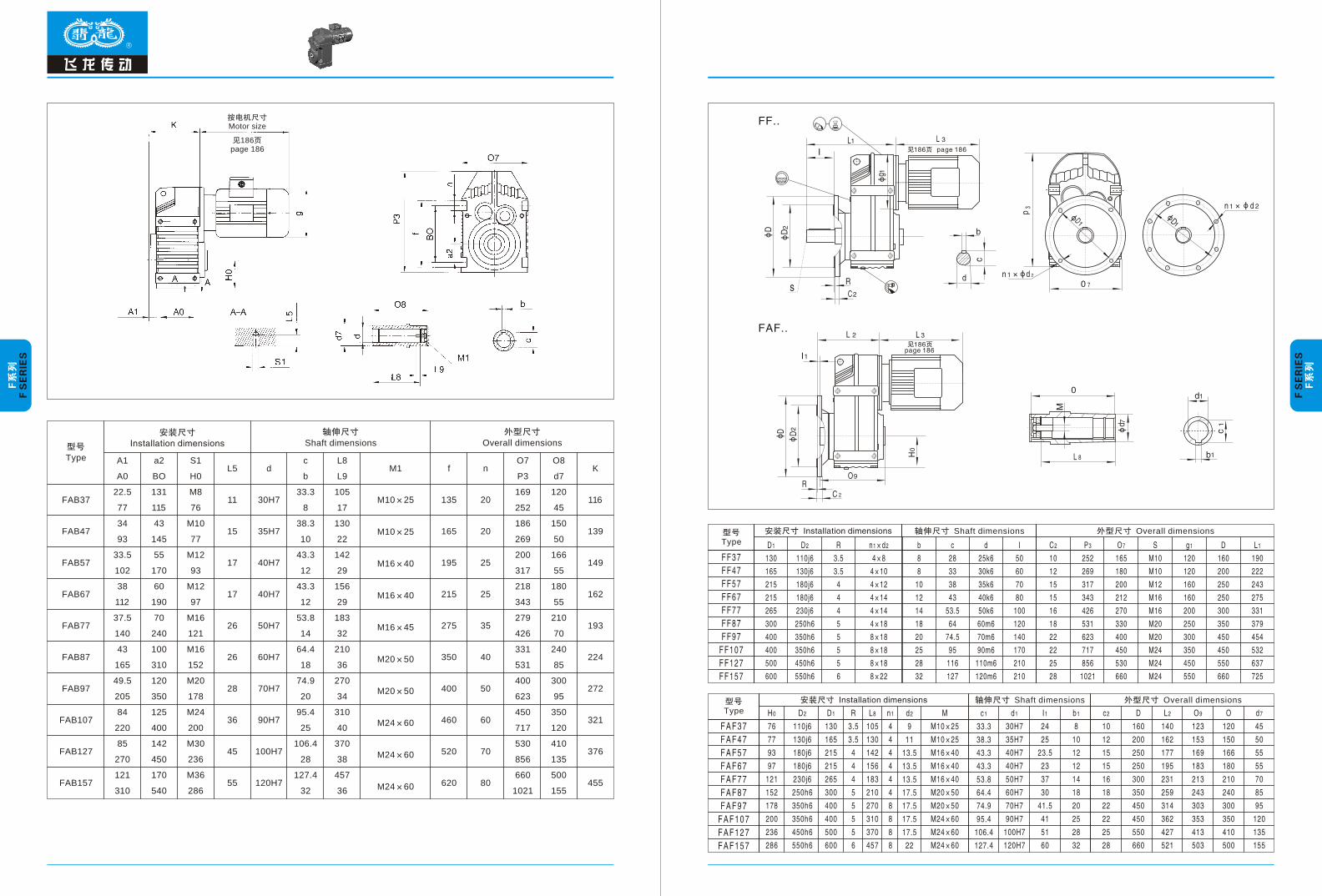
Motor size
186page 186
Type
Shaft dimensions Overall dimensions
FAB37
FAB47
FAB57
FAB67
FAB77
FAB87
FAB97
FAB107
FAB127
FAB157
A1
A0
22.5
77
34
93
33.5
102
38
112
37.5
140
43
165
49.5
205
84
220
85
270
121
310
a2
BO
131
115
43
145
55
170
60
190
70
240
100
310
120
350
125
400
142
450
170
540
S1
H0
M8
76
M10
77
M12
93
M12
97
M16
121
M16
152
M20
178
M24
200
M30
236
M36
286
L5
11
15
17
17
26
26
28
36
45
55
d
30H7
35H7
40H7
40H7
50H7
60H7
70H7
90H7
100H7
120H7
c
b
33.3
8
38.3
10
43.3
12
43.3
12
53.8
14
64.4
18
74.9
20
95.4
25
106.4
28
127.4
32
L8
L9
105
17
130
22
142
29
156
29
183
32
210
36
270
34
310
40
370
38
457
36
M1
M10 25
M10 25
M16 40
M16 40
M16 45
M20 50
M20 50
M24 60
M24 60
M24 60
n
20
20
25
25
35
40
50
60
70
80
O7
P3
169
252
186
269
200
317
218
343
279
426
331
531
400
623
450
717
530
856
660
1021
O8
d7
120
45
150
50
166
55
180
55
210
70
240
85
300
95
350
120
410
135
500
155
f
135
165
195
215
275
350
400
460
520
620
K
116
139
149
162
193
224
272
321
376
455
Shaft dimensions Overall dimensions
Type
Shaft dimensions Overall dimensions
Type
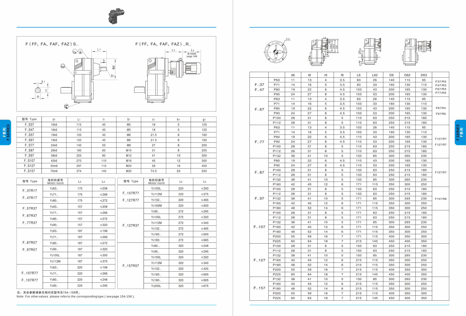
n-s
r6
d6
t6
L6
62
f6
D6
3D
62
D6
Motor norm
Type
TypeMotor norm
Type
Note: For other values please refer to the corresponding type ( see page 154-156 ).