The Embodiment Design of the Heat Rejection System for the ...
51
NASA-CR-197178 NASw-4435 /' /'y -" 4" "'" The Embodiment Design of the Heat Rejection System for the Portable Life Support System Group Members: Group Leader: Sue Stuckwbch Carlos A. Carrion, Jason Francois, Julia Laughlin, Lee Phillips. April 25, 1994 (NASA-CR-19717B) THE EMBODIMENT DFSIGN OF IHE HEAT REJECTION SYSTEM FOR THE PORTABLE LIFE SUPPORT SYSTEM (USRA) 51 p N95-12S55 Unclas G3/54 0026154
Transcript of The Embodiment Design of the Heat Rejection System for the ...

NASA-CR-197178
NASw-4435
/' /'y -" 4" "'"
The Embodiment Design of the Heat Rejection
System for the Portable Life Support System
Group Members:
Group Leader: Sue Stuckwbch
Carlos A. Carrion, Jason Francois, Julia Laughlin, Lee Phillips.
April 25, 1994
(NASA-CR-19717B) THE EMBODIMENT
DFSIGN OF IHE HEAT REJECTION SYSTEM
FOR THE PORTABLE LIFE SUPPORT
SYSTEM (USRA) 51 p
N95-12S55
Unclas
G3/54 0026154

The Embodiment Design of the Heat Rejection
System for the Portable Life Support System
Group Members:
Group Leader:. Sue Stuckwisch
Carlos A. Carrion, Jason Francois, Julia Laughlin. Lee Phillips
April 2S, 1994
The Portable Life Suppon System (PLSS) provides a suitable en_nronment for the
astronaut in the Extravehioulm" Mobility Unit (EML_, and the heat rejection systemcontrols the thermal conditions in the space suit. The current PLS$ sublimates water tothe space envLronment; therefore, the systems loses mass. Since _ditional supplies offluid must be available on the Space Shuttle, NASA desires a closed he_ rejecting system.
This document presents the embodimem design for a radiative plate heat rejection systemwithout mass transfer to the space enviromnent. This project will transform the conceptvariant into a design complete with material selection, dimensions of the system, layouts ofthe heat rejection system, suggestions for manufacturing, and financial viability.

The Embodiment Design of the Heat Rejection
System for the Portable Life Support System
Group Members:
Group Leader:. SueStuckwischCarlos A. Carrion, Jason Francois, Julia Laughlin, Lee Phillips
April 25, 1994

Scope and Limitations
Background and Clarification of Task
The Portable Life Support System (PLSS) is part of the Extravehicular Mobility
Unit (EMU) that provides xhermal control of the space suit environment and o_gen to the
astronaut. A heat rejection system is used to cool the Space Suit Assembly (SSA). Fluid
circulates through a Liquid Cooled Ventilation Garment (LCVG) worn by the astronaut to
absorb heat fi'om the astronaut's body, and the heated fluid is carried to the PLSS.
Depending on the temperature of the fluid, the fluid takes a path to either the heating
system or the cooling system.
The current system uses a heat exchanger to cool the circulating fluid and a
sublimator that rejects heat to the environment. As the heated water circulates to the heat
exchanger and sublimator, heat is transferred through the aluminum wall to the porous
wall. Ice forms in the pores of the wall and is sublimated by the heat absorbed in the walls
into a gas. Water vapor travels through the pores and into space (Vogt, p. 15). The heat
transfer rate of the sublimator is dependent on the metabolic rate of the astronaut. As the
work load increases, the amount of heat absorbed into the cooling fluid increases. As a
result, the ice is sublimated more rapidly, and heat can be removed from the system at a
greater rate (Vogt, p. 17). Since a portion of the fluid is evaporated to the space
environment, fluid is depleted from the system. As a result, a new supply of fluid must be
provided. Since additional supplies of fluid must be maintained and recharging is
necessary, NASA desires a closed system heat rejecting unit that does not require
regeneration between Extra-vehicular Activities (EVAs). A closed system decreases the
amount of cooling materials that must be transported for each space mission. The task is
to embody the heat rejection system for the PLSS. The system must meet the
specifications and functional requirements provided to the design team. The specification
appem in peadix A.Previously, a design team developed two concept v,,,-iants as solutions for the
closed heat rejection system. One heat rejection system is a multiple radiative plate array,
and the other system is a phase change heat sink. The first step in this project is to
determine which of these two concept variants should be embodied for final design. This
project will transform an abstract concept idea into a concrete design complete with
material selection, dimensions of the unit, layouts of the beat rejection system, suggestions
for manufacturing and financial viability. In addition, more information is acquired to

pro',ide details of the design and to complete the unfinished tasks of the conceptual design
of the heat rejection system.
The scope of this project includes the embodiment of the heat rejection plate but
not the sub-systems which support the heat rejection system. These subsystems include
the pump to circulate the fluid through the $SA and the PLSS, temperature sensors,
malfunctionin 8 signals, backup systems, valves, batteries, and the fluid transfer system
be_een the pump and the heat rejection system. Since there is a separate system to
provide heat to the astronaut during body temperature drops, the heating system will not
be considered in the scope of this paper. Although perspiration introduces moisture into
the system, a system to remove the moisture will not be included in this project.
Radiative Plate vs. Heat Sink
The two concept variants given for the PLSS system are shown in Figures I and 2.
Figure 1 illustrates the radiative plate. The radiative plate consists of a flat plate or array
of plates with multiple fins. The fins are attached to increase the surface area in order to
provide more radiative heat transfer. The plate has tubes with a cooling fluid running
through its interior. As the fluid passes through the plate, the heat that was absorbed in
the fluid while traveling across the astronaut's body is convected from the fluid, conducted
through the plate, and then radiated out into space. The phase change heat sink is shown
in Figure 2. The heat sink contains a storage container packed v, ith a bed of ice spheres.
As the fluid coming from the LCVG flows through the packed bed, the heat stored in this
fluid is transferred to the ice which cools the liquid.
Heatedfluid In
Fipre I. I_diati_e Plate C_.ep_u_l, _ (Boureil)

°°'° Yno o
0 o00 0
Refreezablespheres outof Ice
Cooled
__D,, fluldout
Fi|ure 2. Heat Sink Conceptual Desisn (Bourell)
Several calculations were performed to determine which aOncept variant, should be
chosen (Appendix B). The amount of heat that must be removed is lnsed on the
metabolic rate of the astronaut. For the phase change h¢_ _ the mass of ice required
to remove this quantity of heat was calculated. From the,_:alculations, the required
amount of ice exceeds the desired rna,sr,-constraint chat National Aeronautics and Space
e,,clrninistrafion (NASA) imposed by T0%. _ order to determine if the radiative plate is
feasible, the surface area that would be needed to remove the heat was calculated. It was
determined there is a range for the surfaur,e area that fits within the dimension constraints.
Based on these calculations, the radiative plate is the better choice for embodiment.
Several additioml factors affected the decision between the embodiment of the
radiative plate md ice spheres. The radiative plate contains fewer components compared
to the heat sink. The heat sink would require a more complicated manufacturing process
because the heat rejection unit must contm the ice balls, and the ice l_Ols :eq_ires
steps to produce. In order to prevent the ice balls fi'om moving around within the
radiative system, the rrumufacturing processes will require fighter manufacturing
tolerances. Due to the complexity of the design of the heat sink, the system is more likely
to malfimction. The estimated cost for the heat _ would be much greater than the
radiative plate because the heat sink requires more components, more detailed
manufacturing process, more materials, and a regeneration method to refreeze the ice
balls.

' .-Xdecision matrix v_as created in order to ,,erif), ,._,hich design should be embodied
Appendix C shows the binary matrix which determines the weights for the categories the
decision is based. Figure 3 illustrates the decision matrix vvhich concluded that the
radiative plate is the better choice; therefore, this concept variant will be taken through the
embodiment stage
Heat Sink
Radiati,-:
Plate
Capacl_ toAbsorb Heat
43%
Time Constant
29%
Mass
14%Complexity
14%
Total
Figure 3. Decision Matrix for Concept Variants
Design Issues
There are several design issues which must be considered prior to the embodiment
of the radiative plate. The peak metabolic rates and heat entering from the environment by
absorption must be considered. When selectin 8 materials, the radiative properties must be
examined. The system should be able to maintain the atmosphere of the EMU between
294 K and 300 K (21" C and 27°C). This temperature ranse provides a comfortable
environment for the utmn_ (Barry, p. 372). In order to maintain the temperature, the
system must not absorb more heat than is required to mainuun the fluid between the
comfortable temperature ranges. If the system absorbs more heat than needs to be
radiated, a heating system will be required to work in conjunction with the cooling system.
The circulating fluid should have adequate convective properties to absorb heat from the
astronaut. The heat rejection system should be made of a material that can absorb the heat
from the fluid and radiate the heat to the environment. The acceptable amount of time or
time constant for heat to be released to the environment depends on the period of time
before the environment of the EMU reaches a dangerous ambient temperature of 310 K

tBar_', p ._,-) The system must be a closed system v_ith no mass loss to the
en,,ironment, and the system should not require regeneration or recharging after the
Extravehicular Activity (EVA).
Functional Description
Embodiment Determining Requirements
The following is a list of criteria that will be used to evaluate the embodiment and
aid in the determination of final dimensions of the system based on the provided
specifications:
• Heat rejection capacity
• Operation for the duration of EVA
• Geometrical constraints
• Impact strength
• Mass
The heat rejection capacity of the radiative plate will be analyzed in the
embodiment of the heat rejection system because the primary function of the radiative
plate is to reject heat from the fluid flowing through the plate. The radiative plate must
reject the average metabolic rate for a six hour EVA and account for metabolic peaks
during EVA. The material of the radiative plate must absorb the heat from the cooling
fluid and store any heat that cannot be immediately radiated from the system_ The material
of the radiative plate must have thermal properties that will conduct and radiate the heat
that is convected in the fluid. The important properties of the radiative plate material are
the density, the specific heat, conductivity, emissivity, and absorptivits,. The material
must create a blackbody with high emissivity and low absorptivity (Purser, p. 145). If the
radiative plate can accommodate these factors, the astronaut will not become overheated,
and the heatrejection systemwill fulfill the l_tional requirements.
Since the longest EVA missions last for six hours, the radiative plate must reject
the aventge metabolic rate for this time period. In addition, a heat rejection system that
can be used in longer EVA missions required dutin 8 space station construction is of
interest to NASA.
Due to safety factors and ersonometri¢ considerations, the PLSS cannot extend
more than 0.17 m from the astronauts back. As a result, the radiative plate is subject to
the size constraints of the PLSS. The heat rejection system can only use sixty percent or
6

0 l lm 3of the PLSS ,,olume The surface area of the radiative plate must be large enough
to radiate the heat produced by' the astronaut from the system.
Because impacts occur between space objects and micrometeoroids and other
objects such as structures of the space shuttle, the radiative plate must be able to
withstand impacts of 89 N If the heat rejection system cannot withstand these impacts,
the system may become damaged and may harm the astronaut.
Since this heat rejection system may be used in the future for planetary missions,
the mass of the system should be small enough so that the weight of the system in gravity
environments is not a burden on the astronaut carrying the PLSS. Increasing thermal
capacitanceby increasingthemass oftheplateallowsheattobe storedduringpeak
metabolicperiods.However, themass shouldbe constrainedtopreventabsorptionof
more heatthancanbe radiatedfora certainmetabolicrate.Inaddition,thecostof
transportingthesystemto spaceincreasesasmass ofthesystemincreases.
Thereareseveralimportantfactorsintheembodiment thatwere notincludedin
thespecificationssheetshown inAppendixC. The timeresponseofthesystemdictates
how quicklyheatcanbe rejectedfrom thesystemand thetimeforsteadystatetobe
reachedduringmetabolicpeaks.Duringthesepeaks,theheatrejectionsystemcannot
rejectalloftheheatthathasbeenabsorbed.Ifthesystemcannotreachequilibrium,the
platewillcontinuetoheatup and thecoolingfluidwillheatup becausetheplatewillno
longerabsorbheat.As a result,thesystemwillno longercooltheastronaut.On the
otherhand,to preventtheastronautfrombecoming cold,theradiativeplateshouldnot
absorbtoomuch hem. A power sourceforthesystemshouldbe adeclu_etoruntheheat
rejectionsystemforsixhoursand operatethesubsystemssuchasthepumps, valves,and
thermocouples.The power sourcemust be independentofthespace shuttlebecausea
power cordbetweenthePLSS and theshuttlewould restrictthedistancerangebetween
theastronautand theSpice Shuttle.The pump shouldhandlethemass flowsrequiredto
producethenecx_uuu'yflowratesand healrejectionrates,butthepower requirementof
the pump is limited by the capabilities of the power source. The pump needsto provide a
suf6cient pressuregradient to move the fluid through the system. The corrosive
properties of the radiative plate shouldbe considered. The radiative plate shouldbe
composed of a material that does not corrode while in contact with the cooling fluid.
Corrosion affects the life and the reliability of the system, and corrosion could contaminate
the fluid and the system.

Functional Description
The function structure gb,en in Figure 4 gives the sub functions of the heat
rejection unit for the PLSS. The heat rejection unit must accommodate each function
either by individual devices or through function sharing. Some of these functions will be
handled with subsystems that are not a part of the radiative plates and out of'the scope of
this project. These functions include collecting and storing energy, providing power to the
back up system, measuring body temperature, and providing support.
The most important functions of the heat rejection system that must be taken into
account are: transfer fluid, control fluid, transfer heat, absorb heat, and protecting the
system from impacts and leaks. These subfunctions are imperative to the system because
if these functions are not properly performed, the entre system will not be able to keep the
astronaut cool. The system must transfer the fluid through the radiative plate and through
the LCVG. This function is important because the number of pipes and the pipe diameter
affect the mass and heat transfer capabilities of the system. Although it is notwithin the
scope of this project, valves will have to be designed for this purpose. By controlling the
mass flow of the fluid through the radiative plate, the amount of heat removed from the
system can be controlled. As a result, the problem of removing too much or too little heat
from the system is addressed, and the astronaut's body temperature can be maintained at a
comfortable temperature range. The radiative plate must transfer enough heat from the
cooling fluid to the exposed surface so the proper amount of heat can be radiated from the
system to the space environment. The radiative plate also needs to be able to absorb
enough heat to cool the astronaut at times of peak metabolic rates. A factor of safety is
included in the calculations in order to accommodate unc, eminfies in the analysis. The
thermal properties of the material determines the ability ofthe plate to absorb heat from
the convectingcooling fluid.
Embodimmt
DescHptiea ef E-,b_lied Design
According to Ul_um's procedure for embodiment design,afterdetermining the
product from the conceptual design different materials and production techniques should
be considered. The manufacturing methods wig determine the tolerances for the design.
Next, the spatial requirements and the geomeu7 of the system must be considered. The
radiative plate will consistof two plates connected to each other with tubes in between the
plates for the cooling fluid to flow. The plate wig require an insulator on the side facing
the astronaut's back in order to prevent heat transfer to the astronaut. An extermd coating

I
I
I
I
I
I
I
I
Energy
Astronaut
FailureWattling Coolant
I Pressure Leakage Warning ,I I Ruid Leakage Warning I I
I I I I
Provide PowerTransferFluid tO
Control Transfer Fluid toFlow Heat
I
I
ChilledI Coolant
BackupFluid
Body HeatSolar Flux
Figure 4. Function Structure (BoureII)

on the surface of the plate decreases the absorptivity of the radiative plate (_,Tiet) -_11
dimensions must meet NASA's specifications. The radii of the fillets and edges should be
included in the dimensioning of the plate. The properties of the plate, tubes, and fluid will
be analyzed on a separate basis in order to ma:,dmize overall results. The heat transfer,
mass flow rate, connection between the two plates, and reaction betw_n the fluid and the
plates, are examples of issues that must be considered because they effect the functions of
the components.
Once functional requirements are addressed, the material selected, the fluid chosen,
and the dimensions are made, the system is ready to be evaluated. The system is evaluated
according to projected product performance with respect to customer requirements. For
example, the amount of heat the system is capable of removing will be calculated and
compared to the amount of heat that must be removed. After evaluation, the system will
be refined until a quality design is produced.
An overall layout of the cooling system is shown in Figure 5. The figure illustrates
how the radiative plate interacts with some of its subsystems. The mass flow rate in the
radiative plate will be controlled by a subsystem containing a pump, valve, thermocouple,
and a pressure gauge. The pump will be driven by a motor and powered by a battery. A
device will be necessary to disperse the fluid into the pipes. Seals will be required to
prevent leakage from the system. A method for diverting flow when the fluid does not
need to be cooled will also be considered. For safety purposes, a signal that the system is
malfunctioning should be provided to warn the astronaut to return to the Shuttle.
Calculations Showin 8 Technical Feasibillt 7
The dimensions for the design of the radiative plate are based on the amount of
heat that has to be rejected by the system. By conservation of energy, the heat transferred
from the astmnaufs body to the liquid has to be tranfferred to the plate, and finally
radiated to space.
The amount of heat that needs to be rejected from the system is based on the
metabolic rate profile for a 6 hour mission as seen in Figure 6. The average metabolic rate
is 245 Watts. Table I shows the differential fluxes of the astronaut in a hot or a cold
environment. From thisvalue,the average differentialfluxhas to be subtracted,sincethe
differentialfluxrepresentsheatleavingthe suitwithout the assistanceof the heatrejection
system. In space missions,sunriseoccurs every 104 minutes with equaltime of darkness
and light; thus, the differential flux can be approximated as the average between the
values for hot and cold conditions (BoureiL p. 2). In addition, a factor of safety of 1.5 is
10

Pump and Motor _ j/_ Thermocc
Servo Valve
Battery _-E
In From_ LCVG
_- To LCVG -_---
Radiative Plate
pie
Radiative Coating
Figure 5. Overall layout for the embodied PLSS heat l_je_orl uniL
Table 1. Differential Flux (Bourell)
EnvironmentalConditions
Avg. Orbital Ruxes Avg. Orbital Ruxes(BTU/hr ft^2) (BTU/hr ft^2)
Differential Rux(BTU/hr)
Solar IRHot 144 85.2 70
Typical Modules 128 52.0 155Typical Truss 67 29.8 250
Cold 24 16.7 305

includedto accountfor possibledeviationsfrom thetypicalmetabolicrateprofile The
resulting value for the metabolic rate is 282 Watts.
The metabolic rate information is presented as heat (Watts), but for the purposes
of the heat transfer calculations we need to transform this heat into a heat flux (W/m 2)
To obtain a heat flux, the average metabolic rate is divided by the average human surface
area. This surface area is 2 2 m: (Woodson, p. 707). The resulting average heat flux is
128 W/m 2, and this value is used for the general heat transfer analysis.
In order to keep the astronaut at a comfortable temperature, the temperature of the
fluid leaving the heat exchanger has to be controlled. The temperature of the circulating
fluid supplied to the LCVG can be related to the metabolic heat rate by the following
equation, generated from experimental data by NASA-Johnson Space Center (Strumpf,
p. 2).
(l)
Where MR stands for the metabolic rate in Btu/hour. The results of this equation were
converted to temperatures in Kelvin.
The requiredfluidtemperature,derivedfrom the metabolicrateprofile(Figure6)
and Equation Iisshown as a functionof EVA time inFigure7. This figurepresents
instantaneoustemperaturerequiremems, and neglectsthe system thermallag. Inaddition,
Figure8 displaysthe inverserelationshipof metabolicrateand circulatingfluid
temperature. As the astronaut'smetabolicrateincreases,thetemperatureof the cooling
fluidmust decreaseto maintaincomfortabletemperaturelevels.For the metabolicrateof
282 Watts used inthe calculations,therequiredfluid supply temperatureis294 K.
The next step in the process is to calculate the change in the temperature of the
fluid as it flows through the LCVG The analysis for this calculation is based on the
asmmption that the hat flux is constant throughout the path followed by the fluid in the
LCVG. The expression used in the calculations is developed from an energy balance on a
control volume for internal flow in a pipe (lncroper_ p. 482).
a r =.¢' PL (2)tilCp
In this equation: q" = constant heat flux (W/m 2)
12

Metabolic Rate vs. EVA time
7O0
A
¢¢13¢
(D
¢¢1I:E
Oouu
OJO
(D
6OO
500
400
i
ri
300I
t
200 -_
0
100 -
0
Z
_,____-.
' ' ! ' i _ t ' ] " ]
1 2 3 4 5 6 7
Time (hours)
Figure 6. Metabolic Rate ProNe (Bourell)

Fluid Temperature EVA time
C=m
a)
_=
EQ,)
I,--
"10om
m
IJ-
297
296 -
295
294 -
293 --,
292 -
291
I
290 _i
--4
I
289t288
287 -
288
r
0 1 2
l
3
.-'L--
w
=.-:.-,
i ' 4
4 5
I
mL 3 ,-,_,-,,i 3,
I
6 7
Time (hours)
Figure 7. Temperature vs. EVA Time

Fluid Temperature Metabolic Rate
A
C
>m
_D
::3
¢¢1
CD
E
I.--
e,mlB
m
IL
297
296
295
294 -I
I
293 -
292 -]
291 -
2901
289
288
287
288
100
I ' t ' I
200 300 400
\\
\
500
\
\\
\,
\
i
F
600
Metabolic Rate (watts)

P = perimeter of each LCVG tube (m)
L = length of each LCVG tube (m)
m = mass flow rate (kg/sec)
CO = specific heat of the fluid (J/kgK)
The change in fluid temperature through the LCVG is very imponam. In order to
keep the astronaut at a comfortable temperature during steady state conditions, the
temperature drop of the fluid through the heat rejection unit has to equal the increase in
the fluid temperature in the LCVG.
Using the temperature change in the LCVG, the amount of heat that must be
transferred to the radiative plate can be calculated. The convection correlation used in the
analysis corresponds to internal laminar flow through a circular tube (lncropera, p. 508).
Laminar flow can be assumed if the Reynolds number is under 2300, which represents the
transition poim to turbulent flow. Calculations made usin8 the highest possible ttow rate
(150 kg/hour) yield a Reynolds number of 400. Since this number is well below the
transition Reynolds number, laminar flow can be a,_umed. These calculations are
presemed in Appendix D.
The amount of heat transferred fi'om the fluid to the plate is calculated using the
general convection equation.
q = AT) (3)
where: q = heat (watts)
h = convection zoet_ent (W/m_)
A = pipe intenml area (m 2)
AT = temperature change (K)
The _ codkient is dependent on the Numelt number and the properties of the
fluid. The _ _ tmed in the calculations is 4.36. This vshze corresponds to
laminar iwtermi flow with cor4tant heat flux. The intenml m'u is bu_ on tbe zmmber of
pipes and the intcr_ dimn_m" of each pipe.
Nu.ka - (4)
D
16

Area =1" lY. L" N (S)4
Intheseexpressions: k = thermal conductivity of fluid (_V/mK)
D = internal diameter of pipe (m)L = pipe length (m)
N = number of pipes
The amount of heat transferred from the fluid to the plate has to be radiated to
space in order to keep the fluid at a comfortable temperature. If the heat radiated from
the plate is less than the incoming heat from the fluid, the result will be an increase in the
temperature of the plate. The following equation was used to calculate how much heat
can be radiated out of the plate.
¢ -r.) (6)
In this expression: e = emissivity
o : Stephan-Boltzman constant (5.67 E -08 W/n_ K 4 )
A : surface area of plate (m 2 )
Ts = surface temperature of plate (K)
Tm = ambient temperature (K)
When c.al_ the radiatin8 area, only the side exposed to the errvironmemis
considered. The side ofthe plate faci_ the interior office PLSS is insulated; hence, heat
is transferredthrou_ the exposed side only. The _on of the effective radiatins
area itw,hsdes the external surface of the pipes (Equation 7). The radiatingarea is
irregular, resuitins in a laqpr area than if the plate was flat. The m in r_liatin8 area
has a dingt n_tiomhip to the manb_ of pipes in the hat reject_ unit. The surfs_
tempemum ofthe pl_ is c_cul_ed using the log me_ tempemute which sppmx_es
the surface t_ based on the inlet and outlet _. This calctdation is
expressed by Equation It. Finally, the ambient temperaUue is Wpmximated at 125 K by
the average teroperature of the atmosphere at the silitude of _e ll_issiom (Barry, p.
lo).
17

A=L. W+_ -1) (7)
T_
9DtJ
_T. -r..e "o-.Dt.,I
mc'p
1--e
(s)
For this calculation: L = length of heat rejection unit (m)
W = width of heat rejection unit (m)
N = number of pipes
D = diameter of pipes (m)
Tout = plate outlet temperature (K)
Tin = plate inlet temperature (K)
h = convection coefficient (W/m_K)
m = mass flow rate (kg/sec pipe)
Cp = specific heat of fluid (I/kgK)
The final calculation deals with the mass of the radiative plate, this calculation plays an
important role since NASA has established a mass constraint for the heat rejection system.
The mass calculation is based on the volmne of the plate and the density of the material.
_ms0(s)-length • width • _ • demity (9)
The equmiom pruemnd above _ the analy_ basisforthe ite_on procedure
used to d_tmmine the dmisn parameters.
Opt/mimukm
The optimizmion process for mnbodimem dmi_n is an itm'mive process used to
obtain optimal valuta for hnportant dmisn parammers. Optimizmion involves balance of
trade-offs to find the design which fulfills all of the specified functional requiremmus. For
example, increasing the dimemiom of the radigtive plate will result in higher heat rejection
capabilities, but also increases the mass of the system. By optimizing the system, a
balance between characteristics of the system can he obulined.
18

Ranges of acceptable values for design parameters must be defined before the
iterative process can be completed. The goal of the optimization process is to obtain
dimensions that will yield higher values of radiation out of the plate than the heat
transferred to the plate by convection from the cooling fluid. If the heat into the radiative
plate is higher than the heat out of the plate, the plate will absorb the excessive heat
causing the plate to rise in temperature. The value of the heat radiated out of the system
should be approximately 50 Watts above the incoming convected heat. This value will
accommodate peaks in the metabolic rate as well as atypical metabolic profiles. The
second goal in the iterative process is to find a range for the operating mass flow rate of
the heat rejection system. By supplying a range of acceptable mass flow rates, the system
can accommodate changes in the metabolic rate of the astronaut.
Four design parameters can be varied to optimize the heat rejection unit. The
remaining variables are either constants or have assumed values. The four design
parameters are: the pipe diameter, the plate thickness, the number of pipes, and the mass
flow rate. The pipe diameter, while not important to the convective capabilities of the
system, affects the effective radiating area and the mass of the system. Varying the pipe
diameter also affects the pressure drop within the system, but these pressure changes are
negligible compared the pressure drop experienced by the fluid in the LCVG (NorreIl).
Pressure calculations are presented in Appendix E. Due to the small thickness of the
radiation plate and the high conductivity of the rnatetial, the temperature at the inside and
outside of the plate can be considered equal. In other words, the conduction through the
plate is instamamom. The plate thicknem is rated to calculate the internal stresses due to
the pressures in the system. For the plate thizkneaes examined in Appemtix F, internal
stresses we_ fouad to be well unda the _ allowable shear streuet The manber
of pipes in the system ht directly proportional to the amount of heat tim can be absorbed
into the sy_em by convection. The aura flow rate will be defined by a range of
acceptable vahteL W'_lia the defined range of flow rate value_ the difference between
_ ad _will be _ _ 50 Wat_
Stepl The first iteration vuries the mare flow rates md the _ of pipes in the
heat rejectim _ateaz Thevahaa for themmflownaerug_betwe_2S tad tS01q;/hr
as established in the speciflcationj. The nmnb_ of pipes varied between 20 and 40 based
on the approximated number of tubes in the LEVG. The remas for this iteration can be
found in Table 2. The results of the iteration show that the mass flow rate must remain
between 60 and 120 kg/lw and the _ ofpipes tn_ be between 30 and 40. Within
these ranges, the desired di.ffia'en_ between convection and radiation can be maintained.
19

Table 2. Iteration Step 1
i i ,, i
Iterationprocedure (iterationnumber I)
4
J
i, I I 'i i282' W
2.2!m'2
i
Metabolic RateHuman Surface AreaHeat FluxLCVG diameter
LCVG lengthjLCVG inlet temp.
128.21W/re'2 tooo41., f
1.85im
294_1KPipe len_lth , 0.813 m dNusselt number 4.36 !
Pipe diameter 0.006 i
iI
Effective
Flow Rate LCVG Tout Plate Wid. # Pipes Inter. Area q cony. q rad.k_l/hour K m m "2 W W
30 297.65974 0.9157433 20 0.306494 484.48 283.0460 295.79095 0.9157433 20 0.306494 242.24 282.0390 295.16801 0.9157433 20 0.306494 161.49 281.39
120 294.85655 0.9157433 20 0.306494 121.12 280.98150 294.66967 0.9157433 20 0.306494 96.895 280.71
297.65974295.79095
3065
0.99280080.9928008
3535
0.5363640.536364
947.83423.92
307.23306.93
90 295.16801 0.9928008 35 0.536364 282.61 306.58120 294.85655 0.9928008 35 0.536364 211.96 306.27150 294.66967 0.9928008 35 0.536364 169.57 306.05
505O
30 297.65974 0.7652340.766234
1.06985631.0e98553
1211.2605.59295.79095
242.24
60331.1
331.0290 295.16801 1.0698583 50 0.766234 403.73 330.83
120 294.85655 1.0698583 50 0.766234 302.8 330.63150 294.66967 1.0698583 50 0.766234 330.48

Step 2 The mass flow rate for the second iteration was kept between 85 and 105
kg/hr while the number of pipes was varied between 30 and 40. The results of the
iteration are illustrated in Table 3. At flow rate values under 90 kg/hr, the convection into
the system approaches or exceeds the outgoing radiation. When 40 pipes are used, the
convection into the system exceeds the radiation. As a result, the optimum flow rate is
100 kg/hr because this flow allows a maximum range of plus or minus 10 kg/hr within
which the system can still operate at the specified levels. The optimum number of pipes
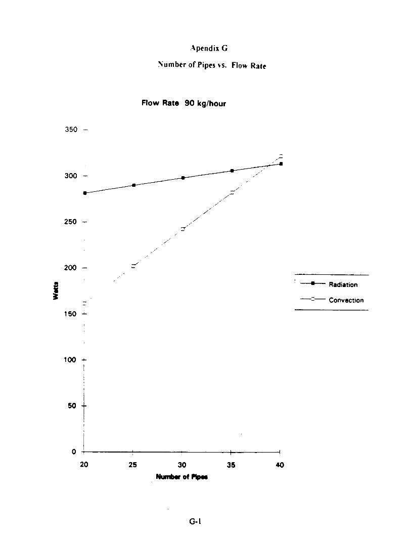
was determined using the graphs presented in Appendix G. These graphs illustrate the
difference between convection and radiation for variable flow rates. The optimum number
of pipes is 35 since this number of pipes provides the desired difference between
convection and radiation regardless of the mass flow rate.
Additional engineering decisions had to made regarding pipe diameter, the
thickness of the plate, external coating, and material choice. Length and width of the
radiative plate and their tolerances were also determined. Pipe diameter and plate
thickness were chosen simultaneously because both parameters need to be maximized for
structural purposes without exceeding the mass constraint. As a result, the plate thickness
is 0.0015 m and the pipe diameter is 0.006 m. The external coatin$ of the radiative plate
serves two purposes: maximizin 8 the outgoing radiation and minimizin 8 the incoming
infrared flux. NASA Desi_ Guide for Pressurized Gas Systems provides a list of
commonly used coatin_ and their heat transfer properties ( p. Xlll-11). From this list,
Silicone Alkyd Enamel + Titanium Oxide was chosen. The emissivity of this coating is
0.95 while the _is0.18. Thelensth and width ofthe radiative plate are
constrained by the maxinaun dimmuiom siren in tbe specification sbeet. In order to
maximize the radiafive area, the maximumailowable_ of0.813 m x 0.813 m
were used.
Appendix H ilhum'mes calculations for thermal expamion, insulation, and impact
energy. Thermal expansion calculations were made for the inside diameter of the pipes
and for the leqth and width ofthe plme. The expansion _ the pipes was found to be
less emn the muuetmm_ _ Tbe therm" expamim for tbe tmgth and width
were fca_ to be 0.447 ram, which m hi_ thaa the _ tolerance. Asa
result, considmmiom repzdins tbe_ in thermal _ between the plate and
the mounting material must be addressed. The impact force ofmicrometeoroids is given
as 89 N. This value is well under the _ allowed impact enm2y for aluminum
which is 3300 N. From the insulation cakulations, it can be concluded that a layer of
insulation as thin as 2 cm. will prevent heat losses back into the system.
2_

Table 3. Iteration Step 2
Iteration procedure (iteration number 2)
J
k I282=WMetabolic Rate ' Li i
Human Surface Area l 2.2:m'2Heat Flux _ 128.2!W/re'2 lLCVG diameter t 0.004' m i
LCVG lengthi _ ' !i 1.85m i294 KLCVG inlet temp.
Pipe length , I)
Nueselt numberi
Pipe diameter
Flow Rata
kQ/hour85
I
0.813!m
295.2413
4,36,
0.006
i !
i
EffectiveLCVG Tout Plate W'_. # Pipes Inter. Area q cony. q rad.
K m m'2 W W0.967115 30 0.459741 256.49 298.41
90 295.16801 0.967115 30 0.459741 242.24 298.3495 295.10244 0.967115 30 0.459741 229.49 298.28
100 295.04343 0,967115 30 0.459741 218.01 298.22105 294.99003 0.967115
0.9928008295.2413
3O
35353535
0.459741
0.5363640.5363640.5363640.536364
8590 295.16801 0.992800898 295.10244 0.9928008
100 298.04343 0.9928008
207.63
299.23282.61267.74254.35
298.16
306.62306.56306.51306.45
106 294.99003 0.9928008 38 0.536384 242.24 306.4
85 295.2413 1.0184867 40; 341.98 314.751.01 648871.01 64867
0.6129880.6129880.6129880.8129880.612988
295.168019O95
100105
295.10244295.04343
4O4O
322.98308.98290.69!
276.844O40294.99003
1.01848671.01 64867
i
314.7314.65314.61314.58

Aluminum, Beryllium, Magnesium, and Titanium were examined to determined the
best choice for the plate. A binary matrix in Appendix I was used to establish weights
given to different properties of the materials. A decision matrix was then used to
determine which metal had the optimal properties as seen in Table 4. A similar procedure
was used to determine the best fluid for the system. The binary matrix is presented in
Appendix J and the decision matrix is shown h_ Table 5
Figure 9 incorporates all of the previously discussed parameters and shows the
final dimensions and tolerances for the heat rejection unit. The parts, materials, and
respective quantities are presented in Table 6.
How the Embodied Design Sathfles the Specified Functions
Because the specified functions are critical to the operation of the heat rejecting
unit, the system must accommodate these functions in the design. The specified functions
are: transfer fluid, control fluid flow, transfer heat, absorb heat, and protect the system
from impacts and leaks.
The cooling fluid circulates through the pump and valve system after the fluid has
absorbed the heat from the astronaut's body. Once the fluid exits the pump and valve
system, the fluid is directed through the thirty five pipes in the radiative plate. The pipes
transfer the fluid through the radiative plate so that heat may be absorbed into the plate
and rejected into space.
Using a system composed of themggonplea, pressure 8aSe_ a positive
disp_ pump, and | _'vo valve, the nma flow rate through the radiative plate can
be controlled. Dependin$ on the t_ of the fluid and the atmosphere inside the
EMU, the hum flow rate can be varied to control the =noent of heat that canbe rejected
from the _f_eat A variable mass flow rate accounts for the chansin8 metabolic rates of
the astronaut. As the hum flow me is increa,_ the heat rejection capacity of the system
increu_.
After the _ fluid takm the exces heat from the a,mona_s body, the fluid is
tothehe= rdection=it throushthethu yfivepipesintherUi veplate. As the fluid flows tlmm_ throe pipm, the hegt is _ from the fluid into the
plate. The conductivity of the almuinum plate Mlowl the heat removed from the fluid to
be transported to the outer surface, and the heat is radiated from the plate into the space
environ. As a result, heat is tramferred from the astronauts body through the system
to the environment by the radiative plate.
Since the radiative plate is made ofalumimmt, the plate has storase ability and can
still absorb heat durin8 metabolic peaks. Energy storase durin8 metabolic peaks arises
23

Conducti_llv
20%
Bers.llium
Magnesium
Timmum
Specdic Heat DensiD Corrosiveness Safety.13% 15% 20% 25%
7<ot/ 05
Mechamcal
Ptopemcs7%
Total
8.4
7.7
5.6
4.6
Table 4. Decision Matrix for the Material
aml_ 45%vis:_m
12.5%
12.5%
Teud
TaMe 5. Decision Matrix For Fluids

nl
Item
PlateFluid
Additioaal Parts Needed forSubs_lems
ThermocoupleServo Valve
PostUve Dispiacemem Pump
Material / Specifics
Aluminum 1!00Demineraliz_ Water
Moog Vah'e,..Compal_Mass Flow Rate 25 - 150 kg/hourPressure- t00. 250 k_
Banes. Silver - Zinc42 Watts
Seal
Motor 30 Watt, ! 15 vAc, 1.4 A
Porponional Coatptler (PPC)
Quantity
!!
(Cole-_/.nstzument Company, p. 832)(SchmLdt)
Table 6 : hm List

3.00mr.
1.50 mm
/ , .
f
D = 6.00 mm
R = 1.57 mm R = 1.57 mm
Fillets and Rounds 1.57 mm
Maufacturing tolerances 0.00 +. 15 mmDrawing Not to Scale
Total Pipes 35
I I 1 i fL_ I
14.00 ,!--
, )
i (//"
t \, "\,
I .
' (I1I
,,(), )'llII
; f \i
813.00 mm
---r---
.=
f_
g_
r
..4s.._
Figure 9. Dimensioned Drawing for the Radiative Plate

from the combination of a temperature increase of the plate and the specific heat of
aluminum.
Advantages and Disadvantages of the Radiative Plate
The radiative plate has advantages over the current heat rejection system. Since
the radiative plate has a thickness of 9 millimeters, the radiative plate only consumes five
percent of the entire volume of the PLSS. Since the volume of the PLSS will be less than
the maximum volume given in the specification list, the mass of the heat rejection system
will be minimized. If the mass is minimized, the weight of the plate in the presence of
gravity may be small enough to enable the system to be used in future planetary missions.
The pumping system of the radiative plate can produce variable mass flow rates to handle
metabolic rate changes. By varying the mass flow rate, the amount of heat rejected from
the system can be controlled. As a result, the atmosphere inside the suit can be maintained
between the comfortable levels of 294 K and 300 K. Because the radiative plate is not a
fiat surface, the surface area is increased by about twenty percent from .813 to .95
meters. Therefore, more heat can be radiated while the size constraints of the radiative
plate are met. The radiative plate has only a few ¢omponeas. As a result, production
costs are kept low because there are I_ parts to _. In addition, the plate is
subject to less wear because only a few components are subjected to the environment. For
the same reason, maintenance is lowert_ and reliability of the system is increased. The
calculations for the time con.stint of tim system is pretem_ in Appcadix K. The time
const_t ofthe _ was caiculm_ to tm 0.g$4 azzottdt Thi_ number meam tim the
system will acco_ rapidly to ¢haagm in the metabolic me.
The radiative plate system also pcmmts some disadvan_q_. Became the plate is
on the outside ofthe PISS rmher than emlosed, the sy_em is subjected to hazards of the
space mvimmnem such as micrometemoids. Althoush the plate has been made to
withstand the impact of micrommeoroids up to 89 N, Itrger impacts could damage the
system. Since the radimive plate mua be coated to reflect cosmic radiation and prevent
exceuive solar hernias, mdiaxionfrom the plate is sli#uly hindered.
Design Recommendations
Msautacturin;
The recommended _ process for the radiative plate is stamping.
Stamping is a process which uses a sheet of specified material known as the stock and
slmpes'_ sheet by cutting, formi_ and bending. A die with the predetermined geometry
27

of the desired shape is pressed against the stock so that the die geometry is mirrored on
the sheet metal. Stamping is a cold working process since it is done at temperatures
below the melting point of the stock material Stamping is commonly used to make
radiators such as those found in cars. If the stock material has a large difference between
the tensile strength and the yield strength, forming characteristics are good (Trucks,
p. 150). The tensile strength and yield strength of aluminum are 83 MPa and 31 MPa,
respectively which give,, a wide range of' 52 MPa for stamping processes. Tolerances for
stamping processes are between 10 and 15 percent of the stock thickness. Fillet radii and
rounds are also functions of the stock thickness. For stock thickness of0.O015 m, the
minimum bending radius is 0.00078 m and the minimum round radius is 0.00157 m.
For the radiative plate, stamping will be done in three stages: stamping the first
side, stamping the second side, and spot welding the two pieces together. The two sides
of the plate will be joined by spot welding at one inch intervals between the pipes. Spot
welding allows for the joining of the two sheets without adding another material into the
system which contributes to the weight and increases potential safety hazards.
Cost Analysis
A cost analysis for the production ofthe radiative plate was conducted. The
analysis does not include any investment costs such as engineering hours or numagement
costs since those investments have already been made at this point in the design stage.
The cost for the radiative plate is based on the cost of the material stock, the energy cost
of bending and rotting the metal, and the cost of spot welding the two plates together.
The resulting cost of the plate is $28.80 per plate. This cost does not include the cost of
designing and prodm:ia8 the die to form the sheet metal. The cost of producing a die
ranges between $20,000 tad $50,000.
Areas for lgurtiter Stmly
The mbsystetm that lee dependent on the heat _n system should be studied
to ensure proper oameetiom. 8eoumri_ and interaaiom of the entire system. After the
water leaves the pump, the fluid needsto be separated equally to flow through the 35
pipes. One metlmd to split the flow is a plenum _. A back up power system is
needed in case the _ system fails. The back up system should allow enough time for
the astronaut W safety return to the Shuttle bay before a dangemm temperature is
reached. A warning si_ should be provided to warn the astromaR that the system has
failed. The signal that the system is malfunctioning can be reliant on p_ changes that
might indicate a leak in the system and on the t_ of the fluid that indicates iftbe
28

astronaut is bein 8 properly cooled. The manner in which the plate is attached to the PLSS
must be considered. By virtue of our design, there are two fiat plates extending from the
outer tubes. Two runners with bolts can be attached to the PLSS as seen in Figure I0.
The spacing of the bolts must be determined and the number of bolts must be determined.
Seals will be used on the system and its connection to the PLSS in order to prevent leaks.
Since most seals are made of elastomers, creep and thermal expansion will be problems in
determining what type of seal can be used. To determine the type of seals, _nher
research will be required. More information on an insulator pad that will prevent heat
from radiating back into the EMU should be obtained.
Conclusions and Future Work
Current systems used to regulate the temperature inside the EMU suit are mass
consuming and require regeneration. Mass loss constrains the time of EVA's because
mass must be resupplied. A closed system which does not require any recharging or
resupplying of material is desired. The radiative plate embodied in this paper is a closed
system since the cooling fluid is conserved throughout the system. As a result, the
radiative plate does not require a regenerated process which increases maintenance time
between EVA. In addition, the duration of EVA's can be extended because the sy_em is
not constrained by loss of mass. The radiative plate must release the heat energy absorbed
from the astronaut's metabolic emissions at a rate suitable to control the temperature
inside the EMU suit. By hncxeasin8 thin,ration of EVA possible for the astronaut, the
system will be applicable in the consuuction oftbe space station and in future planetary
mimons.
Before the final blue prim of the radiative plate and its _Jyltema can be made,
all design teams must meet to coordinate the subay_ema with the radiative plate.
Allowances for proper interfaces between subsystems such u the pump and the valve
m bedmp .The nmX step in the development of the radiative plate will be comnmnkam'on with
the uutmSgtugw regatdi_ building of a Wototype. Mte¢ the manufactt¢_ evaluates tbe
design from a production perspective, the design will likely need adjustments before it can
be _ed. Once the tirol changer have been made, the prototype can be b_u'lt and
tested.
In the future, the design wig have to be adapted for planetary misaionz.
Modificatiom may include the addition of fins to aid in convective heat tran_er in an
environment with an atmosphere. In addition, since gravitational forces may be present,
29

the mass of the system will have to be reduced so that the astronaut will not be burdened
by the weight of heat rejection unit.
two r_ls on drier of tim _ si_ _run _ to the flow
3O

References
Barr?', Roger, and Richard Chorley, Atmosphere, Weather cmd Climate, (London
Methuen & Co., 1982), p. 372
Bourell,D.,and R. Crawford, Universityof Texas atAustinME 366J Design Project
Professors (Austin, TX: 4 April 1994), memo to Engineering Staff, Classification
ME366J.
Cole-Parmer InstrumentCompany, Catalog,(Chicago,Illinois:1991),p.832.
De.sign Cnade for Pressurized Gas Systems, NASA Contract NAS7-388, Volume !,
(Chicago, Illinois, March 1966), p. XIII-I 1.
Incropera, Frank, and David De Win, Fundamentals of Heat cnutMass Trcmsfer, 3rd ed.
(New York, NY:John Wiley & Sons, 1990).
NorreU, left,NASA LiaisonatThe Universityof Texas at Austin,(Austin,"IX:15 April
1994),personalinterview.
Purser, Paul E., Maxinm A Faget, and Nommn F. Smith, Macmed Spacecraft:
Engineering Design and _on, (New York: Fairchild Publications, Inc.,
1964),p. 145.
Schmidt, Dr. Phillip,Universityof Texas (Austin,'IX:19 April1994),personalinterview.
System Descrfpt#on and Des#gn Data. EVA. NSTS 07700, Volume XIV, Appendix 7,
l_,v. J, 29_ 1988).
Trucks,H. E.,Dcs#gnO_for Econom/ca//b'cxikct/on,(Deerbom, MI: 1987), p. 150.
Vliet,Dr.Gary,UniversityofTeus(Austin,TX:7April1994),Ixrsonalinta'view.
Vogt, Greg, "Primary lifesupport system,",._su#t GuMebcx_, [mmphlet (NASA
Headquarters: EducationalAffairsDivision,1990).

Woodson, Westey E., Human Factors Design Handbook, (New York: McGraw-Hill,
1951), p. 707.
32

_ppendlx .%Specification Sheet
NASA/USRAME366J
Changes D/WI
For:
Requirements
Specification
Closed Unit Heat Rejection System
Page:Iof2
!
Rspnsbl Verify
¢
D
D
D
D
D
D
D
D
W
D
D
D
D
W
I.Function
_ovide-asuitableheatrejection.
Maintain temperature during all levels of metabolic activity.
Provide monitored use for 6 hrs. duration.
Rejectheatto spaceenvironmentduringbothday and nighttimeactivities.
2._admr,_xTotal surface area of Im^2 (10.8ft^2).
Portable Life Support System (PLSS) not to exceed 81.3 cm x81.3 cmx 17.8 cm (32" x 23" x 7") (for connection to SpaceSuit Assembly (SSA)).
3. ForcesWithstand launch loads up to 3g.
Withstand direct it_pact of 89 N (20 lbs)
Minimize mass: Upper bound of 11.4 kg (25 lbs)
,
°mg requurementg250 W average rnembolk: rote for 6 hours1500 W-he _ metabolic heat rejectionPeak mcmbofic mw of 600 W for 6 minutesPeak metabolic mm of 400 W i'm'36 minutes(See Filpn'e: lVleabolic Rate PmfiM)
s. Mam_Working fluid must be non-toxic, nonflanmmbl¢, andmma-comadvL
Sylmn immsum kom 100 to 250 kPa (14.$ m 36.3 psi).
mam flow mtc flora 25 to ISO _ (1.7 to 10.3
6.physics/input of utrmmut to the heat rejection
sysmn (numba' of stq_sm"cxpendod cm=ly).
(BoureU)
A-I

NASA/USRAME366J
_hanges D/W"
_or:
Requirements
Specification
Closed Unit Heat Rejection SystemPage: 2 of 2
Rspnsbl Verify
D
D
D
D
D
D
D
D
W
W
Fail-safe toof thesystem maintain space suit environment if part (orall) heat rejection system fails.
No sharp exposed surfaces, edges, or comers.
Apply overall safety factor of 1.5 for heat rejection system.
8.
75.7 to 453.9 W/mA2 (24 to 144 Btu/hr ft^2) for solarradiation.
52.6 to 268.6 W/n'_2 (16.7 to 85.2 Btu/ba"ft"2) for infraredradiation.
(See Table 1: Station Suit Hut Leaks)
Operate in zero (micro) gravity environment
No mass transfer out of the cooling system.
Operate in zero pressureenvironment.
9. Produea_Number o4"unils:
Development- !Flight - LessthanI$
Total prototype cost less than I m/lllon dollars.
Lifetime of unit:One yur on orbit.52 EVA's atIEVA perweek befocegroundma/n_nance.15 yeartoudlifetime.
%
A-2

Appendix B
Mass of Packed-Bed of Ice Spheres
Metabolic Rate
Latent Heat
Total energy out
Mass
Mass constraint
282 Watts
330000 Jouls/kg
6091200 Jouls
18.45818 kg
11.2 kg
The minimum mass for the ice heat sink is 64_over the mass
constraint established by NASA
B-I

Appendix C
Binary Matrix for Concept Variants
Catcgo_ Capac_" to Time Mass No. of Total
Absorb Heat Constant Components
Cal_c_v,. to X i [ 1 3.M:)sorb Heat
Time Constant 0 X 1 I 2
Mass 0 I X 0 I
No of 0 0 1 X 1
Components
C-I

Appendix D
Reynolds Number Calculation
The Reynolds number has to be calculated in order to determine if the flow inside
the pipe is turbulent or laminar. The transition point between laminar and turbulent flow is
2300. Using the highest mass flow rate will result in the highest Reynolds number. If
such number is under 2300, the flow can be assumed to be laminar.
Assumptions: - mass flow rate (Q) = 150 kg/hour
- number of pipes (N) = 35
- pipe diameter (d) = 0.005 nun
- kinematic viscosity (_,) = 1.007 E -07 (mZ/sec)
_ml s) =0
A. 3(KI0.1000 • N
This results in a velocity of 0.10 m/see.
VdRe--m
Is
The resulting Reynolds number is 400, which indicated that the flow can be considered
laminar.
D-I

_o_§ §o oo __;_0 0 0 00000o00o o 0o0000 o
_ ®®.. __o. _.
00000000
!iii° i°!iiiiE ' "000 o0 00000000
<
Z
o_
¢Jlal
z0(J

Appendix F
Internal Pressure Calculations
r {int)(m)
0.0030.003
0.00150.0015
0.0030.003
0.00150.0015
0.003
0.0030.00150.0015
thick.(m}
0.00150.002
0.00150.002
0.00150.002
0.00150.002
0.0015
0.0020.0015
0.002
pressure Max. Shear MaterialKPa Stress (KPa)
250250250250250250250250250250250250
Yield
Strength
125 Aluminum 2000093.75 Aluminum 20000
62.5 Aluminum 2000046.875 Aluminum 20000
125 Mag. Alloy 8000093.75 Mag. Alloy 80000
62.5 Mag. Alloy 8000046.875 Mag. Alloy 80000
125 Titanium 40000093.75 Titanium 400000
62.5 Titanium 40000046.875 Titanium 400000
AllowableShear
6666.667
6666.6676666.6676666.66726666.6726666.6726666.6726666.67133333.3133333.3133333.3133333.3
Matedal
Material
Aluminum
BerylliumMagnesium
Density YieldStrengthKPs
2700 200001850 NIA1740 80000
(all S.I. units)
Conduct. Cp
23720O156
90318251024
F-!
Apendix G
Number of Pipes vs. Flow Rate
Flow Rate 90 kg/hour
350 -
250
200 --
J
/
/
J
//
i
•J
J
150 _-
= Radiation
'-- Convection
IO0
50
0
-4-
r
i
I
i
tr
ItP
20 25
i
30
Ntanll_ of
I
35
I
4O
(3-1

Flow Rate 95 kg/hour
350 -
t
300 -
250 -
200 -- j_
_J
J
JI
J
J
./
J
J/"
1
/J
.J/
fj_
150
;
100 -
i
I
50
0
20
I
25 35
I
4O
G-2

Flow Rate 100 kg/hour
350 -
ii:
300 -J
J
250 -
200 --
l
150 -,-i
J
/i'
•/
w
J/
/
J
J
./
: Radiation
.2. Convection
100 --
iI
5o +I
!
i0 i
2O
i i I, I
25 30 35 40
Nm of ml_
G-3

Flow Rate 105 kg/hour
350 -
t
300
250 --
200 --
150 _-
"r
/
P
/
J/
f-J
J
J/
J
/L-.
.J/"
J
100 -
It
I
50 _-
-" Radiation
_- Convection
0
2O
i t I I
25 30
Number of
35 _0
('..4
Appendix H
Additional Calculations
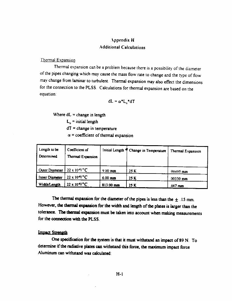
Thermal Expansion
Thermal expansion can be a problem because there is a possibility of the diameter
of the pipes changing which may cause the mass flow rate to change and the type of flow
may change from laminar to turbulent. Thermal expansion may also effect the dimensions
for the connection to the PLSS. Calculations for thermal expansion are based on the
equation:
dL = a*Lo*dT
Where dL = change in length
Lo = initial length
dT = change in temperature
a = coefficient of thermal expansion
Length to be
Determined
Coefficient of
Thermal Expansion
Initial Length d Change in Temperature Thermal Expansion
Outer Diameter 22 x I0"6/°C 9.00 mm 25 K .00495 nun
Inner Diameter 22 x 10"6/°C 6.00 mm 25 K .00330 mm
813.00 mum22 x I04/oc 2_ KWidth/Lehigh .447 mm
The thermal expansion for the diameter of the pipes is less than the +. 15 nun.
However, the thermal expansion for the width and length of the plates is larger than the
tolerance. The thermal expansion must be taken into account when making measurements
for the cormcction with the PLSS.
One specification for the system is that it must withstand an impact of 89 N. To
determine if the radiative plates can withstand this force, the maximum impact force
Aluminum can withstandwas calculated:
H-I

Impact Strength x Time in Contact/Length
The length of the impact is estimated to be the diameter ofa micrometehod, 01ram The
contact time is estimated to be .001 sec. The impact strength for Aluminum is 330 J/sec.
These values give an impact force of 3300 N, this is much greater than the 89 N specified,
therefore the radiative plates can withstand the impact.
Insulation
The purpose of insulating the inner wall of the heat rejection system is to keep heat
from going back to the astronaut. In the calculations, glass fiber insulation is used. The
thermal conductivity of this material is 0.043 W/InK. Glass fiber is used since this material
will not outgas in space. In order to decide on a thickness for the insulation, the heat
transferred across the insulation layer has to be minimized. The heat transfer through the
insulation can be calculated with the following expression:
k_m
q LA'(Tow-T.,)
k = 0.043 W/InK
L ffi0.813 m
A = 0.78 m^2
Tout ffi300 K
T in = 285 K
Thickness Heat Transferred
0.005 m 27.95 Watts
0.01 m 13.97 WaRs
0.02 m 6.98 Watts
Ifan insulationof 2 cm. isused,only 7 Watts are tranfferredback to the astronaut.This
value is approximately 2% of the heat radiated out of the system.
H-2

,Appendix I
Binary Matrix for the Material
Catego_
Conducuvi_
Specific Heat
Conducusaty.
X
0 X
[:)ensi_ 0 0Corrosiveness 1 1
I 1Safe_"Mechamcal
Properties
Specific Heat DensltT,. Corrosweness Safe_'
1 0 0
1 0 0
X ! 0
0 X 0
I I X
1 0 0
Mcchamca
Propcrt_cs
1
1
0
l
!
X
Total
3
2
I
$
5
1
bl

Appendix J
Binary Matrix for Fluid Considerations
Catcgo_ Rcactl_ eness
and CorrosionSafe_
Reactiveness X 1 1
and Corrosion
0 X 1
0Safcn'
Viscosi_,Coefficient of
Thermal
Expansion
Viscosi_
X
Cocfficlcnt of
Thermal
E.,q_ansion0
0
0
X
Total
2
I
I
3
J-I

Appendix K
Time Constant Analysis for the Radiative Plate
To obtain the time response of the radiative plate, bond
graph techniques are used to model the heat exchanger system and
to determine the time constant of the system. In this analysis,
the LCVG is assumed to be 100% efficient. All of the bond graph
elements are assumed to be ideal and linear. The following is the
bond graph of the heat exchanger system:
El
° °'-0 E
C.2o a. c. 6.
For this thermal system, the constitutive relations are:
Q,_.o"c,,_o e,_ - R.Q,
- c.e %,,. R...fl.,
The junction equations are glvenby:
O, =O,,, + 8
O =e.+en
From the above bond graph and the Junction and constitutive
relations, the following state equations are derived for this
second order system:
K-I
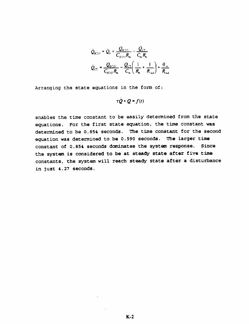
Q._.,, = Qs ÷ Q.:,, _ Qc-:,.c,,:o c.&
OHio _O,.../_L + 1 ]÷ 0.
Arranging the state equations in the form of:
rQ + Q " f(t)
enables the time constant to be easily determined from the state
equations. For the first state equation, the time constant was
determined to be 0.854 seconds. The time constant for the second
equation was determined to be 0.590 seconds. The larger time
constant of 0.854 seconds dominates the system response. Since
the system is considered to be at steady state after five time
constants, the system will reach steady state after a disturbance
in just 4.27 seconds.
K-2


![Embodiment Design Process in the Development of Articular ... · the embodiment design phase in order to organize all the principles and the embodiment inputs and outputs [11], [12].](https://static.fdocuments.net/doc/165x107/5e70a71530075f00063c338b/embodiment-design-process-in-the-development-of-articular-the-embodiment-design.jpg)