The effect of the rare earth elements on the hot ...
146
Scholars' Mine Scholars' Mine Masters Theses Student Theses and Dissertations 1960 The effect of the rare earth elements on the hot workability of The effect of the rare earth elements on the hot workability of ingot iron ingot iron L. A. Neumeier Follow this and additional works at: https://scholarsmine.mst.edu/masters_theses Part of the Metallurgy Commons Department: Department: Recommended Citation Recommended Citation Neumeier, L. A., "The effect of the rare earth elements on the hot workability of ingot iron" (1960). Masters Theses. 5565. https://scholarsmine.mst.edu/masters_theses/5565 This thesis is brought to you by Scholars' Mine, a service of the Missouri S&T Library and Learning Resources. This work is protected by U. S. Copyright Law. Unauthorized use including reproduction for redistribution requires the permission of the copyright holder. For more information, please contact [email protected].
Transcript of The effect of the rare earth elements on the hot ...

Scholars' Mine Scholars' Mine
Masters Theses Student Theses and Dissertations
1960
The effect of the rare earth elements on the hot workability of The effect of the rare earth elements on the hot workability of
ingot iron ingot iron
L. A. Neumeier
Follow this and additional works at: https://scholarsmine.mst.edu/masters_theses
Part of the Metallurgy Commons
Department: Department:
Recommended Citation Recommended Citation Neumeier, L. A., "The effect of the rare earth elements on the hot workability of ingot iron" (1960). Masters Theses. 5565. https://scholarsmine.mst.edu/masters_theses/5565
This thesis is brought to you by Scholars' Mine, a service of the Missouri S&T Library and Learning Resources. This work is protected by U. S. Copyright Law. Unauthorized use including reproduction for redistribution requires the permission of the copyright holder. For more information, please contact [email protected].

THE EFFECT OF THE RARE EARTH ELEMEN·TS ON
Tlm HOT WORKABILITY OF INGOT IRON
BY
LEANDER ANTHONY NEUMEIER
ca~------
A
THESIS
submitted to the raculty or the
SCHOOL OF MINES AND METALLURGY OF THE UNIVERSITY OF MISSOURI
in partiai rulrillment or the work required ror the
Degree or
MASTER OF SCIENCE, METALLURGY MAJOR
Rolla, Missouri_
1960
. !7( '. ~prov.ed by
~~i=t,._---~--~~~~L.-i=--<-~~-------(Advisor) __ _y_l.L,,t~-L~~~~===---
17'~ tc.JJ.. ··-=G~~~~

TABLE OF CONTENTS
LIST OF ILLUSTRATIONSo o LIST OF TABLES o o o o o
• 0
• 0
0 0
0 0
0 0 0 0 0 . 0 0 0
0 0 0 0 0 0 0 0
0 0
0 0
Page 4 7
I~
IIo
IIIo
ABSTRACT o • o ••
ACKNOWLEDGEMENTS. o
INTRODUCTION o • o
0 0 00 00 O O O O O O O O
0 0 0 0 0 0 0 0 0 0 0 0 0 0
O o . 0 0 • • • 0 0 • • 0 0 0
8
9
10
IV. · ·REVIEW OF LITERATURE • 0 0 0 0 0 0 0 0 0 0 0 0 13
13 16
V.
VI.
VIIo
VIII.
IX.
lo 2o
Early Research. o o o ••• o
Later Work • • o o o • • • • o
THE RARE EARTH ELEMENTS o • o 0 0 0
O O O O O O
0 0 0 0 0 0
0 0 0 0 0 0 28
1. Electron Configuration ••••••••• o 28 2o Occurrence, Extraction, and Separation. o 28 3o Physical and Chemical Properties o o •• o 30 4 o A pplica ti ons o • • o • • o o o o • • • • • 38
HOT SHORTNESSo • o 0 0 0 0 0 0 0 0
lo 2. 3o 4.
Effect of Sulfur. o •••
Effect of Oxygen • • • • .• Effect of Copper ••••• Effect of Aluminum. o ••
• 0
• 0
0 0
0 0
0 0 0 0 0 0
O O O O O O
• • • O O O
• • 0 0 0 0
0 0 0 0 0 0
:METHODS OF EVALUATING HOT WORKABILITYo o • 0 0
1. Hot-Bend Test •• . o o o o o •• 0 0 O O O O
2. Single-Blow, Drop-Hammer Testo 3. Hot-Twist Method •.• · o • • • . •
0 0 0 0 0 0
0 0 0 0 0 0
EXPERIMENTAL PROCEDURE • • o • 0 • 0 0 O O O O
lo Melting Technique. 0 0 O ·O O O O O O O O O
2. Sampling for Chemical Analysis .•••• o o
3o Hot Rolling and Swaging •••• · 4 .- Hot Twisting • • o o • o • • •
EXPERIMENTAL RESULTS. 0 0 0 0 0 0
lo Nominal Additions. to Heats •• 2. · Results of Hot-Twist Testo • •
0 0 0 0 0 0
0 0 O O O O
o o o o o o·
• 0 • O O O
0 0 0 O O O
42
42 45 45 48
53
53 53 54
59
59 68 69 74
·76
76 76
2

3
TABLE · OF CONTENTS Page
4o Evaluation of Resultso 0 0 0 0 0, 0 0 0 0 0 79 5o Sulfur Printing. 0 0 0 0 0 • • • 0 • 0 0 0 95 60 Study of Inclusions. 0 0 0 • • 0 . • • 0 • 0 107
x. CONCLUSIONS. 0 0 0 • 0 0 0 • 0 • 0 0 0 0 • 0 119
SUGGESTIONS FOR FURTHER STUDY. • 0 • 0 • • • 0 • 0 121
APPENDIX I 0 0 • 0 0 • • •. .. • • • • • • • • • • . . 122
APPENDIX II. • • • • • • • • • • • • • • • 0 126
APPENDIX III 0 0 • • • • • • • • • • 0 • 0 0 • 0 0 132
APPENDIX IV. 0 0 0 • • • •O • 0 0 • 0 0 • 0 • • • 0 135
APPENDIX V 0 • • 0 0 • • 0 0 0 • 0 • 0 • • • • 0 • 138
BIBLIOGRAPHY • • 0 • 0 • • • 0 • 0 0 0 • • • • • 0 141
VITA 0 0 . 0 0 • 0 0 0 • 0 • 0 • • • • 0 • • 0 • 0 145

LIST OF ILLUSTRATIONS
Figures
1.
2.
4.
5. 6.
7.
8.
9.
The iron-sulfur system. • • • • • • • • • • • • • •
The FeO-FeS system. • • • • • • • • • • • • • • • •
The iron-oxygen system. • • • • • • • • • . • • • •
The iron-copper system. • • • • • . • • • • • • • .. The iron-aluminum system. • • • • . • • • . • • • •
Hot-twist apparatus • • • • • • • • • • • • • • • •
Furnace assembly and converter unit •• • • • • • •
Ingot mold assembly •• • • • • • • • • • • • • • •
Solubility of oxygen in liquid iron ••• • • • • •
4
Page
44 ·
46
47
51
52
56
60
61
64
10. Activity of oxygen in binary liquid iron alloys. • 65
11.
12.
Two-high rolling mill ••• • • • • • •
Swaging machine and heating furnace ••
• • • • • •
• • • • • •
13. Photomicrographs for grain size:
14.
15.
15.
a). Hot rolled •••••••••••••••• b). Hot rolled, hot swaged and cold swaged •• c). Hot rolled and cold swaged ••••••••
As-cast ingot sections, machined sections, and rolled and swaged bars •••••••
• • • • • • • • •
• • •
a). Bars prior to hot twisting ••••••••••• b). Bars after hot twisting. ~-••••••••••
Number of twists to failure versus per cent rare earth metal added •••••• • • • •
16. Number of turns to failure of killed and rimmed
70
70
72 72 72
73
75 75
81
ingot irons versus temperature of twisting 82

Figures Page -
17. Per cent sulfur versus number of twists to failure 84 .
18. Per cent sulfur versus per cent rar~ &arth metal added. • • • • • • • • • • • • • • 85
19. Per cent oxygen versus number of twists to failure 88
20. Per cent.residual aluminum versus number of twists to failure • • • • • • • • • • • • 89
21. Per cent oxygen versus per cent residual aluminum. 90
22. The iron-cerium system 0 • • • • • • • • • • • • • 92
23. a). Sulfur print. Ingot No. 1, top • .As cast. • • • 96 b). Sulfur.print. Ingot No. 1, bottom. As cast 0 • 96
24. a). Sulfur print. Ingot No. 5, top·. As cast. • . • 96 b). Sulfur print. Ingot No. 5, bottom. As cast 0 • 96
25. a). Sulfur print. Ingot No. 7, top. As cast. • • • 97 b). Sulfur print. Ingot No. 7, bottom. As cast • • 97
26. a). Sulfur print. Ingot No. 9, top. As cast. • • • 97 b) 0 Sulfur print. Ingot No. 9, bottom. As cast 0 •• 97
27. a). Sulfur print. Ingot No. 11, top. As cast • • • 98 b) 0 Sulfur print. Ingot No. 11, bottom. As cast. • 98
28. a). Sulfur print. Ingot No. 12, top. As cast 0 • • . 98 b). Sulfur print. Ingot No. 12, bottom. As cast. • 98
29. a). Sulfur print. Ingot No. 13, top~ As cast • • .• 99 b). Sulfur print. Ingot No. 13, bottom. As cast. • 99
30. a). Sulfur print. Ingot No. ·14, top. As cast. • •· 99 b). Sulfur print. Ingot No. 14· bottom. As cast. . 99
. ' 31. Mac:roetdhed sections, ingot No. 1, top and bottom. ·102
32. Macroetched sections, ingot No. 11, top and bottom 102
33. Macroetched sections, ingot ·No. 13, top and bottom 102

6
Figures Page
34.
35'.
36.
37.
38.
39.
40.
41.
42. 430
44. 45.
46. 47.
48. 49.
50. 51. 5·2. 53.
54.
a). Microstructu~e, ingot No. 11, bottom, near edge ·103 b). Microstructure, ingot No. 11, bottom, center 103 c). Microstructure; ingot No. 11, top,- center. • •• 103
Sulfur print. Heat No. 1; slag-scum bead •••••• 105
Sulfur print. Heat No. 14, slag-scum bead ••
Sulfur print. Heat No. 5, slag-scum bead ••
Sulfur print. Armco iron punching •••• • •
• •
. .. 0 •
• • 105
. . . 106
• • 106
Sulfur print. Bar 1-2. Hot rolled and cold swaged •• 106-
Sulfur print. Bar 14-2. Hot rolled and cold swaged. 106
a). Microstructure, Armco iron punching. Unetched •• 109 b). Microstructure, Armco irn~ punching. Etched ••• 109
Microstructure, ingot No. 1, top. Unetched ••••• 111 Microstructure, ingot· No. 1, bottom. Unetched •••• 111
~tlcro$tructure, ingot No. 5, top. Unetched ••••• 111 Microstructure, ingot No. 5, bottom. Unetched •••• 111
Microstructure, ingot No. 9, top. Unetched • .•••• 112 Microstructure, ·1ngot no. 9, bottom. Unetched •••• 112
Microstructur·e, ingot No. 11, t ·op. Unetched ••• Microstructure, ingot No. 11, bottom. Unetched·.
'.Microstructur.e, ingot No. _13, top. Unetched •• ~ Microstructure, ingot No. 13, bottom. Unetched •
• 0
• • 112· 112
• • . 113 • • 113
Micros·truct~e, ingot No. 14, top. Unetched. . • • • • 113 Microstructure, ingot No. 14, bottom. Unetched ••• 113
a) .:.,·Micros.truc~ure, ingot No.· 1, top .• 500X, unetched 115 b). Mi~rostructure, · ingot No. 1, top. · 5oox, etched·. 115
a). Microstructure, ingot 13, top. 500X, unetched •• 116 b). Micros.tructure, ingot 13, top. 500X, etched. · •• 116
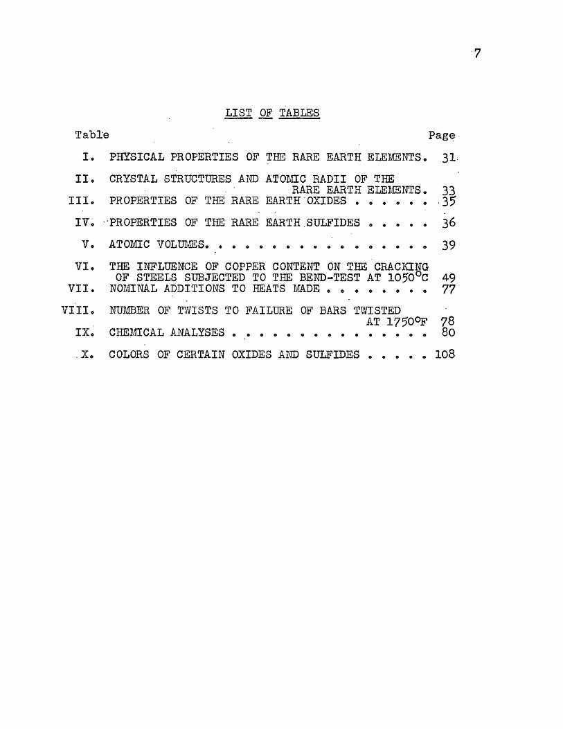
LIST OF TABLES
TabJ:e Page
I. PHYSICAL PROPERTIES OF THE RARE EARTH ELEiv.TENTS. 31.
II. CRYSTAL STRUCTURES Ai\TD ATOMIC RADII OF THE RARE EARTH ELEMENTS. 33
III. PROPERTIES OF THE RARE EARTH .OXIDES •••••• . 35
IV. ··PROPERTIES OF THE RARE EARTH .SULFIDES • • 0 0 0 36
39 V. ATOMIC VOL U:ME~S. • • • • • • • • • o o 0 • 0 0 0
VI.
VII.
VIII.
IX.
. x.
THE INFLUENCE OF COPPER CONTENT ON THE CRACKING OF STEELS SUBJECTED TO THE BEND-TEST AT 1050°c 49
NOMINAL ADDITIONS TO HEATS MADE •• o ••••• 77
NUMBER OF TWISTS TO FAILURE OF BARS TWISTED AT 1750°F 78
CHE:MICAL ANALYSES ••••••••••••••• 80
COLORS OF CERTAIN OXIDES AND SULFIDES ••••• 108

8
L_ ABSTRACT
The effect of ~ischmetal and rare earth oxides on
the hot workability of ingot iron in the ·hot-short region
was studied. Thirteen heats were melted in air in a basic
lined induction furnace. All heats were thoroughly deo~i
dized·with aluminum prior to the rare ea~th additions.
Mischmetal was added in amounts of 0.1, 0~3 and Oo5 per
cent. Rare earth oxides were added in amounts of 0.1 and
0.2 per cent. Temperatures were maintained at approximately
2900°F and holding intervals between mi'schmetal additions
and pouring at two minutes. Bars were hot rolled and swaged
for hot twlsting in the hot-short region. Sulfur distribu
tion was studied by sulfur printing and inclusions were
studied by metallographic methods.

9
lL. AC·KNOWLEDGEMENTS ..
Thanks are due to many who assisted.in various ways.
in the preparation or this worko
T"!le fo~lowing industrial concerns supplied, free or charge, the rare earth additives usedo
Rare earth·metal mixtures: American Metallurgical Products Company, Incorporat.ed,
New Castle, Pennsylvania Mallinckrodt Chemical Works, Sto Louis, Missouri
Rare earth salts: Lindsay Chemical Division, West Chicago, Illinois Davison Chemical Company, Pompton Plains~ New Jersey Metallurgical Enterprises, Buffalo, New York
The chemical analysis was performed at no cost by.
Allegheny Ludlum Steel Corporation, Brackenridge, Pennsyl
vania, and Armco Steel Corporation, Middletown, Ohioo
The Babcock and Wilcox Company, Tubular Products
Division, Milwaukee, Wisconsin performed the hot twisting
of the test bars. Special thanks are due Mr. Eo Gammeter
who spent considerable time in corresponding and in-super
vising the hot twisting of the bars.
Dr. Ao Wo Schlechten was particularly helpful in
securing materials, services, and equipment whenever needed.
Dr. w. Ao Frad gave freely of his time in.the metallography
laboratoryo Mro Ro V. Wolf assisted in the foundry. The
assistance and co-operation of other faculty members .and
graduate students is also ac.knowledged.
And last,. but by no means least, thanks are due to
Dr. Do So Eppelsheimer who suggested,the project, acted as
advisor, and contributed many helpful suggestions through
out the work.

IIIo INTRODUCTION
The improvemen~ of the physical and.mechanical pro
perties of metals and a:Lloys has always been of prime impor
tance to the metallurgisto These des·ired properties have
often been instilled in metals by relatively small quanti
ties of alloying elements. The rare earth e·lements have .in
recent years come to the forefront as such alloying ele
ments in steelmakingo ·
The true significance of the rare earths as alloying
elements in steelmaking has been realized .only since 19500
Among the benefits reported derived from their use in steels
are improved hot workability and in a number of instances
significan~ desulfurization. A literature survey revealed no
report of the rare earths having been investigated as alloy
ing additions to ingot iron.
Ingot iron is produced in.the open hearth much the
same as steel. bue to the greater purity reguirements of
the iron, however, the temperature must be appreciably
higher toward the end of the refining process. The extent
of oxidation is therefore much greater than in steel pr·o
duction and the resulting iron is quite high in iron oxideo
The oxygen content may run as high as 0.10 per cento Armco
Steel Corporation lists a typical analysis of their ingot
iron as: c Mn p s Si Fe
0.015 per ce.nt 0.028 0.005 00025 0.003 balance
10

11
The maximum values of the impurity contents it:i per cent are:
0.010 P; 0.030 s; 0.15 Cu; and 0.10 total of c, Mn, P, S
and Si.
Ingot iron is inherently hot short in the temperature
range from 1600 to 1950°F (870-1065°c). Hot shortness is
most frequently attributed t~ impurities of sulfur, oxygen
and copper. Aluminum has been reported to contribute to hot
shortness. In the absence of sufficient manganese, sulfur
contents in excess of 0.010 per cent cause hot shortness.
Due to corrosion, electrical and magnetic _specifications,
ingot iron does not contain sufficient manganese to eff~c
tively tie ~p the sulfur in a harmless form. Susceptibility
to -corrosion, electrical resistivity, and hysteresis loss
all increase with increasing manganese content. High oxygen
contents are always present in ingot iron as a result of the
method of manufacture. Copper contents in excess of approxi
mately 0.10 per cent lead to a hot-short condition in low
carbon steel. Copper contents of iron and steel have been
increasing .annually due to copper in recycled scr~p me~al.
Copper is not removed in iron and s~eel refining. Alumf-num
is used to deoxidize ingot iron in the la.dle .and small per
centages of aluminum are always present in the finished
iron.
Under favorable conditions, the rare earth elements
are both strong deoxidizers and desulfurizers in steel.
Their effect on copper in steel has not been investigated.
Rare earth oxides have been repor_ted to oxidize aluminum

in aluminum-killed steels.
This investigation was undertaken to. study the
effects of the rare earths as additives to ingot iron. The
rare earths in metallic form and as oxide mixtur·es were
used in the investigation--both separately and in combina-. .
tion. The primary objective of the research has been to
12
study the effects of the rare earths on the hot . workability
of ingot iron in the hot-short region.

13
. lli REVIEW OF LITERATURE
Considerable research has been :perf~rmed, particular-
ly. during the last ~eri y~ars, concerning the use of the rare
earth elements as additiv~s in· steel with the aim of
instilling more desirable. properties. The results reported
have-often been contradictor·y and inconclusive _. In the lit
erature review which :follows·; quantitative ~~ta have been
included only when a specific investigation h~s been con
cerned with desulfurization.and hot·workability. The sum
maries are of necessity brief, and some i~vestigations have
been omitted to avoid unnecessary .repetition of ·similar
results.
1~ Early Research
The early research goes back to the post World War I
period. Although the true significance of the.rare earths as
alloying elements in steel was not realized until. 1950, this
early work was, nonetheless, of importance in_laying _the·
foundation for the later work. ( 1) .
In 1917 Vogel . determined the cerium and :Lrcm .·phase
diagram. Cerium was _reported to be $Oluble in alpha-iron to
a maximum of approximately 12 weight per ·cent., and in gamma
iron to approximately 15 weight per cento An eutectic .was· ·
found to , occur at abou~ 4o 5 weight :per cent irono The ·system
was studied by metallographic methodso ·. (2)
Allison and Rock ·in 1920 added 11 cela" (cerium-
lanthanum alloy) in amounts of OolO and 0.15 per cent to
four heats of a carbon steel. Ther found no significant

14
change in yield point, tensile strength, elo~gation and
reduction in area. They concluded that the · "cela" conf.errea
no evident benefit. (3)
In 1922 B_urgess and Woodward at the Bureau of Stan-
dards reported the results of an extensive study of ten
* carbon steel heats to which.yarious amounts of cerium ·had
been added. They found that with about Oo25 per cent cerium,
the tensile properties were increased with an accompanying
loss in ductility. With cerium contents of more than 0.30
per cent, a heavy segregation occurred. Tpey mentioned that
cerium was thought to be a desulfurizer but presented no
data on sulfur contents. . (4)
Spring in 1922 reported the results of adding a
mixed metal containing 50 per cent cerium, 25 per cent
lanthanum, and the balance other rare earths to f'our heats
of converter cast steel. The sulfur contents before and
after the cerium_alloy additions are tabulated below:
S~lfur Sulfur before after
Cerium Alloy Cerium Alloy Cerium Alloy Converter Added Add-i tions Additions ~low No. {Per Centl (Per ·centl !Per Centl
1565 0.5 0.086 0.043 1598 1.0 0.088 00036 1643 loO 00081 00027 1823 · loO · 0.084 0.041
In contrast to the findings_ of Burgess and· Woodward, 1121.§..,
Spring :round that the steel was much cleaner·, displayed no
ingotism, and was more ductile as a.result of the rare earth-
Mischmetal· was often re£erred to as simply cerium during_'' this period.
15
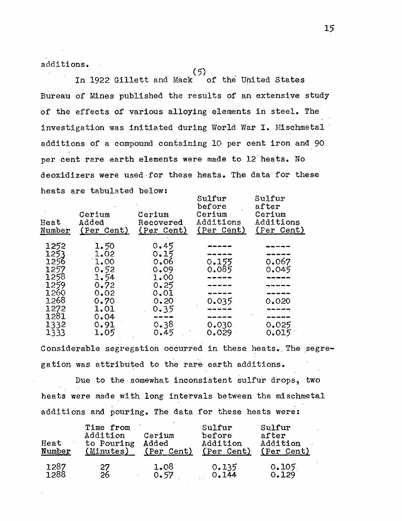
additions. ( ~j')
In 1922 Gillett and Mack of the United States
Bureau of Mines published the results of a~ extensive study
of the effects of various alloying elements in steel. The
investigation was initiated during World War I. Mischmetal ·
additions of a compound cont.aining 10 per cent iron and 90
per cent rare earth elements were made to 12 .heats. No
deoxidizers were used-for these heats. The data for these
heats are tabulated below: Sulfur Sulfur before after
Cerium Cerium Cerium· Cerium Heat Added Recovered Additions Additions Number !Per Cent) !Per Cent} {Per Centl !Per Centl
.1252 1.50 0.45 ----- __ ..... __ 125~ 1.02 0.15 ------ ------125 ·1.00 0.06 0.155 0.067 1257 0.52 0.09 0.085 0.045 1258 1 •. 54 1.00 ----- -----1259 0.72 0.25
_,.... ___ -----1260 0.02 0.01 ----- -----1268 0.70 0.20 0.035 0.020 1272 1.01 0.35
____ _,_ ------1281 0.04 ------ -----1332 0.91 0.38 0.030 0.025 1333 1.05 0.45 0.029 · 0.015 .
Considerable segregation occurred in these ~eats •. The· .segre
gation was attributed to the rare earth additions.
Due·to the somewhat inconsistent sulfur drops, two
heats were made _with long intervals between the mischmetal
additions and pouring. The data.for these heats were:
Time from Sulfur Sulfur Addition Cerium before · after
He.at to Pouring Added Addition Addition Number {Minutes)' ~Per Cent} {Per Cent) tPer Cent)
1287 ·27 1.08 0.135 .· 0.105. 1288 26 0.57 0.144 0.129
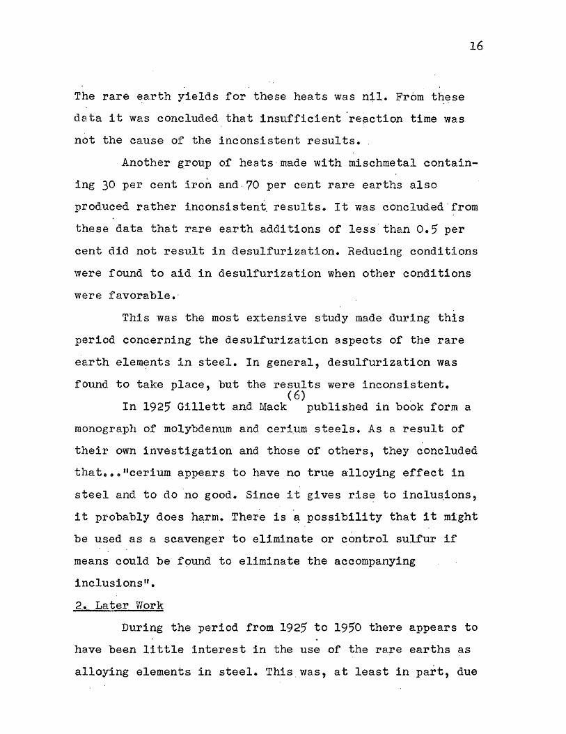
The rare earth yields for these heats was nil. From these
data it was concluded that insufficient 're~ction time was
not the cause of the inconsistent results • .
16
Another group of heats·made with mischmetal contain
ing 30 per cent iron and -70 per cent rare earths also
produced rather inconsistent. results. It was concluded · from
these data that rare earth additions of less.than 0.5 per
cent did not result in desulfurization. Reducing conditions
were found to aid in desulfurization when other conditions
were favorable.·
This was the most extensive study made during this
period concerning the desulfurization aspects of the rare
earth elements in steel. In general, desulfurization was
found to take place, but the results were inconsistent. ( 6)
In 1925 Gillett and Mack published in book form a
monograph of molybdenum and ceri.um steels. As a result of
their own investigation and those of others, they concluded
that ••• 11cerium appears to have no true alloying effect in
steel and to do no good. Since it gives rise to inclus.ions, . .
it probably does harm. There is a possibility that it might
be used as a scavenger to eliminate or control sulfur if
means could be f9und to eliminate the accompanying
inclusions".
2. Later Vlork
During the period from 1925 to 1950 there appears to
have been little interest in the use of the rare earths as
alloying elements in steel. This.was, at least in part, due

17
to the unfavorable report of Gillett and Mack, ibid., page
226.
It was not unt11 ·1950 that widespread interest in
the rare earths as ad.ditives to steel we.s again revived. (7)
Post, Schoffstall, and Beaver in 1951 reported on an ex-
tensive stud.y of the effect .on hot workability of ceriu~ and
lanthanum additions to stainless steel. They round that the
rare earth additions improved the hot workability of
austenitic stainless steels with nickel contents ranging
from four to 70· per cent a.nd 10 to 60 per . cent of elements
from the group of chromium, molybdenum and tungsten. It was
fou.nd that .the amount of any one element in the latter
group must .not exceed 30 per cent. The amount of rare earths
required to obtain improved hot workability was determined
by the nickel content. Cerium and lanthanum additions from
0.02 to 0.04 per cent were effective in promoting better hot
workability in high frequency and basic electric arc melted
alldys such as types 308, 310, 316 and others. Additions of
cerium and·lanthanum in the range of 0.08 to 0.18. per .cent
impro~ed hot workability in nicke~-chromium-molybdenum~
copper and other high-alloy stainless steels-developed for
high temperature strength and corrosion resistance. (8)
In 1951 Berry and Dorvell studied the ~ffect of
using mischmet~l (50-55 per cent Ce, 22-25 per cent La) as
a supplementary addition to steel. They reported that the
additions eliminated the low ductility and low impact
strength or dead-killed steel when only aluminum was used

18
as the deoxidizer. They attributed the improv~d propert_ies
to random distribution of the globular, higher-melting, rare.
earth sulfide inclusions· in contrast to the. lower-melting
eutectic sulfide inclusions which form intergranular films
when e.luminum alone is used as the deoxidizer. The misch-
metal additions were in the amounts of one to six pounds
per ton with alumi.nu.m additions up to two and one-half
pounds per ton. In one low-alloy steel heat deoxidized with
two and one-half pounds of aluminum per ton, sulfur was
reduced from 0.031 to 0.018 per cent with. a mischmeta.1
a.ddi tion of four pounds per ton. The mischmetal was found to
both desulfurize and randomly distribute the remaining
sulfides due to precipitation early in solidification. Com
ment was made that hot shortness found in some steels may be
reduced and in some cases eliminated by rare earth additions. (9,10)
Knapp and Bolckom in_ 1952 published a summary of . * the benefits derived from ladle additions of Lan-cer-amp
in stainless steel, tool steel; alloy and electrical· steel
grades. The addi-tions were made in amounts from tllree-.
fourths to six pounds per ton. They claimed superior proper
ties from the use o.r mischmetal with higher lanthanum con
tents than ordinary mischmetal. They attributed these. super
ior benefits to be due, at least in part, to the higher
boiling point ~r lanthanum (3275°F, 1802°c) as compared to
the boiling point of cerium (255o°F, 1399°c).
* Trade name of special mischmetals produced by American Metallurgical Products Company.

19
Among ' the benefits derived from various additions in
cast steels were increased ductility, higher impact values,
decreased hot tears, increased fluidity, and higher oxida
tion resistance. Less grain coarsening in austenitic stain
less steels was reported. The additions were successful
only in basic electric and open hearth practice.
Under proper conditions, three pounds per ton of
Lan-cer-amp were reported to have reduced sulfur contents in
basic electric heats from 0.012 per cent to 0.001-0.008 per
cent. In basic open hearth heats, two pounds per ton lowered
sulfur from 0.027 per cent to 0.012-0.014 per cent.
The authors were of the opinion that desulfurization
was not the major function of the Lan-cer-amp additions,
but that the desulfurization was indicative that the add!-
tions had been made properly and the desired properties
instilled. Thought to be of possible greater importance was
the effect on nitrogen contents. (11)
In 1952 Lillieqvist and Michelson published the
results of an extensive study of the influence of Lan-cer
amp additions on the properties of cast carbon steels. They
reported improvement in ductility, impact properties, hot
tear characteristics, weldability, feedability and poros
ity. Solidification temperature for the treated steel was
2640°F (1449°C) as compared to 2660°F (146o 0c) for the
untreated steel. Temper brittleness and hardenability were
not affected. In production heats in the basic open hearth
furnace, sulfur drops on the order of four points were

20
regularly obtained from in~tial sulfur contents of 0;018 to
00019 per cento Production heats with an eight-ton acid
electric furnace produced inconsistent sulfur dropso The
normal drop was approximately four points although drops as
high as seventeen points were obtainedo Lan-cer-amp addi
tions in the range of two pounds per ton produced the ·best
resultso No sulfur reduction was observed in laboratory
experiments in a basic-lined induction furnace, althoughooo
"many hundreds of heats"ooo were madeo These Lan-cer-amp
treated steels-produced in the laboratory, however, were
far superior to the untreated steels in physical propertieso (12)
Lillieqvist in ·1953 reported the results of exten-
sive laboratory research followed by plant scale experiments
in production plants at American Steel Foundrieso Results
revealed that rare earth additions to cast steels improved
room temperature ductility properties and impact strength at
room temperature and -40°F (-4o 0 c) o Both the fluid.i ty and
resistance to hot tearing of plain carbon and low alloy
steels were markedly increased by small addition~o It_ was
found that Lan-cer-amp was about as ef:fective as similar
amounts of aluminum in preventing porosity in steel sand
casting so (13)
Post and Beaver· in 1953 published the results of
a study made ~f the relative effects of mischmetal and rare
earth oxide mixtures in stainless steelso They found that
the rare earth oxide additions produced effects different
from the mischmetal additionso Mischmetal additions to

high-alloyed austenitic stainless steels transformed them
into ductile alloys. In low-alloyed austen~tic stainless
steels, the mischmetal produced improved ho.t workabilityo
On the other ha~d, the rare earth oxides resulted in
improved hot workability.of inherently ductile austenitic
stainless steels, but produc_ed no improvement in the hot
workability or inherently hot-short, high-alloyed, austen
itic stainless steels. The rare earth oxide mixtures
resulted in little, if any, cerium and lanthanum recovery
in contrast to the mischmetal additions w~ich, in general,
resulted in cerium and lanthanum recovery. (14)
In 1.953 Snellman · completed a study of the desul-
furization of carbon steels with rare earth elementso A ·
21
total of 33 induction heats were made. Samples were with
drawn at regular intervals after the mischmetal additions
and analyzed ror sulfur content. Magnesite lining was used
in the furnace and heats were studied under oxidizing,
neutral and reducing atmospheres. Mischmetal with an
approximate composition of 50 per cent cerium, 30. per · cent
lanthanum, and the balance other· rare earths was used in
all but two o:f the heats. In these two heats, a mischme_tal
containing approximately 80 per cent lanthanum and 20. per ··
cent cerium was used. In all but one of the heats, the
mischmetal was added in the· amount· or Oo43 per cent. On the
remaining heat 0086 per cent was added. Heats were studied
in both the oxidized and deoxidized conditions. Aluminum
and silicon were used as deoxidizerso Initial sulfur and

22
carbon contents were varied·o
In general, t~er_e was a rapid decr(?ase in the sulfur
content of the molten metal following the rare earth addi
tions. The minimum sulfur contents occurred within one or
two minutes after the rare earth additions, After the .
minimum sulfur content had been reached, some type of ·~ul
fur reversion occurredo Under oxidizing conditions, the
sulfur contents of the metal returned to, or just less than,.
the initial sulfur contentso Under reducing or neutral atmo
_spheres, the sulfur contents after reversion approached
values somewhat lower than the initial sulfur contents. High
temperature and relatively high minimum sulfur contents re
sulted in.immediate sul:rur reversion. Reversion was slowed
when the converse was trueo
The best result was obtained on a heat made under a
nitrogen atmosphere. The .mischm~tal (50 per cent cerium, 30
per cent lanthan~m) addition was in the amount of Oo86·per
cent. The temperature was maintained .a~· approximately 1605°c
· ( 2920°F). · The original sulfur content of Oo_40 per cen.t was
reduced to Oo002 per cent--a drop .o:r some 95 per cent~ ·
Sulfur drops ranged up to 90 per cent for the misch
metal ·additions of 0.43 per cent. Desulfurization took
place in both oxidized and deoxidized steels with the desul
furization be~ng more efficient in the deox~dized.heatso No
significant difference in desulfurization was noted when
either aluminum or silicon was used as ~he deoxidizer. ~or
did carbon content ·appear t.o have any appreciable influence

23
on sulfur . r~moval. The higher lantharu1m mischmetal resulted
in no apparent .difference in desulfurization.
X-ray diffraction patterns were made of several slag~
scum samples. The patterns proved to be very complex and
contained many lines. Comparison of samples taken before and
after the rare earth add! tions revealed some 20 addi·tional
diffraction lines appearing after the rare earths were added.
One of the reaction products was identified _as possessing a
Ce02 type .structure. An attempt to identify some of the re
maining lines as resulting from other rare earth oxides or
rare earth sulfides proved inconclusive due to the complexity
of the patterns. (15)
· In .1954 Russell reported on a study made of the
effects of rare earth additions on the surface quality of
low carbon steel. He also studied the effects of the rare
earths on the mechanical properties of medium-carbon alloy
steels. It was found that when surface quality improvement
was noted, it appeared to be· a result of an increase in low
manganese~to-sulfur ratios.
Sulfur drops were noted, ~n general, for the rare
earth metal additions. The additions were various rare · earth
alloys in amounts up to six pounds per ton. The additions were
made in either the ladle or ingot mold. Initial sulfur con
tents varied from 0.39 to OoOl per cent. A final sulfur con
tent of Ooqo6 was reported but the initial sulfur content was
not determined. The efficiency o; the sulfur removal was found
to decrease as the ·initial sulfur contents were decreased.
24
. .
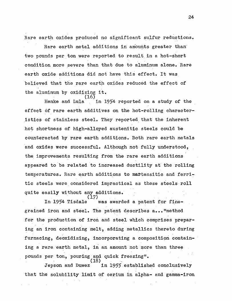
Rare earth oxides produced no significant ~u~fur reductions.
Rare earth metal additions in amou~ts greater than·
two pounds per_ton were reported to result. in a hot-shor.t
condition more severe than that due .to aluminum alone. Rare
earth oxide additions did not have ·this effect. It was .
believed that the rare eartp oxides reduced the eff~ct of
the aluminum by oxidizing it. · (16)
Henke .and Lula . in 1954 reported on a study of the
effect of rare earth additives on the hot-rolling character
istics of stainless steel. They reported_ that the inherent
hot shortness of high-alloyed austenitic steels could be
counteract.ad by rare earth additions. Both rare earth metals
and oxides were successfulo Although not fully unde~stood,
the_ improvements resulting rrom the rare earth additions
appeared to be related to increased ductility at· the rolling
temperatures. Rare earth addit~ons to martensitic and ferri~
tic steels were.considered impractical as these steels ·roll
quite easily without any adclitionso · . . (17)
In· -1954 Tisdale was awarded a patent f_or f·~ne-
grained iron . and steelo The pat~nt d~scribes aooo"method
for the production of iron and- steel which comprises prepar
ing an iron containing melt, . adding metallics theret.o during
furnacing, deoxidizing, incorporating a compositi9ri contain
ing a rare . ·ea~th metal, in an amount not ~ore than thre~
pounds per ton, pouring ·and quick freezingno (18) ·,
Jepson and Duwez in 1955 .establish~d conclusively . .
that the solubility limit qf ce~ium in alpha- and gamma-iron

in the te~perature range 815-10l5°c (1499-1$59°F) lies close
to 0.4 weight per cen~. This finding was in contrast to the
12-15 weight per cent reported by Vogel, .QI?· cit., in 1917. (19)
In 1956 ~ackson presented a summary of the work
which had been performed- to date concerning the use of the ·
rare earths in cast steels •. He commented on the definite
lack of research dealing specifically with the rare earths
in cast steels. With the limited data available, he conclu
ded that mischmetal additions in cast steels improve ductil
ity and impact ·properties but do not prevent temper brittle
ness in a susceptible steel. Ee also concluded that misch
metal additions reduce the _susceptibility to hot tearing,
improve flµidity, do not affect hardenability or weldability,
and can be made most satisfactorily to the ladle in quanti
ties ranging from two to four p01.mds per ton of steel.
He commented on the fact that the precise mechanism
by which the rar_e earths instill the reported imp1 .. ovements
in steels was not known; the . improvements were most · probably
due to a number of factors operating simul t~meou.sly. · . (20)
Tisdale in 1956 obtained . a _Canadian patent on the
composition of rare earth oxides for the production of.iron
and steel. The additive was formed by ••• tlmixing a lanthanon
oxide with 0.02-loO parts of a reductant such as a boride,
borane or sili~ide o.f Group Ila metals, man~anese, chromium,
iron, boron, cobalt or nickel". · (21) · ·
In 1958 Wilson reported on the work of two Russian (22) ·
metallurgists, Tageev and Smirnov • They had reported

26
that two to four pounds of mischmetal per tori fully elimina
ted trAtt-segregation in steels containing Oo36-0o42 per cerit
carbon and 1.10 per cent nickel.
In verifying these results and attempting to explain
them, Wilson, ibid., reported on an investigation in which
5-50 per cent rare earths were mixed with FeS and the mix
ture heated to the melting point. It was fou:nd that the
melting point of FeS was raised from 30° to 270°F (17° to
1,0°c). FeS melts at approximately 2180°F (1193°c). He con
cluded that the rare earths minimize or eliminate sulfide
segregation by raising the melting point of FeS and enabling
earlier solidification of· the resultant sulfides. (23)
Pe~kins and Binder in 1959 studied the non-metalli.c
inclusions produced by deoxidation of steels with silicon,
aluminum, titanium and rare earths. They found that the ten
sile· ductility of ingot steel at 2400°F (1316°c) was signifi
cantly improved .after deoxidation with mischmetal. (24)
In 1959 Singleton reported on a study of the effects
of adding·pure cerium metal to SAE 1035 steel. The heats were
induction melted in magnesia crucible.s. Heats were made under
bot_h vacuum and air, and studied in both the oxidized and de
oxidi zed· conditions. Aluminum was used as the deoxidizer in
the deoxidized heatso Aluminum contents of the deoxidized in-
gots were on the order of OolO per cent. The pure cerium metal
was added in amounts ranging from Oo05 to 0.25 per cent.
The oxygen contents of the steel decreased with in
crea.sing quantities of cerium additions. Cerium oxide

27
inclusion~, however, were conspicuously absent in thi steel.
It was concluded that the cerium oxide which formed--which
was not identified as to type--rose to the .slag phase with
very little remaining in the metal.
Regular sulfur drops were noted. The magnitudes of
the sulfur removals increas~a. with increasing cerium addi.;.
tions. A new type of inclusion was .found to ·be definitely
associated with the presence of cerium. These inclusions
were quite small, complex gray and black in color, and were
not found in clusters. Under polarized l~ght with crossed ni
cols, the inclusions appeared as bright red to orange. ·The
red portions were completely removed after etching with
hyd.rochlo~ic acid, indicating that these inclusions were not
oxides. Further tests indicated that the inclusions were not
nitrides or silicates. Cerium analyses on electrolytically
extracted inclusion residues, b_oth before and after extrac
tion with hydrochloric acid, showed that the cerj_ura species
was completely soluble in th_e ·acid. As Ce 2s3 can exist as
an orange-or red crystal and is soluble in hydro9hloric acid,
the new-type inclusions were iden~i~ied as Ce2s3•
Cerium appeared -to have no effect on.nitrogen content.
A strong reaction between the cerium and the magnesi~ cruci
bles was noted. Rough analyses .on several of the crucibles
••• "indicated a large loss o_f cerium into the crucible in
amount equal to a good fraction of the cerium added".
This is the gist of the work on the rare earths in
steel. Further references are l~sted in the articles cited.

V. !.ti§ RARE . EARTH ELEMEl\i'TS
1. Electron Con:figuration
There are two rare earth series as positioned in the
periodic table. The Lanthanide Series consists of the ele
ments o~ lanthanum through lutetium--atomic numbers 57
through 71--and appears in <;rroup 3a of Period 6. The Actin
ide Series is composed of the elements of thorium through
californium--atomic numbers 90 through 98--and falls under·
Group 3a of Period 7.
These rare earth series are group~d together in the
periodic table due to electron configuration. In each 6f
these seri~s, the third outermost electron shell undergoes
transition. In the Lanthanide Series the 4f levels of the N
shell are filled in the transition. In the Actinide Series
the 5f orbitals of the Oshell are filled. A transition
series usually involves the fil.ling of the second outermost
electron shell. As chemical behavior is determined· almost
exclusively by the action of the two outermost electron ·
shells, it · ~ollows that the rare earth elements behave very
nearly the same chemically and as .a consequence are very
difficu1t · to separate. In this invest_igation, we are con
cerned with the elements of the Lanthanide Series.
2o Occurrence, Extraction, and .Separation (9)
The name rare earth is a "misn9mer" • These elements
are neither rare nor are they earths. They are metals just as
iron is a metal. They are not rare if this denotes a · lack of
abundance. When conside1•ed as a . gr.oup, they are more abundant

than zinc., lead, tin or molybdenum. A compar.lson of the
relative abundance as a perce.ntage of the · earth• s crust ts (9)
as follows . •
Rare Earth Elements Zi.nc Lead Tin Molybdenum
0.005 per cent 00004 00002 0.001 0.001
29
The principal source of the rare earths is the mineral
monozite, found as an alluv:lal sand in Brazil, India, and
domestically in the Carolinas, Florida and Idaho. The mineral
is essenti.slly· a complax phosphate, containing up to 70 per
cent cerium with other rar~ earths and four to nine per cent
thoria. Bastnaesite, a hydrated flu"?carbonate, is found in
Colorado and California. Other mineral sources are allanite,
cerite, gadolinite, samarskite and xenotime.
The firs~ relatively clean separation wa~ performed by
Berzelius in Sweden in 1903 when he isolated cerium. The last
rare earth ele~ent reported to be separated was promethium-
then called illinium--which .was reported to have been isola
ted by a group of American res:earchers in 1926. _Ther~ is some
question, hov,ever, as to· whether promethium occurs in .nature
and whether it has ever been separated from . a natural .mix
ture. Twelve isotopes o~ promethium have been identified as
products of nuclear reactions • .
Separations ·of high purity were virtually unknown
until the 1940 1 s. Then great interest in the properties of
the rare earths developed rapid~y -when it was discovered that
the rare earth elements form a _large percentage of the ashes

30
or nuclear fission.
Until the late 1940 1 s, the separation of the rare
earths from one another had depended on fractional crystal- .
lization. This tedious method was then improved upon by the
introduction of separations depending upon the oxidation or
reduction or some of the elements to other than the tri
positive state. Solvent extraction and ion-exchange methods
of separation also appeared in the late 1940 1 s. The ion
exchange method is applicable on the tracer scale up to 100-
gram lots with impurity contents on the order of less than
one part per million.
On the basis of separation, the rare earths are divi
ded into three groups: the cerium group, the terbium group,
and the yttrium group. The cerium group includes Ce, La, Pr,
Nd and Sm. The terbium group consists of Eu, Gd, Tb and Dy,
and the yttrium group of Ho, Er, _T_m, Yb, Lu and Y. The
groups are so named because of the preponderance of cerium,
terbium, and yttrium in the mixtures 0£ the rare earth
elements obtained from the minerals in preliminary s~para
tion processes. Although not a rare earth, yttrium--atomic
number 39--is classed with the rare ear.ths because of 1 ts
general occurrence with the rare earths and its similarity to
them. Mischmetal and the commercial rare earth oxide mix
tures consist essentially.o:f the elements of the cerium
group.
3. Physical and Chemical Properties
Some of the more important .physical properties of the
rare earth elements are listed in Table I. The structures,

31
TABLE I (9)
PHYSICAL PROPERTIES OF THE RARE EARTH ELEMENTS
Melting Boiling Density Atomic Atomic Point Point (70°F)
-Element Symbol · Number Weight (°F) (°F) gw/cc
Lanthanum La 57 138092 . 1580 3275 <-6.19.4 P-6.180
Cerium Ce 58 140.13 1420-1470 2550 ~-6(1?8 . 172,-1760
P-6. 810 Praseodymium - Pr 59 140.92 <-6.810 Neodymium. Nd - 60 144027 1475-1650
___ .. _ c:C-7 .004
Promethium Pm 61 146 (?) ----- _ .. ___ Samarium. Sm 62 150.43 2460 6.93 Europium Eu 63 · 15'2.0 2000-2200 ----- 5.244 Gadoliniu~ Gd 64 . 156.9 ----- 70948 Terbium Tb 65 . 159.2 ----- 8.3i2 Dysprosium Dy_ . 66 162.46 ----- 8.5 2 Holmium · Ho 67 164.94 ----- 8.764 Erbium Er. .. 68 167.2 2280 (?) . 9. 164 Thulium Tm 69 16904 ----- ·9.346 Ytterbium Yb 70 173.04 3275 (?) 7.010 Lutetium Lu ·71 174.99· ----- 9.740
32
lattice parameters, and atomic ridii are gi~en in Table II.
The crystal structures and densities were: determined by
reducing chlorides of the purifled rare earth metals .. with
potassium. and ~aking x-ray powder photographs of the result
ing mixtures. The know.n . spectra of · potassium chloride .serve·d
as the calibration. The at~mic radii, with the exception of ·
europium, ytterbium and samarium snow a decrease with
increasing atomic number when the elements are.in metallic
form. This is the "lanthanide contraction" resulting from
_the increasing ·nuclear charge. In metal~ic form, all of the
rare earth elements except europium, ytterbium and samarium
possess atomic radii characteristic of tri-positive cations.
· Europium,_ ytterbium and to some extent samarium approach the
radii expected of bivalent metals. In compound forming
tendencies, the normal oxidation state is the tri-positive
state. In addition to europium, ytterbium and samarium,
however; oxida~ion states of ,'2 have been reported for lan
thanum, cerium,- praseodymium, neodymiu~, gadolinium and ·
thulium. ·Oxidation states of ,'4 have been reported f~r
cerium, praseodymium, neodymium and .terbium. Praseodymium
alone exhibits an oxidation state of /.5 •.
All of the rare earth metals pos~ess an unus~ally . .
strong chemical"affinity for the non-metallic elements nor-
mally associa_ted with steel: sulfur, oxygen, hydrogen, ni tro
gen and carbon. They also alloy readily with most common
metals, in many cases forming significantly refracto~y _inter
metallic compounds with the parent metal. With the many

33
TABLE II {25)
CRYSTAL STRUCTURES AND ATm~c RADII OF THE RARE ElL~THS
Crystal *
Atomic Element Structure Lattice Parameters Radius
*
a c ~-La h.c.p. 3.754AO 6.063A0 l.870A0
(3 -La f.c.c. 5.294 1.872 <-Ce h.c.p. 3.65 5.96 1.81 s-ce f. c ·. c. 5.140 1.817 llC.-Pr h.c.p. 3.662 5.908 1.824 oC-Pr f.c.c. 5.151 1.821
-Nd h.c.p. 3.650 5.890 1.818 Sm Eu b.c.c. 4.573 2.042 Gd h.c.p. 3.622 5.748 1.794 Tb h.c.p. 3.585 5.664 1.773 Dy h.c.p. 3.578 5.648 1.769 Ho h.c.p. 3.557 5.620 1.759 Er h.c.p. 3.532 5.589 1.748 Tm h.c.p. 3.52~ 5.564 1.742 Yb f.c.c. 5.46 1.933 Lu h.c.p. 3.509 5.559 1.737
h.c.p. is hexagonal closest packing; f.c.c. is facecentered-cubic; b.c.c. is body-centered-cubic ·

34
possibilities for reaction .with the various constituents ih
steel, it is not surprising that a detailed explanation or· the behavior of the rare earth elements in steel has not
been forthcoming.
Table III lists the -~~operties of the rare earth
oxides and- Table IV the properties of - the rare e_arth sulfides.
The properties are compared with the properties of some com
mon oxides and sulfides encountered in steelmaking. The
values of the standard heats of formation given are for 25°c
and one atmosphere. Lack -of data prohibits the calculation
of free energy of formation values at the temperature of mol
ten iron. The values given do give an indication of what
might. be expected to be the relative deoxidizing and desul
furizing powers of the rare earth elements as compared to
the other · elements listed.
·From these data, it would be expected that the rare
earths have a very strong tendency to form oxides· and _sul
fides in molten iron. The oxides would . be expected. to form
more readily than the sulfides necessitating deoxid~tion of
the bath prior to the rare earth additions· if desulfuriza~
tion is to be anticipa_ted. Both the- rare earth oxides and
sulfides have densities less than iron. The normal reac-
tion product~ of the rare earth elements with sul~1f are
the sesquisulfides (RE2s3), and there is evidenc~ that these
are the principal sulfides formed by the rare earths in
molten steel. All of the rare ear"th elements form oxides of
the type RE2o3 • However, the only rare · earth oxide tentative
ly identified .as resulting from mischmetal ~dditions to steel

3~
TABLE III (26)
PROPERTIES · OF THE RARE EARTH OXIDES
Heat of O Formation, A!ii Melting Boiling Gram Calories
Density per Mole . Pgint Pgint Com12ound gm,Lcc t 22°C:1 1 atmo l c . . c
La203 60 51 -458,ooo . 2315 4200
Ce 203 609-700 -456,ooo 1692
Ce02 7.3 -233,000 2600
Nd2o3 7.24 -442,000
Pr2o3 6.88 -444,500 d! Sm203 . 7o43
___ .. _ .. . .. ___
Eu203 60 55-7 042 .. ------Gd203 7.41
______ ,..
Tb2o3 Wl919 ____
. Dy203 7.81 ------Er203 8.64 ------ ·----Tm2o3 ------Fe304 5ol8 -267,000 153~d.
FeO 5.7 -63 ,.?00 1420
MnO 5 0 43-5046 -92,000 1650
Al2o3 3 • 5-3.9 -389,000 2050 3500
MgO 3o 58 -143,840 2800
Fe 7.86 1535 · 3000
d. indicates decomposition upon melting

Compound
La2s3 Ce2s3 CeS 2
Pr2s3 Nd2s3 Sm2s3 Gd2S3 Fe3s4
Fe2s3 FeS
· MnS
Al2s3 MgS
TABLE IV (26)
PROPERTIES OF -THE RARE EARTH SULFIDES
Density gm/cc
4.91:-5.00
5'o02
.5.04
5.18
5.73 3 .8 ·
. 4~55
4.3
4.84
3.99
2 .• 02
2.79-2.85
Heat or Formation, AH~ Gram-Calories
· per Mole ( 25:0 c ,· 1 atm. L
-306,800
-298,?00
-153,900
-281,800
-22~ 720
-47,600
-~21,600 ~
83·,000
Melting Point
Oc
2100-2150
1925d.
2200d.
1900
-----d.
1193
·1100
do
Boiling Point
oC.
d.
1550 "# . subl. ·.
* d. indicates decomposition upon · m~·lting or boiling
# subl. is sublimation
36

37
i ~ Ceo2 • ~ne·~lman, .Qn• cit·., observed a ceo2 . type s·tructure
in the x-ray diffract~on patterns made fro~ slag-scum
samples. The·sesquioxides are also thought _to be a major
reaction produc~ resulting from mischmetal additions to
steel. Lanthanum does not exhibit the f4 oxidation state.
In the absence of exces.sive oxygen in molten ~teel,
the rare earth elements are believed to form· sulfides with
melting points above the melting point of iron, and being
of lesser densities than iron, these sulfides float to
the slag phase·where they are removed. B~ing refractory,
the remaining sulfides occur as spheroidal, well dispeised
particles which do not elongate during hot rolling as do
the sulfide inclusions in untreated steels. Snellman, £m•
cit., found that under oxidizing conditions, the rare
earths are oxidized after a period of time with the sulfur
reverting to the metal phase.
The detrimental effect of extremely small percenta
ges of hydrogen in steel is a ·well es.t9:blished fact ·. The·
· rare earths have a strong affinity r·or hydrogen •. The·
reaction between t.he rare earths and.hydrogen is exothermic
wh~le the.reaction between iron and hydrogen is endothermico
Regardless of the temperature, the rare earths are capable
of dissolving tremendously greater quantities of hydrogen
than can-iron. The solubility of hydrogen in mischmetal _has (9)
been reported to be 2000 times greater than that of iron ·,
at 2000°F (1093°c) and over 60,000 times as g!eat at 750°F
(390°c). The melting points of the.rare earth-hydrogen

alloys are well above those of the corresponding pure (9) .
metals •
The rare earths are strong carbide f9rmers. The car
bides are hexag~nal crystals of the general form ~Ec 2• The
rare earth carbides can be prepared quite readily by
reduction of rare earth oxides with carbon but thermodyna
mic data are lacking. In plain carbon steels to which rare
earth _metals had been-added, however, varying carbon con-
tents apparently had no significant effect on desulfuriza(14)·
tion •
The rare earths have a strong affinity for ni£ro~en
at high temperatures. The-reaction between ammonia and the
rare earths produce rare earth nitrides of the type REN by
direct union with the metal at temperatures in the vicinity
of 980°c. There is little data available on the properties (9) .
of the rare earth nitrides. It is believed that nitrogen
control may be a. major .factor in the improved properties
attributed to the use of the . rare earths in steel.
The atomic volumes of some of the rare earths -are
compared with some . other m~tals in Table V. The large vol
wnes of the rare earth atoms as compared to .the volume~ of ·: · . (10) ·
the iron atom is considered to be the reason for the
improved oxidation resistance which results when rare
earths are added to steel. The atomic volumes of the rare
earth elements are greater than the volume of the iron .oxide
molecule with the result that the rate of diffusion is
restricted.

Element
Be Fe
·Cu Mn Mo w Al Au .Ti Si
. Zr Sm Ce Pr Nd La Ca
TABLE V (10)
ATOMIC VOLUMES
Volume · cc/gm atom
4.96 7.10
· 7.11 7.4 9o4 . 9.53 9.99
10.22 10.6 11.7 14.32 19.4 20.3 20.5 20.5 22.6 25.86
39
40
4. Appli~ations
Since the late 1940's, the rare ·earths have been
utilized in -the production of nodular cast iron. The rare
earth elements _serve to deoxidize, desulfurize, and act as graphitizers. The rare earths have found wide use in the
magnesium and aluminum industries as alloying elements.
Other applications vary from the use of rare earth fluorides
in cores of arc carbons to the use of mischmetal alloys in
cigarette lighter flints.
The most -common form in which the rare earths are
furnished for metallurgical use is the alloy called mi~ch
metal. The ·approximate composition of ordinary mischmetal as
extracted from the ore is:
Ce La Nd Other Rare Earths
50-55 per cent 20-30 15-17 8-10
The rare earths in mischmetal are primarily from the cerium
group. There are several varieties of .mischmetal commercially
available. The · tan-cer-amp No. 2 used in this study is com
posed of 30 per cent lant~anum_minimum, 45 to 50 per· cent
cerium, five per cent iron, and -the balance other rare
earths. The manufacturer claims greater benefits are derived
from the use.of this alloy as an additive to steel than from
the use of ordinary misch~etal. The higher lanthanum content
is said to be. one £actor. Lanthanum melts and boils at ·hig~er
temperatures than cerium. Lanthan~m sesquioxide and sesqui
sulfide are stable at higher temperatures than the corres
ponding sesquioxide and sesquisulfide of cerium. It should

41
be noted,_ however, that Ceo~ melts at a temperatur~ (26ooot)
considerably higher than the sesquioxides ·or either cerium
(1692°c) or ·lanthanum (.2315°c). The five p~r cent iron is
added to lower ~he melting point from 1490°F (810°c) to
about 1200°F (65o0 c).
There are other alloys containing mischmetal avail
able--each developed for a speciflc application. Lan-cer-amp
No. 23 contains 25 per cent mischmetal and 10 per cent
zirconium with the balance being low carbon iron. In this
_study, only ordinary mischmetal and Lan-~er-amp No. 2 were
used for the rare earth metal additions.
The. rare earths also are available in a number of
salts. Of _ these, the rare earth oxides and fluorides have
found application in steelmaking. These salts contain approx
imately the same proportions of the rare earth elements as
ordinary mischmetal. The rare ~arth oxides do not act as
desulfurizers but have been reported by several irivestiga-(7) (13) (16)'
tbrs to increase markedly the hot workability of
some stainless steels. Russell, .212• · cit., repor~ed tl'~.'at rare
earth oxide additions to· alumirium~killed plain carbon steel
reduced hot shortness attributed to residual aluminum .con
tents. He postulated .that the rare earths oxidized the
aluminum. A detailed investigation into the mechanism of the
rare earth oxide reactions in molten steel has not, as yet,
been forthcoming. Rare earth fluoride mixtures have been (13)
reported to improve ingot surface quality a.nd malleability
or austenitic titanium steels.

42
!h HOT . SHORTN'ESS
Hot sho·rtness, sometimes called 'red shortness, · is ·th~
tendency of ·certain metals to exhibit brit.tleness when
worked above a.red heat. Sulfur and oxygen are known to be
major contributors to hot shortness. The role of coppe;t' in·
hot shortness h~s, through .th<3 years, · been the subject of
much discussiono Aluminum has been reported . to be a cause or hot shortness in aluminum-killed steelo
1 2 Effect of Sulfur
Sulfur ·has been known for many ye_ars to cause hot
shortness in iron and steelo One theory or the mechanism of
hot shortness as caused by sulfur was first postulated by (27)
Wohrman o He attributed hot shortness to the passing of
the iron or steel through the A3 transformationo He was of
the opinion that sulfur was soluble in gamma-iron at the A3 transformation to an ex.tent sufficient to cause embri ttling.
of the gamma-1r.ono He based his theory in part on the dis-(28) · ..
covery of Sauveur and Lee ·o:r the ph~nomenon of "critical
plasticity" at the A3 transformationo Sauveur ar;i.d Lee had
found that when a _ bar of iron or low carbon steel is ·heated
at the center of its length to a temperature exceeding the
A3 · transformation temperature and then ~wisted, the . twisting
occurs not at the center where. the bar is hottest,· but
rather at two points equidistant from the center -where the
bar is un~ergoing the A3 ~ransformationo Wohrman believed .· '• .
that hot shortne.ss disappeared at higher temperatures
because of the greater plastict.ty . of the gamma-iron at higher.

temperatu~es. This theory, however, has not ~ained .wide
acceptance.
Today, the accep.ted t?eory is, that in the absence
43
of sufficient m~nganese, iron sulfide precipitates upon
solidification as thin films in the primary grain bounda
ries. The predominant sulfi<Ie is thought to be FeS. FeS
forms an eutectic with iron. The Fe-S equilibrium diagram is
given in Figure 1. -The melting point at the eutectic compo
sition of 44 atomic per cent sulfur is given as 988°c. Pure
FeS melts at approximately 1190°c. Upon ~olidification,
this low-melting eutectic is precipitated at the primary
grain boundaries. These films become liquid at hot-working
temperatures and the metal cracks at the grain boundaries
_when worked in the hot-short region. Hot shortness occurs
only in a temperature range and disappears at higher tem
peratures. This upper limit of _hot shortness is thought to
be the result of the molten sulfide being dissolv~d by . the
gamma~iron which then regains· its continuity and plasticity.
Manganese is an essential ingredient in s_teel- because
of its very strong affinity for _ s~lfur. Manganese and· sulfur
combine to form MnS which has a much higher. melting point
than the Fe-FeS eutectic. 1\mS forms as s_eparate, dispersed
globules which remain solid at. rolling temperatureso Low
carbon steels contain a minimum of Oo25 per cent ·manganese · • · (30)
for maximum sulfur contents of 0.050 per cent. Cain . re-
ported that in the absence of manganese, hot shortness will
be present i:r the sulfur content exceeds 0.010 per cent.

CJ 0
w"" ;::f. :,
I-<( ~ u.J a.. I: w ~
17(0
1600
150(}
1400
1300
1200
1100
lOOQ
900
800
0
44 0
.V) .
~
! 11ioo
1 \ ', /, \ I \
\ \
s ',
' ' I I
"' V)
Lt
1
I II
. -- - - 7.290 - - -- - - - - I II I II MAGN. THANSF.
...
' ti 700 '--~-'-~--'~~--~--L~~~~--"-~-11___._ ___ ~--'"---~------
o Fe
10 ·20 30
Figure 1.
40 50 60 70 ATO:.i!C PER C.E:NT SULFUR
(29) The . F.e-S s'ys·tem
s
..
44

45
2. Effect of Oxygen
A more detailed treatment of hot' shortness takes into (31)
consideration the role -of oxygen. Hilty and Crafts stateq
that ••• "all oxide and sulfide inclusions in steel·, excluding
mechanically entrapped matter, result from modifications
of the be .. sic Fe-S-0 system';.• The FeS-FeO system is given in
Figure 2. There is an eutectj_c between FeS and FeO at approx
imately 55 molecular-per cent FeS with the eutectic tempera
ture being at 940°c. In the presence of appreciable quanti
ties of sulfur· and oxygen, and in the absence of sufficient
manganese to tie up the sulfur·, it would be expected that
the FeS-FeO eutectic would have a strong tendency to precipi
tate at the pr1.mary grain boundaries and lead to a hot-short
condition. In reality, the compound FeO does not exist as
such. What was once thought to be the compound FeO is now 00
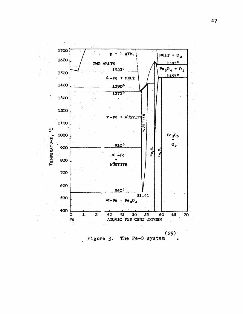
lr..riown to be the ph2 se wusti te. The equilj.brium diagram of .. the Fe-0 system is given in Figure 3. The wustite phase de-
composes eutectoidally into.alpha-ir~m·and Fe304. The melting
range of ·wi.istite is 1371-1424°C~ What are commo~ly r~ferred . . . . . "
to as FeO inclusions in ir·on and ~teel a.re really wusti te
and appe~r as gray-to-black particles in the matrix. Cain,
.9.ll• cit., found that oxygen contents up to 0.20 per.cent do
not cause hot shortness in high-purity iron if the· sulfur
content -is below 0.010 per cent.
3. Effect of Copper
Through the years, copper was reported by some inves
tigators to cause hot shortness and by others to reduce it.

(.) 0
9'
llJ tt :::> ... ~ -
141 a. t: w ....
1800
1600
1400
1200
1000
800.__~--------~~--'"---~~~...£--~~~--~~~__, 0 PeO
20 40 . 60 80 K>LBCULAR PBR CEf\T Fe S
Figure 2. (32)
The FeO-FeS system
100 ___ _ FeS
•
46
47
1700 1 ATM. 1 p •
' 1600 I 'rt«> MBLTS . ' 0
' 1500 0 '-Pe + MELT
1400
1300
12CX)
Y-Pe + wflSTIT
1100 0 ~ 0
.... 1000 Fell:, lU + ex :) 0 Oa· ....
900 ... < 0 0 ~ w . «:. -Pe " 41 a. u.. 1L. . 2:.
800 + ..... t- wtlSTITB
700
600
500 51.41 <-Pe + Pe 3 0 4
400 · 0 1 2· 40 45 so 55 60 65 70 · Pe A'IDMlC PER CENT OXYGEN :
( 29) Figure 3. The Fe-0 system •

4-8
Cain, ibid o, found that copper contents rang~ng :from ·-0.05
to o. 5 per cent were of minor importance ;n affecting · hot-
shortness in high-purity iron; in a few in~tances, high . . (33)
copper c·ontents. tended to reduce hot shortness. Cornelius
in 1940 published, in a.book on the errect of copper in iron
and steel, the results of a·~ ~nvestigatiori by F. · Nehl.- In
the investigation, Nehl subjected ·a series of low carbon
steels with varying copper contents to a hot~bend test at
1050°co He showed that copper leads to a hot-short condition
~hen present in amounts in excess of approximately Oo08 per
cent. It is to be noted that there was suff'icient manganese
in each steel to eliminate the effects of sulfur on hot
shortness~ The Fe-Cu phase diagram is shown in Figure 4.
4, Effect of Aluminum
Aluminum has .been reported to be a cause of hot
shortness. Russell, .Ql2• ill·, r_eported that hot shortness
in low and medium carbon steels increased with incre.asing
residual aluminum contents i_n aluminum-killed heats. Alumi-
· num is extensively soluble in iron (Figure 5). Tpe a~pha
solid solution ex~ends to appro~l~ately 22 atomic per·cent
aluminum at room temperature. No eutect:i.c occurs on the
iron side ·of the diagram. It .is one of the objectives of
this research to study the effect or residual aluminum
contents . on hot shortness in ingot iron.

49
TABLE VI
THE INFLUENCE OF COPPER CONTENT ON THE CRACKING OF (33)
STEELS SUBJECTED TO TEE BEND-TEST AT 1050°c
Per Per Per Per Cent Cent Cent Cent
* Steel Carbon Manganes~ Sulfur Copper Bend-Test
1 Ool2 o.64 00022 Oo02 -2 0.13 o.66 0.016 Oo03 3 Ooll 0.33 0.037 0.04 4 0.11 0.32 0.026 0.04 . 5 Ool2 0.3, 00030 Oo04
. 6 . 0.05 0.32 0.035 0.04 7 0.10 0.33 00031 0.04 8 0.16 0.41 Ool02 . 0~04 9 Oo04 0.30 00037 0.04
10 . Ool3 0.3; 00026 ·oo05 11 Oo07 0.34. 0.020 0.05 12 0.16 0.38 0.024 0.05 13 0.05 Oo32 OoOg5 Oo05 14 Oo08 0.35 OoO O Oo05 15 0.06 .0.32 00038 Oo06 16 0.09 0.33 00021 0.06 17 0.10 0.39 0.031 0.07 18 0.18 0.70 0.032 Oo08
- 19 0.07 0.62 0.026 0.08 20 0.06 0.32 0.02, Oo08 21 0.09 0.34 0.030 0.08 • 22 0.04· 0.31 0.025 . 0.08 .. 23 0.05 0.26 - 0.026 0.08 24 Oo04 0.26 _0~023 0.08 25 0.07 0.32 0.040 0.09 26 0.07 0.27 o_.019 0.09: • 27 0·011 · 0.61 0.020 0.10 • 28 0.06 0.35 o·.021 - 0.11 • 29 0.06 0.23 0.032 0.13. •
- .- 30. 0.18 0.51 0.021 0.15 I-(continued on next page)
* " - no cracks; • cracks visible with magnifying glass; f cracks·. visible with naked eye; - ~ ; · strong crack formation; ff J very strong crack ~ormation

·50
TABLE VI (can't.)
Per · Per Per Per Cent ·cent Cent Cent
Steel ·carbon Manganese Sulfur Co1212er Bend-Test
.31 Oo05 Oo30 0-0022 Oo15 I 1' 32 Oo24 0.78 0.020 0.15· /. 33 Oo32 0.82 0.016 0.16 f f I-34 0.11 .0.52 0.043 0.16 r ;. il 0.12 0.46 0.025 0.17 . I- I-
0.09 0.55 0.032 Ool9 r f 37 Ool8 0.78 0.029 0.19 I- f 38 0.18 o.66 0.037 0.21 /. I-39 Oo21 1.09 0.035 o·. 23 I- I-40 0.07 0.41 0.032 Oo24 I-41 0.05 o~-38 0.025 Oo25 0
42 0.09 0.46 0.039 0.25 0
43 0.09 0.52 ..... -..... 0.30 /. I-44 0.24 0.89 ----- 0.50 r

<..) 0 ~
w o= ~
~ < Q: w ~
l: 111 +-
51
1600
1500
1400 1403°
1300
1200
?f
1100 0
1083 - \
1000 \ \ \ I
900 \ 910° \ I/
I I 0
800 -- - - - - - - - - - - - - 'Z..5.9.
0 - - - - - - - - - - - - . -- - . 7 6 8 °
MAGN. TRANSF. 100 o.35
600 0 Cu
10 20 30 4(J 50 60 70 ATO~!IC PRR CE~T IRON
80 90 100 Pe
Figure 4. ( 29)
The Fe-Cu system •

u • ,.. la.l
°' :::, t< ~ w a. r Id I-
1600
1500
1400
1300
1~
1100
1000
900
800
700
600
500
400
910° J
I I I
769° I - "" I ........_ I
/ ',: \ I ,,
tAGN. TRANSF4
ac :~ •; ./J, \ I '. \ I \ \ I . I I \ I
......
' ' ........
' '
~
" u. I
1/ I I I I I
- ~
99.1
: \ I 300 L---....&.--~....._...___....._...._--.&. __ ~--~--L..:--~,__._ .......... _.... ___ ~__..__~--
0 . 10 Pe
~ 30 40 50 60 70 80 • 90 100 An)MIC PBR CE~T ALOMINtJ.t Al
Figure 5. (29)
The Fe-Al system •

53
VII o · METHODS. QE. EVALUATING HOT WORKABILITY
The hot·worki~g of iron and_ steel 4ates back to ·
antiquityo It was not until the .1920 1 s, however, that s·eri
ous efforts wer~ made to devise methods of evaluating the
hot workability of irop. ·and steel in a quantitative mannero ·
Prior to this, the procedure had been 'that of trial :and
error.
1. Hot-Bend Test
One method of evaluating hot workability is the hot
bend test. In this test, a bar of iron or steel is heated to
a given temperature, quickly removed from the furnace,
secured in. some manner, and. struck with a mallet. Cain, .Qn•
..911., useq such a method in 1924 to evaluate the hot short- .
ness of iron specimens. After the hot bars were secured in
an anvil, he bent them back and forth through 186° as rapid
ly as possible. If a bar fractured during cooling through .
the hot-short region it was taken to be hot short; ~fit did
not break, it was assumed to. be f~ee .ot:· hot shortne·sso The
· hot-bend test is still used as a rapid_ qua~i tative te.st of
hot workabilityo Nehl, .212.• cito , . subjected his copper.;.bearing
steels to ·a single bend and obtained some very useful resultso
The test, however, can not be ~xpected to subject the test
specimen to stresses which closely resemble those encountered
in forging or _hot rollingo
2. Single-Blow, Drop-Hanimer Test · (34)
Ellis in 1933 t~·sted the forg~abili:ty 0£ diff~r-
ent steels at various elevated temperatures by means of a

54
single-bl9w, drop-hammer test. He prepared t~st cylind~rs
which were one . inch in diameter and one . inch in length. The .
specimens were heated to the testing temperature, quickly
removed from the .furnace, and placed on the anvil of the
drop hammer. The cylinders were then subjected to a single
blow of 520 foot-pounds of energy. By testing a series· o:f
specimens of a given steel at various temperatures, a quan
ti-tative measure of the steel's hot workability could be
. obtained. Although this test enabled the measurement of
quantitative data for the first time, the hot workability
was measured for only the instantaneous force of a single
blow. Correlation was in ·many instances lacking in practice,
particularly when a metal was subjected to repeated blows
by the forge hammer or when the metal work hardened. The
instantaneous stresses applied could not be expected to
closely parallel the continuous. shear stresses encountered
in hot rolling • . The test was, however, the first of_ its
nature to receive wide recognition, and· a considerable
amount of-useful data was obtained from its use • .
3. Hot-Twist Method
The test which appears to provide the best evalua
tion of hot workability involves the twisting of test bars (35)
at elevated temperatures. Sauveur is credited with orig-
inating the t~st in the 1920 1 s. He round that steels in .
torsion exhibit changes of torsional strength while in the
blue-brittle range and when passing thr.ough t.heir critical
points. His experiments were all conducted at temperatures

below 2000°F (1095°c) and at very slow twisting speeds.
The hot-twist method was improved upon at Globe
Steel Tubes Company in 1938. By 1944 over 7000 tests had
been made at their laboratories to determine the best condi-
tions for the piercing of a wide variety of carbon, alloy
and stainless steels. {36)
In 1944 Ihrig described the method used at Globe
Steel Tubes Company and some of the results obtained.
Bars of steel 22-24 inches in length are prepared by
forging 5/8-inch bars from large billets and cold drawing
to 9/16 inch. Figure 6 is a schematic diagram of the appara
tus. The bar A is inserted in the furnace B. One end or the
bar is clamped in the chuck C and the other end is held
in the heavy dog D. The bar is thus free to expand through
the bearing E, but it is prevented rrom rotating on that end
while the other end is rotated by the chuck. When the torque
is applied, the dog makes contact with the stop F and ener
gizes the electrical counter G, which ili turn records the
number of revolutions made by the chuck by means of the con
tact at H. When the bar breaks inside the furnace, the dog
drops away from and breaks contact with the counter circuit,
and an accurate count of the number of twists to failure or the bar being tested is recorded.
The bar is soaked 20-30 minutes at the test tempera
ture. The furnace temperature is controlled by a regulator
and measured by a pyrometer. The furnace is mounted on a
movable carriage which facilitates easy removal 0£ the

r--::::::.::. ... --:- ..... , . t f, · ' .!.._~ ·) . , t.- .
j j .
L-::~~~M~_r t ·~
r-·-:_·--·~ :n:-, J .. - --~·- :-· . .. ··· · ···· - · -,.··-···
. ,h::!~:: :::'1NALS r,· : . .ft..ouNTE_A (G)
' . i ; : ,. I .
. ; I
LJ/
In 71Jst Pos/tio11. V2" Di-..X 24" .
CHUCK (C) Standa..rd three
Jaw, n.8 R. P./vl.
4- ·· - · · ··
......... ~ .
.::~\':-~ t :; : \: ;' fuRNAC~ . (8) ~W ... Wi</e X 101/9" lonJ
. x 8~ .. Hi9h .
. ~AP,IN§ PL c'!.Tc ,!;:) r---- sv,ports t~t.t bu l:,,,t
I a t f~rr,,i(S /J,11 -(0 tn.o"e ! when e"fa~ dinJ
~E(; END_
I d . t·
t vrin(f ;;,a '"•·
' J . . ~
·, Oofir (D)
f C/o,,,f;~./ ·"ii9ht o,, e~J
I. of .ba.r. s top kflers h:u +rem · · rot;-tinj Jvrin9 t~5t t:lml 11.'ti.Ke~· con(o.ct -tor electric. -c.oun ter: '
t..or keJ M plo c e · a~ring . t~st bu!: rnovi2.tie !o p•rnii.t irisertinJ ,·:wd rem ov ,n; rest bo.r!,. .
Figure 6. (37)
The hot-twist apparatus •
. PERSPECTIYf
__QE.f~~
;6 .. ,
57
broken specimens. ·The - chuck operates at 128 -revolutions- per .
minuteo Thus the bar, -after accurate heating, is rapidly
and uniformly worked by twisting until fr~cture occurso
The bar is held at temperature in the furnace while being
twisted and .actually rises slightly in temperature from · the
working during the testo By rnaking a series or tests· ·on .the
same heat of a given steel at different temperatures,
curves can be drawn which reveal the temperature or optimum
hot workability of the steelo . (38)
Clark and Russ used a similar_ hot-twist test at
Timken Roller Bearing Company. Their apparatus was essen
tially the same as that described by Ihrig, ~o, with the
exception that their apparatus also had a torque-measuring.
device. There was an extensive discussion of the hot-twist
method at the October, 1946 meeting of the Iron and Steel
Division of the American Institute of ·Mining and Metallur(39)
gical Engineers 0 .
Perhaps the most signi.fi~8:nt feature of the test is
that the metal is subjected_ to. C(?ntinuous shear stress·es as
are encountered in ?Ot rolling. The temperature of the max-. . (38)
imum .number of twists before failure is believed to very
nearly represe~t the equi-cohesive temperature of the ·_ metal
under _test. The previous heat treatment of the metal is
immaterial e.s t.he bar is soaked at temperature in the fur
nace before.twisting. The rate of d~formation can be re~ula~
ted. Above a certain critical twisting speed, ·the rate of

5'8
tvdsti._pg has · lit.tle effect on results. The ~quipment involved . . .
is simple and inexpen~i ve, the test requires 11 ttle time, -·and
quantitative ·results may be optained.

VIII. EXPERIMENTAL .. PROCEDURE
. 1 o Mal ting Technique
59
An Ajax-Northrup 17-pound, tilting-type induction·
furnace was used .for all of the heatso The high~frequency .
power source. was a 20-lr~l.owatt, Ajax-Northrup hydrogen-~ype; ·
mercury spark-gap convertero ·_Magnesia crucibles were used
for all heatso Powdered magnesia (Normag) was· packed be
tween the crucibles and the mica insulating sheetso
The furnace was covered with two insulating bricks to
r~duce heat losso Adjoining semi-circular sections were cut
in the bricks to facilitate the making of additions and ·the
taking of temperature readings. The furnace assembly and con
verter unit are shown in Figure 7o
The ingot mold was made entirely of graphite. Two
machined gr~phite cylinders 12 inches in length, with an in
side diameter of 1 3/8 -inches an~ an outside diameter of
1 ·5;8 inches, were joined together by a four-inch machined
graphite cylindero The 12~1nc:P, ·cylinde~s·were machined on·
one end to .an outside diameter o:r 11/2 inches fo:r a d~s
tance of 2 1/8 inch.es from the end •. The four-inch joining
section, with an outside diameter of 1 3/4 inches, was ma
chined to ~n· outside diameter of 1 9/16 i~ches to provide a
secure fitting • . A. flat graphite .disk was used for the mold
bottom and the _pouring spout, with a 1 3/8 inch opening, .was
machined from a 3 1/4 inch diameter graphite cylindero The .. disassembled ingot mold is shown in Figure 8.
Temperature readings were taken with a direct~reading ·

60
Fieure 7. .Furnace assembly and converter unit.

61
Figure 8. Ingot mold assembly.

62
Leeds and Northrup optical pyrometer of the_ ~isappearing
filament type. ·As a check ot. the accuracy :or the pyrometer,
readings were taken on a number of preliminary heats when
the metal had j~st become mol-ten. The readings were always
in the range from 2775° .to 2790°F. The melting point of iron
is 2795°F (·1535'°C). Readings a_t the melting points or ·s_ubse-.
quent heats were also in this range. Ten deg.rees Fahrenheit
were therefore added ·to all readings and are recorded as
such. On this basis, an accuracy of no greater than ·~ 15°F
is ~laimed on the temperatures recorded. _Before taking a
reading, the thin slag cover was always parted to insure
sighting directly upon the molten metal •
. Pri_or to starting a _ run, the electrode chamber of
the converter unit was purged with hydrogen for 15 minutes.
A preliminary check of the power lines with an ammeter re
vealed that the maximum power_ t~at could be drawn without .
blowing a fuse w~s 17 kilowatts. The power was maintained
between 14 and 16 kilowatts for all .of the heats.
The basic ·charge was 11 p_ounds (4994 grams) of'_Armco
iron punchings • . Th~ percentages.of. additions were calculated
· on this ba·sis. Five pounds or the punchings were charged
initially--the remainder being added periodically as .the
melting progressed to prevent bridging.
The tim~ :for meltdown averaged one hour and twenty
minutes. According to the manufacturer, a charge· in· the 17-
pound furnace can be melted in less than. 45 m!nutes wit~ a
power of 20 kilowatts. The long _melting times resulted in

the dissolving of re~atively large quantities of oxyge_}J. • . •· .
The solubility of oxygen in molten iron as. a function or
temperature is shown in.Figure 9. The activity of oxygen
·in molten iron as a function of percentages of several
deoxidizing -elements is. given in Figure 10.
63
Due to the l)igh a:ffin.i ty of the · rare· earths for
oxygen, the melt must be well deoxidized if desulfurization
is to be anticipated.·Aluminum was used as the ·deoxidant
for ·all or the heats. Silicon was not used as the siltcon
content or ingot iron is held to a (ew thousandths of a per
cent. The carbon content of ingot iron is on the order or
0.015 per cent and ha.s little effect on reducing the activ
ity of-oxygen in the molten iron. Alu~inum is used in the
commercial produ~tion of tngot iron for ladle deoxidation.
In addition to the deoxidation requirements, it was
desired to s_t~dy th~ effect of residual aluminum on hot
shortness in ingot iron. Five preliminary heats were made
to deter.mine the.· quantity or ·aluminum. required. No attempt
was made · to· · control the fina.1 residual aluminum c-onte:nts
to close limits because of the tw(?-minute holding time· and
the ·time variation in making the aTq.minum ·additions •.. · The
time required for pouring a~so had . an e:f:fect on the a·lumtnum
retained. By adding the· same amount of ·aluminum to . each heat.,
the amount being in excess· of that req~ired for deox;dation,
a spread or residual aluminum contents was obtainedo
To t~e first preliminary heat, 2,_grams of aluminum
(0.5 per cent) were·ad~ed. It is . . comnion foundry practice

~ t::
050
a+s
Oto
~ '.0.3~ ..,... )(
o .
o.~o
02.5·
· 0.20
1'.el'.fif)~rat~,~ •F Z&OC · 2.300 : ·5000 . 3100
~is._ __ ....,. ____ _.. _______ ~~---~~-------" . 150'0 16QO . · 1700 . 1800
.· .Fig'1re 9. Solubility ot t,xygen .• : . ·. . . . . . (40) . . . .
in ~iquid · iron .• ·
64

-I!. 2 •J) ·
· o . ~ (1
"{, .
~-
O.t
~ ·').01 f'. 0 ·.::
:::,
0 t1)
~
<;
~ O' . >-, JC
c ~
0
:>. ~
...
-$_ ·0.0001 '..)
~ -
'
O.()l
...... ' '
--EJtp.eri.-n•r,tof Oczt<r. - .- C~l-:ulated Oat<1 ·
' ....... ,..,.fr, . ....... ..... ., .
'~-?') .......
........ ........
0.1 '
....... ........ ....... ........
Ai !.lyir. ..; · flen,ent-% · eo
Figure 10. : ~ctivity of· oxygen 1n···binary liquid (40)
iron alloys (l~ solution -standard state}' ' •
65

66
to add 0.3~0.4 per cent aluminum for deoxidation of lo~ . , . .
carbon steel. The heat was poured immediately after the
aluminum addi"tions. As 1-n all instances in which deoxidat·ion ..
was inco~plete, ~here was a reaction between the _oxygen in
the molten iron and the_graphite ingot mold. The ingot had
numerous blow holes throughout .its length. ·
To the second heat, 40 grams· of aluminum (0.8 per .
cent) were added. This heat was again poured immediately
after the aluminum additions and the ingot was sound~ There
were blow holes·only in the top section near the pipe.
Fifty grams of aluminum (1 per cent) were added to
the third heat. This heat ~as held for two minutes be.fore
pouring ... T}?.e molten metal reacted violently with the ingot
mold upon pouring and the cavity created by the escaping
gases extended to the very bottom o.f the ingot.
To the fourth heat, 65 grams of aluminum (l.3 per
cent) were added •. This heat was also held .for two minutes
before pouring. rhe metal appe~red to be· well deoxidized·
(no bubbling) be:f'ore pouring. There was no ~eaction be.tween
the metal and ·ingot_ mold until the .latter part of pouring.
Examination of ·the ingot- revealed the bottom-half to be
sound while the upper hal~ had a number of' blow holes.
The last trial heat was made -with an addition of 75 ,.
grams of aluminum (1.5 per cent). After hold~ng for two
minutes, the heat was poured. There was no metal-mold reac
tion and the ingot was sound throughout i _ts length. To_ all
subsequent heats, 100 grams pf alµminum (2 per cent) were

.67'.
added to irisure·residual aluminum- contentso
The·· al'11?Unum and rare earth metal,. additions were made ..
by ·wiring the · metal onto · the ends of ··s.lx-inch segments . of ·
1ow-carb.on weld.ing_ rods . and plunging. the rods_ .below th~ . s~!·~.: -
face of the -melto. This pr·ocedure .was · rollowed to insure-:that·.': . . . . . .
the aluminum artd rare earth metat did n-ot fl~at on the -- l;>.ath . .
s~face during melting and become · oxidi_zed. The -additions .
were wired double (with steel wire) -to enable_ their -melting
before or at approximately· the same time as the wires meltedo
Ali additions were made through the ' hole in the insulating
brick cover.
The aluminum additions resulted in some popping .and
splashing o.f metal ·as the aluminum reacted with the · dissolved·
oxygeno The rare earth met.al in no instance resulted in
popping · due · to the thorough de oxidation of the melt · pr_ior to
the rare earth. additionso
The rare earth oxides were -added by virapping .the ·pow- · . .
der in paper, dropping . the paper ... onto the surface -or the
molten .meta:l, and sti·rring the powder i:p.to the _melt wit~ a ·
welding rodo As with all of the . ad~itions, thepowe~ ·'t1as left
on while the additions v,ere be_ing -_ -ms.<;le. to -a.id'. i~ ·m1x'ing·· .. by ·.. . . . . .
the electromagnetic sti.rririg . actiono_· .
·._ The aluminum additions t1ere made 't1hen the melt ·,hr:ld-..
reached approximately ?90o0p,·o I~ spite.'?~ ·t~~ · exot:iier~fc · -· . . .
-nature of the aluminum-oxygen reaction, the melt tempera·ture . . ·. . .. .· .
rema_i·ned at· _approximately · 2900°1i: tllroughoJi_t ·the addition :·. ·,:,·. ·
periodo This was iri part clue. to · the ·cold weidini rods· bei}lg

6"8
added. The. melts were slagge·d with welding ~o.ds once during
the additions ahd one~ immediately thereafter.
The rare earth metal additions were made immediately
after the · second. slagging. The elapsed time between the rare
earth metal additions and pouring was approximately two. min·~
utes. The two-minute holding. period was to enable· the rare
earths to react with the sulfur but minimize their being
oxidized with the sulfur reverting to the melt. ·
For the heats to which rare earths oxides were added,
the elapsed tim~ between the addition and. pouring did not
exceed one minute. Just prior to pouring, the melt was again
slagged with the power off. During pouring, the remaining
slag was held back .with a welding rod.
The ingot_ mold and all add.ftions were dried by heat
ing for 1 1/2 hours at ,50°c. Supplemental in£ormatipn.on the melting technique is
given in Appendix I.
2. Sampling for Chemical Analysis
The·ingots were cut off just below the pip.es a11-d cut . .
in half. Each section was machined.to one inch in diameter.
Microscopic examination -of the. ingots cast from the prelim
inary heats revealed that the. solidification rate was suffi
ciently .rapid for the carbon pickup to.be confined to a thin
outer shell. B~fore taking turnings ro1: che~ical a·nalysis,
the contaminated outer shell was completely removed. The . .
samples for_ chemical analysis were takeri_from .the remai~ing
turnings--along the·entire length to obtain representative

samples o No machining_ oil was .used as oil causes sulfu_r. . · ' .
contaminationo ·oils c~n not · l?e removed ade.quately with
solventso .
3o Hot Rolling and Swaging
The two-high rolling mill which was used was built
by· Uo So Ao . Machin~ Shop and. donated to the· Missouri
School of ·Mines and Metallurgy by the Aluminum Company of
America in 1954. The. :tolling mill is shown iI?- Figure _llo
69
The _ swaging machine.and furnace which were used are
shown in Figure· 12. The swaging machine was built by the
Standard Eachinery Company and has die sizes ranging from
0.160 to 00700 incho An 18-kilowatt, resistance-type, Hevi
Duty furnace with. a Wheelco proportional . temperature re
corder was used for heating the bars prior tb rollingo
The machined, one-inch diameter bars were heated for
JO minutes prior to_ rolling. The. temperature was maintained
at -870°c to remain just below the hot-short region. The
bars were rolled. in eight pas-seso The -op.enings in the rolls
extended ·£rom the 1 1/8-inch oval to the 5/8-inch· round. . '
The 5/8-inch pass was made cold to-eliminate mill scaleo On
the .average, two passes ·could be mad.a before ·reheating ·or the bars was necessaryo
The cold swaging was accomplished in six passeso The
die sizes ·used .were: O.o65o, 00600, Oo550 and . Oo500. inch •.
Each bar was passed once -- through the Oo650-, Oo600- and· . .. ·,
Oo550-1nch dieso Three passes were made through the Oo.500-
inch dieo Further description _of- .the rolling and swaging is

?0
Figur~ llo Two-high rolling millo
Figure 120 Swaging mac.hine .. and ·heating furnace.

g~ven in Appendix.III.
Microscopic examination of bars rolled and swaged
from preliminary heats revealed the relativ~ grain sizes
resulting from d~fferent hot-·and cold-working treatments.
The bars were from heat~ .to which no rare earth additions
had been made, i.e., heats wit}) the same nominal composi
tion as heat number one.
In Figure 13a is shown the microstructtire or a bar
which had been rolled from the one-inch diameter to the
5/8-inch diameter in eight pas~es--each p~ss being made
with the bar heated. The microstructure shows only the
large, spontaneously recrystallized grains.
-Fig~re 13b shows the microstructu~e or a bar which
had been hot rolled as the previous bar, then hot swaged
through the o.650-, 0.600- and 0.550-inch dies, ahd cold
swaged through the O. 500-inch di_e. The microstructure . .
shows that the l~rge, spontaneously recrystallized grains
have been only p~rtially broken up by_t~e cold swaging.
In Figure 13c is shown the microstructure pf a· bar
which had been hot rolled· as· the·: p~ev~ous -two bars, but
cold swaged through all -~our of- the swaging dies. The
microstructure shows only the small grain~ resulting trom
the cold swaging. All 0£ the bars which were hot twisted
were given.thi~ treatment.
·The relative sizes 0£ the as-cast ingot sections,
the machined sections, and the finished bars are shown in
Figure 14.
71
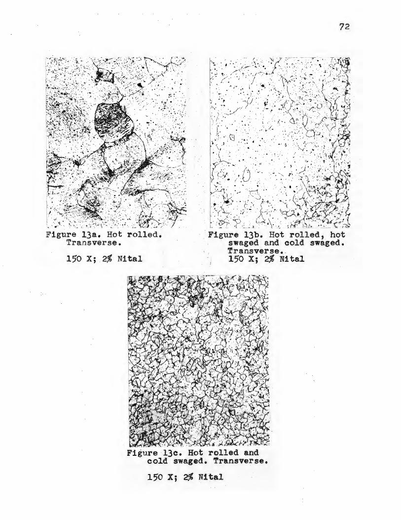
72
Figure 13a. Hot rolled. Transverse.
15'0 X; 2% Nital
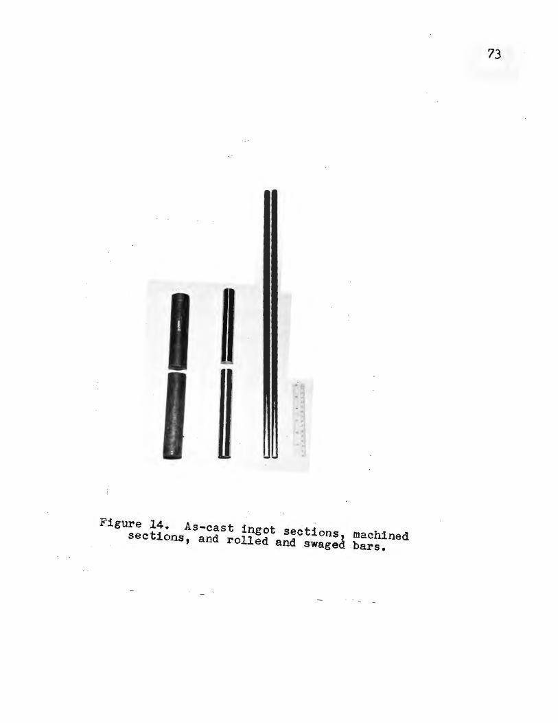
..
Figure 14. As-cast ingot sections, machined sections, and rolled and swaged bars.
73

74
4. Hot Twisting
The bars were hot twisted on the apparatus developed
at Globe Steel Tubes Company*and described previously. The
bars were all 22~24 inches in ·1ength to fit the chucks o~
the apparatus. The bars .as they appeared prior to the hot
twisting are shown in Figure-15a~
· The bars were twisted at 1750°F (954°c). This temper
ature is in the middle of the hot-short regio_n. Near this
temperature, hot shortness is mos.t' ~: pr~valent in ingot iron.
According to the theory, the extent of t_he ·solubility of
the molten iron sulfide in gamma-iron at this temperature is
insufficient to alleviate the hot-short condition.
The .bars were soaked for 20 minutes at the twisting
temperature to insure complete recrystallization. Ingot iron
is unlike carbon steel in its recrystallization behavior.
Cold-worked ingot iron will not recrystallize below_ the A3 temperature unless the extent of cold working has been 70
(41) per cent or more. Kenyon lists a number of references
dealing with the recrystallization behavior of ingot iron
and its stability to heat treatmen~-below the A3 temperature.
The general consensus of opinion is that, whi·le the impuri
ties in ingot iron offer more nuclei for recrystallization,
they also inhibit grain growth even more, with the net effect
being the same as if the impurities reduce the number of
recrystallization nuclei.
The bars are shown in Figure 15b as they appeared after
hot twisting. *Now the Babcock and Wilcox Company, Milwaukee, Wisconsin

7'5
Figure 15a. Bars prior to hot twisting.
Fi_gure 1'5b. Bars after hot twf~ting._

IX • . EXPERIMENTAL. RESULTS
lo Nominal Addi.tions to Heats
76
The heats and the nominal additions _are tabulated in
Table VIIo The percentages are calculated on the basis o~
the 11-pound · (4994 gram_s) charge of Armco iron punchings.
To heats 3, 4 and 5, ·_th~ rare earth metal addition
was ordinary mischmetal of the approximate composition:
Cerium Lanthanum Neodymium Other rare earths
50-55 per cent 22!""25 · per cent 17 per cent balance
The rare earth metal additions to ·heats 7, 8, 9, . 12,
13 and 14 were Lan-cer-amp No. 2 having the approximate
composition:
Cer'ium Lanthanum Iron Other rare earths
45-50 per cent . 30 per cent minimum ·5 per cent balance ·
The rare earth oxides which were added had the approx~
imate co.mposi tio_n:
· Cerium oxide, Ce02 . Lanthanum oxide, L~203 Neodymium oxide, Nd203 Praseodymium oxide,.Pr6011 Other rare earth oxides
48 per cent 24 per cent 17 per ceJ?.t 5 per cent balance
The logs of the heats made are given .in Appendi~ IIo
2o Results of Hot-Twist Test
The results of the hot-twist test at 1?50°F (954°C)
are given in T_able VIII. The numbers given precedlng ~tna :'.:
dashes represent the heat numbers. The numbers following the
dashes represent the section of the ingot from which th~ bar
· was ta~eno The 1' s . ·refer to_ the . bars which were taken from
. the upper halves of the ingots, and the 2' s those taken from ·

77
TABLE VII
NOMINAL ADDITI-ONS TO BEATS MADE
.Rare Earth Rare Earth Heat·· Aluminum Added Metal Added · Oxide Added Number Grams-Per Cent Grams-Per Cent Grams-Per.Cent
1A 75 1.5 1 100 2.0
.3 100 2.0 5.2 0.1
4 100 2.0 1;.o 0.3
5 100 2.0 25.1 0.5
7 100 2.0 5.3 0.1
8 100 2.0 15.3 0.3
9 100 2.0 25.0 o.; 10 100 2.0 ;.o 0.1 .
11 100 2.0 10.0 0.2
12 100 2.0 . 5'.1 ·0 .• 1· 10.0 0.2
·13 ·100 2.0 - 1;.1 0.3 10.0 . . 0.2
14 100 2.0 25.1_ 0.5 10.0 "Oo 2

TABLE VIII
NUMBER OF TWISTS TO FAILURE OF BARS
TWISTED AT 1750°F
Bar Number
1 A 1-1 1-2 ·3-1 3-2 4-1 4-2 ,-1 ,-2 7-1 7-2 8-1 8-2 9-1 9-2
10-1 10-2 11-1 11-2 12-1 12-2 13-1 13-2 14-1 14-2
Number of Twists to Failure
8 8
19 22
·41 13 10 21 32 35 27 4.8' 15' 5 9
2? ?6-25' 42 39 20 22 43 1, 23
?8

79
-~~e Jower }:lalveso Each heat .-is represented by two bars . .
.e;cept heat lA from which_ on~!- one. bar was madeo
3. Results of Chemical Anal:yses·
In_ T_able IX ~~e gi ve_n~ t}:le results of· the · chemical ·
analyses. Time did -~ot- permit .analyses of all _ of the sam~
ples .for alu~Jnum, oxygen, copper, lanthanum and cerium~- It·
is· felt that the analyses which · uerer::'.}!lei\foi:fmedffo.r-:/these .. •· .
elements -is. adequate for evaluati'on of the resultso_ The
analyses were perfo;med by two industrial laboratorieso·
4o Evaluation of Results
In Figure 15 is plotted_ the perc_entages of rare earth ·
metal added versus the number of twists -to .failure of the -. .
· bars at 1750°F (95'4°C) •. The lines connect points· which
represent bars which had the- higher number or twists for a ..
particular heato . There is some correlation for the Ool and.
O. 5 per cent rare earth additions.. The spread is_ greater for
the 0.3 per cent ad~itions.
The only data which could be found concerning. the
hot twisting of -ingot iron is given in Figure 16(36>-o· These
:bars Tiere ii'ot twisted below 2000°F, ioeo, the t'1isting was
above the hot-short region of ingot irono At 2000°.~, the
rimm~d :Lngot iron twisted ·only ab~ut 10 times before :fatlureo
The kil~ed i~~t iron, · howeve_r, tnis~ed· some 135 time:~ bef'o:EJ
lailureo- These data. ill:ustrate · the effeQt_ o:r _oxygen on ·
the hot- wbrkabi.lity ~ot: ingot ·iron abov~ ~h~. hot-shor~ .region.·:
and give so~e indication· of the number of tuis.ts that may be .. 0 expecte~ at. 1750 F.

80
TABLE IX
C:t)EMICAL ANALYSES
Heat Bar No. No. _g_ _§_ Al _Q_ · Cu La Ce
lA 0.0074 0.013* 0.018 0.05'4
l 1 0.042 0.014* 0.-032 . 2 0.020 0.016* 0.037 0.081
3 1 0.019 0.010* 2 0.012 0.010* 0.022
4 1 0.041 0.017 0.16 0.001 0.001 2 0.012 0.016 0.21 0.021 0.001 0.001 ., 1 0.015· 0.011 0.76 0.027 · 0.012 0.018 2 0.015 0.010 0.76 0.011 0.020
7 1 0.020 0.013* 0.015 2 0-.0087 0.012* 0.014 0.064
8 1 0.017 0.006* 2 0.0077 0.006* 0.063
9 1 0.11 0.025 0.14 0.050 0.008 0.012 2 0.016 0.020 0.25 0.052 0.009 0.014
10 1 0.014 0.020 0.78 . 0.001 0.001 2 0.012 0.020 0.78 0.022 0.00.1 0.002
11 1 0.013 0.022 1.07 0.001 0.001 2 0.020 0.022 0.96· 0.001 O.Obl
12 1 0.014 0.012* 2 0.034 0~014* . Q.004
13 1 0.015 0.004* 2 0.015 0.004* 0.016
14 1 0.019 0.010 1.02 0.023 . 0.035 2 0.020 0.010 1.05' 0.005 0.025. -0.035
s analysis by .source 2; other S analys~s by . source 1 . .

• s.. :::, .....
. or,f
ClS rx.. -0 . +l
fl) +,) . fl)
..... • E-4 '-4 . 0
s.. Q)
i .g
• ' ~I
70
60
,o
0
Legend-• No rare earths added Cl Lan-cer-amp No. 2 o Ordinary mischmetal · ALan-cer-amp No. 2 r o. 2 per cent rare earth oxides
c
------------------------------------0 ;: 0. l . 0·. 2 · 0. 3 0. 4 o., Per Cent · Rare Earth Metal Add-ed
' _Figure 15'. Number ·ot twists · to tailure versus . . ·.
. per cent rare earth metal added. - . . ·. .
..... ...... .
81

Legend-
3,0 o Ingot Iron, Killed (',.02C; : o.005:1n; C'.026s; C'. ·J09f; 0.02s1 .
o Ingot Iron, Rimmed 300 0.04C; o.26~n; 0.0245; 0.n04P;
t... 200 0
~
l ·i,o e ::, z
100
50
0 1900 2000 2100 2200 o- 2300
. Temperature, -r-2_400 ·
·.Figure· 16. Number of turns to failure of kil~ed and (36) . rimmed· ingot .irons versus te.mp~rat~e of twisting · · •
82

All of the .heats -made in this ·study .. we.re _.thoroughly . .
kill"ed. The bars to which no rare earths were added had ·
twists of 8, 8 and 19. This is approximately the number of
twists that the ingot iron withstood at 2000°F.· · or the 18
bars . to which.rare earth metal- had been added, 13 twisted
more than 20 times while 5 twisted less than 20 times. Some
improvement in workability is noted but the lack of correla
tion indicates that other variables are factors. ·· The bars to
which 0.5 per cent rare ~arth metal was added average less
twists (17.5) than those to which 0.1 per cent rare earth
metal was added (30.6 twist~).
No :·-conclusions cari" be drawn as to the relative effects
of ordinary mischmetal and Lan-cer-amp No. 2. For the 0.1 per
cent additions; the points are in fair agreement. ror the ·0.3
and 0.5 per cent additions, no trend appears.
Closer agreeme.nt occurs between the heats to which ..
only · Lan-cer-amp No. 2 was added., and . those heats to which
both Lan-cer-amp No. 2 and rare earth oxides were· added.. The
rare earths .apparently -have no significant effect in these
.heats. . The .rare earth oxide heats ·will be discussed· below.··
· I _n .Figure 17 is plotted the final percentages of' sul
fur versus the -number ·of : twists. The ·points are wi~ely scat
. tered with no apparent correlation~
The final· percentages of sulfur are plotted versus the .
percentages 'of. rare earth metal additions _ in Figure 180 There . . . .
appears to be a dif'f~rence 1~ the two sets of analyses .·per-
formed. :By plott~ng the sulfur· analyses £rom th~ two sources

0.040 ·
0.03,
r:.030
0.010
.o. 005'
()
0
Legenrl-·. e source 1
a source 2
• • •• •
• • • a
a a a o
D ·• • · ae • · a
a · a
·a . a
·10 20 30 40 Number of Twists to Failure
Figure 17.· Per cent .sulfur versus number of twists to failure.
84
•
.70

,.., · ··, r'1
0.010
a
Legend-
0
o Source 1 o Source · 2
r.1 0.2 0.3 0.4 . Per Cent. Rare Earth Metal Adderl
Figure 18~ Per cent sulfur versus . . . P~r cent rafe earth m,e-tal added.
es

separately, _·the two curves shown are. obtained; · There is."·a ./j. .
definite decrease in sulf~r contents with increasing rar~
·e~rth · metal additions o Source 1 reports the lowest sulfur ..
contents. f"or bars 5-2; 14--1 and -14-2, ·all 0.010· per cent su).-.
fur _cor~espon~ing to rare· ear~h metal additions of O·o 5 per ·
· cent-. Source· 2 reports the lowest sulfur contents for: bars
8-1 ·and 8-_2, ·both 0.0~6 per cent sulfur, and bars· 13-1 and .
13-2, both 0.004 per cent su~fur--ali four of these bars·
having had 0.3 per cent rare earth metal added. Source 2
d~d not analyze ·any samples to which o.,.per cent rare earth
·metal had been added.
J3amples from four· bars to which no rare earth metal
had been added were analyzed for sulfur by source 1 (bars
10-1, 10-2,-11~1 and 11-2). Samples from three bars to which
nq rare earth-metal had been added were ana:tyzed by source 2 .i
(bars ll,. 1.;.l and 1-2). The aver.age sulfur content of the··-·
four bars analyzed by source 1 was o.·~21. per _cent, and the
ayerage on the three ba.rs anaiyz.e<t by. source· 2 was 0.00143 p,er
cent. U-sing , these· values· as ave~age initial: sulfur contents·,.
the best· su;tfur drop from the anaiysis· or. sourc_e 1 is. 52 per
cent. (heats ·5 and·l4) ·and from source 2 the best drop is·
72 per c·ent (heat··.13) o
·Bar 9-1 was inadvertently. machined· with oil.' The ·:turn-·
ings we.re soaked for s·eve!al hours in CCl4 befo~e sub.nutting:
for analysis~ ·The sulfur content is 0.005 p~r-cent higher· 1~
bar 9-1 than in bar 9-2; as the higher. v~lue is belieyed·d~e
to· the oil, the sulfur ~aly"s·1s 6"n bar 9-1 is not usedo

87
The substantial ·sulfur drops noted are not accompanied · ·
by a significant incre~se ~n hot workabili~Yj i.e., a notable
decrease in hot shortness.
One of the factors ·contri_buti~g to this lack of cor
relation is seen in ·Figure 19· in which .percentage of oxygen
is plotted· versus the number of twists to failure. Althoug~
the points are somewh~t scattered, a· definite .trend appears.
Below 0.025· per cent oxygen, the percentage of oxygen appears
to have little effect on the number of twists. For the five
-bars.in which the oxygen contents exceeded 0.025 per cent,
tqe average ·number of twists was 12.
In Figure 20 is plotted the percentage of residual
aluminum vers-µs the number of twists .to failure. The plot
has .an inverse relationship to the plot of per cent oxygen . .
versus the number1
of twists, i.e., the higher tne residual
aluminum-content, the lower the oxygen _content as ·would be . .
expected. This is substantiated _i~ Figure 21 in _which per
cent oxygen i~ plotted ve~s~s pe~. cent · resid:11al aluminum.
It is interest~ng t~ note · 'that, although most of the_ :aiumi
num ·1.s in solid solution·, the b:i.gh_ -residual aluminum contents
do ·not, in the~selves, appear to have a detrimental effect
on the . hot workability; the! _do 'in -fact, appear to -. reduce .
the hot shortne.ss. The. near inverse re:Lationship bet~een . the
plots of number of twists versus o~rgen and aluminu~, respec-. .
tively, indicates that the apparent i~cr~as~i.i-n worka~ility
accompanying t~e hig~e.r residual· ·al~inum contents is most
probably due to the ·accompanying lower oxygen-·. contents--

.. ! . .-"'
0.070 ,,
~:- ·'
0-.066 /. ' , . . ,. · · ·'·
. . ; O.O?O ··-~. _. : ·. , o = . - -. • • • •. ·o·
; .. . ·. 0.0:1'({
0
_'. 0, . -, . . ~'
/. . . .
. .
. -o o ·.
0 . . •. . o .
0
o ·
Q ' .._ __ -.-..,__ ____________________ ~~---..------~---------~----( : { O. · lQ, .. · 20 ·. · 30 40 · · · .50 60 · 70. · 80
· • . Numb~r·-: :--,1f Tw1 s ts to .Failure
Figure . :i9o. Per cent · oxygen versus : ··.·number of twists ~o failureo ·
,.,
.. ·-. : !_
88

e ·E -rt e :;s·· ,;.' .
0
. 0 O ·
0
0
N .< . 0:60 .µ .C:
. G) 0
~ .Cl) ~ . ·
0.3':o- .
0 , .. · . .. ~: ________ ......_ ___ ~~---------~~------~........1.__--~~~------"--~---J
J · <o .. .10 <. ?O · ··r. · .· 30 .40 .· 50 . 60 . 'JO. . . . ·. 80 . : .. : : . Number of· Twists to Failure · .
~.:l.gure· 20:. · .:: Per cent re.sidual ·:. aluminum·· versus · .. . 'number or.. twists .. to:;.failure. :' .. ·. · .... · .< :·
... ..~· /

0 _~08_.Q ·
c: 0, . _ bOo.,o;o >. . ' x ·· - . , -0 .. .
·.µ 0.040 ·C
Cl) . •. ti . ~:o~OJQ Cl)
~ -
. { ·;0 •. 020.
0
0
9. 20 ··- o.40 0.60 0.80 -;· ' . : Pe-r ce·nt Residual Aluminum
F:l.g~r,e._ 2l·o -- Pet: cep.~ : oxygen·jr~_tsus per :.,cent residua1~:;aluminlll11~ . .
90 -
0 0
1.00

91
. . oxygen·heing a well~known ·cause or· hot ·shortness.
Sample~. from only ~our bars were analyzed for _copper
a-s the punchings used for all of the heats · were , from· the ·
same batch. The copper contents are _just b~lo~--o"ne is · the
same ·as.--the. approx:tma.tely 0.08 ·per cent . which Nahl (33) had
found was the maximum copper which c_ould be present wi tho-µt
affecting the hot work~bili ty of plain carhon steel . _at
1050°c. The percentages are cons'iderably lower than the max
imum of 0.15 per. cent copper specified by Armco for their
ingot iron.
The iron-cerium dia~ram is shown in Figure 22. The
solubil~ty limit of.cerium in alpha- and gamma-iron ·in_ the
temperature. rang.e 815'-1015°c (1499-1859°F) lies close ·fro
0.4 weight per ceD.t(iS). · The solubility is believed to be
lower . at lower temperatures. As _~ong as sulfur and oxygen
are available in molten iron containing cerium (a~d.lantha
num), th~ cerium :would be expec_ted tq contim,1.e to react
~t11 ·1t w~~-depleted.
·The cerium and -lanthanum analyses indicate . that ··appre~
ciable residual_ amounts may be present for only the Oo5 per . . . . .
cent" .rar"e earth metal additions. I°t. would have· been. desira- . . .
. . . . .
ble· to have · had cerium and lanthanum ·analyses performeq for . · ' .
all of · the bars but this · was no~ po.ssible. · Also, ~he analyses .
given do not differentiat_e between rare· earth compounds and _.
residual rare earth metal in solid solution • . . .
The analyses _for heats 5, 9 and· 14--all of which had . .
~.5 per cent rar~ earth metal. added--sho~ appreqiable cerium
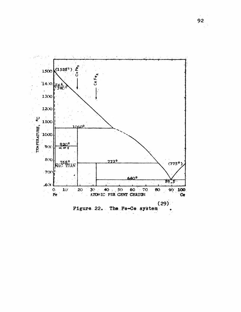
-. -_ tn
1500 (1528. 0 } it -_ .
. . . ~
1300' · -I
- I , 1200
I "U I
· 0 - - 1100 I
. . () . . · .. l 1--
. .... , I o . -r ·100l 1------.~~~---~ ........................ < .
- ~ -
i::. . 0 ~ _ l)(X'1 _ . __ _, - .,, (&:: . ----· H
8('() -q;~- -_.-..,-_______ o _______ ~
~t, mAN
...,6(). ':......., ____ ,...._. ____ ........_ ____ ...._ _______ ....____.. __ __
Q ; 10· .20 - 3(~ . · - -.40 :- so 60 ' .. ·70 '80 .. 9<)'' -100 ):'e . .\'lUMIC . PBR' CJ!NT CEJlltf,t . .. ~ . ·ee .
(29)·.'· -F_igure. 22 • . The,. Fe-.;.ce -syste~ · ~
92

93
and lanthanum contents. Heat 4, to which· 0.3 per '!ent rare.
earth metal was added, h~s a very low cerium and lanthanum
content. Analyses of heats 8 ~nd 13, to which 0,3 per cent
rare earth metal ~as also added, would have b~en desirable~ ..
The sulfur contents are low for thes·e heats. If the cerium
and lanthanum contents were also l _ow, the two . minute holding
interval between the r~re earth metal additions and pouring
was sufficient for almost all of the rare earths.to react;
the converse would, of course, be true if the appreciable
cerium_ and lanthanum contents remained. For the 0.5 per -cent
rare earth metal additions, an additional minute or so of
holding_interval would have been desirable for more complete
reaction.
Worthy .of mention ·is the possibility that these
cerium and lanthanum contents may have an effect on hot ~
wor~ability, perhaps by reducing the ductility of the gamma
iron as a result of the solid solubility._ This could conceiv
ably be the_ reason that the heats to which 0.5 per ce~t rare
earth metal was added · averaged ·less t _~ists than those t _"o which
only 0.1 per cent rare earth metal was added.
To heats 10 and 11 were added 0.1 and· 0.2 per cent
rare earth oxid"es, respectively. The residual cerium ·and lan
thanum contents are small. ·The method of addition _is a factor.
The oxides were .wrapped in paper and stirred into the · melt
with a welding -rod. The oxides eit~er _did not get into the
melt, or they immediately floated back to the slag phase. One
very unusual result did appear in the hot-twist data on these

94
two he·ats. ·. Bar 10-2 (O.l per · cent oxide .·addition) twisted
76 ·. time.s whicl.1. is almo~t ·_twice the highest number o:f. twists
of any or the ·bars. This result can not be explained by t}:le
chemical analysis~ Bar 1(?-1, from t}?.e same heat, twisted
·onl.Y · 27 time~.··· .. The average o:f the other three bars ~f:roqi
these two heats was 31 t\vists. Thi$ is considerabl:y higher·
· than the average of the heats to which .rio ra.re . earths were · . ·. .
added (12 twists)'. Perhaps even ·small quanti t'ies or ~he
oxides serve as ~ucleating agents resulting in a finer
grained gamma-ir~n at the twisting temperature.
The r ·are earth oxide_s in heats 12, .13 and 14, how~ver·,
appear -~o have no.significant ef:fect when compared to heats . .
?, 8 and · 9 -which are o:f · t~e same nominal composition except:
:for the rare earth oxide additions. Further study . would be
neces~aiy before conclusions could: be drawn on th~ effects bf I
the rare · ee.rth oxides. Compacting the oxides into briquette_s
:for ·the . a_ddi tions : may result in. m~re .cons_i _stent resu~·ts.
Th~ ·-~_arbon · contents are in · the range .. of O ~ 015'· per . cent
given by. Armco . as a typical -8:Il~lisis ~f .·their ingot iro:n •
. Some of tpe . bars showed some carb~n pick-up :from the ·ingot
mold but ' no correlation appeared betwe~n hot workability
or sulfur drops· and - carbon corite.nts~. · Bar 9-1 appears to have : . .
been contaminated with carbo~ ·by · the machining· oil ._and(or .the
CCl4 solvento
95
2• Sulfur Printing
Sulfur printing affords a convenient means of detect
ing and permanent·ly recording the distribution of sulfur in
iron and steel· •
. ·The method consists es.sentially of placing in inti
mate contact on a prepared metal surface, photographic
bromide paper which has been previously soaked in a dilute
solution of· sulfuric acid in water.
The reaction of the sulfuric acid with the · sulfide
regions of the iron or steel produces hydrogen sulfide gas,
wnich reacts with the silver bromide in the paper emulsion,
forming a characteristic. brown to gray-black deposit or
silver sulfid~. The sulfur printing technique is described
in detail in Appendix IV.
The bottom transverse sections which were· sulfur
printed were cut approximately one-half inch from the ingot
bottoms. The top transverse sec~ions of ingots 1, 11, 12 and
13 were cut just below the pipes, while the other top sec
tions were taken one-half to one inch .below the pipes. The
sulfur prints of these top and bottom transverse sections or
the ingots are _shown in Figures 23 through 30 •
. The sulfur prints of the bottom transverse sections
of the ingots show very little sulfide segregation. When ·
sulfide regions do appear, they are .toward the ingot edges •.
This is particularly evident in the bottoms of . ingots 12, 13
and 14 (Figures 28b, 29b and 3ob; respectively). The appear
ance of sulfides in the first parts of the ingots to solidify

Figure 23a. In.got No. 1,top. As cast. Transverse .
2% H2so4 , 3 minutes
Figure 24a. Ingot No. 5, top. As cas.t. Transverse.
, -
Figure 23b. Ingot No. 1, bottom. As cast. Tra.nsverse .
... ·. ~,. . '\,.
. ., •. \
' ' { .. ~ .
, I , . ·• .. .
.· · . . ~--- - ~ .. ----. '
... .,.·
Figure 24b. Ingot No. 5, bottom. As cast. Transverse.
96

'.;-:<<,~ <~;:\ · . t ~-~ _ .. , ~ :~ .
\ ,, •u1 ~ • •
' ·., .... "':- t. . . ·L. : .. :~:~·" .
Figure 25a . Ingot No . 7, top. As cast. Transverse.
Figure 26a. Ingot No. 9, top. · As cast. Transverse .
Figure 25b. Ingot No. 7, bottom. As cast. Transverse.
Figure 26b. Ingot No. 9, bottom. As cast. Transverse.
97

Figure 27a. Ingot No. 11; top. As cast. Transve~se.
Figure 28a. Ingot No. 12, top. As ca.st. Transverse.
Figur~ 27b. Ingot No. 11, bottom. As cast~ Transver$e.
Figure 28b. Ingot No. 12, . · bottom. As ·ca.st. Transverse.
· ,
2% H2so4 , 3 ~inutes
98
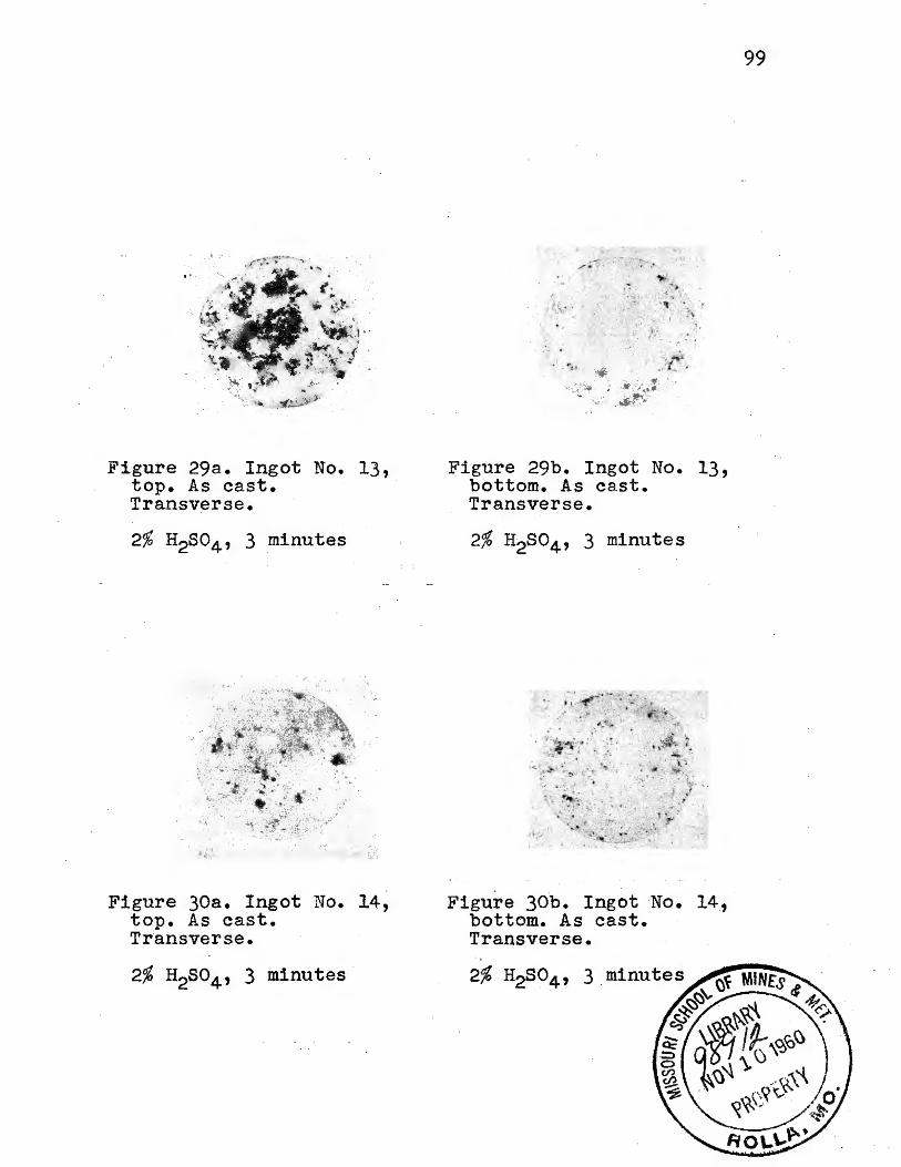
Figure 29a. Ingot No. 13, top. As cast. Transverse.
Figure 3oa. Ingot No. 14, top. As cast. Transverse.
-,. !>•
. . :·. .... : '(, .-· ... .. ·-_, . . ,.li--~·-- .
Figure 29b. Ingot No. 13, bottom. As ca.st. Transverse.
Figure 30b. Ingot No. 14, bottom. As cast. Transverse.
99

100
indicate that these sulfide inclusions are ·refractory and
were entrapped toward the outsides of the . ingots where
solidification was most rapid. The relative lack of sulfides
toward the centers of the ingots indicates that solidifica
tion was sufficiently slow for the sulfides to ·c·oalesce ·and
float upward during solidification. The sulfides are more
numerous, darker in color, and more sharply outlined in the
prints of the ingots to which rare earth metal was added.
The prints of ingots 5, 7 and 9, Figure-s 24b, 25b and 2~b,
show less of the sharply outlined sulfides while ingots 1 and
11 (Figures 23b and 27b), to which no rare earth metal was
added, show none of the sharply outlined, dark sulfides. T_he
sulfide regions of ingots 1 and 11 have diffuse outlines.
The sulfur prints of the transverse sections of the
ingot tops appear to the right of the corresponding bottom
sections. The prints of the tops of ingots 5' and 7 (Figures
24a and 25a) show sulfides only near the edges. The tops of
ingots 9, 12, 13 and 14 show su~fides throughout the cross
sections. The tops of ingots 1 and 11, to which no rare earth
metal was added, show sulfide segregation predominantly in
the pipe region. The sulfides in the tops of ingots_!. and
11, as in the corresponding bottom sections, appear in
patches which do not have the reguiar outlines or dark color.
of the sulf-ides in the ingots to which rare earth metal was
added.
The difference in appearance of the sulfides in the
ingots to which rare earth metal was added indicates that

101
these sulfides are most· probably rare earth ·sulfides. The
much more numerous occurrence of these sulfides in the ingot
tops shous that they floated upward during solidification ot .
the ingotso The irregular sulfide regions in the tops of·
ingots -1 and 11 ( no rare earth metal) are most · probably due
to sulfur enrichment of the last metal to solidifyo This
would mean that these regions are composed chiefly of iron
sulfides or iron oxi-sulfideso The tops of ingots 9, 12 and
13, to which rare earth metal was added, . show both· types of
. sulfideso
To determine the relative cabling rates in the ingot
tops and bottoms, the sections which had been sulfur printe~
were macroetched for grain ·structureo The macrostructures of
the top and bottom sections of ingots 1, 11 and 13, which .
are typical, are shown in Figures· 31, 32 and 33, ·res_pective-
lYo In the ingot bottoms, the cooling rate was slow enough
for large, columnar grains to ·rormo In.the ingot . tops, the
cooling rate was considerably mor_e rapid as evidenced by the
lack of columnar grains.
· .. Microstructures sho'\1ing the relative grain sizes In
the top and bottom sections (same sections sulfur ·printed)
are shown in Figures 34a, 3~b and 34Co The grains are large
in the ingot bottomso The large, columnar grains are met to
uard the ingot centers by large, equi-axed grainso In the
ingot tops, the grains are much smaller indicflting a faster
cooling rateo The very large grafns in the ingot bottoms in
dicate that the cooling rate was sufficiently slou for

102
Figure 31. Ingot 1, macroetched sections. Ingot top, above; bottom, below. 10% Nital, 2 minutes
Figure 32. Ingot 11, macroetched sections. Ingot toP-, above; bottom, below. 10% Nital, 2 minutes
Figure 33. Ingot 13, macroetched sections. Ingot top, above; bottom, below. 10% Nital, 2 minutes ·
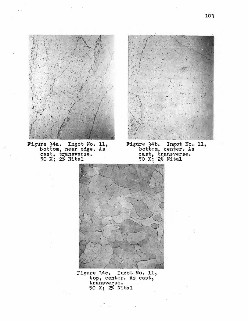
Figure 34a •. Ingot No. bottom, near edge. cast, transverse. 50 X; 2% Nital
11, As
Figure 34b. Ingot No. bottom, cen~er. As cast, transverse. 50 X; 2% Nital
Figure 34c. Ingot No. 11, top, ceriter. As cast,· transverse. 50 X; 2%, Nital
103
·11 '

104
refractory compounds such as rare earth sulfides to float
upward during solidification of the ingots. This would ex-_
·plain the much more numerous sulfide occurrence near the top-s
of the ingots to which r~re earth metal was added.
·If the sulfides in the rare-earth metal ingots.are
rare earth sulfides, then the slag-scum beads should show ·
the same type of sulfides in the sla.g removed· after the rare
earth metal additions were made •. The ·slag-scum beads from
ingots 1, 5 and 14 were cut in half, polished, and sulfur
printed. These prints are shown in Figures 35, 36 and 37.
The beads were formed in layers by the slagging during and
after the aluminum additions, and after the rare earth addi
tions. The sulfur print of . the slag bead from ingot 1, to
which no rare earths were added, shows none of the dark,
sharply outlined ·sulfides.· The prints of ingots ·5 and 14·,
however, to which 0.5 per cent rare earth metal was added, ' . . .
show a definite accumulation of'. sulfid.es· in the outer. layer-
the layer which was slagged . off ~fter the rare earth.metal
additions. These sulfides are the· a·ark, ~harply· outlined
type· •.
From these evidences and the sulfur· drops that·.
occurred, it is concluded t~at the rare earth metal addi
tions resulted ·1n the formation of rare· earth sulfides; ·
these sulfides being refractory, many floated to the slag
phase in the two-minute holding intervals. Most of these·sul
fides were removed in the subsequent slagging; those which
were not were either entrapped towa3::d. the outsides of the
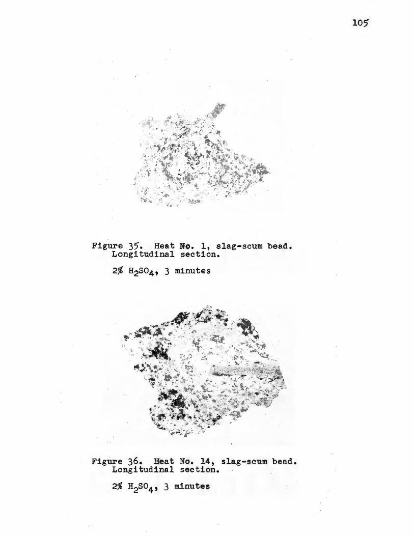
10,
,. . ': .. _ .. ~··.
J .• : ~. ~~- •
:; ._,
--~ ·.
,\ , .... . ·. t:: ~ .. <.
Figure 35. Heat No. 1, slag-scum bead. Longitudinal section.
2% H2S04, 3 minutes
Figure 36. Heat No. 14, slag-scum bead. Longitudinal section.
2% H2so4 , 3 minutes
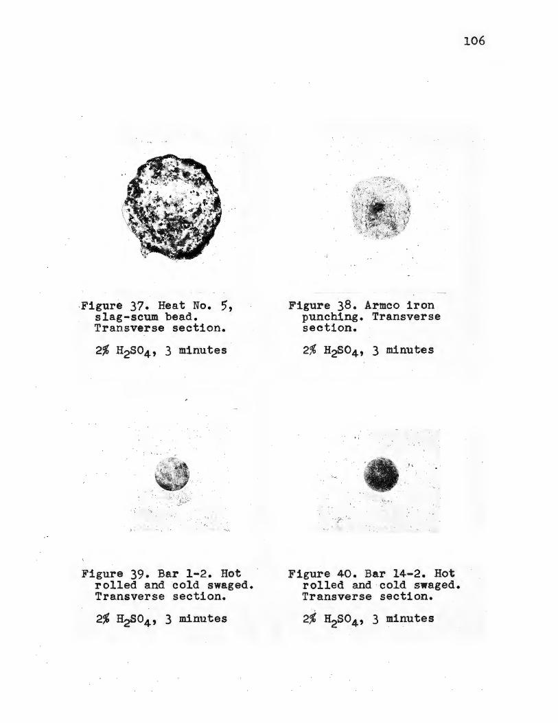
·Figure 37. Heat No. ,, slag-scum be·aa. Transverse section.
'- ~. •.
Figure 39. Bar 1-2. Hot rolled and cold swaged. Transverse section.
Figure 38. Armco iron punching. Transverse section.
Figure 40. Bar 14-2. Hot rolled and cold swaged. Transverse section.
2% H2so4 , 3 minutes
106

107
ingots during solidification, or floated up · toward the ingot
tops. The relative. lack of sulfides in ingots 5 and 7
indicate that mos·t of the rare earth sulfides were removed
in the slagging.
·Figure 38 shows a sulr'ur print of an Armco iron
punching, and Figures 39 and 40 prints of bars 1-2 and 14-2.
The sulfide distribution is quite different in the rolled
bars thari in the cast ingots. Sulfide regions are broken ~p
and redistributed in the hot working of .iron and steel,
illustrating the necessity of using . cast structures in the
~tudy of desulfurization mechanisms.
6. Study of Inclusions
In the. sttidy of inclusions, use was made of projection
of the ·microstructures onto the ground glass plate · of the
·metallograph, special etching, and polarized light illumina- ·
tion. Table X lists the colors of some.compounds w~ich may
be expected to appear as inclusions iri the various ingots.
The true colors of non-metallic ~nclusions will frequently
show very ~learly in polarized light while true colors rarely
appear in white.light. The polishing and etching technique is
described in Appendix· V.
· Figure 4la shows the. _unetched microstructure of an
Armco ~ron punching at 150 X. The microstruc-ture shows a·num
ber of relatively large inclusions •. These inclusions are
mostly rounded and appear medium gray .in.· color. They ~re· rela
tively unattacked by a two per c·ent nital etch (Figure 4lb)
and exhibit definite outlines upon ~t~hing. When projected
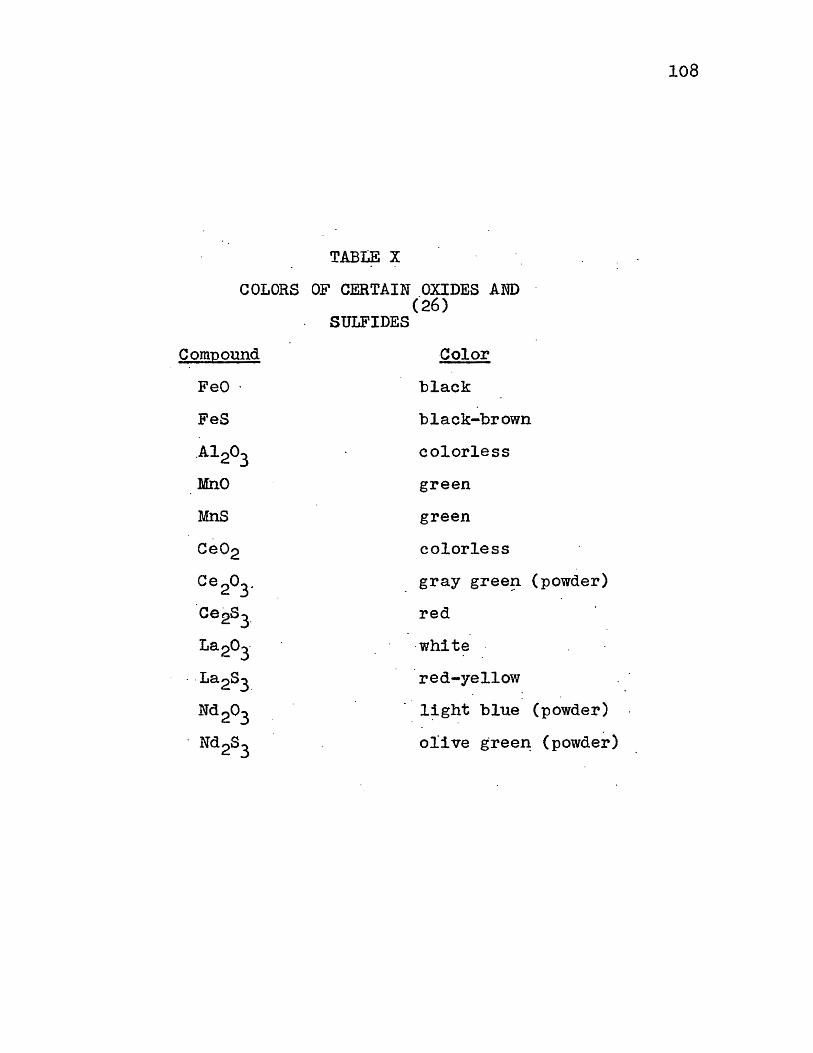
TABLE X
COLORS OF CERTAIN OXIDES AND (26)
SULFIDES
COfil:[?OUild Color
FeO · black
FeS black-brown
.Al2o3 colorless
MnO green
MnS green
Ce02 colorless
Ce 2o3. gray gree!l
Ce2SJ red
La2o3. -white
· -La2s3_ red-yellow
Nd2o3 l~ght blue
· Nd2s3 olive greeD;
108
(powder)
(powder)
(powder)

.. ..
Armco iro~ punching. Transverse _ •
. 150 X; Unetched
·.· ..•. · . o· -
. - · ;. . ' -~ -
. ·, .... . •' ' .
,.. ·, . . .. . ,: .
Figure 4lbo Armco iron punching. Transverse.
150 JC; _ 2% Nital
109

110
onto the ground glass plate of the metallograph with the
unfiltered carbon-arc light source, these large inclusions
appeared · gray. Irf polarized light, they were black. Iron · : .·
oxide (wustite) inclusions are relatively unattacked b_y nital
etchi'ng, appear gray when projecte.d onto th~ ground glass
plate, and.black in ~olari~ed lighto These evidences, toge
ther with the fact that commercial ingot iron conta~ns up to
0.10 per cent .~xygen, identifies . these inclusions as being .. ..
wusti~e or wustite rich. Many of the smaller inclusions
appear bright white in p~larized light. Their small size and
appearance· in polarized light indicate that - many of these
small inclusions are Al2o3 resulting from the ladle deoxida
tion with aluminum. pome of these smaller inclusions are
black in polarized light indicating that some of them are .. .
also wustite. Some are green in polarized light indicating
that these are MnO and Tu1nS. Iro.~ sulfi~e inclusion~·, alt.hough
some were_ undoubtedly present, were not identified. ·
In Figures 42 through ·53- are shown the unetched mi
crostructures of ingots 1, 5, 9, ·11, 13 . and 14 at 150 X. The
photom:i.crographs show the inclusion contents at both the
ingot tops and bottoms. The ingot sections shown are· in the
as-cast condition. Most of the inclusions· are small in com-I
parison to many which appear in the Armco fron punching. The
photomicrographs were in each instance .or the same surfaces
as the sulfur prints discussed in the preceeding section.
The microstructures of the tops of ingots 1, 11 and
13 were taken from sections which were cut just below the

,,.,,.·. . .. t ·· . :
....... ; . . -,:., .... :.. ~ '·:: .- - ' . ... · .
. ·.~ .; .. ,. . . ~ ·:·.. ~.:
·!: -.
Figure 42. Ingot No. 1, top. As cast. Transverse. _ 150 X; Unetched
... ,.
•
. . , . ~ : ~ : . .. (. ,
~ . . . .. •.
Figure 44. Ingot No. 5, top. As cast. Transverse. 150 X; Unetched
• ' ·-- - . ____ __ __,,_. ___ _ .--... · -~ ---- ~ ... -·---- --- -- - ---·- -·--
Figure 43. Ingot No. 1, bottom. As cast. Transverse. 150 X; Unetched
. , ;
_..,. ·
'. ..
Figure 45. Ingot No. 5, bottom. As cast. Transverse. 150 X; Unetched
111
_ . · · 1
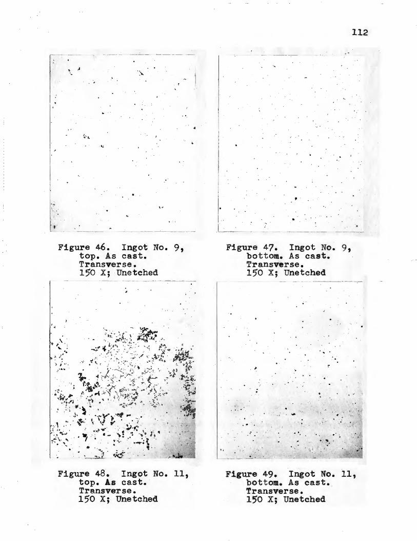
' . A
-~ . .
. .
Figure 46. Ingot No. 9, top. As cast. Transverse. 150 X; ·Unetched
Figure 48. Ingot No. 11, top. As cast. · Transverse. 15'0 X; Unetched
I
, .
•
Figure 47. Ingot No. 9, bottom. As cast. Transverse. 15'0 X; Unetched
... . > !"'
.; ·
:
? • . .. , . .. ;
. . .
112
. .
Figure 49. Ingot No. 11, bottom. As cast. Transverse. 150 X; Unetched
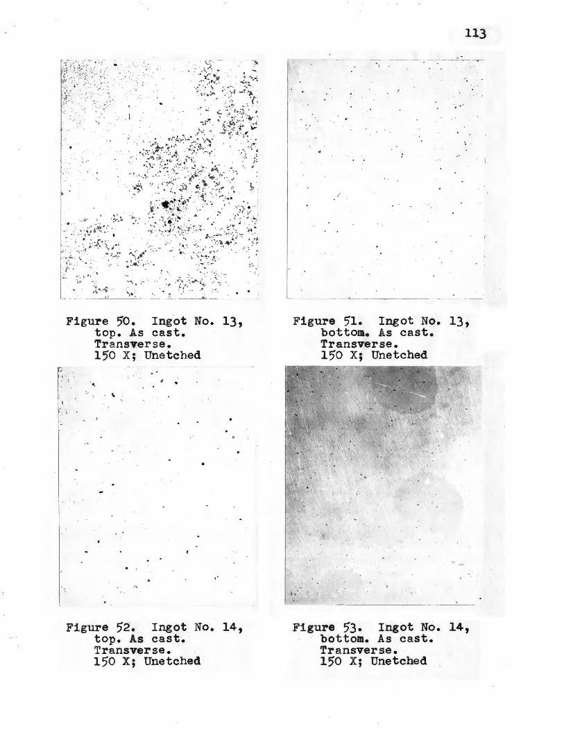
• · . .. · .. . · ,· . . ·.
· .·· .. :·' .. . . . · .: ·: . . . · .... _·:·
. I·
•t · .... · ;
· .:.t·;;_r..· . .... ;. (' . '
'\ I, : ' · ... .. -~ , ·.;:..~~!/.·.~_~.:_;.- ·\··.-\....- .
:i~.~· •' - T
- -- - r ... _ _ _ __ ·, .. , ~ :~ •• ~· - - ~ . ... -·--- - ~ - -'-
Figure 50. Ingot No. 13, top. As cast. Transverse. 150 X; Unetched
. •. . ~
Figure 52. Ingot No. 14, top. As cast. Transverse. 150 X; Unetched
, ,j
:·? ( .~ .,
113
Figure ;1. Ingot No. 13, bottom. As cast. Transverse. 150 X; Unetched
~--------~ -·----- -
Figure 53. Ingot No. 14, bottom. As cast. Transverse. 150 X; Unetched
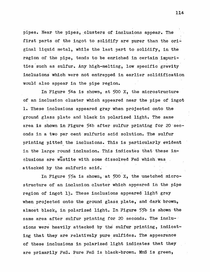
114
pipes. Near the pipes, ·clusters of -inclusions appear. The
first parts of the ingot to ~olidify are purer than the ori~
ginal liquid metal, while the last part to solidify, in the ·
region of the pipe, tends to be enriched in certain i~puri
ties'such as sulfur. Any high-melting, low specific gravity
inclusions which wer~ not entrapped in earlier solidification
would also appear fn the pipe region.
In Figure 54a is shown, at 500 x, the microstructure
of an inclusion cluster which appeared near the pipe of ingot
1. These inclusions appeared gray when projected onto the
·ground glass plate and black in polarized light. The same
area is shown in Figure 54b after sulfur printing for 2o·sec
onds in a two p·er cent · sulfuric acid solution. The sulfur
printing pitted the inclusions. This is particularly evident
in the large round inclusion. This indicates that·these in-
-clusions are wustite with some dissolv~d FeS which was
attacked ~y the sulfuric a~id~
In Figure 55a is shown, ·at 500 x, the unetched micro
structure of an inclusion cluster which appeared in the pipe
region of ingot 13. These inclusions appeared light gray
when projected onto the ground glass_ plate,· and dark brown,
almost qlack, in polarized light. In Figure 55b is shown-the
same area after sulfur printing for 20 seconds. The· inclu- :
sions were heavily attacked by the sulfur printing, indicat
ing that they are _relatively pure sulfides. The appearance
bf these inclusions in polarized light indic~tes that they
are primarily FeS. Pure FeS is black-brown. MnS is green,

' ··-4 .
•
o. ·, J.;,· ..
_, .. • .. -
Figure 54a. Ingot No. 1, top. As cast. Transverse section.
5'00 X; Unetched
. . -:- • . . .. . -. ~· -~~
• ..... , ..I. . 0 • • '->.\ ,7'" . ·.
·.· ·o · ,. -~ . . Ot
, ··, ..... ~ . . ' . .
. ''!
. • • r ·
' .
•
,, . -· .. . . t ~ .
Figure 54b. Ingot No. 1, top (same area as above) . As cast. Transverse section.
115

r-
I
1 ..
Figure 55a. Ingot No $ 13, top. As cast. Transverse section.
500 X; Unetched
·1 . , : I .
•
Figure 55b. Ingot No. 13, top (same area as above). As cast. Transverse section.
500 X; 2% H2S04 , 20 seconds
116
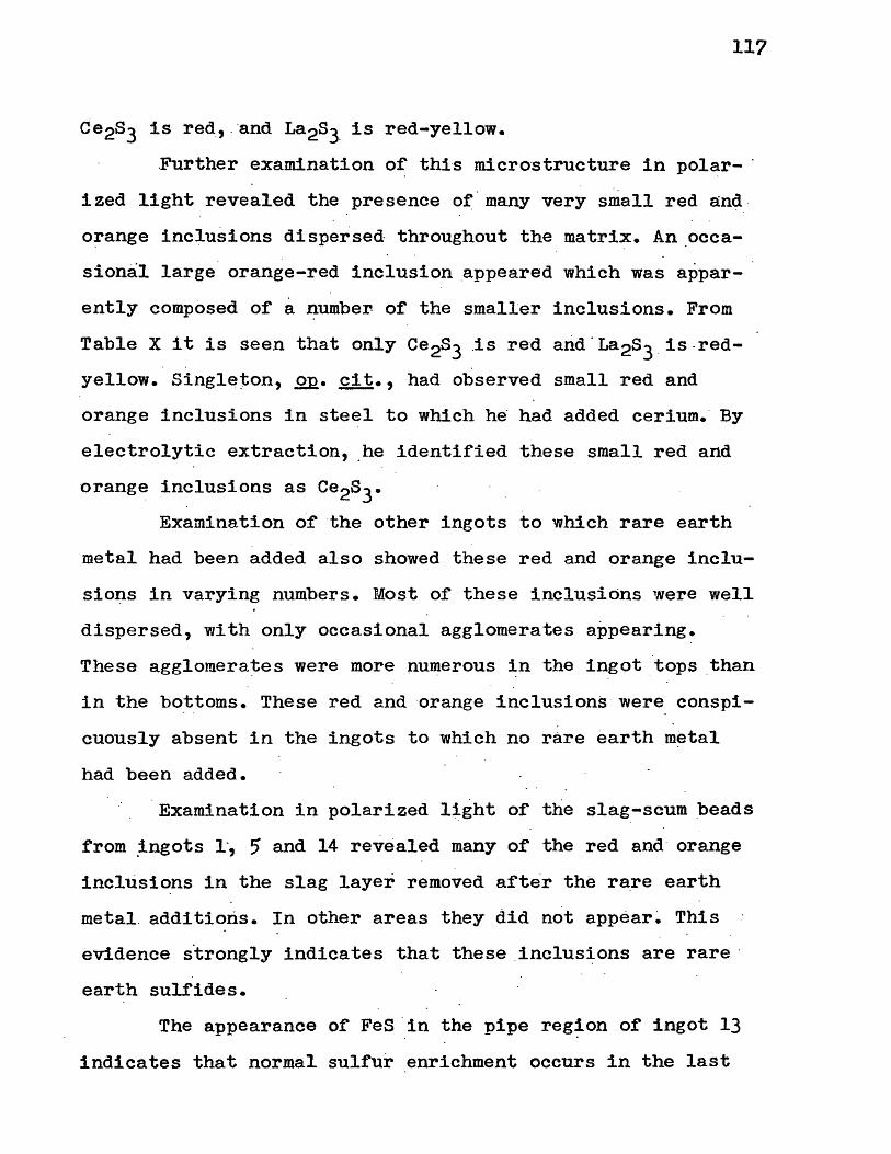
11?
Ce2s3 is red_, . ·and La2S3. is red-yellow •
. Further examination of this micro-structure in polar- ·
ized light revealed the presence of · many very small red and_
orange inclusions dispersed throughout the matrix. An occa
sional large orange-red inclusion _appeared which was appar
ently composed of a ~umber of the smaller inclusions. From
Table X it is seen that only Ce2s3 .is red arid.La2s3 _1s.red
yellow. Single~on, .QR• cit., had observed small red and
orange inclusions in steel to which he had added cerium. By
electrolytic extraction, .he identified these small red and
orange inclusions as Ce2s3•
Examination of the other ingots to which rare earth
metal had been added also showed these red and orange inclu-
sions in varying numbers. Most of these inclusions were well
dispersed, with only occasional agglomerates appearing.
These agglomerates were more numerous ~n the ingot _tops than
in the bottoms. These red and ·orange inclusions were conspi
cuously absent in the ingots to which no rare earth metal
had been added.
Examination in polarized ltght of the slag-scum beads
:from .ingots 1·, 5 and 14 revealed many of the red and· orange
inclusions in the slag layer removed after the rare earth
metal. additions. In other areas they did not appear~ This
evidence strongly indicates that these _inclusions are rare ·
earth sulfides.
The appearance of FeS ·in the pipe region of ingot 13
indicates that normal sulfur enrichment occurs in the last

118
metal to solidify involving the uncombined sulfur • .
The majority of the small dispersed inclusions shown·
in the other microstructures appear bright white in polar~ _·
ized light. ·A12o3 is colorless and appears white in P!='lar
ized· light. In view of the aluminum deoxidation, most ·or
these numerous white inclusions are most probably Al2o3 •·
There appeared in all of the ingots, · small dispersed
bright green ~nclusions. ce2o3 is gray green and Nd2s3 is
olive green. The numerous occurrence,· however, of thes.e .- · ,'
green inclusions in .the ingots to which no rare earths were
· added strongly indicates that they are MnO and MnS which
are both green. Armco · Steel Corporation gives, as a - typical
analysis of· their ingot iron, a manganese content of 0.028
per_ cent.
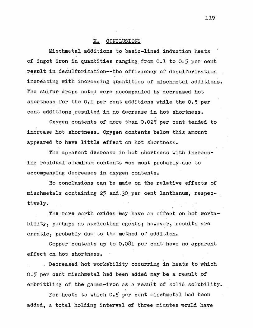
119
~- CONCLUSIONS
Mischmstal additions to basic-lined induction heats
of ingot iron in quantities ranging from 0.1 to Oo5 per cerit
result in desulfurization--the efficiency of desulfuri~ation
increasing with increasing quantities of mischmetal additions.
The sulfur drops note~ were accompanied by decreased hot
shortness for the 0.1 per cent additions while the Oo5 per
cent additions.resulted in no decrease in hot shortness.
Oxygen contents of more than 0.025 per cent tended to
increase hot shortness. O~ygen contents below this amount
appeared to have little effect on hot shortness.
The apparent decrease in hot shortness wi~h increas
ing residual· aluminum contents was most probably . due to
accompanying decreases in oxygen contents.
No conclusions can be made on the re la.ti ve effects of
mischmetals containing 25 and .30. per cent lanthanum, respec
tively.
The rare earth oxides may have an effect on hot worka
bility, perhaps as nucleating agents; however, results are
erra.tic, probably due to the method of addition.
Copper · contents up to 0.081 per cent have no apparent
effect on hot shortness.
Decreased .hot workability occurring in heats to which
Oo5 per cent mischmetal had been added may 'be a result of
embrittling of the _gamma-iron as· a result of solid solubility.
For heats to which Oo5 per cent misch~etal had been
added, a total holding interval of three minutes would have

resulted in more comple~e reaction of the mischmetal with
accompanying lower residual r~re earth contents.
120
From a study of inclusions aided by sulfur printing; -·
the reaction.·inechanism appears· to be, _that in the absence of
excessive oxygen, the rare earth m~tals reac.t with sulr"ur in
the molten .metal. The rare earth sulfides formed, being re
fractory and having .densities lesser than that of iron,
float upward t :c;, the slag phase ·where they may be removed.
If left for sufficient time in an oxidizing slag, the rare
earth sulfides will be o~idized with the sulfur revert~ng to
the melt. If the ingot cooling rate is sufficiently slow, the
remaining rare_ earth sulfides tend to coalesce and floa.t up
ward during ·solidification. The sulfides which do not have
sufficient time to coalesce appear as fine inclu.sions in the
matrix. In· polarized li_ght, these rare earth sulfides appear
red or orange.

121
SUGGESTIONS.FOR .. FURTHIDR STUDY
Although desulfurization occurred in heats. melted
in ~ir, heats . melted in neutral ~!].d reducihg atmosphere·s : _.
would also ··be of interest. Heats· could also be studied in . . .
which mischmetal· is added before deoxidati·.on is carrfed
out. Vacuum melting would enable further study on the
effects of oxygen · and other ·occluded gases·.
The e~fect of copper on hot shortness in ingot iron
could be studied--both with and without rare earth additions4
Effects of rare earth oxides in ingot iron could be
stuqied by adding the oxides as briquettes.-
The holding times between rare earth metal additions
and pouring could be studied further, particularly for
additions in excess of O. 3 pe~ .. cent.
Electrolytic extraction of ·inclusions ·would enable
their identification.
Pure cerium and lanthanum could be added to·. separate
heats for·purposes. of comparison. . .
ror studying reactj_on me.chanisms., use could be made
of-- rad~oactive isotopes. Sulfur· ·3, (half~life _37.i days,
beta ·decay,. ·O. 167 Mev) could be used .. to .study sulfur reac
tion mechanisms in conjunction with auto-radiography. Radio
acti.ve isotopes of ·cer~um may also be useci--perhap·s for
· studying ·rare earth-oxygen re·action mechanisms. Cerium 139
has a half life of 140 days," ceri~· 141 .a half-life of 33
days,. and cerium .144 a ha1r..:.11:re o:r 282 days •.

APPENDIX l
High-Frequency Induction Melting
122

123
All of the heats were made in a 17-pOund, tilting
type, Ajax-Northrup induction fm~nace. A charge of _11
pounds of Armco iron punchings was _used for each heat. Addi~
tions and slagging were accomplished by use of low-carbon
steel welding rods. The high-freq~ency power source was- a
20-kilowattAjax-Northrup, hydrogen-type, mercury spark-gap
converter. Such units are described in a number of referen
c_es. The advantages of induction heating are the speed at
which heats can be made, and the close control that can be
maintained· on compositio~. ·A slag cover is not necessary •.
~he furnaces are_ ~ell adapted for both atmosphere and_ vacuum
melting. The electromagnetic stirring action provides con
stant stirring of the components.
The packing of the cructbles is much the same for the
different -types. Magnesia crucibles were used in this inves-
tigation. The coil was first insu.la_ted -with a double larer . .
of mica sheet. Care was taken -in inserting the · mica -to .pre-. . .
vent its tearing. Magnesia _powder (~orm~g). :_was ' th~n r~mmed : -. . .
firmly arpund -the -crucible to within one-half- inch-·of the
top~ Three parts of powde_red· magnesia were· then- mixed i _nti
mately with one part Qf western bentonite and just .enough
water was added to prod.uce a cohesive mas·s. - This _paste was ·
then packed around the top of the crucible and dried over- :
night. Several preliminary heats were made with graphite cru
cibles packed with graphite powder. Special care was- taken in
inserting the- mica sheet and -in ramming _the_ graphite powder
to prevent the powder from causing. arcing between the coils.

124
An arc between the coils will not melt the coils for a min-
ute or so, · but as a saf.ety precaution, the power was immedi
ately_ cut in'the few instances in which arcing occurred. -Th~
packing powder_s were .re-used atter gr~nding · and sieving. The
magnesia crucibles were used for -two heats l?Y covering· .the
furnace with insulating bricks while cooling _to prevent
cracking from thermal shock.
The making of heats is fairly safe if necessary pre
cautions are taken. High-frequency melting is a two-ma~
operation-·-both for efficiency and for safety. Operating
-instructions and safety pre.cautions must be obtained before
attempting a heat.
The conv·erter unit is protected from overload by
fuses. It is necessary_ to :flush the elec.trode chamber for ,
15' minutes before ·the power is turned_ on to pr·even.t an ex~lo~
sion when the arc is struck by the electrodes. A mica blow~
out window prevents serious explosion but .mercury .may be .
thrown out. A check_ of the converter power: lines -with an am
meter revealed ·that the maximum· power ~hat could be drawn
withou·t blowing a fuse ·was 17 kilowatts. As· the power -. fluc
tuates one or two kilowatts -during -operati·on, a safe operating
range was :round to be 14-16 -kiloviatts. The cooling water for
both the furn.ace and the converter (separate) must be turned_
on prior to operating~
The operator must never, . of course, touch the· coils
or exposed lead wires ·while _ the power is on. ~e should wear
protective clothing. Asbestos coats, _ gloves ·and leggings

125
afford excellent · ;protec,tion. A plastic face shield will . . .
protec·t the face against stray sparks. The eyes should · be
protected by welding glasses.
The . fur~ace should b.e covered with _insulating· bricks
to conserve heat. ·nu.ring the ini t:i.al mel tdoV?n, bridging. will
occur if too much metal is added at once -. Additions should
alwa~s be maqe in small ~i~ces ·to · prevent freezing of the
top of" the melt •. Special care should be taken in making some .
additions to ferrous melts. Aluminum will spark very badly . .
and splash· hot metal if added too rapidly. Care must always
-be taken to prevent water or moisture from coming into con
tact with the hot metal. ~his will result in a violent
explosion. Preheating of · the charge, ·a.11 addi ti v~s, a_nd the
ingot mold will drive out the moisture. Tne fact that the
mold appears to be· dry should never be taken as a.guide. _It
takes little moisture to cause an e_xplosion. Berore pouring
of the tilting-type furnace, care shouid be taken to insure
that the guides are properly seated in the :tilting apparatu-s.
The power _must always be cut before pou~ing.

· APPENDIX_ ll
Logs o~ Heats Made
126
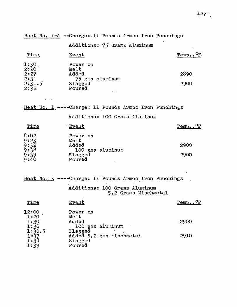
Heat No. 1-A -~Charge:.11 Pounds Armco Iron Punchi~gs·
Additions: 75 Grams Aiuminum
127 ·
Time. Event Te.mp.; °F-
1:30 2·:20. 2:27· 2:31 2:31.5 2:32
Power on Melt Added
75 gms aluminum Slagged Poured
·Heat No. l ___ .:.·-charge: 11 Pounds .Armco Tron Punchings
Time
8:02 9:23 9:32 9:38 9:39 9:4~
Additions: 100 Grams Aluminum
· Event
Power on Melt Added
100 gms aluminum Slagged Poured
. 0 Temp., F
2900
2900
Heat No. 3 ----Charge: 11 Po~nd~ A~mc-o·_ Iron Punchi~gs
Additions: 100-Grams Aluminum
Time
12.:00 1:20 1:30 1:36 1:36.5 1:37 1:38 1 :39_
Event
Power on Melt Added
5. 2 Grams . Misc!lmet.al
_· 100 gms aluminum .Slagged Added 5.2 gms mischmetal Slagg~d Poured
·2900
2910-

Heat No. 4 . -~Charge: 11 Pounds Armco Iron Punchings
Additions: 100 Grams Aluminum 1,.o·arams Mischmetal
Time
6:45 8:10· 8:17 8:22 8:23 8:23.5' 8:24.5' 8:25.5'
Event
Power. on Melt Added
100 gms aluminum Slagged · Added 15.0 gms mischmetal Slagged Poured
Temp. ,.°F
.2900
2890
Heat No. 5 --Charge: 11 P~unds Armco Iron Punchings
Additions: 100 Grams Aluminum
Time
12:48 2:10 2:18 2:23 2:23.5' 2:24 2:25' 2:26
Event
Power on Melt Added
25ol Grams Mischmetal
100 · gms aluminum Slagged Added 25'.1 gms ~SC?metal Slagged Poured
Tempo, °F
2900
2890
Heat No. 7 --Charge: 11 Pounds Armco Iron Punchings
Additions: 100 Grams Aluminum
Time.
11:25' 12:40. 12:48 12:54 12:54.5' 12:55 12:56 12:57
E·vent
Power on Melt Added
5o3 Grams Lan-c~r-amp
100 gms aluminum Slagged Added ·5.3 gms Lan-cer-amp Slagged Poured
Temp., °F'
2900
2910
128

Heat No. 8 :--Charge: 11 Pounds Armco Iron Punchings
Additions: 100 Grams Aluminum
Time
3•:15 4:36 4:45 4:50 4:51 4:51.5 4:52.5 4: 53. 5 .
15~3 Grams Lan-cer-amp Metal
Event
Power on Melt Added
100 gms aluminum Slagged Added 15.3 gms Lan-cer-amp Slagged Poured
Temp., °F.
2900
2900
Heat No. 9 --Charge: ll_Pounds Armco Iron Punchings
Additions: 100 Grams Aluminum
Time
12:00 1:23 1:30 1:35 1:35.5 1:36 1:37 1:38
25.0 Grams Lan-cer-amp Metal
Event
Power on Melt Added
100 gms aluminum · Slagged Added 25.0 gms _Lan-cer-amp Slagged Poured
Temp., °F
2900
2910
Heat No. 10 --Charge: 11 Pounds Armco I.ron Punchings
Additions: 100 Grams .Aluminum
129
5.0 Grams Rare Earth Oxide Mixture
Time
2:28 3:50 4:00 4:05 4:06 4:07 4:07.5 4:08.5 4:09
Event Temp.,°F
. Power on ·Melt Added 2910
100 gms aluminum Slagged Added 5.0 gms rare earth oxide 2900 Rare· earth oxide.stirred into melt Slagged Poured

130
Heat No. 11 --Charge: · 11 Pounds Armco Iron Punchings
Additions: 100 Grams Aluminum
Time
7:15 8:40· 8 :51 8:57 8: 57. 5 8: 58. 5 8: 59 9:00
. 9:00.5
10.0 Grams Rare Earth Oxide Mixture
Event
Power on Melt
Temp., °F · .-
Added 2900 100 gms aluminum
Slagged-Added 10.0 gms rare earth oxide 2910 Rare earth oxide stirred into melt Slagged Poured
Heat No. 12 --Charge: -11 Pounds Armco Iron Punchings
Additions_: 100 Grams Aluminum
Time
11:40 12:48 12: 58 1:03 1:03.5 1:04.5 1:05 1:05.5 1:06 1:06.5
5.1 Grams Lan-cer-amp · Metal 10.0 Grams Rare Earth Oxide Mixture
Event ~emp.,°F
Power on Melt Added 2900
lOO _gms aluminum Slagged _ Added 5.1 gms Lari-cer-amp 2890 Added 10.0 gms rare .earth oxide Rare earth oxide stirred into melt Slagged Poured

· Heat No. 13 ~-Charge: 11. Pounds Armco Iron Punchings
Additions: 100 Grams Aluminum 15.1· Grams Lan-cer-amp Metal
131
10.0 Grams Rare Earth Oxide Mixture
Time
8:15 9:37 9:45' 9:50 9: ,o. 5 9: 51. 5 9: 5'2 9:52.5 9: 5'3 . 9: 53. 5
·Event
Power · on Melt
Temp. ,·°F
Added 2890 100 gms aluminum
Slagged Added 15.1 gms Lan-cer-amp 2910 Added 10.0 gms rare earth oxide Rare earth oxide stirred in~o melt Slagged Poured
Heat No. 14 - .-Charge: 11 Pounds Armco Iron Punchings
Additions: 100 Grams Aluminum
Time
2:00 ·3 :23 3:31 3:36 3:36.5 3:37.5 3:38· · 3:38.5 3:39 3:39.5
25 .1 Grams Lan-cer-amp · 1\[etal 10.0 Grams Rare Earth ·Oxi~e Mixture
Event Temp.,°F
Power on Melt Added. 2900
100 gms aluminum Slagged Added 25.1· gms Lan-cer-amp 2910. Added 10.0 gms rare earth oxide Rar~ . ·earth oxide stirred into melt Slagged Poured

. APPENDIX. _III
Hot-Rolling and Swaging
132

~33
After cutting· the ingots in. half, and taking_ sectiqns
for metallographic examination and sUlfur'printing, the, -ma~
chined bars were placed in · the pre~heated, resistance-~yp~ . .
·furnace. The ·oars had been.machined _t~ one-inch diameters.
The furnace was· heated to 870°c in order to·_ remain jus·~ ·
· below t _he 'hot-shor~ _region. Five to six _hour_s were required
to bring the furnace to temperatur~. _No protective atmosphere
was used ·111 the furnac_e. As considerable oxide forms at this·
· temperature, identi.fication of the bars had to be watc.hed -
closely. E~ch bar uas he~ted for 30 minutes prior to rolling.
Guide tables of steel sheet and angle iro~-w~re con
structed for both the - e.ntrance and exit sides of the rolls to
both facilitate guiding the bars into the rolls and c~tching
them on the exit side.
Eight . passes were made on each bar. Two-high rolling
mills of the type used u~uall:-Y have indentations of alternat
ing rounds and ovals. The bars· were -passed in ·successi.on -from·
the 1 1/8-inch oval. to the 5'/B~inch r ·ound·.: When passing from
rounds i~to ovals, the bars· were simply -placed on ·the guide
table,· lined with the opening in- · th~ roll-s, a·nd tapped _ on the
trailing end -to _ push them in_to the -maying _ ro11·s. _ More diff 1- .
culty was encountered in passing ·rrom ovals · into __ rounds .as·
the bars had a tendency to twist. Thi·s ·was· overcome by tap~
·ping the .bars into position be~ore sta~ting the roils. This
procedure; however, was not success.ful --in making the· second
pass--from the 1 -1/8-i~ch oval into the 7/8-i~ch round. The
motor would not drive the rolls with. an obstruction of this

134
size. This pass was made by guiding the bars into the· moving
rolls with tongs. The ·bars did not twist but extreme car·e
had to be taken to prevent the tongs from being pulled into ·
the rolls.
Two passes could be made before reheating or the bars
was necessary. The l_a.st pass on each bar was- made cold to
remove mill-scale and increase the extent ot cold working.
The coid swaging was done iri six passes. The die sizes
used were: Oo650, 0.600, Oo5?0 and 0.5'00 inch, r~spect·ively.
The dies were well oiled_ before inserting into positi9n to
· prevent st~cking._ The bars were passed into the dies -by using
a pipe with an ihside -diameter or one inch and a rod with an
outside diameter of one inch. The bars were pla.ced in the
pip_e and thrust into the swaging dies by using -the rod as a
plunger.
In maki~g the 0.500-inch_pass, -~ ridge usually devel
oped whiq}:l ca:used the bars to·rotate at the same sp~ed as the
dies. The bars are supposed to· rot~te, but: at :a speeq some~
what slower than the d~es. This ·difficul~y was overcome by
gr-a·spfng the revolving bars firmly- in gloved hands -and . re
stricting the revolving until the ridges completely-disap
peared. Th~ bars were passed through the·o~500-il).ch die -three
times to insure uni:form working and symmetry.
As ·1n induction melting, r ·6lling and swaging is a two
man opera.tion. As~estos gloves were worn. to prevent burns. It
should _be emphasized that extreme .caution must be exercised
in passing the hot me·tal intc;, the -rolls.

APPENDIX IV
Sulfur Printing
135

136
Sulfur printing,_ or Baumann -printing, was originated
by Heyn and Bauer in 1906 and ·was modi:ried by Baumann. The
method is described in a number or textbooks and technical
:papers, a~ ,vell :ls in the ASTM st·andards. Sulf~ printing
a.f.fords a con-v-enlent mea.ns of detecting and permanently·
recording the d5_stribution of sul.fur in iron and steel.
The :nethod consists essentially of' placing in inti
mate contact 9n a_prepared metal suriace, photographic
brm:1ide paper which has been previous·ly soaked in a dilute
solution of sul.furic ac~d in water.
The reaction of the sulfuric acid with the sulfide
regions of the iron o·r str3el prouuces hydrogen sulf'ide gas,
which reacts with the ·silver bi--otnide in the paper emulsion,
fo~ming a cha1"'acteristic 1n·ovni to gray-black deposit of
silver sulride. The reactions may be expressed as follows:
Mes~ H2S04.~ MeS04 _f H2S
H2S f 2AgBr ~ AgzS f 2HBr
In t1ais investig_a.tion, -sect~ons were cut :from_· the
ingots at approximately one-halt inch :from the bottoms, and
at _.the tops near the beginnine of the pipes. These sec_tions
were then ground on a coarse belt grinder. This was· followed
by g·rinding through the 2, 1, 0 and 00 emery pap~rs. The sec
tions were washed thoroughly with a soap solution, · rinsed _.
with methyl alcohol, and dried under a warm air blast.
AZO F-4 contact printing paper was soaked :for five
minutes in a two per cent solution or sulf~ic acid in water.
Any photographic bromide paper would have worked equally as

137
w·ell. Contra;ry to usual. requirements for the handling of
photographic paper, the enti~e operation may be carries out·
in daylight. A two per cent solution of hydrochloric acid
in water works equally as well. The concentrated sulfuric
acid ·used to prepare the solution must be clear or the.prints
have a tendency to discolor and obliterate the printing of the sulfide regions~
After s~aking the photographic_paper, the paper was
placed emulsion side up on a ground gl·ass plate upon which a
paper towel had been pla~ed to insure intimate contact. The
excess solution was removed from the emulsion side of the
paper with a paper towel and the prepared sur.face of the ·
specimen was pressed firmly onto the printing paper. Contact
wis maintained for three miru1tes for all prints.· The prints
were then washed for five minutes to remove the remaining
acid and fixed in a .standard pyp·o s_olution. Failure to wash
the print~ in running water pr-ior to the fixing -resulted 'in
the hypo solution quickly ·becoming too acid to·rix properlyo
After fixing for fifteen minutes; the prints were washed for
one--hour in running water and dried.
The slag samples and rolled bars were printed· in
exactly the same manner. Special care was· taken i~ printing
the slag specimens to ir:isure that all · o:f the excess · acid wa·s
removed from the paper emulsion berore _printing. The slag ·
samples were porou~ and any acid would have flowed into the
pores resulting in false indications of the sulfide regionso

138
APPENDIX V
Polishing·, Etching, and Metallography

The polishing of any metal with the aim of preserving
non-metallic inclusions is a tedious task. This is espec_ial·
ly true for softer metals such as ingot iron. Not only 1·s : _· ·
there a great . tendency for - inclusions. to be pulled ou:t, but
there is also the danger of flow in the polished surface
resulting .in pseudo-structures.
Care was taken throughout the .grindfng and polishing
to use gentle _pressure for each op~ration. Gentle pressure
tends to keep flow and pulling out or· inclusions at a -mini
mum. Each step in the grinding and polishing was carried
· just to completion and no further in an. attempt to preserve
as many of the inclusions as possible.
The ·specimens were first ground on the number 120
belt grinder and then on the number 320 belt grinder. The
specimens .· were then ground successively through the 2, 1, . o, 00 and 000 emery papers. At each chang~ of emery p_aper, . the
specimen~ _were washed thoroughly and grinding was · r~sumed· in
a direction -perpendicular· to· the preyious ·grinding. _·
After grinding on the 000 emery . paper, the ·specimens
were vjashed and polished for approximately four minutes on a
billiard-cloth lap wheel with levigated alumina· abrasiveo ·
The specimens were rotated ·counterwise to the rotation 0£ ·
the lap wheel".
The specimens were washed thoroughly and polished on
a selvyt-cloth lap wheel with Linde B abrasive. Instead of
rotating counterwise to the lap, the specim~ns were held
stationary for approximately _five seconds and then rotated
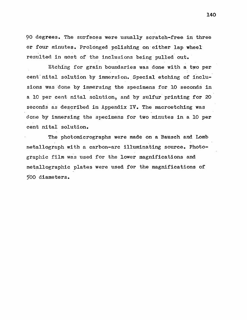
140
90 degrees • . The su1•:fe.c~s were usually scratch-free. in thre·e
or four minutes. Prolonged p~lishing on·either lap wheel
resulted in most of the inclusions being · pulled out. · . .
Etc_hing for grain boundaries was done wi ~h a · two per
cent·nital solution by immers1.on. _Special etchine of inclu
sions was ·a.one by im_mersing the specimens for 10 -seconds in
a 10 per cent nital solution, and by sulfur· printing for 20
seconds as de~~ribed in Appendix IV. The macroetching was
done by immersing the sr,ecimens for two minutes in a 10 per
cent nital solution.
The photomicrographs were made on a Bausch and Lomb
metallograph with a carbon-arc illuminating source. Photo
graphic film was used for the lower magnifications and
met~llographic plates were used for the magnifications of
500 diameters.

1.
2.
4.
6.
8.
.o.
1.
.2.
BIBLIOGRAPHY
Vogel, R. Uber Cer-Eisenlegierungen. Zeitschrift fur anorganische und allgemeine Chemie. Germany. Vol. 99,. p. 30 (1917) -
Allison, F. G., and Rock, M. · M. Studies of the m~crostructure of cast steel. · Chemical and Metallurgic~l
·Engineering. Vol. 23, pp. 383-389 (1920) .
Burgess, G. K., and Woodward, R. W. Manufacturing and properties of s ·teel plates containing zirconium and other elements. National Bureau of Standards, Technical .Paper 207. 1921.
Spring, L. W. Adds cerium to brass .and iron. Foundry. Vol. 50, pp. 542-544 (1922)
141
Gillett, H. w., and Mack, E. L. Experimental production of alloy steels. u.·s. Bureau of Mines. Bulletin 199. 1922.
Gillett, H. w., and Mack, E. L. Molybdenum, cerium and related alloy steels. N. Y., The Chemical Catalog Co., Inc., 1925. p. 226.
Post, c. B., Schoffstall, D. G., and Beaver, H. o. Hotworkability of stainless steel improved by adding cerium and lanthanum. Journal of Metals. Vol. 3," pp. 973-977B (1951)
Berry, c. D., and Dorvell, ·A. A. Effect of cerium on ductility and impact strength of steel •. American Foun-dryman. Vol. 20, pp. 45-46 (Dec. 1951) ·
Knapp, w. E., and Bolckom, ~· T. Rare earths improve properties of many ferrous metals •. Iron Age. Vol. 169, pp. 129-134 (Apr. 24, 1952)
Knapp, w. E., and Bolckom, W. T. Rare earths improve properties of many ferrous metals. Iron Age. Vol. 169, pp. 140-143 (May 1, 1952) ·
Lillieqvist, G. A., and Michelson, c. _G. Properties of cast steels improved with rare earth element additions. Journal of Metals. Vol. 4, pp. 1024-1031 (1952)
. . Lillieqvist, G. A. The effect of rare earth additions on the properties of cast steels. Metals Review. Vol. 26, P• 8 (Apr. 1953) .

142
-13. Post, C. B., and -Beaver, H. o. Rare earths in stainless brought up to date. Iron Age. Vol. 171, pp. 148-149 · (June 4, 1953) ·
14. Snellman, :M. G. A study of de_sulphurization of steel with -rare earths. ·Thesis, University of Pittsburg, Pittsburg, Pennsylvania ·{1953) .
15. · Russell, J. V. Rare earth ad~itions affect surface ·quality of low carbon steel. Journal of Metals. Vol. 6, pp. 438-442 (1954)
16.
17.
18 •
19 .•
20.
21.
22.
Henke, R. H., · and Lula, R·. A. Rare earths counteract hot rolling defects in stainless steel. Journal of Metals • . Vol~ 6, PP• 883-888 (1954) .
Tisd.ale, N. F., and Tisdalel N. F. Jr. Fine-grained iron and steel. u. s. Patent 2,6~3,661, July 13, 1954.
Jepson, J. o., and Duwez, P. Partial phase diagram of . the iron-cerium system. American Society for Metals. Transactions. Vol. 47, PP• 543-5,3 (1955)
Jackson, w. L. Rare earths in-steel castings. Metallur- · gia. Vol. 54, pp. · 233-·238 (Nov. 1956)
Tisdale, N. F., and Tisdale, N •. F. Jr. Composition of rare earth oxides for production of iron .and steel. Canadian Patent 530,5,o, September 18, 1956.· .
Wilson~ w. G. Rare eartns ~omogenize ingots. Iron Age. Vol. lt52, .·pp. 78-79 ( Oct. 2, 1958)
Tageev, v. M., and Smirnov, Yu. D. Preve~tion of A- · segrega.tion in. the solidification of steel by treatment with rare earth elements. Brut·cher Translation No. 4060 (1958) . .
23· • .- Perkins, R. A., and Binder, Wo Oo Improving hot ductility of 310· stainless. Journal of Metals. Vol. 9, ·ppo 239-245 ·(Feb. 1959) . · . . .
24. ·Singleton,' R.H. Determination of the cerium habit in carbon steel. Metallurgical Society, American Institute of Mining and Metallurgical Engineers. Transactions. · Vol. 215, PP• 6?5-679 (1959) ·
25. Yost,. D. M., Russell, H., and Garner, c. s. The rareearth elements and their compounds·. N. Y., John Wiley· and Sons, Inc~, 1947 • . 92 po · ·

26.
27.
28.
29.
30.
31.
32.
33~
34.
143
Handbook of chemistry and physics. 4lst Edition·, . Cleve- · land, ·chemical Rubber Publishi~g Company. 1959-1960. ·
Wehrman, .c. R. Inclusions in iron. Cleveland, Americ~n Society for Steel Treating, i928. 162.p.
. .
Sauveur, A. The metallography and heat treatment of iron and steel. 3rd Ed.·Cambridge, Mass., The:University Press, 1926. pp. 124-125~
Hansen, M. Constitution of binary alloys. 2nd Ed. N. Y., McGraw-Hill Book Co., Inc., ·1958. pp •. 91, 451, 581, 68.6, 705. .
Cain, J._R. Influence of· s~lphur, oxygen, copper, and manganese on the red-shortness o:r·1ron. Bureau of Standards. Technologic Paper 261. 1924.
Hilty, D., and Crafts, w. Manganese modification of· the Fe-S--0 system. Journal of Metals. Vol. 6, pp.· 959-967 (1954)
. .
Asanti, P., and-Kohlmeyer, E. Uber die thermischen· Eigenshaften der Vebindyngen.von Kobalt mit Sauerstoff Schwefel. Zeitschrift fur anorganische und. allgemeine Chemie. Germany. Vol. 265, p. 94 (1950) .
Cornelius, H. Kupfer im technischen Eisen. Berlin, . Julius Springer, 1940 p~ 95. Ellis, o. w. Further experiments·on the forg~abil!ty of steel. American Society for Steel Treating. Transactions. Vol. 21, PP• 673-70? (1933)
Sauveur, A. Steel at elevated temperatures~ Ame~ican Society for.Steel Treating. -Transactions. Vol. 17, pp. 410~448 (1930) .
Ihrig, H.K. A quantitative.hot workability test for metals. Iron Age. Vo~. · 153-2, pp. 86-89 (Apr. ·20-, 1944)
. .
37. Ihrig, H.K. The effect of various ·elements on the h~t · workability of steel. Metals Technology. Vo~. 12, pp. l-
39.
29· (Oct. 1945) · .
Clark, c. L. Evaluating steel forgeability. Iron-Age. Vol •. 153-2, PP• 5'2-5'5 (Mar. 16, 1_944) .
a • • •
Symposium on hot-working. -Iron ·and Steel Division, American Institute or Mining· and Metallurgical Engineers, Transactions. Vol. 167, PP• 735-790 (1946) . ·

400
41.
42.
44.
46.
47.
144
Carney, D. J. Gases in liquid iron and steel. Gases in metals. Cleveland, American Society tor Me.tals, 195'3. pp. 69-118. .
Kenyon, R. L. Recrystallization and grain control in ferrous .. metals. Grain control · in industrial metallurgy. Cleveland, American S~ciety for Metals, 1949. ppo 74-157.
Cushman, A. s., and Gardner, -H. A. The · corrosion and preservation of iron and steel. 1st Ed. N. Y., McGrawHill, 1910. pp •. 78-80.
Cushman, A. s. The manufacture of pure irons in openhear-th furnaces. American Society for Testing Materials. Proceedings. Vol. 11, pp. 387-416 (1911)
Cleaves, H. Eo, and Thompson, J. G. The metal-iron. 1st Ed. N .• Y., McGraw-Hill, 1935. 574 P•
Rawdon, H. s. Effect of sulfur in steel. American Society . for Testing Materials. Vol. 36, part I, pp. 88-91. (193~) .
Anderson, C. T., ·Kimbal1 7 R. W., and Cat.tori, F. Ro · . Effect of various elemen~s on hot-working characteristics and physical properties of Fe-C alloys. Journal of Metals. Vol. 5, PP• 525-529 (1953). .
Kremers, H'. E .• Rare earth ·metals. Rare meta.I~ hand hook~ York, Pa., Maple Press Company, 1954. pp. 329-345.
The Metals . Handbook, 1948 Edit·ion~. American Society :for· Metals, Cl·eveland, Ohio.

VITA
Leander Anthony Neumeier was born in St. Louis,
Missouri ·on Fe_bruary 14, 1933.- He received his secondary
-education in Monett, Missouri. From June through November,
1951 he attended Southwe~t Missouri State College in
.Springfield, Miss<;mri. · After serving four years in the
United States Air Force, he entered the Missouri School
145
. of Mines and 1letallurgy in February of 1956. During the
summers of 1956 and 1957 he was enrolled as a student at
the Missou1'i School of Mines and Metallurgy. The s·ummer of
1958 he spent in industry. He . wa_s a recipient of the Haynes
Stellite Company undergraduate · s·cholarship from September;
1957 through January, 1959. _In Janu~ry of 195'9 ,he comple
ted the requirements for the Bachelor of Science degree in
Metallurgical Engineeringo In January of 1959 he was
appointed a Research Fellowship in Metallurgical Engineering
for a ·period of one school ·year.