The Discovery Channel Telescope: Early integrationftp.lowell.edu/dct/content/publications/SPIE...
16
Copyright 2010 Society of Photo-Optical Instrumentation Engineers (SPIE Proceedings 7733-6). One print or electronic copy may be made for personal use only. Systematic reproduction and distribution, duplication of any material in this paper for a fee or for commercial purposes, or modification of the content of the paper are prohibited. The Discovery Channel Telescope: Early integration Byron Smith* a , Tomas Chylek a , Bill DeGroff a , David Finley b, , Jeffrey Hall a , Paul J. Lotz a , Brad McCreight b , Alexander Venetiou a a Lowell Observatory, 1400 W. Mars Hill Road, Flagstaff, AZ 86001; b General Dynamics Satcom Technologies, 1217 Digital Drive, Ste 101, Richardson, TX 75081 ABSTRACT The Discovery Channel Telescope (DCT) is a 4.3-meter astronomical research telescope being built in northern Arizona as a partnership between Discovery Communications and Lowell Observatory. The telescope will be able to support substantial instrument payloads at Cassegrain, Nasmyth, and prime foci, and high observing cadences. The first-light configuration will be as an f/6.1 Ritchey-Chrétien at Cassegrain with a 30 arc-minute field-of-view. Major facility work is complete, and the telescope is currently in the integration phase with first-light anticipated in 2011. We present an overview of the design and progress to date, and include plans for final integration, commissioning, and early science. Keywords: DCT, Lowell Observatory, progress report, telescope integration 1. INTRODUCTION When last reported at SPIE in 2006 1,2,3 and 2008 4,5 the Discovery Channel Telescope (DCT) project was in the preliminary design phase, with some facility construction and long lead elements in progress. The system-level preliminary design review was subsequently held in August 2007, and the critical design review in January 2009. Since then, major procurements have largely been completed and the project is now in the early integration and testing phase with almost all major components, except the secondary mirror, on site. This paper provides a brief overview of the DCT design, with more focused descriptions presented elsewhere. 6,7,8,9,10,11,12 The present status of the integration effort is described, along with future plans through the completion of integration and commissioning, and first-light instrumentation being developed for early science operations. Figure 1 shows an aerial view of the DCT facility and auxiliary building at Happy Jack, AZ. Figure 1. The Discovery Channel Telescope at Happy Jack, AZ * [email protected]; phone: 928-233-3258; fax: 928-233-3268; lowell.edu
Transcript of The Discovery Channel Telescope: Early integrationftp.lowell.edu/dct/content/publications/SPIE...

Copyright 2010 Society of Photo-Optical Instrumentation Engineers (SPIE Proceedings 7733-6). One print or electronic copy may be made for personal use only. Systematic reproduction and distribution, duplication of any material in this paper for a fee or for commercial purposes, or modification of the content of the paper are prohibited.
The Discovery Channel Telescope: Early integration
Byron Smith*a, Tomas Chyleka, Bill DeGroffa, David Finleyb, , Jeffrey Halla, Paul J. Lotza, Brad McCreightb, Alexander Venetioua
aLowell Observatory, 1400 W. Mars Hill Road, Flagstaff, AZ 86001; bGeneral Dynamics Satcom Technologies, 1217 Digital Drive, Ste 101, Richardson, TX 75081
ABSTRACT
The Discovery Channel Telescope (DCT) is a 4.3-meter astronomical research telescope being built in northern Arizona as a partnership between Discovery Communications and Lowell Observatory. The telescope will be able to support substantial instrument payloads at Cassegrain, Nasmyth, and prime foci, and high observing cadences. The first-light configuration will be as an f/6.1 Ritchey-Chrétien at Cassegrain with a 30 arc-minute field-of-view. Major facility work is complete, and the telescope is currently in the integration phase with first-light anticipated in 2011. We present an overview of the design and progress to date, and include plans for final integration, commissioning, and early science.
Keywords: DCT, Lowell Observatory, progress report, telescope integration
1. INTRODUCTION
When last reported at SPIE in 20061,2,3 and 20084,5 the Discovery Channel Telescope (DCT) project was in the preliminary design phase, with some facility construction and long lead elements in progress. The system-level preliminary design review was subsequently held in August 2007, and the critical design review in January 2009. Since then, major procurements have largely been completed and the project is now in the early integration and testing phase with almost all major components, except the secondary mirror, on site. This paper provides a brief overview of the DCT design, with more focused descriptions presented elsewhere.6,7,8,9,10,11,12 The present status of the integration effort is described, along with future plans through the completion of integration and commissioning, and first-light instrumentation being developed for early science operations. Figure 1 shows an aerial view of the DCT facility and auxiliary building at Happy Jack, AZ.
Figure 1. The Discovery Channel Telescope at Happy Jack, AZ * [email protected]; phone: 928-233-3258; fax: 928-233-3268; lowell.edu
2. REQUIREMENTS
The DCT is designed to be a general purpose research telescope to accommodate the needs of the Lowell Observatory both now and into the future. As such, it is a particularly flexible telescope, with provisions for substantial instrumentation at the prime, Cassegrain, Nasmyth, and bent-Cassegrain focal stations, relatively wide fields-of-view, and delivering seeing limited images over broad spectral bandpasses. The project scope is comprehensive, involving development of a new site on US Forest Service land, construction of the fixed and rotating enclosures, provision of a 4.3-meter coating chamber, and the development of the telescope including mount, optics, and controls ready for instrumentation. The scope includes provisions for future upgrades, including the wide-field prime focus camera, and potential very large instruments at Nasmyth. In addition, operational necessities are included (e.g. spares, design documentation, and maintenance procedures).
The following tables summarize the basic optical and mechanical specifications for the telescope. Table 1. Optical Specifications for the DCT
Optical Parameter Ritchey-Chretien Specification
Prime Focus Specification
Clear Aperture 4280mm 4200mm
Effective f/ratio f/6 f/2.3
Central obscuration 12% 11%
Field of View Ø30’ Ø2°
Image scale (15µm pixel) 0.12”/pixel 0.32”/pixel
Image quality 0.29” FWHM 0.38” FWHM
Atmospheric Dispersion Correction Optionally removable Included
UV cutoff 300nm (without ADC) 360nm
Table 2. Mechanical Specifications for the DCT
Mechanical Parameter Specification
Operating Range ±270° Azimuth & instrument, 0.4° to 85° Zenith
Slew Speed 2°/sec + 8 second settling time
Blind pointing error <2” RMS
Pointing stability <0.1”/min drift
Non-sidereal tracking ability >5”/sec (with sidereal rate guiding)
Instrument payload capability 1500kg Prime Focus 1500kg Cassegrain 4545kg Nasmyth (x2) 200kg Bent-Cassegrain (x2)
3. MOUNT
3.1 Mount design updates
Portions of the DCT mount design were leveraged from designs used on the SOAR and VISTA mounts, which reduced cost and performance risk.4 These designs included:
• Azimuth bearing
• Elevation, azimuth, and Cassegrain rotator drives
• Elevation, azimuth, and Cassegrain rotator encoders
• Cassegrain cable wrap
• Yoke
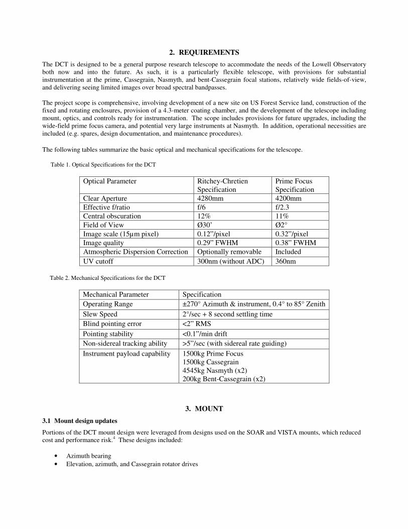
Major components of the DCT mount are illustrated in Figure 2.
Figure 2. Major components of the DCT mount
3.2 Optical Support Structure (OSS)
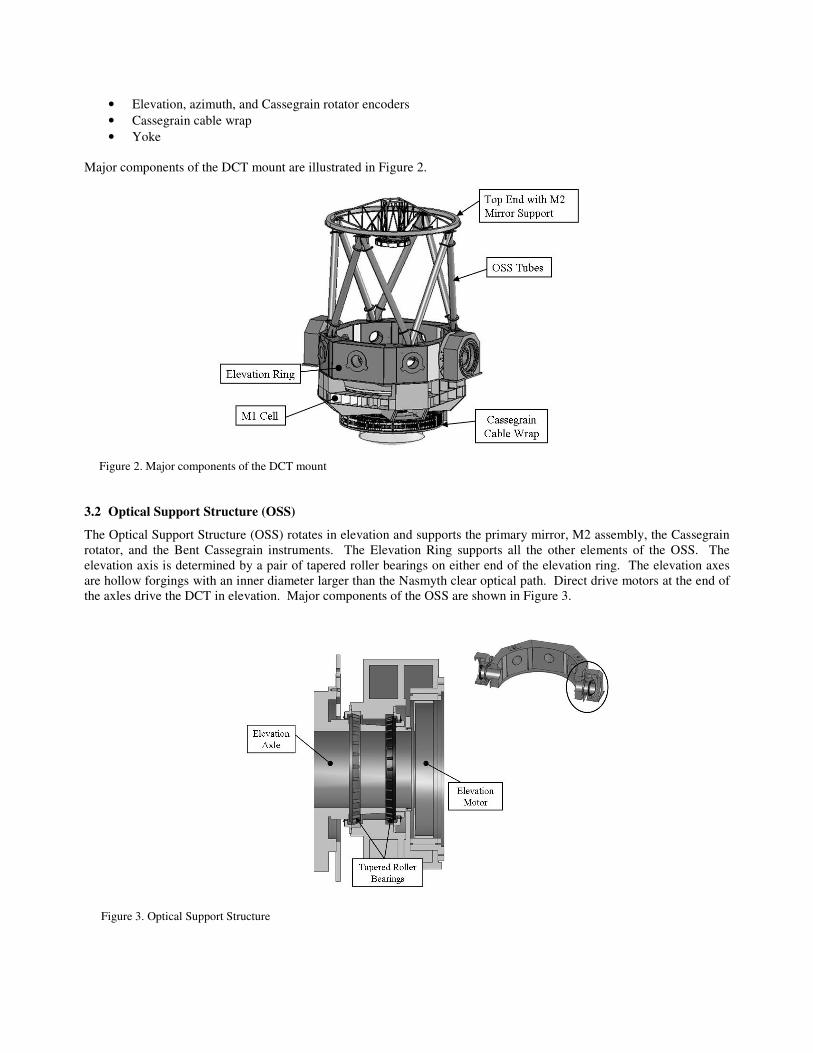
The Optical Support Structure (OSS) rotates in elevation and supports the primary mirror, M2 assembly, the Cassegrain rotator, and the Bent Cassegrain instruments. The Elevation Ring supports all the other elements of the OSS. The elevation axis is determined by a pair of tapered roller bearings on either end of the elevation ring. The elevation axes are hollow forgings with an inner diameter larger than the Nasmyth clear optical path. Direct drive motors at the end of the axles drive the DCT in elevation. Major components of the OSS are shown in Figure 3.
Figure 3. Optical Support Structure
3.3 Primary Mirror (M1) cell
The M1 Mirror Cell was designed to accommodate the mirror support actuators and be stiff enough to give adequate backing for the actuators. The back of the M1 Cell supports the Cassegrain instrument rotator and its cable wrap. The M1 assembly is designed so that it can be detached from the telescope for servicing the M1 mirror. General Dynamics SATCOM Technologies (GDST) designed and fabricated a repeatable connection between the M1 cell and the elevation ring to allow reattachment of the M1 cell without significant realignments.
3.4 Mount Top End
The Top End now includes a moderate precision (100 micron) repeatable coupling interface to accommodate interchangeable top ends. The OSS repeatable interface can be used by any future top end that may be required for other optical configurations. The installation of any particular top end will be accomplished using the observatory dome crane with telescope horizon pointing. In order for the top end coupling to repeatably locate the top end with a known tolerance, the load carried by the coupling will need to be controlled during installation using a load cell on the dome crane hook. The top end installation procedure will be to load the coupling to some percentage of the total top end load, which will provide the proper deflection for the repeatable coupling, and then secure the top end to the truss structure using captive fasteners. The top end will then be released from the dome crane and the telescope can be placed back into service.
3.5 Mount fabrication
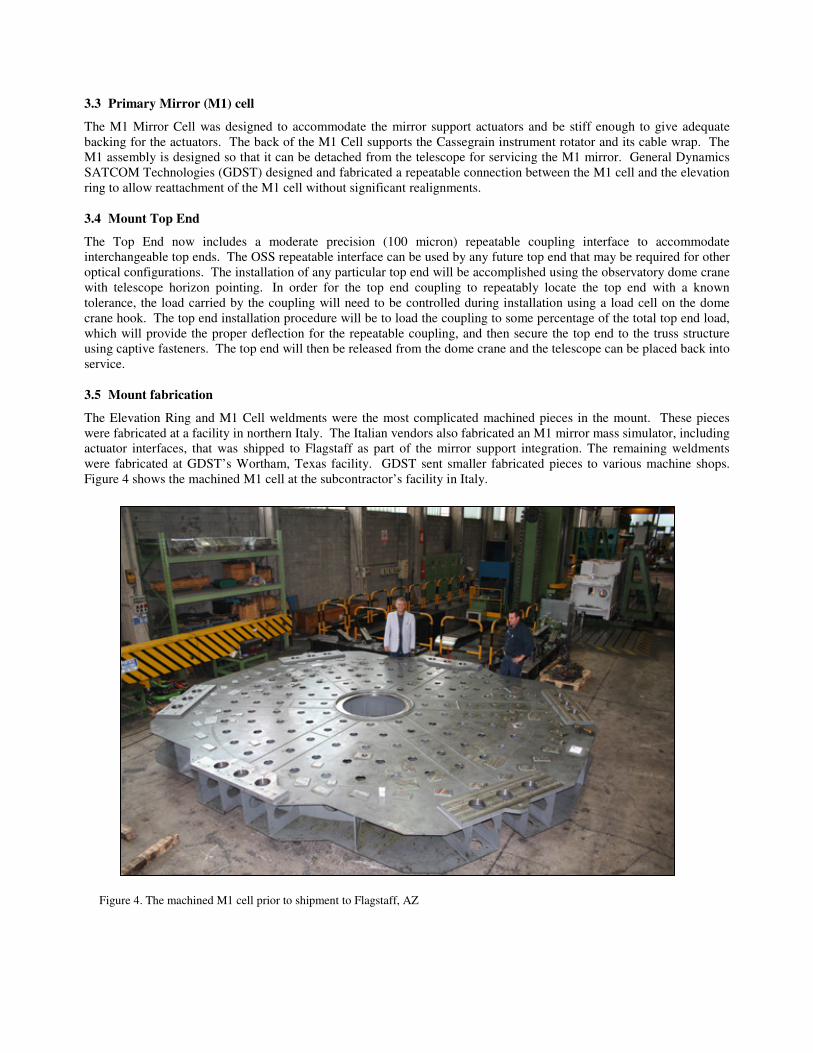
The Elevation Ring and M1 Cell weldments were the most complicated machined pieces in the mount. These pieces were fabricated at a facility in northern Italy. The Italian vendors also fabricated an M1 mirror mass simulator, including actuator interfaces, that was shipped to Flagstaff as part of the mirror support integration. The remaining weldments were fabricated at GDST’s Wortham, Texas facility. GDST sent smaller fabricated pieces to various machine shops. Figure 4 shows the machined M1 cell at the subcontractor’s facility in Italy.
Figure 4. The machined M1 cell prior to shipment to Flagstaff, AZ
3.6 Mount factory assembly and testing
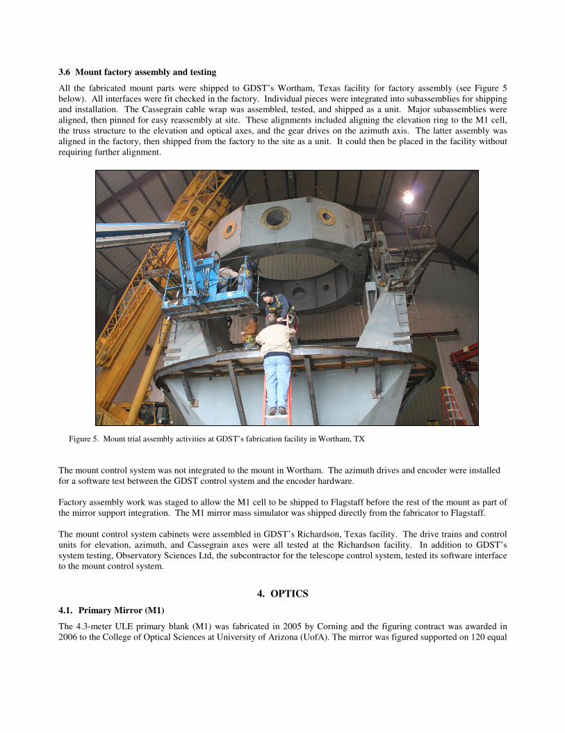
All the fabricated mount parts were shipped to GDST’s Wortham, Texas facility for factory assembly (see Figure 5 below). All interfaces were fit checked in the factory. Individual pieces were integrated into subassemblies for shipping and installation. The Cassegrain cable wrap was assembled, tested, and shipped as a unit. Major subassemblies were aligned, then pinned for easy reassembly at site. These alignments included aligning the elevation ring to the M1 cell, the truss structure to the elevation and optical axes, and the gear drives on the azimuth axis. The latter assembly was aligned in the factory, then shipped from the factory to the site as a unit. It could then be placed in the facility without requiring further alignment.
Figure 5. Mount trial assembly activities at GDST’s fabrication facility in Wortham, TX
The mount control system was not integrated to the mount in Wortham. The azimuth drives and encoder were installed for a software test between the GDST control system and the encoder hardware. Factory assembly work was staged to allow the M1 cell to be shipped to Flagstaff before the rest of the mount as part of the mirror support integration. The M1 mirror mass simulator was shipped directly from the fabricator to Flagstaff. The mount control system cabinets were assembled in GDST’s Richardson, Texas facility. The drive trains and control units for elevation, azimuth, and Cassegrain axes were all tested at the Richardson facility. In addition to GDST’s system testing, Observatory Sciences Ltd, the subcontractor for the telescope control system, tested its software interface to the mount control system.
4. OPTICS
4.1. Primary Mirror (M1)
The 4.3-meter ULE primary blank (M1) was fabricated in 2005 by Corning and the figuring contract was awarded in 2006 to the College of Optical Sciences at University of Arizona (UofA). The mirror was figured supported on 120 equal
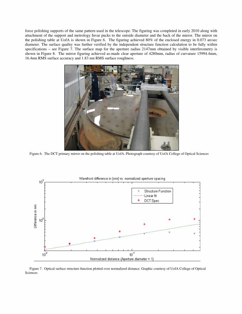
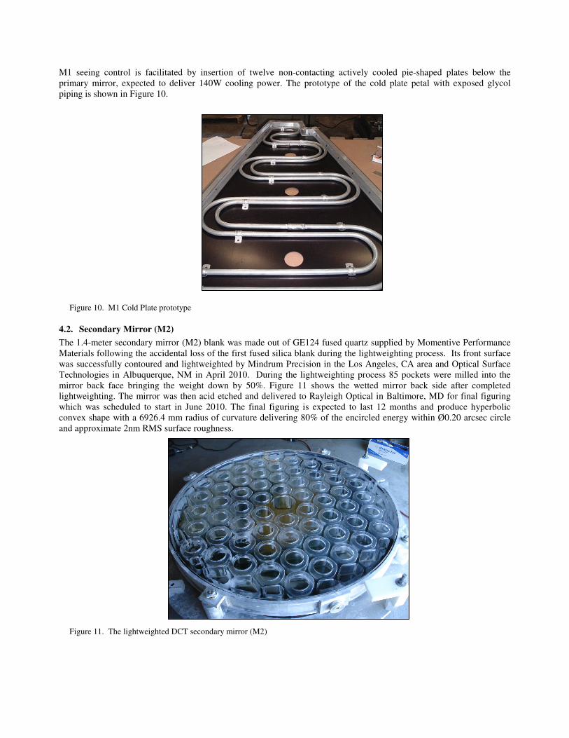
force polishing supports of the same pattern used in the telescope. The figuring was completed in early 2010 along with attachment of the support and metrology Invar pucks to the outside diameter and the back of the mirror. The mirror on the polishing table at UofA is shown in Figure 6. The figuring achieved 80% of the enclosed energy in 0.073 arcsec diameter. The surface quality was further verified by the independent structure function calculation to be fully within specifications – see Figure 7. The surface map for the aperture radius 2147mm obtained by visible interferometry is shown in Figure 8. The mirror figuring achieved as-made clear aperture of 4280mm, radius of curvature 15994.4mm, 16.4nm RMS surface accuracy and 1.83 nm RMS surface roughness.
Figure 6. The DCT primary mirror on the polishing table at UofA. Photograph courtesy of UofA College of Optical Sciences
Figure 7. Optical surface structure function plotted over normalized distance. Graphic courtesy of UofA College of Optical Sciences
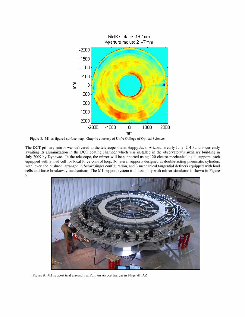
Figure 8. M1 as-figured surface map. Graphic courtesy of UofA College of Optical Sciences The DCT primary mirror was delivered to the telescope site at Happy Jack, Arizona in early June 2010 and is currently awaiting its aluminization in the DCT coating chamber which was installed in the observatory’s auxiliary building in July 2009 by Dynavac. In the telescope, the mirror will be supported using 120 electro-mechanical axial supports each equipped with a load cell for local force control loop, 36 lateral supports designed as double-acting pneumatic cylinders with lever and pushrod, arranged in Schwesinger configuration, and 3 mechanical tangential definers equipped with load cells and force breakaway mechanisms. The M1 support system trial assembly with mirror simulator is shown in Figure 9.
Figure 9. M1 support trial assembly at Pulliam Airport hangar in Flagstaff, AZ
M1 seeing control is facilitated by insertion of twelve non-contacting actively cooled pie-shaped plates below the primary mirror, expected to deliver 140W cooling power. The prototype of the cold plate petal with exposed glycol piping is shown in Figure 10.
Figure 10. M1 Cold Plate prototype
4.2. Secondary Mirror (M2)
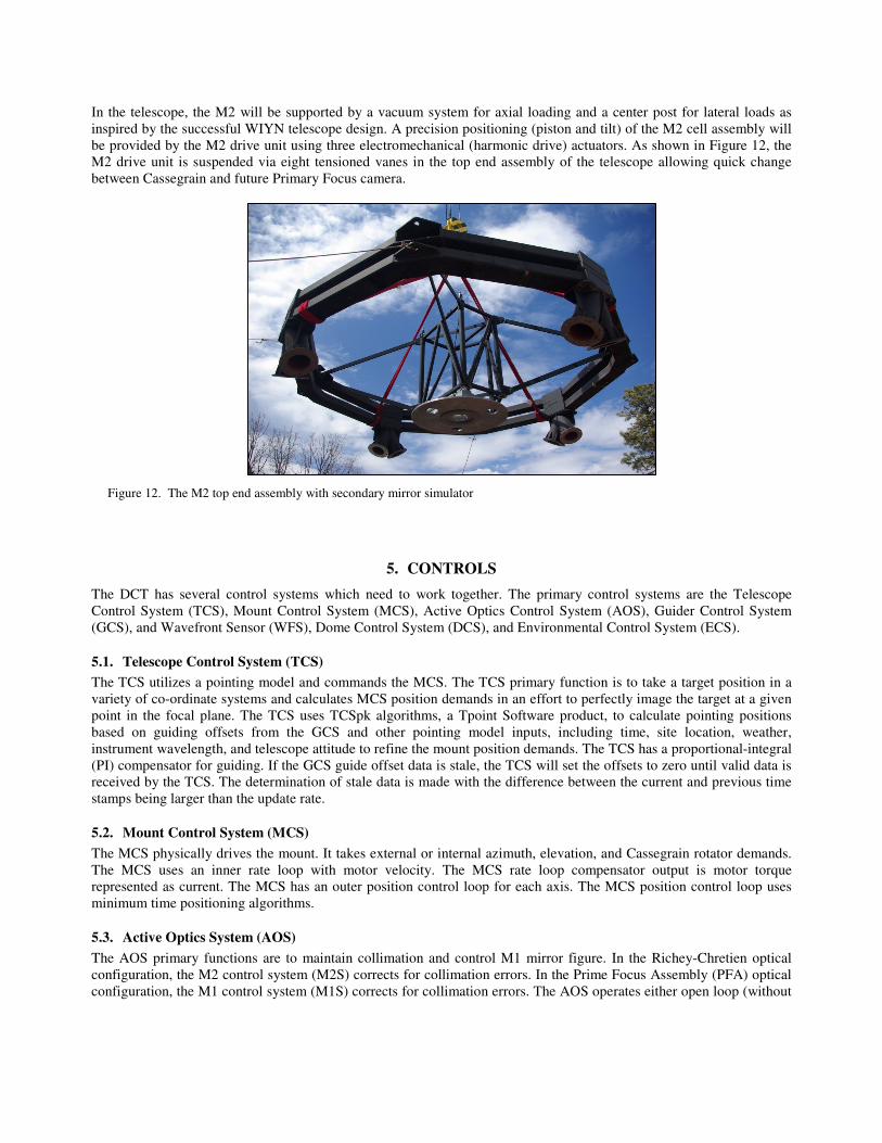
The 1.4-meter secondary mirror (M2) blank was made out of GE124 fused quartz supplied by Momentive Performance Materials following the accidental loss of the first fused silica blank during the lightweighting process. Its front surface was successfully contoured and lightweighted by Mindrum Precision in the Los Angeles, CA area and Optical Surface Technologies in Albuquerque, NM in April 2010. During the lightweighting process 85 pockets were milled into the mirror back face bringing the weight down by 50%. Figure 11 shows the wetted mirror back side after completed lightweighting. The mirror was then acid etched and delivered to Rayleigh Optical in Baltimore, MD for final figuring which was scheduled to start in June 2010. The final figuring is expected to last 12 months and produce hyperbolic convex shape with a 6926.4 mm radius of curvature delivering 80% of the encircled energy within Ø0.20 arcsec circle and approximate 2nm RMS surface roughness. Figure 11. The lightweighted DCT secondary mirror (M2)
In the telescope, the M2 will be supported by a vacuum system for axial loading and a center post for lateral loads as inspired by the successful WIYN telescope design. A precision positioning (piston and tilt) of the M2 cell assembly will be provided by the M2 drive unit using three electromechanical (harmonic drive) actuators. As shown in Figure 12, the M2 drive unit is suspended via eight tensioned vanes in the top end assembly of the telescope allowing quick change between Cassegrain and future Primary Focus camera. Figure 12. The M2 top end assembly with secondary mirror simulator
5. CONTROLS
The DCT has several control systems which need to work together. The primary control systems are the Telescope Control System (TCS), Mount Control System (MCS), Active Optics Control System (AOS), Guider Control System (GCS), and Wavefront Sensor (WFS), Dome Control System (DCS), and Environmental Control System (ECS).
5.1. Telescope Control System (TCS)
The TCS utilizes a pointing model and commands the MCS. The TCS primary function is to take a target position in a variety of co-ordinate systems and calculates MCS position demands in an effort to perfectly image the target at a given point in the focal plane. The TCS uses TCSpk algorithms, a Tpoint Software product, to calculate pointing positions based on guiding offsets from the GCS and other pointing model inputs, including time, site location, weather, instrument wavelength, and telescope attitude to refine the mount position demands. The TCS has a proportional-integral (PI) compensator for guiding. If the GCS guide offset data is stale, the TCS will set the offsets to zero until valid data is received by the TCS. The determination of stale data is made with the difference between the current and previous time stamps being larger than the update rate.
5.2. Mount Control System (MCS)
The MCS physically drives the mount. It takes external or internal azimuth, elevation, and Cassegrain rotator demands. The MCS uses an inner rate loop with motor velocity. The MCS rate loop compensator output is motor torque represented as current. The MCS has an outer position control loop for each axis. The MCS position control loop uses minimum time positioning algorithms.
5.3. Active Optics System (AOS)
The AOS primary functions are to maintain collimation and control M1 mirror figure. In the Richey-Chretien optical configuration, the M2 control system (M2S) corrects for collimation errors. In the Prime Focus Assembly (PFA) optical configuration, the M1 control system (M1S) corrects for collimation errors. The AOS operates either open loop (without
wavefront sensor) or closed loop (with wavefront sensor). The AOS processes Zernike (collimation) and bending mode (figure control) wavefront measurements from the WFS. If the WFS measurements are stale, the AOS will set the measurements to the last known valid measurements until valid data is received by the AOS. The determination of stale data is based on the difference between the current and previous time stamps being larger than the update rate. The AOS converts the wavefront measurements to M1 axial support force demands, M1 axial support position demands, and M2 axial support position demands. The AOS also uses look-up tables (LUTs) for corrections in open and closed loop operation. The LUTs use the following operational parameters: ambient temperature, M1 temperature, mount temperature, mount zenith angle, and desired focus position. Since coma (Zernikes 7 & 8) corrections will change the pointing, the AOS will send a pointing offset to the TCS.
5.4. Dome Control System (DCS)
The DCS tracks the mount azimuth position demands to keep the shutter clear aperature from vignetting the optical field of view (FOV). The DCS moves in azimuth when the difference between the mount azimuth demanded position and the dome azimuth measured position is greater than 0.5 degree. The dome will move to center the dome clear aperture with the optical path. After the move is complete, the dome will not move again until the difference is greater than 0.5 degree. The DCS also opens and closes the shutter doors. The DCS also opens and closes the shutter doors, and includes logic to prevent the shutter doors from racking (bottom of door is too far ahead of the top of the door).
5.5. Environmental Control System (ECS)
The ECS collects mount temperature, dome temperature, ambient temperature, ambient pressure, ambient relative humidity, wind speed, and wind direction. The ECS publishes the data so other systems can use it. The ECS also controls the mezzanine and dome roll up doors. Initially, the doors will be manually controlled. When enough empirical data has been collected, the doors will be automatically controlled by the ECS. The ECS will use wind speed/direction to determine which doors to have open and what percentage to open them. In the future, the ECS may use a more sophisticated algorithm which includes ambient, mount, and dome temperatures.
6. SOFTWARE
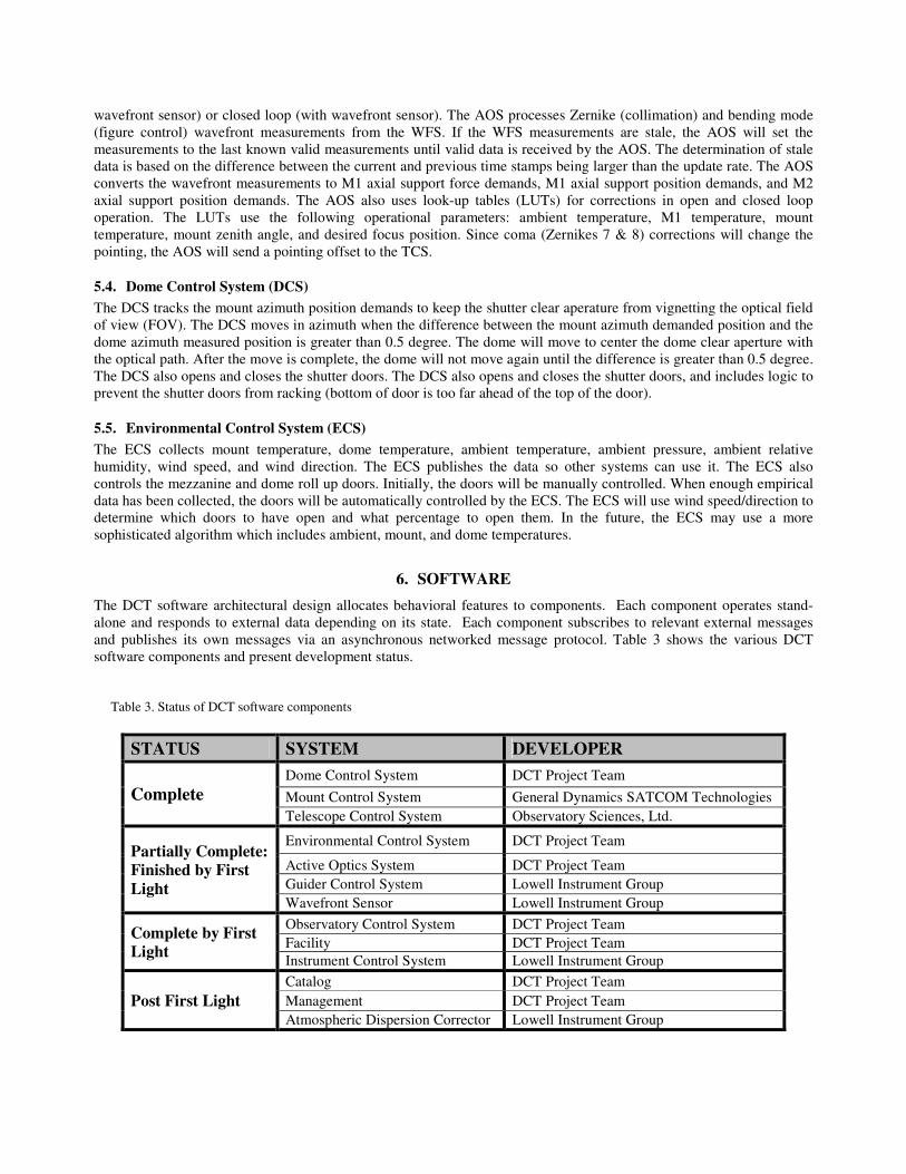
The DCT software architectural design allocates behavioral features to components. Each component operates stand-alone and responds to external data depending on its state. Each component subscribes to relevant external messages and publishes its own messages via an asynchronous networked message protocol. Table 3 shows the various DCT software components and present development status. Table 3. Status of DCT software components
STATUS SYSTEM DEVELOPER
Complete
Dome Control System DCT Project Team
Mount Control System General Dynamics SATCOM Technologies
Telescope Control System Observatory Sciences, Ltd.
Partially Complete:
Finished by First
Light
Environmental Control System DCT Project Team
Active Optics System DCT Project Team
Guider Control System Lowell Instrument Group
Wavefront Sensor Lowell Instrument Group
Complete by First
Light
Observatory Control System DCT Project Team
Facility DCT Project Team
Instrument Control System Lowell Instrument Group
Post First Light
Catalog DCT Project Team
Management DCT Project Team
Atmospheric Dispersion Corrector Lowell Instrument Group
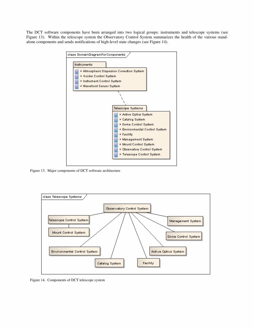
The DCT software components have been arranged into two logical groups: instruments and telescope systems (see Figure 13). Within the telescope system the Observatory Control System summarizes the health of the various stand-alone components and sends notifications of high-level state changes (see Figure 14). Figure 13. Major components of DCT software architecture Figure 14. Components of DCT telescope system

The DCT team uses National Instruments LabVIEW as the primary development environment for desktop, real-time, and FPGA applications. Messaging between LabVIEW components is via LabVIEW networked shared variables using the National Instruments Publish-Subscribe Protocol (NI-PSP). Messaging with or between nonLabVIEW components is via an ActiveMQ message broker (an implementation of the Java Message Service API). Applications encode messages sent between environments in XML. This strategy supports the communication even of complex types, including objects. The team leverages this capability to implement the Object-Oriented Command Pattern where appropriate. See other papers for more details.11,12
7. SYSTEM INTEGRATION AND TESTING
The goal of the Integration and Test activity is to assemble, deliver, and acceptance test each subsystem, culminating in an acceptance test of the overall system. See Table 4 for a summary of the development status of each subsystem. Table 4. DCT subsystems development status
Subsystem Development Status
Active Optics System (AOS)
M1 axial force and position and M1 lateral controls developed; testing is in process. M1 and M2 system software development continues; testing planned for Q3 2010. M2 vacuum system developed and prototype testing completed. M2 system software development and test planned for second quarter, 2011.
Dome Control System (DCS)
Mechanical and electrical hardware have been installed and tested; dome is controllable in manual mode. Software development in process. Site S/W testing to begin June 2010.
Environmental Control System (ECS)
Weather station hardware and software is complete. Ventilation door control design is complete. Mount and stairwell fan control design is scheduled for third quarter, 2010.
Instrument Control System
Hardware and software development in process. Testing to begin fourth quarter, 2010.
Mount Control System (MCS)
System development and factory testing complete at GDST. Site testing to begin June 2010.
Telescope Control System (TCS)
Development and acceptance test complete.
Observatory Control System (OCS)
Software development to begin fourth quarter, 2010.
Optical Coating System
System development and acceptance test complete.
By November 2009, the optical coating system had been delivered, tested, and accepted by Lowell Observatory. At about the same time, the Telescope Control System software, the TCS, was tested and delivered by Observatory Sciences, Ltd. More recently, the University of Arizona completed figuring and acceptance testing of the primary mirror. It was shipped to the telescope site in June of 2010 and will undergo coating shortly thereafter.
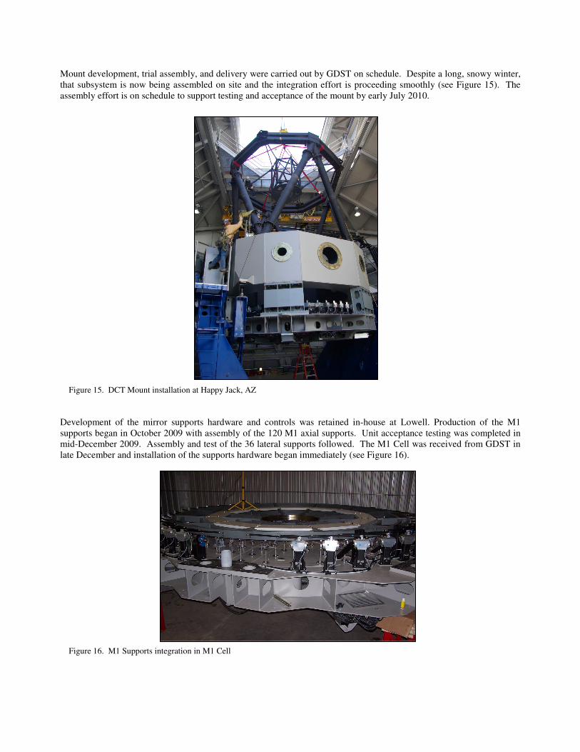
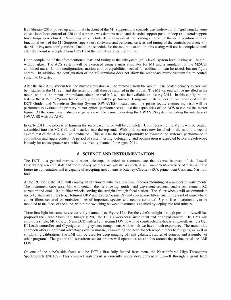
Mount development, trial assembly, and delivery were carried out by GDST on schedule. Despite a long, snowy winter, that subsystem is now being assembled on site and the integration effort is proceeding smoothly (see Figure 15). The assembly effort is on schedule to support testing and acceptance of the mount by early July 2010. Figure 15. DCT Mount installation at Happy Jack, AZ Development of the mirror supports hardware and controls was retained in-house at Lowell. Production of the M1 supports began in October 2009 with assembly of the 120 M1 axial supports. Unit acceptance testing was completed in mid-December 2009. Assembly and test of the 36 lateral supports followed. The M1 Cell was received from GDST in late December and installation of the supports hardware began immediately (see Figure 16). Figure 16. M1 Supports integration in M1 Cell
By February 2010, power-up and initial checkout of the M1 supports and controls was underway. In April simultaneous closed-loop force control of 120 axial supports was demonstrated, and the axial support position loop and lateral support force loops were closed. Remaining tests include demonstration of the homing routine for the axial position sensors, functional tests of the M1 Supports supervisory software, and performance tests and tuning of the controls parameters in the M1 subsystem configuration. Due to the schedule for the mount installation, this testing will not be completed until after the mount is accepted from GDST and the mount installer, Laron, Inc. Upon completion of the aforementioned tests and tuning at the subsystem (cell) level, system level testing will begin – without glass. The AOS system will be exercised using a mass simulator for M1 and a simulator for the M2/Cell combined mass. In this configuration, motion control capabilities needed for collimation can be tested, but not figure control. In addition, the configuration of the M2 simulator does not allow the secondary mirror vacuum figure control system to be tested. After the first AOS system test, the mirror simulators will be removed from the mount. The coated primary mirror will be installed in the M1 cell, and this assembly will then be installed in the mount. The M2 top end will be installed in the mount without the mirror or simulator, since the real M2 will not be available until early 2011. In this configuration, tests of the AOS in a “prime focus” configuration will be performed. Using one of the guider probes developed for the DCT Guider and Wavefront Sensing System (GWAVES) located near the prime focus, engineering tests will be performed to evaluate the primary mirror optical performance and test the capabilities of the AOS to control the mirror figure. At the same time, valuable experience will be gained operating the GWAVES system including the interface of GWAVES with the AOS. In early 2011, the process of figuring the secondary mirror will be complete. Upon receiving the M2, it will be coated, assembled into the M2 Cell, and installed into the top end. With both mirrors now installed in the mount, a second system test of the AOS will be conducted. This will be the first opportunity to evaluate the system’s performance in collimation and figure control. A period of system testing, debugging, and optimization is expected before the telescope is ready for an acceptance test, which is currently planned for August 2011.
8. SCIENCE AND INSTRUMENTATION
The DCT is a general-purpose 4-meter telescope intended to accommodate the diverse interests of the Lowell Observatory research staff and those of any partners and guests. As such, it will implement a variety of first-light and future instrumentation and is capable of accepting instruments at Ritchey-Chrétien (RC), prime, bent Cass, and Nasmyth foci.
At the RC focus, the DCT will employ an instrument cube to allow simultaneous mounting of a number of instruments. The instrument cube assembly will contain the field-roving guider and wavefront sensors, and a two-element RC corrector and dual 10-slot filter wheels serving the straight-through focal station. The filter wheels will accommodate up to 18 standard filters (e.g., Johnson UBV and Kron/Cousins RI) and special-use filters (including a set of narrowband comet filters centered on emission lines of important species and nearby continua). Up to five instruments can be mounted to the faces of the cube, with rapid switching between instruments enabled by deployable fold mirrors. Three first-light instruments are currently planned (see Figure 17). For the cube’s straight-through position, Lowell has proposed the Large Monolithic Imager (LMI), the DCT’s workhorse instrument and principal camera. The LMI will employ a single, 6K x 6K x 15 um CCD with a 12.5 arcmin FOV. It will be constructed in-house at Lowell, using a Gen III Leach controller and Cryotiger cooling system, components with which we have much experience. The monolithic approach offers significant advantages over a mosaic, eliminating the need for telescope dithers to fill gaps, as well as simplifying calibration. The LMI will be used for deep imaging of faint galaxies, studies of comets, and a number of other programs. The guider and wavefront sensor probes will operate in an annulus around the perimeter of the LMI FOV. On one of the cube’s side faces will be DCT’s first fully funded instrument, the Near Infrared High Throughput Spectrograph (NIHTS). This compact instrument is currently under development at Lowell through a grant from
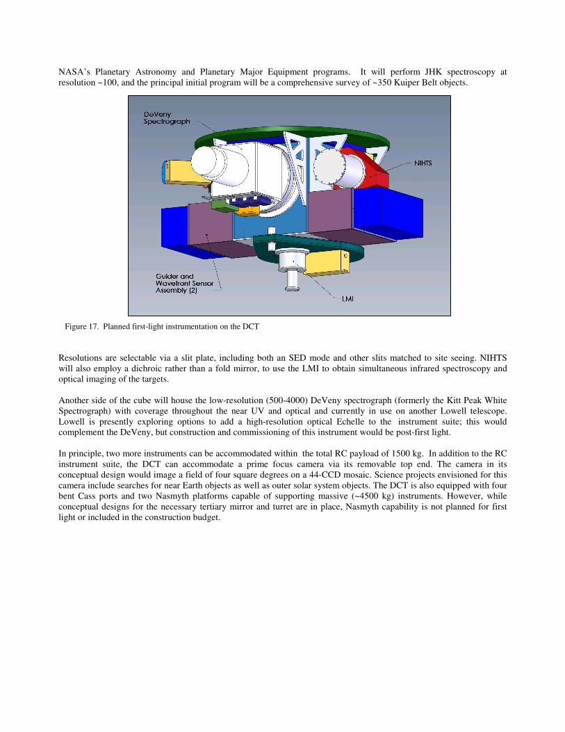
NASA’s Planetary Astronomy and Planetary Major Equipment programs. It will perform JHK spectroscopy at resolution ~100, and the principal initial program will be a comprehensive survey of ~350 Kuiper Belt objects. Figure 17. Planned first-light instrumentation on the DCT Resolutions are selectable via a slit plate, including both an SED mode and other slits matched to site seeing. NIHTS will also employ a dichroic rather than a fold mirror, to use the LMI to obtain simultaneous infrared spectroscopy and optical imaging of the targets. Another side of the cube will house the low-resolution (500-4000) DeVeny spectrograph (formerly the Kitt Peak White Spectrograph) with coverage throughout the near UV and optical and currently in use on another Lowell telescope. Lowell is presently exploring options to add a high-resolution optical Echelle to the instrument suite; this would complement the DeVeny, but construction and commissioning of this instrument would be post-first light. In principle, two more instruments can be accommodated within the total RC payload of 1500 kg. In addition to the RC instrument suite, the DCT can accommodate a prime focus camera via its removable top end. The camera in its conceptual design would image a field of four square degrees on a 44-CCD mosaic. Science projects envisioned for this camera include searches for near Earth objects as well as outer solar system objects. The DCT is also equipped with four bent Cass ports and two Nasmyth platforms capable of supporting massive (~4500 kg) instruments. However, while conceptual designs for the necessary tertiary mirror and turret are in place, Nasmyth capability is not planned for first light or included in the construction budget.
REFERENCES [1] Smith, B.W., Bida, T.A., Millis, R.L., Dunham, E.W., Wiecha, O.M. and Marshall, H.K., “Discovery Channel Telescope: progress and status,” Proc. SPIE 6267-05 (2006). [2] MacFarlane, M.J. and Dunham, E.W., “Simplifying the prime focus corrector of the Discovery Channel Telescope,” Proc. SPIE 6269-81 (2006). [3] Sabia, R., Edwards, M.J., VanBrocklin, R. and Wells, B., “Corning's success with the Discovery Channel 4.3 meter telescope,” Proc. SPIE 6273-02 (2006). [4] Finley, D.T., Squires, C., McCreight, B.A., Smith, B.W., Chylek, T. and Venetiou, A., “Design of the Discovery Channel Telescope mount,” Proc. SPIE 7012-4I (2008). [5] Blanco, D., “Estimating local seeing at the DCT facility,” Proc. SPIE 7012-3V (2008). [6] Smith, B.W., Chylek, T., Cuerden, B, DeGroff, Finley, D.T., Hall, J., Lotz, P.J., McCreight, B.A. and Venetiou, A. “The Discovery Channel Telescope: early integration,” Proc. SPIE 7733-6 (2010). [7] Smith, B.W., Chylek, T., Cuerden, B, DeGroff, B., Lotz, P.J. and Venetiou, A. “The active optics system for the Discovery Channel Telescope,” Proc. SPIE 7739-63 (2010). [8] Smith, B.W. and Manuel, S.M., “Delivered image quality budget for the Discovery Channel Telescope,” Proc. SPIE 7738-4 (2010). [9] Marshall, H.K., Bond, K. and Teran, J.U., “Design and construction of the Discovery Channel Telescope enclosure,” Proc. SPIE 7733-98 (2010). [10] Marshall, H.K., Ash, G.S. and Parsley, W.F., “The Discovery Channel Telescope optical coating system,” Proc. SPIE 7733-190 (2010). [11] Lotz, P.J., Greenspan, D., Godwin, R. and Taylor, P “Discovery Channel Telescope software development overview,” Proc. SPIE 7740-59 (2010). [12] Lotz, P.J., “Discovery Channel Telescope software key technologies,” Proc. SPIE 7740-25 (2010).