The design of reactor relief systemsTHE DESIGN OF REACTOR RELIEF SYSTEMS H A Duxbury* and A J...
15
THE DESIGN OF REACTOR RELIEF SYSTEMS H A Duxbury* and A J Wilday* Considerations relevant to the process design of reactor relief systems are discussed, and appropriate sizing methods described. The phenomena which occur when a reactor relieves are described, and the mechanisms leading to single or two- phase flow outlined. The importance of choosing the right set-pressure is explained. This methodology, together with additional aids to ease- of-use, is expected to be incorporated into the forthcoming Health and Safety Executive's Guide to Calculation Methods for Sizing Reactor Relief Systems. 1. INTRODUCTION Reactor relief system sizing has been the subject of much recent research, in particular by DIERS (the Design Institute for Emergency Relief Systems of the American Institute of Chemical Engineers). DIERS comprised 29 member companies, including ICI, and funded research costing $1.6 million between 1978 and 1985. As a result, a better understanding has been gained of the relief process, and whether or not two-phase relief can be expected. A number of new relief sizing methods were developed, including several hand- calculation methods which are very quick, easy and efficient to use. This paper is intended to give advice on the sizing of reactor relief systems for fine chemicals and speciality chemicals plant. Emphasis is therefore given to the techniques appropriate to typical problems in those industries. Reference is made to a recent review of the methodology by the authors (1) for aspects of reactor relief system sizing likely to be appropriate in other areas. It is not the purpose of this paper to discuss either the choice of worst case design conditions or the experimental techniques for providing kinetic data. However, it should be emphasised that choice of worst case design conditions is a crucial step in the vent sizing procedure and needs great care. Also, design data (usually) and scale-up data (always) have to be obtained in highly adiabatic test reactors, where heat loss from the contents to the wall is negligible. It is not sufficient to eliminate losses from the vessel to its surroundings. *ICI Engineering, PO Box 7 Northwich, Cheshire 125
Transcript of The design of reactor relief systemsTHE DESIGN OF REACTOR RELIEF SYSTEMS H A Duxbury* and A J...

THE DESIGN OF REACTOR RELIEF SYSTEMS
H A Duxbury* and A J Wilday*
Considerations relevant to the process design of reactor relief systems are discussed, and appropriate sizing methods described.
The phenomena which occur when a reactor relieves are described, and the mechanisms leading to single or two-phase flow outlined. The importance of choosing the right set-pressure is explained.
This methodology, together with additional aids to ease-of-use, is expected to be incorporated into the forthcoming Health and Safety Executive's Guide to Calculation Methods for Sizing Reactor Relief Systems.
1. INTRODUCTION
Reactor relief system sizing has been the subject of much recent research, in particular by DIERS (the Design Institute for Emergency Relief Systems of the American Institute of Chemical Engineers). DIERS comprised 29 member companies, including ICI, and funded research costing $1.6 million between 1978 and 1985. As a result, a better understanding has been gained of the relief process, and whether or not two-phase relief can be expected. A number of new relief sizing methods were developed, including several hand-calculation methods which are very quick, easy and efficient to use.
This paper is intended to give advice on the sizing of reactor relief systems for fine chemicals and speciality chemicals plant. Emphasis is therefore given to the techniques appropriate to typical problems in those industries. Reference is made to a recent review of the methodology by the authors (1) for aspects of reactor relief system sizing likely to be appropriate in other areas.
It is not the purpose of this paper to discuss either the choice of worst case design conditions or the experimental techniques for providing kinetic data. However, it should be emphasised that choice of worst case design conditions is a crucial step in the vent sizing procedure and needs great care. Also, design data (usually) and scale-up data (always) have to be obtained in highly adiabatic test reactors, where heat loss from the contents to the wall is negligible. It is not sufficient to eliminate losses from the vessel to its surroundings.
*ICI Engineering, PO Box 7 Northwich, Cheshire
125

IChemE SYMPOSIUM SERIES No. 115
2. PHASE NATURE OF FLUID ENTERING RELIEF SYSTEM
When a reactor relieves, a two-phase mixture of liquid and gas/vapour usually enters the relief system. A larger vent is usually necessary for two-phase venting, in comparison with that for gas/vapour only flow. (Some permanent gas-generating systems can be an exception to this (1)). The phenomenon of level swell, described below, is the major mechanism by which liquid enters the relief system.
When a runaway reaction causes vaporisation or gas evolution, bubbles of vapour or gas are generated within the liquid. They then tend to rise through the liquid and disengage at the surface. Whilst the bubbles remain within the liquid, they occupy volume and so cause the liquid level to rise or "swell". See Figure 1. If the level rises as far as the vent, two-phase venting will occur. DIERS has developed methods to predict the extent of level swell (2), and hence whether two-phase relief or vapour-only relief is to be expected, but these methods are valid only for systems which are not "natural" surface-active foamers.
Surface-active foaming systems tend to always fill the reactor with a homogeneous two-phase mixture during relief and to always vent a two-phase mixture. Only trace quantities of certain substances are needed in order to cause "natural" surface-active foaming behaviour. For this reason, DIERS recommended that for reactor relief, surface-active foaming should always be assumed, resulting in a homogeneous two-phase mixture entering the vent.
FIGURE 1 REACTOR LEVEL SWELL
/• \
7/y
Vapour/Gas Volumetric Evolution Rate
Low
High
M *. No1
t J ™ o r , Natural Foamer Natural Foamer
126
IChemE SYMPOSIUM SERIES No. 115
In most cases the authors follow this recommendation and assume homogeneous two-phase venting. However, there are certain cases where we have direct evidence that surface-active foaming behaviour does not occur. An example of such evidence would be the fact that a reflux condenser can be used to cool the reactor. If the mixture were a "natural" foamer, then the vessel would tend to fill with foam and the reflux condenser would be fed with a two-phase mixture and would not operate satisfactorily. Small-scale equipment for testing for natural surface-active foaming has been proposed (3).
If evidence is available that the mixture is not a "natural" foamer, then it is possible to take advantage of any disengagement which may then occur in the vessel and possibly obtain a smaller vent size. Methods are given in reference (1). It is perhaps worth making the comment that there is often little, if any, reduction in required vent size when taking account of disengagement following a period of two-phase relief. However, if account can be taken of disengagement, the cost and complexity of downstream disposal equipment is likely to be greatly reduced since it will be possible to separate the (possibly still reacting) liquid from the vapour.
3. GENERAL COMMENTS ON VENT SIZING METHODS
A considerable number of vent sizing methods are available and are discussed in (1). Many older methods continue to be valid (provided the single- or two-phase nature of the flow is recognised and the appropriate method selected). However, the new methods are much quicker to apply and tend to oversize less than all but the most time-consuming former methods. One method which is no longer recommended but Is worth mentioning because of its former ubiquity is the FIA (Factory Insurance Association) method (4). Other methods are preferable to the FIA method because of its illogical basis (heat release per unit volume, not rate of heat release), and lack of any dependence on fluid properties, pressure, phase-nature of flow, line length, and fill ratio(s). Industrial Risk Insurers (IRI), the successors to FIA, have withdrawn it from their Engineering Procedures.
Vapour or gas-only venting, is mentioned here for completeness but has limited applicability to reactor vent sizing. Two-phase flow can usually be expected to occur from a runaway reactor vent and the assumption of two-phase flow must usually be made as a safe case.
In order to help decide which methods are applicable in a given case, it is first necessary to define the chemical system as one of the following types:-
(a) "Vapour pressure systems", in which the pressure generated by the runaway reaction is due to the increasing vapour pressure of the reactants, products and/or inert solvent as the temperature rises.
(b) "Gassy systems", in which the pressure is due to a permanent gas which is generated by the reaction.
(c) "Hybrid systems", in which the total pressure is due to both vapour pressure and permanent gas generation. In some hybrid systems, the vapour generation in a vented reaction is high enough to remove sufficient latent heat to "temper" the run-away, i.e. to hold the temperature constant. This leads to a smaller required vent size.
127

IChemE SYMPOSIUM SERIES No. 115
4. CHOICE OF RELIEF DEVICE SET PRESSURE
It is often preferable to set the relief device on a reactor to operate at as low a pressure as is possible consistent with avoiding spurious operation. For a vapour-pressure or tempered hybrid system this allows the vent to open at a low temperature, when the runaway reaction is still at a relatively low rate. A low set pressure also makes it more likely that a hybrid system will temper (see 3c above).
For vapour pressure and tempered hybrid systems, a set pressure well below the design pressure is advantageous. This is because the pressure may now be permitted to rise during venting. Thus, if two-phase relief occurs, the vent can be sized such that the reactor empties sufficiently for the pressure to pass through a maximum and then fall, before the maximum vessel pressure allowable has been exceeded.
In this paper, as in many of the references quoted, the term "set-pressure" will be used to denote the pressure at which the relief device is known to be fully open. For a safety valve this will often be at 10% above the actual set pressure, since a 10% higher pressure is often needed to fully open the valve. For a bursting disc device, the (redefined)) "set-pressure" will correspond to the nominal bursting pressure plus tolerances or to the maximum specified bursting pressure of the device. The term "overpressure" will be used to mean the difference between the (redefined) set-pressure and the maximum pressure attained during the vented runaway reaction. Please note that these definitions are not the same as those used in some (e.g. British) Standards.
5. VAPOUR PRESSURE SYSTEMS
5.1 General
A large proportion of the eighty or so vent sizing applications the authors have carried out since DIERS methods became available have been for vapour pressure systems. Such systems are very common in the chemical industry, and are therefore discussed below in some detail. A large number of vent sizing methods, both pre- and post-DIERS, are applicable to vapour pressure systems. The approach given below has been found to be efficient by the authors.
DIERS methodology was originally developed assuming that vapour/liquid equilibrium is maintained in the vessel during relief. Five-gallon top-vented tests by Kirch et al (6) and a reappraisal of the DIERS styrene reacting tests by Fauske (7) have demonstrated that vapour-liquid equilibrium is often not maintained during reactor relief. However, considerations (1) of the available data indicate that the overall effect of non-equilibrium seems to be to reduce the pressure below the equilibrium value. This suggests that it is safe to assume vapour/liquid equilibrium for vent sizing purposes.
5.2 Recommended Vent Sizing Approach
For vapour pressure systems, a safe and usually acceptable vent size can be obtained by making the safe and usually realistic assumption of homogeneous two-phase relief and using Leung's method (8,3,9) to size the relief system.
128
IChemE SYMPOSIUM SERIES No. 115
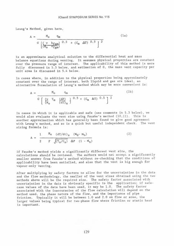
Leung's Method, given here ,
A - M0 qm (la)
° [fe%$ °'5 + <C" "' ° ' 5 J ' is an approximate analytical solution to the differential heat and mass balance equations during venting. It assumes physical properties are constant over the pressure range of interest. The applicability of this method is more fully discussed in 5.3 below, and estimation of G, the mass vent capacity per unit area is discussed in 5.4 below.
In cases where, in addition to the physical properties being approximately constant over the range of interest, both liquid and gas are ideal, an alternative formulation of Leung's method which may be more convenient is:
A - M0 qm <lb>
& -dps x 0.5 + (Cm AT) 0.5 dT)m 5
In cases in which it is applicable and safe (see comments in 5.3 below), we would also evaluate the vent size using Fauske's method (10,11). This Is another approximation which has generally been found to give good agreement with Leung's method, and so is a quick but useful independent check. The vent sizing formula is:
1 Mo (dT/dt)s ((V (XQ) (2) A -
2 F J(TS/CS) AP (1 - <*«)
If Fauske's method yields a significantly different vent size, the calculations should be reviewed. The authors would not accept a significantly smaller answer from Fauske's method without re-checking that the conditions of applicability have been satisfied, and also that the vent is big enough for vapour-only venting.
After multiplying by safety factors to allow for the uncertainties in the data and the flow methodology, the smaller of the vent sizes obtained using the two methods above will be the required size. The safety factor associated with uncertainties in the data is obviously specific to the application; if safe-case values of the data have been used, it may be 1.0. The safety factor associated with the inaccuracies of the flow calculation will depend on the method used, the phase nature of the flow, and the importance of pipe friction. Typically it will be between 1.0 and 2.0 on flow or area, the larger values being typical for two-phase flow where friction or static head is important.
129

IChemE SYMPOSIUM SERIES No. 115
In most cases, the vent size obtained in this way would be the recommended design vent size. The speed of these hand-calculations is such that the time taken for vent sizing is now largely determined by the time taken in establishing the worst case design conditions and determining the design data rather than by the vent sizing calculations themselves. We would proceed with further calculations only if both methods were inapplicable or if the vent size obtained were unacceptably large.
5.3 Applicability of Recommended Vent Sizing Methods
The applicability of Leung's method was stated in reference 12 to be limited to overpressures in the range 0-50% of the (redefined) absolute set pressure. At high overpressures the method becomes increasing conservative, i.e. it tends to overestimate the vent size required. The derivation of Leung's method (8) involves integrating the differential heat and mass balances assuming the heat evolution rate per unit mass, the vent capacity per unit area, and physical properties (latent heat, liquid specific heat and vapour/liquid specific volumes) are constant. Of these parameters, the heat evolution rate and vapour specific volume tend to be the most sensitive to pressure. In order to decide the maximum overpressure for which the method is valid in a particular application, we would compare the values of the above parameters, at the set pressure and at the proposed maximum pressure, and make a judgement as to whether the use of average values is reasonable, or whether it would be likely to lead to gross oversizing.
Leung's method includes the mass vent flow capacity per unit area, G, explicitly within the formula. This allows the user to use any applicable vent capacity calculation method.
Although Fauske's method incorporates the equilibrium rate model (15) for vent flow capacity when friction is negligible, it also includes a correction factor to extend the applicability of the method to longer vent lines of constant diameter and with negligible static head change. The method is limited to overpressure in the range 10-30% of absolute set pressure. It assumes that flow is turbulent and that the vapour behaves as an ideal gas.
Fauske's method allows account to be taken of total vapour-liquid disengagement for fluids which are not "natural" surface-active foamers. To take advantage of disengagement it is necessary to know, from calculation (2) or appropriate experiments, the vessel void fraction at disengagement, i.e. at which the vent flow would cease to be two-phase and start to be vapour-only. The method is potentially unsafe if early disengagement (before the pressure would otherwise have turned over during two-phase venting) occurs (1). The current authors would not use Fauske's method to take account of disengagement unless the disengagement would have occurred after turnaround during equilibrium homogeneous two-phase venting. The criterion (1) for safe use of Fauske's method to take account of disengagement is:
, 2 q < GA hfg v f (3)
V v f g (1 -<*d)2
When Fauske's method is used without taking account of disengagement (the more usual case), OC^ — 1 and the validity criterion, equation (3), is not needed.
130

IChemE SYMPOSIUM SERIES No. 115
5.4 Calculation of Vent Capacity per Unit Area
As stated above, Leung's method allows and requires a separate calculation of the mass vent capacity per unit area, G. The author's method of selection of the calculation method for G is discussed in detail in references 1 and 13. When calculating the vent line capacity per unit area, the authors assume that flashing to equilibrium occurs, as recommended by DIERS (14). This is a safe assumption for vent sizing purposes, since a higher flow rate would result if equilibrium was not reached in the vent. It is also likely to be a realistic assumption since the length required to reach equilibrium is only about 0.1 metres (15) and most vents will be at least this long.
The authors use the simplified form of the equilibrium rate model (ERM) below (15) to calculate vent capacity per unit area, whenever it is applicable, because it is so quick and easy to use and requires few data (and these are usually readily available).
G - dP (T (4a) dT J C
- hfg (4b)
vfg JcT
The conditions of applicability for this model are:
negligible friction ie safety valve or bursting disc with short vent pipe.
vapour and liquid are ideal.
turbulent flow.
In cases where the equilibrium rate model (ERM) is inapplicable (eg because of a long vent line, perhaps with sections of different diameter, or static head changes, or because of non-ideal physical properties) the authors use an in-house fluid flow computer program based on HTFS methods to calculate the vent capacity. When venting is via a safety valve, its sizing is usually done using the ERM. When pipework layouts are available, the fluid flow program is used to check that pressure drops upstream and downstream of the valve are acceptable. For bursting disc systems, a correction factor to the ERM for vent line length has been given (3,10). This can be useful for preliminary sizing purposes, but since it assumes a constant diameter vent pipe and no static head changes, it is of limited applicability and the final vent capacity calculation would usually be done using the fluid flow program.
As an alternative to the use of a computer program, some convenient hand-calculation methods have recently been published (16, 17, 18, 19, 20) and their use is discussed in reference (1).
5.5 Alternative Vent Sizing Methods
For cases in which neither Leung's method nor Fauske's method is applicable, and for cases where, although applicable, they give unacceptably large vent
131

IChemE SYMPOSIUM SERIES No. 115
sizes, advice is given in reference (1). In the fine chemicals industry, the reactor and vent system are often existing, so if the above methods suggest the existing vent is just too small, it may be worthwhile to try other, slightly more accurate methods, in the hope of demonstrating that the existing vent Is indeed adequate. The alternative methods include both hand-calculation methods and computerised dynamic models of the venting reactors. They tend to require more data and/or to take longer to evaluate than Leung's and Fauske's methods.
Because of their relative ease and speed of use, the authors prefer to use hand-calculation methods rather than dynamic computer models whenever possible. Also, in many cases, the quality of the data available does not justify the use of a dynamic model. There are, however, certain but infrequent cases for which a dynamic model is an indispensable tool. Dynamic models can be used, for example, to take account of high allowable overpressures, discontinuities in reaction heat release rate or external heat input rate, and, If an appropriate physical property model is available, of non-ideal physical properties. However, due to the very large amount of data required to run a computer model, there are few cases in our experience in which use of such a model is warranted, particularly in view of the accuracy of Leung's method at modest overpressures.
6. GASSY SYSTEMS
The major method of vent sizing for gassy systems Is two-phase venting to keep the pressure constant. This method was available before DIERS (5). The peak gas generation rate during the runaway is taken and the vent is sized so that the two-phase volumetric vent capacity at the maximum allowable pressure exceeds the peak volumetric gas generation rate at that pressure. An appropriate safety factor should be applied, as discussed in 5.2 above.
Q g (1 - <*> pf Q g M (5)
G G V
Two recent enhancements to this method have been proposed:-
(a) Leung (9) has produced a hand-calculation method for two-phase vent flow capacity, G, for gassy systems with negligible friction.
(b) Fauske et al (16) have produced a nomograph for vent sizing (assuming two-phase venting to keep the pressure constant). The authors would use such nomographs for preliminary estimation purposes only and would check the vent size using the formula given above and an appropriate two-phase flow capacity method.
Other methods which may sometimes be used for gassy systems are direct scale-up and computerised dynamic models of the reactor. In both cases, a reduction in required vent area relative to that from the above formula may occur since the peak gas generation rate may not be reached until after the reactor has emptied.
However, note that for gassy systems it may be dangerous to assume homogeneous two-phase venting in order to size the vent for a gas evolution rate lower than the peak. The homogeneous flow assumption gives the maximum rate of
132

IChemE SYMPOSIUM SERIES No. 115
emptying of the reactor. If any disengagement occurs, then liquid will be left in the reactor and the runaway may accelerate to the peak rate. Two-phase venting could be re-established and a larger vent than that sized for the low gas generation rate early in the runaway could be needed.
7. HYBRID SYSTEMS
The appropriate vent sizing method for a hybrid system depends on whether or not it is tempered (see 3 above). Leung and Fauske (9), give a detailed description of how to use Leung's method for tempered hybrid systems. It should be emphasised that before using a vent sizing method for tempered hybrids, it is essential to be sure that the system will indeed temper, and will continue to temper until the reaction is complete. Untempered hybrids have usually to be treated as gassy systems and the formula given in Section (6) above is recommended unless it gives impossibly large vent sizes. In such cases, use of a computerised dynamic model or direct scale-up could be appropriate (see 6 above). The total volumetric evolution rate of both gas and vapour should be used in the formula.
8. CONCLUSIONS
Hand-calculation methods, derived from the DIERS programme, can be used for reactor relief sizing in the majority of cases. Given the data, it is possible to size a vent with sufficient accuracy in a matter of hours.
Computerised dynamic models continue to be potentially the most accurate vent sizing methods. However, in most cases, the accuracy of the data available, and the significance of any increased accuracy, do not justify the increased design time needed to use these computer models.
It is occasionally possible to demonstrate that the reacting mixture has no "natural" surface-active foaming tendency. In such cases, the relief system design calculations can take advantage of vapour/liquid disengagement. A smaller vent size is sometimes possible, and design of any downstream disposal system may be simplified.
The reactor relief sizing methods, recommended by Duxbury (5), which the authors used before the DIERS methods were available, continue to be valid (provided that test data, including scale-up data, was obtained in equipment of sufficient adiabaticity). However, they tend to result in larger vent sizes, ie are more conservative and less accurate, than the new DIERS methods. They also take longer to evaluate.
IMPORTANT NOTICE
This paper is intended for guidance only. Tnere are many variables in the design, construction, and operation of plant, and its safety is the responsibility of its designer and operating staff. Neither the authors nor Imperial Chemical Industries PLC make any warranty, express or implied, regarding the accuracy or completeness of the information presented, nor do they assume any legal liability or responsibility in respect of the consequences of use of any of the information presented.
133
IChemE SYMPOSIUM SERIES No. 115
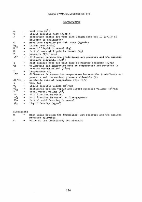
vent area (m') liquid specific heat (J/kg K) correction factor for vent line length from ref 10 (F-1.0 if friction is negligible) mass vent capacity per unit area (kg/m^s) latent heat (J/kg) mass of liquid in vessel (kg) initial mass of liquid in vessel (kg) pressure (N/m^ abs) difference between the (redefined) set pressure and the maximum pressure allowable (N/M*) heat release rate per unit mass of reactor contents (W/kg) volumetric gas generation rate at temperature and pressure in reactor during relief (m^/s) temperature (K) difference in saturation temperature between the (redefined) se pressure and the maximum pressure allowable (K) adiabatic rate of temperature rise (K/s) Time (s) liquid specific volume (m-̂ /kg) difference between vapour and liquid specific volumes (m^/kg) total vessel volume (m->) void fraction in vessel void fraction in vessel at disengagement initial void fraction in vessel liquid density (kg/m-*)
mean value between the (redefined) set pressure and the maximum pressure allowable value at the (redefined) set pressure
134
IChemE SYMPOSIUM SERIES No. 115
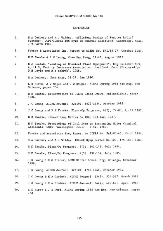
REFERENCES
1. H A Duxbury and A J Wilday, "Efficient Design of Reactor Relief Systems", CCPS/IChemE Int Symp on Runaway Reactions, Cambridge, Mass, 7-9 March 1989.
2. Fauske & Associates Inc, Report to DIERS No. FAI/83-27, October 1983.
3. H K Fauske & J C Leung, Chem Eng Prog, 39-46, August 1985.
4. E J Sestak, "Venting of Chemical Plant Equipment", Eng Bulletin N53, April 9, Factory Insurance Association, Hartford, Conn (Prepared by W H Doyle and R F Schwab), 1965.
5. H A Duxbury, Chem Engr, 31-37, Jan 1980.
6. L S Kirch, J W Magee and W W Stuper, AIChE Spring 1988 Nat Mtg, New Orleans, paper 73e.
7. H K Fauske, presentation to DIERS Users Group, Philadelphia, March 1986.
8. J C Leung, AIChE Journal, 32(10), 1622-1634, October 1986.
9. J C Leung and H K Fauske, Plant/Op Progress, 6(2), 77-83, April 1987.
10. H K Fauske, IChemE Symp Series No.102, 133-142, 1987.
11. H K Fauske, Proceedings of Intl Symp on Preventing Major Chemical Accidents, CCPS, Washington, P3.17 - 3.41, 1987.
12. Fauske and Associates Inc, Report to DIERS No. FAI/83-43, March 1984.
13. H A Duxbury and A J Wilday, IChemE Symp Series No.102, 175-186, 1987.
14. H K Fauske, Plant/Op Progress, 3(3), 145-146, July 1984.
15. H K Fauske, Plant/Op Progress, 4(3), 132-134, July 1985.
16. J C Leung & H G Fisher, ASME Winter Annual Mtg, Chicago, November 1988.
17. J C Leung, AIChE Journal, 32(10), 1743-1746, October 1986.
18. J C Leung & M A Grolmes, AIChE Journal, 33(3), 524-527, March 1987.
19. J C Leung & M A Grolmes, AIChE Journal, 34(4), 622-691, April 1988.
20. K E First & J E Huff, AIChE Spring 1988 Nat Mtg, New Orleans, paper 73d.
135

IChemE SYMPOSIUM SERIES No. 115
APPENDIX 1
EXAMPLE OF VENT SIZING FOR A VAPOUR PRESSURE SYSTEM
A 2.1 m3 reactor contains 1500 kg of reactants. Relief is to be via a bursting disc with a maximum specified bursting pressure of 3.2 bara and tail-pipe of L/D - 200. The vessel design pressure is 2.86 barg, and the maximum allowable pressure during relief is the design pressure plus 10%, ie 3.15 barg - 4.16 bara. The allowable overpressure during relief is 4.16-3.2 bar which is 30% of the absolute set pressure.
It is necessary to apply an appropriate safety factor to take account of uncertainties in the data and fluid flow calculation methods. For comparison purposes in this example a safety factor of 2 (on flow or area) has been applied to both Leung's and Fauske's methods. See 5.2 above for further discussion of safety factors.
The following data are relevant to the vent sizing calculation. Note that sufficient data has been given to allow demonstration of all methods. It would not all be required for any one method.
Pressure (Bara) Bubble point temperature (0C) Heat release rate (W/kg) Liquid density (kg/m3) Vapour density (kg/m3) Latent heat (kJAg) Liquid specific heat (kJ/kg.K) dP/dT (N/m2k) vfg (m
3/kg)
3.2 110 1150 847 3.75
674.9 1.96
8300 0.2655
4.16 120.5 1660 835 4.62
663.0 1.96
9500 0.2153
Average
115.3 1405 841 4.19
668.95 1.96
0.2404
a) Using Leung's Method
First evaluate the vent capacity per unit area, G.
An approximate way of doing this is to use the equilibrium rate model, equation (4), together with a correction factor for vent line length from reference 10. From reference 10, for an L/D of 200, a correction factor of 0.65 is needed.
Using equation (4a)
J! At 3.2 bara G - 0.65 dj?
dT - 0.65 x 8300 / 383
Vl960 - 2385 kg/ro2s
For comparison, at 3.2 bara, also evaluate using equation (4b):
G - 0.65 h fg - 0.65 x 674900 v f g JCT ( ( l / 3 . 7 5 ) - ( l / 8 4 7 ) ) ^1960 x 383
- 1907 kg/m2s
136
IChemE SYMPOSIUM SERIES No. 115
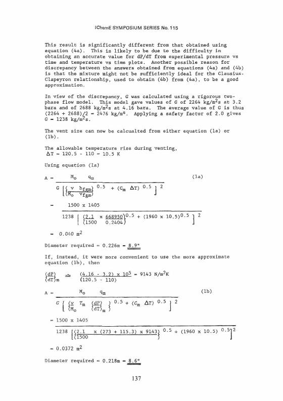
This result is significantly different from that obtained using equation (4a). This is likely to be due to the difficulty in obtaining an accurate value for dP/dT from experimental pressure vs time and temperature vs time plots. Another possible reason for discrepancy between the answers obtained from equations (4a) and (4b) is that the mixture might not be sufficiently ideal for the Clausius-Clapeyron relationship, used to obtain (4b) from (4a), to be a good approximation.
In view of the discrepancy, G was calculated using a rigorous two-phase flow model. This model gave values of G of 2264 kg/m2s at 3.2 bara and of 2688 kg/m2s at 4.16 bara. The average value of G is thus (2264 + 2688)/2 - 2476 kg/ms. Applying a safety factor of 2.0 gives G - 1238 kg/m2s.
The vent size can now be calcualted from either equation (la) or (lb).
The allowable temperature rise during venting, AT - 120.5 - 110 - 10.5 K
Using equation (la)
A - Mo qm < l a )
K v h f g W 0 - 5 + ( c m
U"o vfem) *o vfgm^
1500 x 1405
1238 f (2J, x 668_950\0-5 + (I960 x 10.5)0-5 1 2
[ (1500 0.2404J J
- 0.040 m2
Diameter required - 0.226m - 8.9"
If, instead, it were more convenient to use the more approximate equation (lb), then
(dP) ^ (4.16 - 3.2) x 105 - 9143 N/m2K (dT)m (120.5 - 110)
(lb)
f (Y Tm $dP} } 0-5 + (Cm AT) 0.5 | 2 (M0
- 1500 x 1405
| (v Tm (dP) ) 0.5 + (Cm & T ) 0.5 j
1238 [(2.1 x (273 + 115.3) x 9143) °-5 + (1960 x 10.5) 0.5i2 (1500 )
- 0.0372 m2
Diameter required - 0.218m - 8.6"
137

IChemE SYMPOSIUM SERIES No. 115
(b) Using Fauske's method
The reacting mixture is assumed to be a surface-active foamer, ie no vapour/liquid disengagement is expected, and the vessel will be assumed to vent a two-phase mixture until it is empty.
Allowable overpressure - 4.16 - 3.2 - 0.96 bar = 0.963+05 ~ / m ~
For this example, assume vent line L/D = 200 From ref 10, F - 0.65 Since no vapour/liquid disengagement can be expected, Nd = 1.0
Since Q has been taken as 1.0 (no disengagement), it is not necessary to apply the validity criterious, Equation (3)
Apply a safety factor of 2, then
Area required - 2 X 0.01596 - 0.03192 m2 Diameter - 0.2016 m - 7.9"
In this example there is only a 20% difference between the vent areas given by Leung's method and Fauske's method.

IChemE SYMPOSIUM SERIES No. 115
APPENDIX 2
EXAMPLE OF VENT SIZING FOR A GASSY SYSTEM
A 5.0 m3 reactor is to contain 3200 kg of reactants. The reactants can runaway in an exothermic reaction which evolves a permanent gas. Tests have indicated that the peak reaction rate occurs at 95°C, and at the peak rate the gas evolution rate is 0.146 litres/kg reactants/second (measured at atmospheric pressure and lS'C) and the heat evolution rate is 53 W/kg of reactants. The heat evolved vaporises liquid with a latent heat capacity of 276 kJ/kg and a molecular weight of 65. The liquid density at 95°C is 800 kg/m3. The reactor design pressure plus 10% is 4.8 bara.
Vapour evolution rate - 3200 x 53 / 276000 - 0.614 kg/s
Volumetric vapour rate at 4.8 bara and 95 C :
Q - 0.614 x 22.41 x _368 x 1.013 - 0.060 m3/s 65 273 4.8
Volumetric gas evolution rate at 4.8 bara and 95°C :
Q - 0.146E-03 x 3200 x 1.013 x 368 - 0.122 m3/s
4.8 298
Liquid volume in reactor - 3200 /800 - 4.0 m3
<X - (5.0 - 4.0)/5.0 - 0.2 The vent capacity per unit area has been calculated as 2400 kg/m2.s including safety factors to account for both uncertainties in kinetic (and other) data and uncertainties in the fluid flow calculation. For further discussion of safety factors, see 5.2 above.
. • . A -G
(0.060 + 0.122) x 800 x (1 - 0.2)
2400
- 0.0485 m2
Diameter - 0.249 m - 9.8"
139