Advanced Reactor Technologies Program Fast Reactor ... · PDF fileAdvanced Reactor...
30
Advanced Reactor Technologies Program Fast Reactor Structural Materials Sam Sham Nuclear Engineering Division Argonne National Laboratory DOE-NE Materials Crosscut Coordination Meeting August 17, 2016
Transcript of Advanced Reactor Technologies Program Fast Reactor ... · PDF fileAdvanced Reactor...
Advanced Reactor Technologies Program
Fast Reactor Structural Materials
Sam Sham
Nuclear Engineering Division
Argonne National Laboratory
DOE-NE Materials Crosscut Coordination Meeting
August 17, 2016

Presentation Outline
Introduction of Advanced Reactor Technologies (ART)
Advanced Materials R&D Program
Highlight modeling activity of Fast Reactor Structural
sub-area

Nuclear Energy Plays an Important Role in US Electrical Generation
Sankey Diagram Depicting the Flow of Energy Resources (Left) to End-Use Sectors (right).
Estimated U.S. Energy Use in 2014: ~ 98.3 Quadrillion BTU.
DOE Quadrennial Technology Review, September 2015
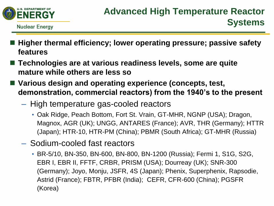
Advanced High Temperature Reactor
Systems
Higher thermal efficiency; lower operating pressure; passive safety
features
Technologies are at various readiness levels, some are quite
mature while others are less so
Various design and operating experience (concepts, test,
demonstration, commercial reactors) from the 1940’s to the present
– High temperature gas-cooled reactors
• Oak Ridge, Peach Bottom, Fort St. Vrain, GT-MHR, NGNP (USA); Dragon,
Magnox, AGR (UK); UNGG, ANTARES (France); AVR, THR (Germany); HTTR
(Japan); HTR-10, HTR-PM (China); PBMR (South Africa); GT-MHR (Russia)
– Sodium-cooled fast reactors
• BR-5/10, BN-350, BN-600, BN-800, BN-1200 (Russia); Fermi 1, S1G, S2G,
EBR I, EBR II, FFTF, CRBR, PRISM (USA); Dourreay (UK); SNR-300
(Germany); Joyo, Monju, JSFR, 4S (Japan); Phenix, Superphenix, Rapsodie,
Astrid (France); FBTR, PFBR (India); CEFR, CFR-600 (China); PGSFR
(Korea)
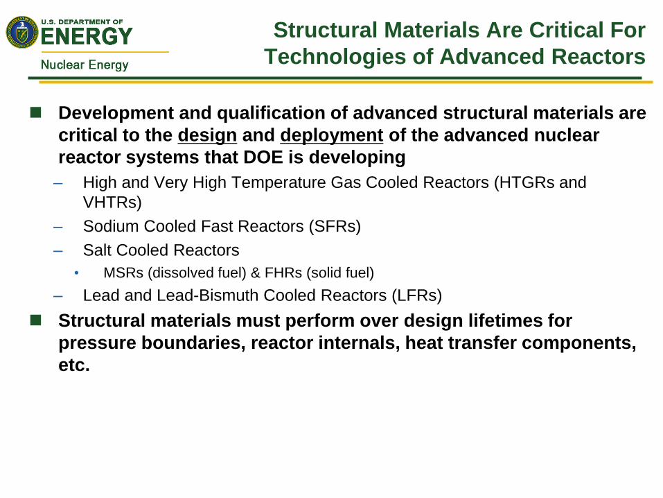
Structural Materials Are Critical For
Technologies of Advanced Reactors
Development and qualification of advanced structural materials are
critical to the design and deployment of the advanced nuclear
reactor systems that DOE is developing
– High and Very High Temperature Gas Cooled Reactors (HTGRs and
VHTRs)
– Sodium Cooled Fast Reactors (SFRs)
– Salt Cooled Reactors
• MSRs (dissolved fuel) & FHRs (solid fuel)
– Lead and Lead-Bismuth Cooled Reactors (LFRs)
Structural materials must perform over design lifetimes for
pressure boundaries, reactor internals, heat transfer components,
etc.

Advanced Materials R&D Activities under
Advanced Reactor Technologies Program
A variety of research and development (R&D) activities in the
Advanced Materials area are being conducted to significantly
improve
– Efficiency, safety, performance, and economics of advanced
reactor systems
In addition to the operating temperature range, selection of
construction materials for an advanced reactor is critically
dependent on the coolant system
– Due to material compatibility and mass transfer issues
– Particularly for the lengthy design lifetime desired to reduce
the levelized capital cost
Different construction materials are often required for different
advanced reactor systems
Quality assurance (QA) of data plays a vital role in establishing
confidence in the R&D results developed by the ART Program
Data are generated to the ASME NQA-1 quality level or its
equivalent
AFR-100
HTR

Advanced Materials Program Elements
Break Down Along Reactor Environments
Advanced Materials R&D
High Temperature Materials
Technical Lead: Richard Wright, INL
Graphite
Technical Lead: Will Windes, INL
Fast Reactor Structural
Technical Lead: Sam Sham, ANL

Significant Milestones of High
Temperature Materials Program
VHTR Pressure Vessel
Materials (SA508, 9Cr-
1Mo-V) Procurement
and Technology Gaps
Assessment
Characterization of
Alloy 617 and 800H High
Temperature Properties
and Design Rules
Development for Steam
Generator and Heat
Exchanger Applications
High Temperature
Ni-Cr-Co-Mo
Material (Alloy 617)
Code Qualification
Developed ASME Alloy 617
Low Temperature and High
Temperature Code Cases;
Currently Being Balloted
2007
(NGNP)
2016
Address Potential
Structural Integrity Issues
Beyond the ASME Code
space; Support NRC
Licensing and Long Term
Plant Operations
2022
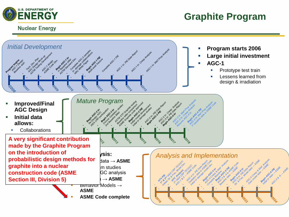
Mature Program
Initial Development
Analysis and Implementation
Graphite Program
Program starts 2006
Large initial investment
AGC-1
Prototype test train
Lessens learned from design & irradiation
Improved/Final AGC Design
Initial data allows:
Collaborations
Model dev.
Initial irr analysis
Data analysis:
Baseline data → ASME
Mechanism studies data → AGC analysis
AGC data → ASME
Behavior Models → ASME
ASME Code complete
A very significant contribution
made by the Graphite Program
on the introduction of
probabilistic design methods for
graphite into a nuclear
construction code (ASME
Section III, Division 5)

Fast Reactor Structural Program – Advanced Materials Development
2008
Established Alloy
Development Priority List
2009-2012
Alloys Downselection
2013-2015
Intermediate Term Testing
to Confirm Enhanced
Properties
• Considered a large class of
structural materials for further
development
• Involved 5 U.S. national
Laboratories and 5 U.S.
universities
• Considered experience from
Fusion, Gen IV, Space
Reactor, and development
activities in Fossil Energy
• Established alloy development
priority list: ─ Ferritic-Martensitic steels
• Grade 92 (NF616)
• Grade 92 with thermo-
mechanical treatment (TMT)
─ Austenitic stainless steels
• HT-UPS
• NF-709
• Established comprehensive downselection
metrics
• Considered tensile properties, creep,
creep-fatigue, toughness, weldability,
thermal aging, sodium compatibility,
mechanical and TMT processes
• Integrated R&D activities by DOE Labs Oak Ridge National Laboratory
Argonne National Laboratory
Idaho National Laboratory
• Materials considered include Optimized-Gr92, Ta/Ti/V-modified 9Cr, Gr92,
Gr91 (baseline material)
HT-UPS (Fe-14Cr-16Ni), Modified HT-UPS,
A709 (Fe-22Cr-25Ni), 316H (baseline material)
• Based on overall performance w/
comprehensive metrics (and accelerated
test data), Optimized-Gr92 with TMT and
A709 were downselected for further
assessment
• Further optimize
mechanical and TMT
processes
• Procure larger heats
• Validate performance
gains
• Longer-term testing of
base metals and
weldments
• Irradiation campaign
planning
• Development of roadmap
for ASME nuclear code
cases

Fast Reactor Structural Program
– Materials Design Technology
Conduct research and development on advanced
materials in support of code qualification and codes
and standards development required to apply the
materials for SFR applications
Allowing more flexible designs and/or enhancing
safety margins through design methods improvement
Gap analysis conducted in 2009 on required actions
on materials and ASME code development to
support design, construction, licensing and long term
operation
Modified 9Cr-1Mo steel and its associated
weldments have been the focus
Work scope also supports U.S.-Japan CNWG
bilateral on fast reactor materials
2009, Gap Analysis
2009-2013, Initial design methods development
2014-2016, Phase I Bilateral
2017-2020, Phase II Bilateral
2017-2025, Long term aging and sodium exposure
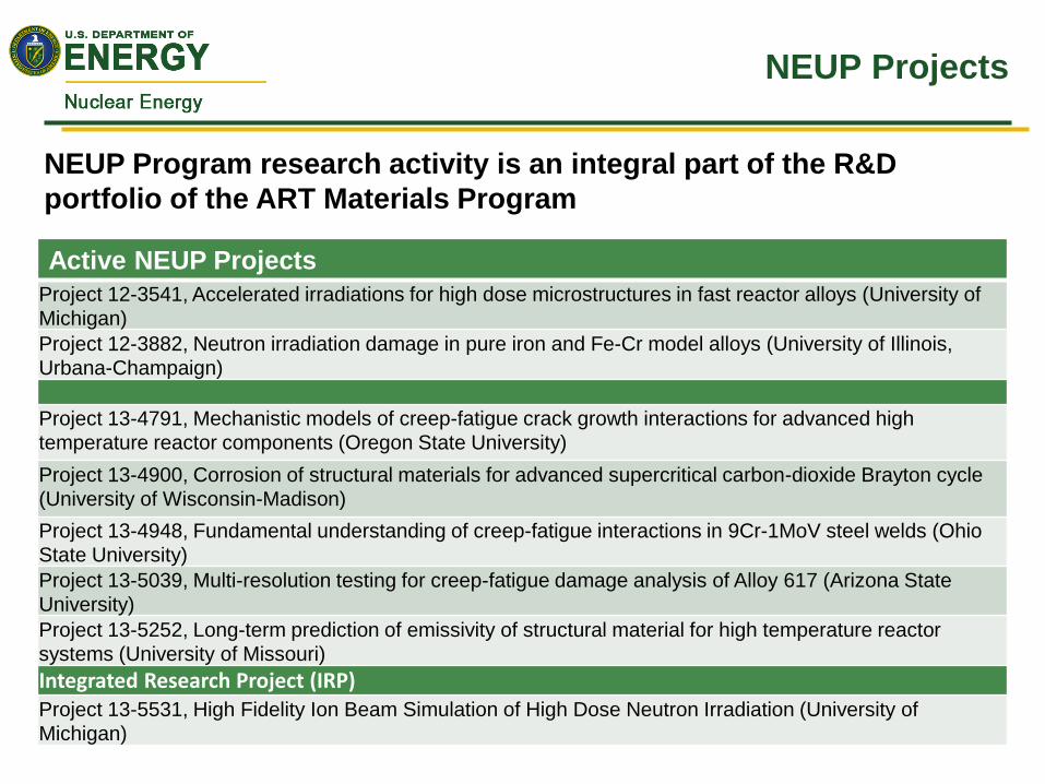
NEUP Projects
Active NEUP Projects
Project 12-3541, Accelerated irradiations for high dose microstructures in fast reactor alloys (University of
Michigan)
Project 12-3882, Neutron irradiation damage in pure iron and Fe-Cr model alloys (University of Illinois,
Urbana-Champaign)
Project 13-4791, Mechanistic models of creep-fatigue crack growth interactions for advanced high
temperature reactor components (Oregon State University)
Project 13-4900, Corrosion of structural materials for advanced supercritical carbon-dioxide Brayton cycle
(University of Wisconsin-Madison)
Project 13-4948, Fundamental understanding of creep-fatigue interactions in 9Cr-1MoV steel welds (Ohio
State University)
Project 13-5039, Multi-resolution testing for creep-fatigue damage analysis of Alloy 617 (Arizona State
University)
Project 13-5252, Long-term prediction of emissivity of structural material for high temperature reactor
systems (University of Missouri)
Integrated Research Project (IRP) Project 13-5531, High Fidelity Ion Beam Simulation of High Dose Neutron Irradiation (University of
Michigan)
NEUP Program research activity is an integral part of the R&D
portfolio of the ART Materials Program

Active NEUP Projects
Project 14-6346, Integrated computational and experimental study of radiation damage effects in Grade 92
Steel and Alloy 709 (University of Tennessee-Knoxville)
Project 14-6562, Development of novel functionally graded transition joints for improving the creep strength
of dissimilar metal welds in nuclear applications (Lehigh University)
Project 14-6762, Microstructural evolution of advanced ferritic/martensitic alloys under ion irradiation
(University of Illinois, Urbana-Champaign)
Project 14-6803, Dissimilar joints between 800H alloy and 2¼Cr & 1Mo steel (Pennsylvania State University)
Project 15-8308, Creep and creep-fatigue crack growth mechanisms in Alloy 709 (North Carolina State
University) Project 15-8432, Multi-scale experimental study of creep-fatigue failure initiation in a 709 Stainless Steel
alloy using high resolution digital image (University of Illinois, Urbana Champaign) Project 15-8548, Assessment of Aging Degradation Mechanisms of Alloy 709 for Sodium Fast Reactors
(Colorado School of Mines)
Project 15-8582, Mechanistic and Validated Creep/Fatigue Predictions for Alloy 709 from Accelerated
Experiments and Simulations (North Carolina State University) Project 15-8623, Characterization of Creep-Fatigue Crack Growth in Alloy 709 and Prediction of Service
Lives in Nuclear Reactor Components (University of Idaho)
NEUP Projects – Cont’d

New NEUP Projects
NEUP Project 16-10578: Thermal Hydraulic & Structural Testing and Modeling of Compact Diffusion-Bonded
Heat Exchangers for Supercritical CO2 Brayton Cycles (Georgia Institute of Technology)
PNEUP Project 16-10714: ASME Code Application of the Compact Heat Exchanger for High Temperature
Nuclear Service (North Carolina State University)
NEUP Project 16-10324: Model Calibration-Based Design Methodologies for Structural Design of
Supercritical CO2 Compact Heat Exchangers under Sustained Cyclic Temperature and Pressure Gradients
(Oregon State University)
NEUP Project 16-10285: Tribological Damage Mechanisms from Experiments and Validated Simulations of
Alloy 800H and Inconel 617 in a Simulated HTGR/VHTR Helium Environment (Purdue University)
NEUP Project 16-10732: High Temperature Tribological Performance of Ni Alloys Under Helium Environment
for Very High Temperature Gas Cooled Reactors (VHTRs) (Texas A&M University)
NEUP Project 16-10210: Tribological Behavior of Structural Materials in High Temperature Helium Gas-
Cooled Reactor Environments (University of Wisconsin, Madison)
FY 2017 New Calls RC-1 Materials Compatibility for High-Temperature Liquid Cooled Reactor Systems
RC-3 SiC/SiC Composites
Integrated Research Project (IRP) RC-1: Codification of Compact Heat Exchanger Usage for Nuclear
Systems
NEUP Project - $800K over three years
IRP on Compact Heat Exchangers - $5M over three years
NEUP Projects – Cont’d

Creep Deformation and Fracture Modeling of
Grade 91 Steel
Fast Reactor Structural

Acknowledgments
Grain boundary and interior material boundary modeling
– Robert Dodds Jr., Emeritus M.T. Geoffrey Yeh Endowed Chair Professor
– Kristine Cochran, consultant
Crystal plasticity modeling
– Tim Truster, University of Tennessee
Overall modeling framework
– David Parks, Massachusetts Institute of Technology

Allowable Stresses for 60-year Design
Life
Grade 91 steel is a creep-strength enhanced ferritic/martensitic steel that has been selected
as a reference construction material for a number of sodium fast reactor (SFR) designs
– AFR-100 being developed by DOE and designs from Japan, Korea and India
Long design lifetime, typical 60 years, reduces the levelized cost of electricity and hence
improves the economics of SFR plants
Desirable to design pressure boundary and core support components that would operate for
the entire design life of the plant, without replacement
ASME Code design allowable stresses depend on design lifetime and operating temperature
Extrapolation of creep rupture data using a factor of 3X on rupture time is permitted by
ASME Code for creep strength enhanced ferritic/martensitic steels such as Grade 91
For 60-year design life (500,000h assuming 95% plant availability), data with rupture times
up to 167,000h are required
Time-temperature engineering parameter such as Larson-Miller parameter is used by ASME
Code to combine data from different temperatures and rupture times to perform
extrapolation

Allowable Stresses for 60-year Design
Life – Cont’d
Whether adequate conservatism is retained when extrapolating allowable stress data is a
long standing issue that has been considered by the U.S. Nuclear Regulatory Commission
(NRC) and its Advisory Committee on Reactor Safeguards (ACRS) as one of the high
priority issues that need to be resolved for high temperature reactor system designs.
An R&D program to elucidate and to understand important features of creep deformation
and fracture behaviors through material characterization and modeling was recommended
by ANL
Modeling involves the use of high-performance continuum mechanics simulation tools and
the incorporation of mechanism-based constitutive models of deformation and
microstructural evolution
Objective is to corroborate the conservatism of the ASME time-dependent allowable
stresses obtained by extrapolation, and to retire this issue before the license application of
an SFR design.
Microstructures and Creep Fracture
Process of Grade 91 are Complex
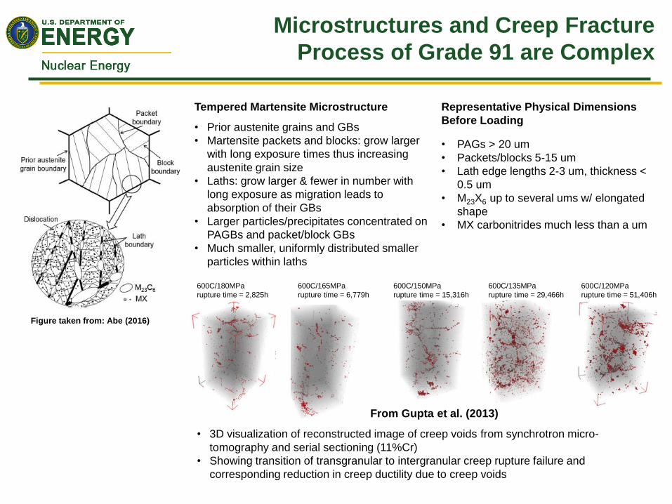
Tempered Martensite Microstructure
• Prior austenite grains and GBs
• Martensite packets and blocks: grow larger
with long exposure times thus increasing
austenite grain size
• Laths: grow larger & fewer in number with
long exposure as migration leads to
absorption of their GBs
• Larger particles/precipitates concentrated on
PAGBs and packet/block GBs
• Much smaller, uniformly distributed smaller
particles within laths
• PAGs > 20 um
• Packets/blocks 5-15 um
• Lath edge lengths 2-3 um, thickness <
0.5 um
• M23X6 up to several ums w/ elongated
shape
• MX carbonitrides much less than a um
Representative Physical Dimensions
Before Loading
• 3D visualization of reconstructed image of creep voids from synchrotron micro-
tomography and serial sectioning (11%Cr)
• Showing transition of transgranular to intergranular creep rupture failure and
corresponding reduction in creep ductility due to creep voids
600C/165MPa
rupture time = 6,779h
600C/180MPa
rupture time = 2,825h
600C/150MPa
rupture time = 15,316h
600C/135MPa
rupture time = 29,466h
600C/120MPa
rupture time = 51,406h
From Gupta et al. (2013)
Figure taken from: Abe (2016)

Finite Element Modeling Details - Prior
Austenite Grain and Packet Boundaries
Interior Boundaries:
• PAG boundaries and packet
boundaries are explicitly modeled
using cohesive finite elements
• Cavity nucleation, growth and
coalescence
• GB Sliding
Cavity growth model: Based on results from
coupled GB diffusion and creep deformation
models of Rice and Needleman (1980) and Sham
and Needleman (1983)
Cavity nucleation Model: Based on a synthesis
of literature models. Nucleation rate is driven by a
combination of normal traction to the boundary
and neighboring creep rate

Finite Element Modeling Details
- PAG and Block Boundaries (Cont’d)
GB Sliding: Based on a model given by Ashby (1972)
where the shear stress is proportional to the relative GB
sliding:
; 8
b b
B
kT
bD
1012
107
102
103
0 20 40 60 80
20o
10o
Misorientation angle, θ
Simple dependence of ηb
on misorientation angle
adopted for Grade 91,
guided by the Ashby
model (1972)
The GB sliding resistance is related to
the GB misorientation angle
LAGBs have small diffusion coefficients
and thus large ηb; high angle grain
boundaries (HAGBs) have high diffusion
coefficients and thus small ηb
3D cell simulations demonstrated that ηb > 1012 (MPa-hr-
mm-1) effectively eliminates GB sliding for the grain
property values of Grade 91. Values of ηb < 103 to 4
effectively allow free sliding.
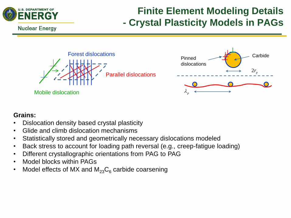
Finite Element Modeling Details
- Crystal Plasticity Models in PAGs
Grains:
• Dislocation density based crystal plasticity
• Glide and climb dislocation mechanisms
• Statistically stored and geometrically necessary dislocations modeled
• Back stress to account for loading path reversal (e.g., creep-fatigue loading)
• Different crystallographic orientations from PAG to PAG
• Model blocks within PAGs
• Model effects of MX and M23C6 carbide coarsening
Forest dislocations
Parallel dislocations
Mobile dislocation
Pinned
dislocations
2 pr
p
Carbide

Modeling Development Work Flow
• Grain boundary and interior
boundary modeling:
• Develop cohesive elements
incorporating GB cavitation and
sliding
• Coupled with isotropic material
model (power law creep) for the
grains to test development
• Crystal plasticity (CP)
development and
implementation to model grain
deformation
• Test (CP) development without
introducing GB and interior
boundaries
• Integrate both components to
study creep deformation and
fracture

Preliminary 3D Grain Boundary Model
Results (Without Crystal Plasticity)
(No GBs, reference solution)
Kimura, et al. (2009)
(cell strain rate)
• Model shows a clear
primary-like creep effect up
to ~600 hours
• Free GB sliding
• Strain rate decreases until
grain-to-grain contact
conditions and shear
stress on GBs reach a
steady state
Model with freely
sliding grain
boundaries
Nucleation of new cavities: off
Fixed properties for these simulations
Grade 91
600C/120MPa
Primary creep trend caused by stress re-distribution of high stresses at triple points
caused by grain boundary sliding

3D Simulation Results – Video of
Deformation
Deformations to scale
Kimura, et al.

3D Simulation Results – Video of GB
Porosity Evolution
• Only GBs become visible
• First shown when (a/b0)2 > 0. 5
• Damaged GBs mostly normal to
loading direction ( Y )
Deformations to scale
time(hrs) Cellstrain #failedGBs
4960 0.010 0
6960 0.015 3
8460 0.020 12
10460 0.030 39
12460 0.050 67
13460 0.080 90
14210 0.120 106
467 GBs in model
Kimura, et al. (tests)
100 grain cell (0.2 x 0.2 x 0.2 mm)
120 MPa traction on Y = 0.2 mm
X = Y = Z = 0 symmetry planes
MPCs enforce uniform normal displacements on each cell surface
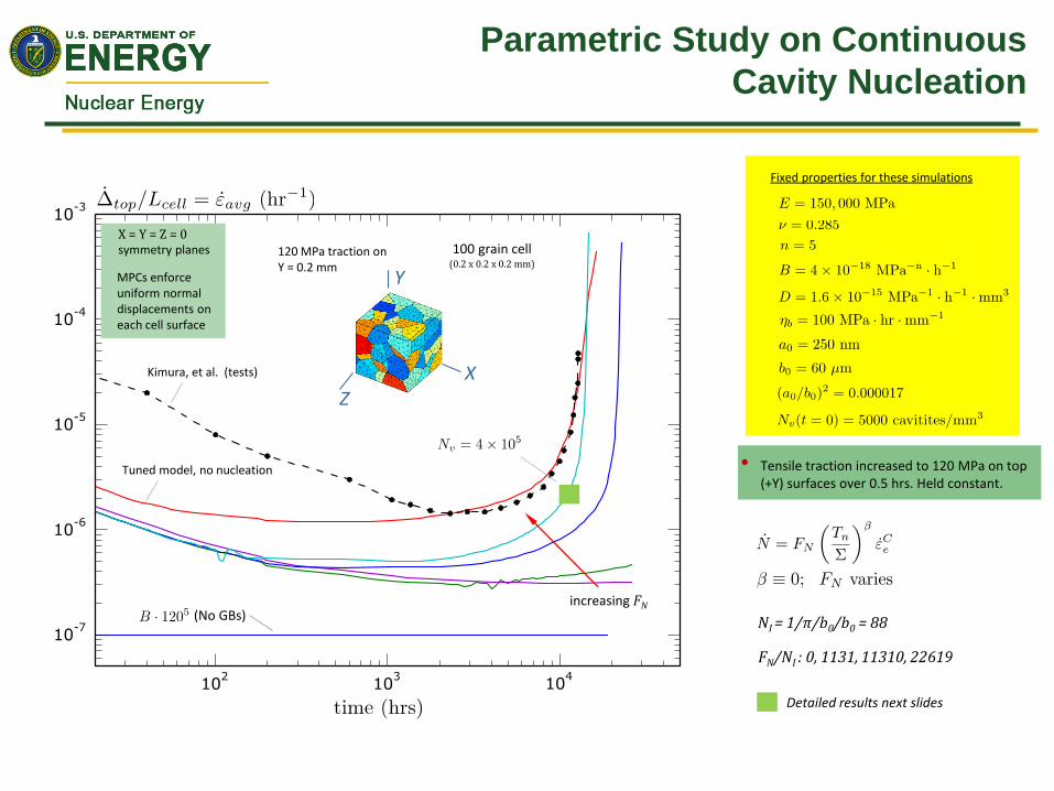
Parametric Study on Continuous
Cavity Nucleation
• Tensile traction increased to 120 MPa on top (+Y) surfaces over 0.5 hrs. Held constant.
(No GBs)
Tuned model, no nucleation
increasing FN
FN/NI : 0, 1131, 11310, 22619
NI = 1/π/b0/b0 = 88
Fixed properties for these simulations
X
Y
Z
Detailed results next slides

Cavity Density Measurements
Measurements reveal clear evidence of cavity nucleation as function of increasing stress/strain levels from inside surface-to-notch root
Cavity size distributions also measured
Same order of magnitude of cavity density at location with same triaxiality as uniaxial creep rupture test (at lower temperature and shorter time)
Notch root
slices for μ-tomography to detect voids, reconstruction of volumes between slices
26,000 hrs at 575o C ~80% of rupture life
2 mm σθθ = 93 MPa
Cavity density (1/mm3) × 105
(Tuned) Norton FE Sol’n
y
z
x
Interiorgrains(nofacetsonsurfaceofcube)
y
z
x
0.2mmcube
0.4mmcube
pressure + axial load
Measured cavity densities @ 26,000 h Creep strain 10% at root
~Gr91 w/ 1% W
Summary
The interaction of cavity nucleation, growth and coalescence process with grain
boundary sliding, and the effect of grain boundary orientation dependence have
been extensively studied using the cell model
Implementation of the crystal plasticity model and optimization of model
parameters are ongoing
The integration of the crystal plasticity model and grain boundary modeling has
begun

THANK YOU