The Cernavoda bridge - FREYSSINET · The Cernavoda bridge SEPTEMBER/DECEMBER 2001 ... bulletin...
24
reyssinet Romania The Cernavoda bridge SEPTEMBER/DECEMBER 2001 - No. 212
Transcript of The Cernavoda bridge - FREYSSINET · The Cernavoda bridge SEPTEMBER/DECEMBER 2001 ... bulletin...

reyssinet
Romania
The Cernavodabridge
SEPTEMBER/DECEMBER 2001 - No. 212
GB 212 couverture et 4e OK 4/12/01 9:15 Page 3
Co
nte
nts
Contents
2Freyssinet magazine September/December 2001 - No. 212
ARGENTINAFreyssinet-Tierra Armada S.A.Buenos AiresPhone: (54.11) 43 72 72 91Fax: (54.11) 43 72 51 79
BRAZILSTUP Premoldados Ltda São PauloPhone: (55.11) 3873 2734Fax: (55.11) 3672 8502
Freyssinet LtdaRio de JaneiroPhone: (55.21) 2221 8500Fax: (55.21) 3852 7926
Terra Armada LtdaRio de JaneiroPhone: (55.21) 2233 7353Fax: (55.21) 2263 4842
CANADAReinforced Earth Company LtdOntarioPhone: (1.905) 564 08 96Fax: (1.905) 564 26 09
COLOMBIASTUP de ColombiaBogotaPhone: (57.1)257 41 03Fax: (57.1) 610 38 98
Tierra ArmadaBogotaPhone: (57.1) 236 37 86Fax: (57.1) 610 38 98
EL SALVADORFessic S.A. de C.V. La LibertadPhone: (503) 2 78 07 55Fax: (503) 2 78 04 45
GUATEMALAPresforzados Técnicos S.A.Guatemala CityPhone: (502) 232 96 59Fax: (502) 250 01 50
MEXICOFreyssinet de México S.A. de C.V.Mexico D.F.Phone: (52) 5250 70 00Fax: (52) 5255 01 65
Tierra Armada S.A. de C.V.México D.F.Phone: (52) 5254 54 00Fax: (52) 5254 86 65
UNITED STATESFreyssinet LLC Chantilly, VA Phone: (1.703) 378 25 00Fax: (1.703) 378 27 00
Menard LLCVienna, VA Phone: (1.703) 821 10 54Fax: (1.703) 821 14 79
The Reinforced Earth CompanyVienna, VA Phone: (1.703) 821 11 75Fax: (1.703) 821 18 15
VENEZUELATierra Armada CaCaracasPhone: (58.212) 266 47 21Fax: (58.212) 267 14 23
BELGIUMFreyssinet Belgium N.V.VilvoordePhone: (32.2) 252 07 40Fax: (32.2) 252 24 43
Terre Armée Belgium VilvoordePhone: (32.2) 252 43 24Fax: (32.2) 252 24 43
DENMARKA/S SkandinaviskSpaendbetonVaerlosePhone: (45.44) 48 08 25Fax: (45.44) 48 12 45
FINLANDOY Jannibetoni ABVaerlose
FRANCEFreyssinet International & CieVélizyPhone: (33.1) 46 01 84 84Fax: (33.1) 46 01 85 85
Freyssinet FranceVélizyPhone: (33.1) 46 01 84 84Fax: (33.1) 46 01 85 85
PPCSaint-RémyPhone: (33.3) 85 42 15 15Fax: (33.3) 85 42 15 10
Ménard SoltraitementNozayPhone: (33.1) 69 01 37 38Fax: (33.1) 69 01 75 05
FYROMFreyssinet BalkansSkopjePhone: (389.2) 118 549Fax: (389.2) 118 549
GERMANYSBT Brückentechnik GmbHPlüderhausenPhone: (49.7181) 99 00 0Fax: (49.7181) 99 00 66
Bewehrte Erde GmbHPlüderhausenPhone: (49.7181) 99 00 70Fax: (49.7181) 99 00 75
GREECEFreyssinet Ellas S.A.AthènesPhone: (30.1) 69 29 419Fax: (30.1) 69 14 339
FredraAthènesPhone: (30.1) 60 20 500Fax: (30.1) 69 14 339
HUNGARYPannon Freyssinet KftBudapestPhone: (36.1) 466 90 04Fax: (36.1) 209 15 10
IRELANDReinforced Earth Co.KildarePhone: (353) 4543 10 88Fax: (353) 4543 31 45
ITALYFreyssinet Italia S.r.l.RomaPhone: (39.06) 418 771Fax: (39.06) 418 77201
Freyssinet Italia S.r.l.MilanPhone: (39.02) 895 402 76Fax: (39.02) 895 404 46
Terra Armata S.p.A.RomaPhone: (39.06) 418 771Fax: (39.06) 418 77200
NETHERLANDSFreyssinet Nederland B.V.WaddinxveenPhone: (31.18) 26 30 888Fax: (31.18) 26 30 152
Terre Armée B.V.BredaPhone: (31.76) 531 93 32Fax: (31.76) 531 99 43
NORWAYA/S Skandinavisk Spennbeton SnarøyaPhone: (47.67) 53 91 74
POLANDFreyssinet Polska Sp. Z o.o.MilanòwekPhone: (48.22) 792 13 86Fax: (48.22) 724 68 93
PORTUGALArmol-Freyssinet S.A.LisbonPhone: (351.21) 716 1675Fax: (351.21) 716 4051
Terra Armada LtdaLisbonPhone: (351.21) 716 1675Fax: (351.21) 716 4051
ROMANIAFreyrom S.A.BucarestPhone: (40.1) 220 35 50Fax: (40.1) 220 45 41
SPAINFreyssinet S.A.MadridPhone: (34.91) 323 95 50Fax: (34.91) 323 95 51
Freyssinet S.A.BarcelonaPhone: (34.93) 226 44 60Fax: (34.93) 226 59 98
Tierra Armada S.A.MadridPhone: (34.91) 323 95 00Fax: (34.91) 323 95 11
SWEDENAB Skandinavisk Spaennbeton MalmöPhone: (46.40) 98 14 00
SWITZERLANDFreyssinet S.A. MoudonPhone: (41.21) 905 48 02Fax: (41.21) 905 11 01
EUROPE
Freyssinet Magazine, 1 bis, rue du Petit-Clamart 78148 Vélizy Cedex – France. Tel.: 01 46 01 84 21. Fax: 01 46 01 86 86.Internet: www.freyssinet.comPublication manager: Isabelle Pessiot. Project leader: Stéphane Tourneur. Contributed to this issue: Can Aral, SomnathBiswas, Helen Blaton, Mischa Berntsson, Gianluigi Bregoli, Bill Brockbank, Laure Céleste, Stéphane Cognon, PhilippeCrignon, Manos Dimitripoulos, Stéphane Faure, Vladimir Filic, Jean-Philippe Fuzier, Yannick Garnier, Francis Geraint, DianeGriffiths, Dominique Jullienne, Sonia Kavyrchine, Likhasit kittisatra, Roger Lacroix, Jacky Leboeuf, Salvador Lorente, PaulMcBarron, Yvonne McDonald, Sylviane Mullenberg, Patrick Nagle, Susana Penas, Tomas Palomares, Jean-MichelRomagny, K. Thon. Artistic management: Antoine Depoid. Layout: Grafik Tribu. Translation: Netword. Editorial secre-tariat: Nathalie Laville. Photos: Francis Vigouroux, stt, Freyssinet photo library. Cover page: The Cernavoda bridge, photoStéphane Tourneur. Photo-engraving: Trameway/Grafik Tribu. Printing: SIO.
TURKEYFreysasIstanbulPhone: (90.216) 349 87 75 Fax: (90.216) 349 63 75
Reinforced Earth Company AIS IstanbulPhone: (90.216) 492 8424Fax: (90.216) 492 3306
UNITED KINGDOMFreyssinet LtdTelfordPhone: (44) 1952 201 901Fax: (44) 1952 201 753
Reinforced Earth Company LtdTelfordPhone: (44) 1952 201 901Fax: (44) 1952 201 753
AFRICAEGYPTFreyssinet EgyptGisaPhone: (20 2) 303 69 95Fax: (20 2) 345 52 37
SOUTH AFRICA
Freyssinet POSTEN (Pty) LtdOlifantsfonteinPhone: (27.11) 316 21 74Fax: (27.11) 316 29 18
Reinforced Earth Pty LtdJohannesburgPhone: (27.11) 726 6180Fax: (27.11) 726 5908
Although Freyssinet makes every effort to ensure that the information that it provides is as correct as possible, the editors,employees and agents cannot guarantee the results or be responsible for them in any way.
AMERICA
United K
AshfiBridgstrenp. 12
South A
Newpropp. 2
Interview
EnviWhap. 4
France
Solid grouting at Nice airportp. 20
Italie
The Mesp. 1
Bolivia
A viaduct in theAndesp. 14
Canada
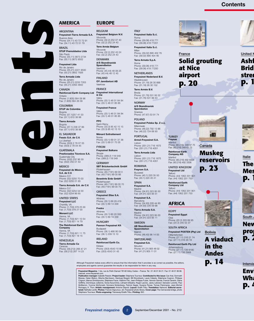
Muskeg reservoirsp. 23
GB 212 magazine new OK 4/12/01 9:02 Page 1

Contents
3Freyssinet magazine September/December 2001 - No. 212
ASIA
HONG KONGFreyssinet Hong Kong LtdKowloon TongPhone: (852) 27 94 03 22Fax: (852) 23 38 32 64
Reinforced Earth Pacific LtdKowloonPhone: (852) 27 823 163Fax: (852) 23 325 521
INDIATAI Aimil joint ventureNew DelhiPhone: (91.11) 695 00 01Fax: (91.11) 695 00 11
INDONESIAPT Freyssinet TotalTechnologyJakartaPhone: (62.21) 830 02 22Fax: (62.21) 830 98 41
JAPANF.K.K. TokyoPhone: (81.3) 35 71 86 51Fax: (81.3) 35 74 07 10
Terre Armée KK.TokyoPhone: (81) 427 22 1134Fax: (81) 427 22 1134
KUWAITFreyssinet International et CieSafatPhone: (965) 571 49 74Fax: (965) 573 57 48
MALAYSIAFreyssinet PSC (M) Sdn BhdKuala LumpurPhone: (60.3) 79 82 85 99Fax: (60.3) 79 81 55 30
Freyssinet AsiaKuala LumpurPhone: (60.3) 282 95 88/75 88/
05 88/96 88Fax: (60.3) 282 96 88
Freyssinet APTO (M) Sdn BhdKuala LumpurPhone: (60.3) 2 282 95 88Fax: (60.3) 2 282 96 88
OCEANIA
AUSTRALIAAustress Freyssinet Pty LtdSydneyPhone: (61.2) 9674 40 44Fax: (61.2) 9674 59 67
Austress Freyssinet (VIC)Pty LtdMelbournPhone: (61.3) 9326 58 85Fax: (61.3) 9326 89 96
Reinforced Earth Pty LtdSydneyPhone: (61.2) 9910 9910Fax: (61.2) 9910 9999
NEW-ZELANDReinforced Earth LtdDruryPhone: (64) 9 294 92 86 Fax: (64) 9 294 92 87
Menard Geosystem Sdn BhdKuala LumpurPhone: (60.3) 5632 1581Fax: (60.3) 5632 1582
Reinforced Earth ManagementKuala LumpurPhone: (60.3) 6274 6162Fax: (60.3) 6274 7212
PHILIPPINES Freyssinet Philippines S.A. Quezon CityPhone: (63.2) 921 3789 Fax: (63.2) 921 1223
SINGAPOREPSC Freyssinet (S) Pte LtdSingaporePhone: (65) 272 96 97Fax: (65) 272 38 80
Reinforced Earth (S.E.A.) Pte LtdSingaporePhone: (65) 272 00 35Fax: (65) 276 93 53
SOUTH KOREAFreyssinet Korea Co, LtdSeoulPhone: (82.2) 515 41 82Fax: (82.2) 515 41 85
Sangjee Menard Co LtdSeoulPhone: (82.2) 587 9286Fax: (82.2) 587 9285
TAIWAN Freyssinet Taiwan EngineeringCo, LtdTaipei Phone: (886.2) 274 702 77Fax: (886.2) 276 650 58
THAILANDFreyssinet Thailand LtdBangkokPhone: (662) 266 6088Fax: (662) 266 6091
UNITED ARAB EMIRATESFreyssinet (Middle-East) LLCAbou DhabiPhone: (971) 2 445 88 18Fax: (971) 2 445 88 16
VIETNAMFreyssinet International et CieHanoiPhone: (84.4) 826 14 16Fax: (84.4) 826 11 18
Freyssinet International et CieHo Chi Minh-CityPhone: (84.8) 829 92 28/29 31 09Fax: (84.8) 822 35 08
Romania
Putting theCernavodabridge into
positionp. 8
Malaysia
Cable stayed platform at
Sungai Teripp. 13
Kingdom
field ge ngthening2
India
Constructionof accessrampsp. 15
Thailand
Soil consolidation
in Bangkokp. 21
Singapore
Strengtheningof Mayten
buildingp. 23
Thailand
Rattathibetbridgep. 15
Africa
w minep systems 22
Australia
Innovative solution for restaurant
foundationsp. 18
ew
ironment: at is the answer?4
new ssina stadium16
GB 212 magazine new OK 4/12/01 9:02 Page 2

Interview
4Freyssinet magazine September/December 2001 - No. 212
FM: Is environment a passing phe-nomenon or have we always beenconcerned about it?
H.-U. L: In Germany, the environment is anextremely serious and very political subject.People might see it as a passing phenomenon, butin fact there is nothing new about it. Lookingback in the past, we can see that there has alwaysbeen close interaction between construction andthe environment. In 1757, a German foresternamed Carl Von Carlowitz suggested to organizemanagement of forests from which the wood wasused for construction, and he argued for a betterequilibrium in the use of materials. At the Rio deJaneiro Conference in 1992, the SIA (SwissSociety of Engineers and Architects) bulletinreported an increase in the number of articlesdealing with environment and its consequenceson the construction industry. Commission 3 atthe fib conference in Berlin, responsible for envi-ronment and materials, considered three majorthemes, namely protection of man against envi-ronment, harmony between structures and envi-ronment, and the choice fot the use of materials.We chose the environment topic because a lot ofinterest is paid to it at the moment and it con-cerns construction contractors.People are particularly interested in environmentnow for two reasons - industrialisation of coun-tries and politics. Politics always plays a veryimportant role that is often difficult to reconcilewith the interests of construction contractors.Thus the earliest laws on environment weredeveloped in Germany and Japan, and have nowspread throughout the world.
Environment: What is the answer?Today, environment as a concept is inextricably linked with the constructionand civil engineering trades. For this reason, the fib (fédération internationaledu béton) decided to focus on the subject "concrete and environment" on the occasion of the Berlin symposium held on 2-5 October 2001.Questions asked to Hans-Ulrich Litzner, general representative of deutscher Beton- und Bautechnik-Verein E.V. and event organizer.
What does this concept include?
Three elements have to be considered when talk-ing about environment, namely economy, ecolo-gy (the balance between nature and structure,particularly in terms of energy consumption)and social. The social aspect is undoubtedly themost important but is also the most difficult todefine. The environment guide published byGerman authorities illustrates this difficulty verywell when it asks "is it necessary or justified tobuild"? Because every construction needs to beaccepted by public opinion. In this respect, aes-thetics and environment are two complementaryaspects because the public will not accept struc-tures unless they blend well into the environ-ment. Nowadays, we are in a contradictory situ-ation. People no longer accept the constructionof infrastructures, but they demand easier accesseverywhere.
Must the environment be an element of a project?
The environment is a controlling factor, both forthe choice of materials and construction meth-ods. Although there are not yet any contractsbased strictly on respecting the environment,there are requirements about choices of materi-als to be used for the construction of roads, tun-nels and buildings. Many participants in the fibsymposium discussed subjects related to thechoice of materials and execution of work. Theyshowed that environment has a direct influenceon construction methods. Self-compactingconcrete is a good example because it avoids
Viewpoint
Hans-Ulrich Litzner, general dele-gate of the Deutscher Beton- undBautechnik-Verein E.V. associationcreated in 1898 and organizer of the fib said "We chose environmentas main topic because it is currentstate and it concerns constructioncontractors".
Sustainability: is developmentthat meets the needs of the presentwithout compromising the abilityof future generations to meet theirown needs[ [
GB 212 magazine new OK 4/12/01 9:02 Page 3

Interview
5Freyssinet magazine September/December 2001 - No. 212
the need to compact concrete and conse-quently the use of large and noisy machines.Although at the moment large projects haveto stop between 8:00 and 9:00 every evening,the advent of new material such as self-com-pacting concrete and new construction meth-ods that are kinder towards environmentcould affect works organisation.
Does the environment imply durability?
Durability is the keyword of the fib commis-sion 3. We are working to create modelsbased on limit state studies, to help predictaging of a building after fifty years, or abridge or tunnel after a hundred years and tomeasure concrete deterioration and micro-cracking. These models will help us to designstructures in the future. This activity is veryadvanced in Japan and is one of the fib'smain lines of scientific research. For exam-ple, consider the Westerschelde tunnel inthe Netherlands, for which the client hadspecified a life of a hundred years. The onlyway to achieve this was to use an empiricalapproach, using models and high perfor-mance materials. In short, we are more andmore willing to make a commitment aboutthe life of a project. This is well illustrated instandard EN1990 that contains a structuresdesign table showing the safe life of a struc-ture as a function of the loads that it sup-ports.The fib is developing more general modelsthat will be applicable within about ten years.We also prefer to use the word « sustainabil-ity » than durability. The word is not newsince Carl Von Carlowitz had already used it,but many people do not understand it. Yet, itencompasses the concept of environmentincluding social criteria. It means a longterm study to guarantee a high quality lifestyle to future generations.
Should the environment be stan-dardized or should a quality label becreated?
The environment cannot be standardized.It is only possible to standardize materialsand the use of these materials. On theother hand, as a result of computer sys-tems, we are able to measure the integra-tion of a structure in its environment andthus encourage debate, which is veryimportant, and necessary because the con-s t r u c t i o n m o d i f i e s t h e l a n d s c a p e .Therefore, we have to attempt to find a bal-ance between quality, economy and theenvironment.
Is construction the only businessaffected by the environment?
We cannot limit the concept of the environ-ment to new structures alone. Energy savingprovides a specific example. In Germany,70% of all energy is used to heat buildingsdespite strict regulations fixed after 1973. Inthis case, protection of environment is relat-ed to air quality and therefore to lower ener-gy consumption. The concept of the «three-liter car» in the automobile sector has nowbeen applied to buildings, with the objectivebeing to reach a structure consuming 30 kWper square meter a year, derived from allenergy sources - persons, computers, solarradiation, etc.Bridge repairs must also take the environmentinto account. Structures strengthening byadjustable and replaceable external post-ten-sioning tendons falls under the same logic.
Are we moving towards a mainte-nance market?
Not for buildings. The client should deter-mine the life of his building and engineersshould find materials necessary to guaranteesafety for this period, like what is alreadydone in agriculture. With this approach,everything (safety requirements, duration) ismore modest so that structures can berenewed continuously.This may seem surprising, but choice ofmaterials is dictated by their life. In short,economy and cost effectiveness are the over-riding factors.
What are the main conclusions ofthe fib symposium?The fib has to consider technical aspects related toenvironment and to develop models that can beused to predict aging of structures and a more gen-eral model that will serve as a basis for debates onthe environment and «sustainability». In thisSymposium, we realized that problems related tothe environment are similar in all countries in theworld, although at different levels. We becameaware that in the future, we would need to orga-nize a debate with everyone involved in the con-struction industry, to find something in commonbetween the different environment policies in forcethroughout the world.
"Aesthetics and the environment are two complementary aspects because public opinion willnot accept structures unless they blend well into the environment."The Normandy bridge is an excellent illustration of this.
Professor Joost Walraven, President of the fib,handed over the Merit Medal awarded by the fibto Jean-Philippe Fuzier (in photo), the StructureScientific Director of the Freyssinet Group, andDieter Jungwirth for outstanding contributions tostructural concrete and to fib.
GB 212 magazine new OK 4/12/01 9:02 Page 4
France-Germany
Pierre-Pflimlin bridge
Turkey Canada
Construction of a digesterFreysas has been awarded subcontractingservices for the prestressing works of 6 digester tanks to be constructedwithin the scope of Adana Waste WaterTreatment Plant.Freysas participated in many similarprojects such as Ankara (1995), Gaziantep(1998), and Denizli (2000) Waste WaterTreatment Plant constructions.After a logistic preparation and materialprocurement phase, the site installationwork started in July. The six digester tanks are 22 m high and have a diameterof 21 m.A total of 960 Freyssinet 12K15 anchors,246 tonnes of prestressing tendons and 16,800 m of corrugated ducts will be manufactured and installed.
Freysas built the first post-tensioned silo in Adana in year 1995. The projectincluding a 91 m high and 22.90 mdiameter silo, has drawn attention to the cement industry because of materialand cost savings brought intoinvestment decisions.Many cement producers decided toemploy post-tensioning for siloconstructions in their new investmentsafter the striking advantagesdemonstrated by this major project.This new era created by Freysas ,which was an important milestone in modern engineering in Turkey, hasnow been entered with the successfulcompletion of this new project.The Ünye cement silo has a storage capacity of 22,000 tons of raw material.The detailed study of applications made by Freysas and the excellentstructural behaviour of the silo in service demonstrated that post-tensioning was perfectly feasible in Turkey.
In brief
Freyssinet magazine 6 September/December 2001 - No. 212
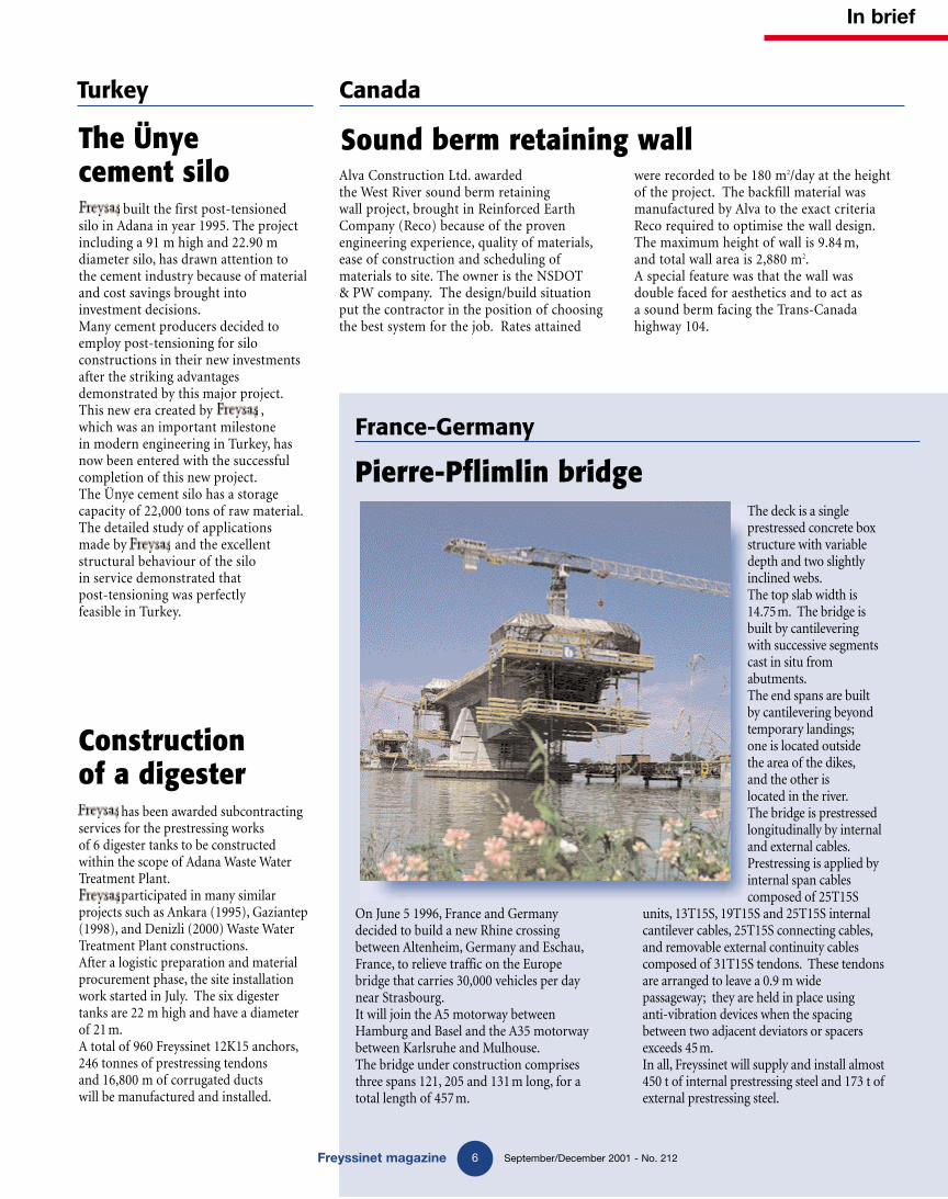
On June 5 1996, France and Germanydecided to build a new Rhine crossingbetween Altenheim, Germany and Eschau,France, to relieve traffic on the Europebridge that carries 30,000 vehicles per daynear Strasbourg.It will join the A5 motorway betweenHamburg and Basel and the A35 motorwaybetween Karlsruhe and Mulhouse.The bridge under construction comprisesthree spans 121, 205 and 131 m long, for atotal length of 457 m.
The deck is a singleprestressed concrete boxstructure with variabledepth and two slightlyinclined webs.The top slab width is14.75m. The bridge isbuilt by cantilevering with successive segmentscast in situ fromabutments.The end spans are built by cantilevering beyondtemporary landings;one is located outside the area of the dikes,and the other is located in the river.The bridge is prestressedlongitudinally by internaland external cables.Prestressing is applied byinternal span cablescomposed of 25T15S
units, 13T15S, 19T15S and 25T15S internalcantilever cables, 25T15S connecting cables,and removable external continuity cablescomposed of 31T15S tendons. These tendonsare arranged to leave a 0.9 m widepassageway; they are held in place using anti-vibration devices when the spacingbetween two adjacent deviators or spacersexceeds 45m.In all, Freyssinet will supply and install almost450 t of internal prestressing steel and 173 t ofexternal prestressing steel.
Alva Construction Ltd. awarded the West River sound berm retaining wall project, brought in Reinforced EarthCompany (Reco) because of the proven engineering experience, quality of materials,ease of construction and scheduling ofmaterials to site. The owner is the NSDOT & PW company. The design/build situationput the contractor in the position of choosingthe best system for the job. Rates attained
were recorded to be 180 m2/day at the heightof the project. The backfill material was manufactured by Alva to the exact criteriaReco required to optimise the wall design.The maximum height of wall is 9.84 m,and total wall area is 2,880 m2.A special feature was that the wall was double faced for aesthetics and to act as a sound berm facing the Trans-Canada highway 104.
The Ünye cement silo
Sound berm retaining wall
GB 212 magazine new OK 4/12/01 9:02 Page 6

In brief
7 September/December 2001 - No. 212Freyssinet magazine
Tierra Armada SA has just finished con-struction of the TechSpan® arches in Santa Cruz on Tenerife island.These structures form part of the con-struction of a low interchange between the TF5 motorway from the north and the TF1 motorway from the south, and comprise three segments - lines 10 and 13 each
carrying one traffic lane and line 01 that carries two traffic lanes separated by a New Jersey barrier. The structures are precast concrete arches that allow very small radii in plan. The entry andexit segments to TechSpan® arches arecomposed of precast spandrels associated with precast lateral retaining walls.The tunnels for lines 10 and 13 are respectively 90.2 m and 135.4 m long, and each tunnel is 3.5 m wide and 5.5 m high (outside dimensions8.5 m wide and 5.97 m high). The line 01tunnel is the longest at 421.3 m, and itsdimensions are 10.5 m wide and 5.5 m high (outside dimensions 13.9 m wide and7.6 m high). The depth of backfill abovethe keystone is 1.5 m for the first two tun-nels and 1.6 m for the second tunnel.The client for the work was the Ministry of Public Works, and the main contractorwas the TF-5 Group.
Spain
Chumberras interchange TF-5
Greece
Fruzi bridgeFruzi bridge is part of a new highway, connectingAgios Nikolaos and Ierapetra. It is closeto Pahia Amos on the North-East side of Crete.The client is the Ministry of Public Works, andthe main contractor is Ergokat SA. It is a 3-spanprestressed box girder bridge, 159.3 m long and13.5 m wide.It was built using the cast in situ cantilevermethod of construction and consists of a 71.30mmain span and two 44 m access spans.The structure is supported on two abutmentsand two intermediate piers, the heights of which are 45 and 35m respectively. Freyssinet Ellas SA has been appointed to supply and install the prestressing and supply the elastomericbearings. Both cantilever and continuity tendonsare being used. These are 19K15 tendons, from31m to 63.2m long. The work is due to becompleted by the end of October 2001. Anotherbridge was built as part of the same project toconnect the town of Agios Nikolaos to the smaller town of Lerapetra, with FreyssinetEllas SA being appointed as specialist contractor for the prestressing work. This is a 2-span 74m long and 13.50m wide prestressedbox girder bridge. It was also built using the castin situ cantilever construction method and is supported on two abutments and a 20m highintermediate pier. Prestressing includescantilever and continuity tendons.
Freyssinet Belgium is participating in the construction of a car park inLouvain, Belgium.The original projectdesign used precastelements. During construction of thework, it was foundthat the foundationscould not resist the car park roofloads, and therefore it was decided tobuild a concrete topslab with 2-dimensional prestressingusing cables composed of 1F15 unbond-ed strands. The slab consists of twomain parts; firstly, a small entry tunnel,secondly the car park itself. The carpark itself is divided into two parts connected together by couplers; one of the phases was opened to the public
in mid-August 2001.The architectural work was done by theDe Gregorio & Partner Company withAldo Rossi Associati, the general designwas done by Arcade, and the prestress-ing design was awarded to Gamaco byFreyssinet Belgium. The main contrac-tor was Van Roey.
Belgium
Car park slab in Louvain
FranceAsbestos removaloperation
The MTSCompany (the Freyssinet Group) has justcompleted aproject aimingto removeasbestos fromthe room housing theflight simulatorbelonging to its client,Air France.
MTS treated a total of 300 m2 ofthermoplastic tiles and shot blasted the glue containing asbestos.
GB 212 magazine new OK 4/12/01 9:02 Page 7

Romania
Main characteristics:
• Bridge length: 172.5 m.
• Roadway width: 7.8 m.
• Sidewalk width: 2.25 m.
• Total structure weight: 1,325 t.
• Number of stay cables: 56.
• Rotation on boom: 34 m (4 h 30).
• Rotation on barge: 250 m (6 h).
• Pushing: 25 m (7 h).
dige
st
GB 212 magazine new OK 4/12/01 9:02 Page 8

Romania
9Freyssinet magazine September/December 2001 - No. 212
Freyssinet, in co-oper-ation with its romaniansubsidiary, Freyrom, hasbeen appointed toperform the rotation
and pushing operations for thenew bridge over the canal joiningthe Danube and the Black Sea inCernavoda.
digest
Putting theCernavoda bridgeinto position
Construction methods
This bridge has a modern architecturaland structural design, and is also distinctive by the innovative methods used for construction.
GB 212 magazine new OK 4/12/01 9:02 Page 9

T he urban district of Cernavoda (60,000inhabitants) stretches along the canalbetween the Danube and the Black sea
(Canalul Dunare Marea Neagra), 190 km to the east of Bucharest. This city is a strategicRomanian site since the country's nuclear reac-tors are located in it. It now has a new roadbridge that crosses the canal to provide themain access to the town and its railway stationon the opposite bank. With its red arch, itswhite stay cables and itsstructural slenderness,Cernavoda bridge is amodern art project inkeeping with the tra-dition of the majorRomanian steel bridgesbuilt at the end of theXIXth century.The bridge is an all-steelstructure made of a decksupported by two longitudinal girders, 15bridge segments and a multiple Nielsen typearch culminating at a height of 28 m above the road surface. When in its final position, itwill be about thirty meters above the canal andwill allow navigation to conform withEuropean standards. It is supported on a 20 mhigh rectangular pier founded on 1.5 m diam-eter piles with lengths varying from 30 to 45 m,on each side of the canal. The length of thebridge is 172.5 m and its total weight is 1,325 t,its road surface is 7.8 m wide and it has two2.25 m wide sidewalks. The bridge has a mod-ern architectural and structural design, and isalso distintive by the innovative methods usedfor its construction.
Rotation on barge
The deck is built on the left bank parallel to the Danube canal. There are 56 12HD15 typestay cables (28 on each side) with individually
protected strands, inserted in a white HDPEsheath, and inclined at 60°. The method pro-posed by Freyssinet and its Romanian sub-sidiary Freyrom to bring the bridge into linewith the access spans, consists in rotating thedeck supported on three hydraulic jacks on abarge floating on the Danube canal supportingthe front of the deck, and on a pivot at the backof the structure that acts as an axis of rotation.The operation includes three main phases,namely shifting the deck for 34 m on land,rotating it on the river for 250 m, and translat-ing it by 25 m.The first step is to shift the structure usingTP50 jacks firstly on curved concrete beams,and then on a steel boom. It is then loaded ona 50 m long 20 m wide barge from which bal-last is progressively removed to compensate forthe weight of the deck. Three T15 type tendons,anchored in concrete foundations on the oppo-site bank (right bank), operate in turn to pullthe structure sideways using SC2 1000 rotationjacks equipped with SL12, fitted on steel beamsat the front of the deck; a fourth tendon acts asa holding cable.Rotation is a difficult and painstaking opera-tion that must allow for many natural parame-ters, including a high recurrent wind factor.
Rotation is applied in steps of1 m until the final position isreached. The rotation deviceis then removed to leave roomfor a translation system simi-lar to the system used in thefirst phase.
A translation of 1325 tons
Two pairs of TP50 pushing jacks each with acapacity of 25 t are fixed to longitudinal con-crete beams at the back of the bridge. The jacksare fitted with blocking shoes and move for-wards along two lateral concrete beams actingas racks. The structure is supported on slidingsaddles equipped with a coating composed of apolished stainless steel plate sliding on rein-forced neoprene pads coated with a sheet ofTeflon, to facilitate the different pushing oper-ations. 600 t hydraulic jacks are located facingthe four bearings on the underside. Translationis applied on both sides of the deck simultane-ously in 0.35 to 0.4 m steps. In the first phase,the deck-barge assembly is pushed for a dis-tance of about ten meters until the front noseof the boom lands on the temporary bearingson the left bank pier; the deck can then bepushed about fifteen meters up to the abut-ment. As pushing continues, the loads of thedeck are transferred to the temporary bearings,so that ballast has to be added to the barge to
Freyssinet magazine September/December 2001 - No. 212
Romania
10
The structure is in keeping with
the tradition of largenineteenth century
Romanian steel bridges.
GB 212 magazine new OK 4/12/01 9:02 Page 10

keep the structure at a constant height abovethe water level. Freyssinet's teams and survey-ors use a computer system to closely monitorthis load transfer and the geometric position ofthe deck. The deck will be raised to its final ele-vation when pushing is complete.The final step in this project consists ofFreyrom's supply and installation of Tétron®bearings and road construction joints. Allequipments are manufactured in Romania, in aproduction unit located in Bucharest.
Participants
Client: SN Nuclear Electrica.Engineer and main contractor: CCCF.Design: Eurometudes.Specialised contractor: Freyssinet,in co-operation with Freyrom.
Romania
11Freyssinet magazine September/December 2001 - No. 212
The bridge was pushed using two hydraulic jacks fixed to the back of the structure.
Shifting the deck on concrete beams.
Operation sequence.
Rotating the deck onto the bank.
Translating the bridge on a barge. Pushing the deck into final position.
Lifting into final position. Pushing the approach spans.
GB 212 magazine new OK 4/12/01 9:02 Page 11

12 September/December 2001 - No. 212Freyssinet magazine
Repair and strengthening
A shfield Bridge, near Rochdale inLancashire, carries Junction 21 slip-roads under the M62. The strength
of the bridge had been assessed as sub-stan-dard and instrumentation installed to allowremote monitoring of the structure’s responseto M62 traffic loads passing over it. A deci-sion was taken to strengthen the bridge andin early 2001 the contract was awarded toFreyssinet.Work consisted in installing steel props,which were subsequently stressed using flatjacks, relieving loads in the deck, thus allow-ing deck strengthening by a combination ofcarbon fibre and steel plate bonding. A totalof 43 props were installed using 305 x 305universal channels, approximately 3.3 m long.At the lower end the props sat on new rein-forced concrete corbels keyed into hydro-demolished pockets using resin anchoredstrengthening. At the top of the props thenew corbels could not be keyed into pocketsin the existing structure, so resin anchoredhigh-tensile post-tensioned bars were used tocomplement the additional resin anchoredstrengthening.215 T flat jacks sat between the top of theuniversal channels and the upper corbel. Thejacks were inflated using grout to perma-nently transfer load into the props and allowplate bonding to proceed. Steel plate bondingwas installed on the upper surface of thedeck at three locations in the M62 hardshoulder. Carbon fibre plate bonding wasinstalled at six locations on the deck beamsoffits. Both carbon fibre and steel platebonding were designed in-house byFreyssinet. Once jacking was complete thecolumns were encased in concrete; a high
strength self-compacting mix was generallyused, but the top 0.5 m of each column wasfinished off using spray concrete.Because of the pronounced curve of the sliproads, a temporary concrete barrier was usedon the outer radius during the constructionphase, replaced by a permanent concrete bar-rier at the end of the contract to protect thenew props. The confined space under thebridge and poor sight lines meant that thetraffic management scheme was supervisedusing a closed control monitor and a recoveryvehicle was on permanent standby.
Ashfield Bridgestrengthening
The transpennine motorway bridge is being renovated, making com-bined use of several reinforcing techniques.
United Kingdom
Participants
Client: Highways Agency.Engineer: Parkman.Main contractor: Freyssinet Ltd.
GB 212 magazine new OK 4/12/01 9:02 Page 12

13Freyssinet magazine September/December 2001 - No. 212
Construction
T he bridge deck is a platform supportingpipes, pumps and other equipment neces-sary to pump water and transport it to the
treatment plant. This deck is 80 m long and 15.2 mwide and is supported by stay cables anchored ina very narrow 18 m high tower located 36.2 mfrom the abutment, starting from the deck andcomprising two parallel A frames. The structurecantilevers 43.75 m from the tower center line.The back span consists of a 20 cm thick rein-forced concrete deck supported by two 45 m lon-gitudinal prestressing beams. It is fixed mono-lithically to the abutment and the foundation ofthe pier at the other end. The transverse pre-stressing beams are at a spacing of 3.1 m and aresupported by the two end beams. The front spanof the cantilevered composite deck includes a20 cm thick reinforced concrete slab supportedby two 35 m steel beams. These beams are con-nected to the longitudinal prestressing beams by40 mm diameter Macalloy bars. Transversebeams are supported on these beams at intervalsof 3.8 m. The front slab is composed of 13 cmthick precast panels on which a 70 mm concretelayer is laid on a 15.2 m by 36.1 m area.
Tower foundation under 10 m of water
The structure is supported by ten type 12H15or 19H15 stay cables, with five at the front andfive at the back, in two parallel planes. Thefixed upper anchors are embedded into the topof the tower and the lower anchors are con-nected to the longitudinal beams. TheFreyssinet system uses high strength galvanizedmonostrand tendons with seven HDPE coatedwires.
The most difficult task on this project was tomake the 2 m thick tower foundation under 10 m of water in a single pour of B 50 concrete.The high pressure exerted on the walls ofthe 12.4 m x 12.4 m cofferdam was resisted by waterproof sheet piles driven deep into the ground using a 3.2 t vibrating pile driver.The stay cables were installed and tension wasapplied at the same time as construction of thefront deck.
Participants
Client: Water Authority of Negeri Sembilan (JBANS).Engineer and main contractor: Salcon Berhad.Consultant: B.W. Perunding Sdn Bhd.Design: MM. Wong Boon Chong and Jurutera Perunding in association with Freyssinet APTO.Main subcontractor: Visage Engineering Sdn Bhd.Specialised contractor: Freyssinet PSC (M)SDN BD.
Cable stayed platformat Sungai Terip
Freyssinet PSC (M) Sdn Bhd is participating in the construction of a water intake platform for the Sungai Terip reservoir at Seremban,in Malaysia.
Malaysia
GB 212 magazine new OK 4/12/01 9:02 Page 13

14 September/December 2001 - No. 212
Bolivia
Freyssinet magazine
T he interocean network in South Americamust be improved in many countries,and particularly in Bolivia, to make it
practicable in all seasons. One of these roads,the "Bioceánica" (Two Oceans) between theCotapata and Santa Barbara districts, crossesthe Real Cordillera in the Andes at an altitude of 4,650 m and drops to 980 m above sea level over a distance of only 45 km. Due to the broken relief, 20% of this section is carried on bridges. The Bolivian National RoadsService has appointed the Andrade Gutiérrez,COPESA and Minerva asociados contractors tobuild this road. The work is supervised byConnal and Lahmeyer GmbH and Hidroservice.
Three continuous sections
The mountainous topography makes con-struction of this section very difficult, and par-ticularly the construction of a viaduct includedin the project. Admittedly it is dwarfed by the grandeur of the surrounding nature, but itnevertheless reveals man's genius in building.The bridge was designed and constructed byIngenieros Bolivianos, and consists of three con-tinuous spans; two are 30 m long with a con-stant cross-section, thus acting as a counter-weight to the 90 m main span. The viaduct isconstructed in successive cantilevers startingfrom the piers and working towards the center.Its height is variable and parabolic. The first
segments are 4.5 m high and the key segment is1.6 m high. Each span comprises fifteen 2.89 mlong segments with the 0.2 m key segment beingon the center of the road. This bridge is curvedin plan with a radius of 135 m, and has a tran-verse slope of 5.5% corresponding to a basicspeed of 40 km/h, and a longitudinal slope of1%.The cross-section of the superstructure is madeof a box with a single web. The bridge is 10.4 mwide and carries an 8.3 m wide road and two1.05 m wide pavements. The thickness of thetop flange is 0.24 m. The webs are 0.25 m thickand increase to 0.4 m to accommodate theFreyssinet prestressing anchors. The two websdiffer in height due to the curvature, supportingthe horizontal bottom flange over all sections with a thickness varying linearlyfrom 0.4 m at the bearing to 0.18 m at the keysegment.The entire post-tensioning is supplied andapplied by Freyssinet. The most highly stressedsection during the cantilever construction is onthe center line of the piers due to the bendingmoment. In order to respect the constructioncalendar for the segments (7 days), the concretemust have reached the strength of 25 MPa atthree days so that the prestressing force can betransferred to each segment.The bridge comprises two - 23 m and 28 m - highpiers with a constant rectangular cross-sectionand two webs. Each is supported on a concrete
foundation anchored on six 1.4 m diameter cir-cular piles. The abutments are supported onthree 1.4 m diameter piles with variable depthsto suit the ground. The diameter of all 18 pilesincreases to 2.4 m at their base.This project also includes bridges with I-girdersand hollow piers prestressed using the Freyssinetsystem.Apart from the prestressing work, Freyssinet'sservice includes the supply and installation offour high capacity bridge bearings (two for eachpier) and Freyssinet TECNISLID 3 GL typemechanical bearings used for the first time inBolivia. The structure must be completed at theend of the year 2002.
Prestressing
Freyssinet is carrying out prestressing work and is responsible for thesupply and installation of bridge equipment for one of the viaducts partof the “Bioceánica” road.
A viaduct in the Andes
GB 212 magazine new OK 4/12/01 9:02 Page 14

Freyssinet magazine September/December 2001 - No. 21215
Thailand
India
Construction of access ramps
Reinforced Earth® walls
In Delhi, the Public Works Department has chosen to builddecidedly modern bridges combining the prestressing and Reinforced Earth® technologies.
T he Public Works Department of the NCT(National Capital Territory) governmenthas decided to build four flyovers and four
subways in Delhi. These structures will be locat-ed at several intersections - the Ring Road andRao-Tula Ram Marg (Moti Bagh) intersection, theRing Road and Africa Avenue intersection, theOuter Ring Road and HR Sethi Marg (NehruPlace) intersection, and the Outer Ring Road -Savitri Cinema T-Junction.The flyovers were designed to be constructedusing state of the art technology in order to saveproject construction time, reduce pollution levels,produce minimal disruption to traffic and incon-
noise pollution levels. Three of these flyovers wereconstructed with a slope of 6%. A total of about7,500 m2 of Reinforced Earth® walls were success-fully designed and constructed. Design validationwas done by tests made in situ. These include:Evaluation of pullout resistance of the strips andinterface friction coefficient; Evaluation of fas-teners (lugs / tie-strip) connection strength andefficiency with precast concrete panels; Full-scaleimpact test on the New Jersey type crash barriersystem proposed for these projects, and an evalu-ation of the structural capacity of panels underdynamic loading conditions.
venience to commuters, and optimise superiorvalue engineering and aesthetics. The design of these flyovers is unique and they incorporate a number of features that are being used for the first time for flyovers in National CapitalTerritory of Delhi. These include the concept ofprestressed segmental construction for the mainbridge spans and the use of Reinforced Earth®technology for the approaches.The cruciform shaped Reinforced Earth® Panelshave a unique flute pattern design which was alsointegrated into the piers, drain covers and parapetfinishes. This design was also conceived to act asmultiple sound reflectors and thereby reduce
Freyssinet is participating in the construction of a bridge 30 km North of Bangkok in Nonthaburi province.
T he project consists of two 140 m pre-stressed concrete twin structures, builtusing the free cantilever technique.
Each comprises a 70 m main span with 3 mlong segments. The main piers are integralwith the superstructure that is supported on
pot-type bearings at the other piers.Freyssinet participated in the construction ofthe structures, and was responsible foranalysing the deformation for the precambercasting curve (development of a 2D comput-er model), supplying and installing the pre-
stressing (252 t of 12 and 19K15 tendons for I-girders and 130 t of 12K13 tendons forbalanced cantilevers) and for designing of formwork travellers and formwork of piersegments.
Rattathibet bridge
Prestressing
GB 212 magazine new OK 4/12/01 9:02 Page 15

Nowadays, Messina is an important har-bour city at the north-easternmost tip ofthe island of Sicily (270 000 inhabitants).
It is located in the midst of the Mediterranean,on the Straits of Messina separating the islandfrom the Italian mainland. The town's time ofglory was in ancient Greek times, and many wellpreserved examples of Greek architecture stilldot the surroundings. One of the most magnif-icent is undoubtedly the Taormina amphitheatre,built out of stone and earth, 40 km South ofMessina on a hillside overlooking the Ionian seatowards Etna.
An amphitheatre in the ancient style
When faced with the task of designing a new stadium for the city, the architects could notavoid referring to this magnificent old structure.Taking inspiration from construction methodsused in ancient times, they imagined anamphitheatre that would be an enormous semi-rectangular embankment with rounded cornersbacking onto a hillside on which concrete stepswould be arranged to accommodate the public,similar to what was done by Greek architects inthe IVth century before Christ, except that in theXXIst century, a stadium must also be accessibleto cars, be provided with safety escapes, rampsfor the handicapped, and all the other featuresrequired in modern times. An earth retainingsystem had to be designed to divide the earth
embankment into sections and cut passagewaysthrough it to support staircases and ramps. Theychose to use the Reinforced Earth® technique.This system ensured that the main constructionmaterial, also for the retaining walls, would stillbe soil, thus keeping the “classical design”approach. Terra Armata, member of theFreyssinet Group, had already participated in theconstruction of the road between the motorwayand the stadium six years earlier. It had then pre-pared the engineering project and supplied thematerials and technical assistance for the con-struction of four retaining walls (with a maxi-mum height of 12.5 m and a total surface area of3,150 m2). The designers' choice was made con-sidering the good results obtained by TerraArmata in this contract, in terms of design flexi-bility, cost reduction, speed, ease of constructionand strength of the completed structure.
Reinforced Earth® Structures
A total of about 3,000 m2 of Reinforced Earth® wallswere designed and are now being built. Twothree tiered vertical Reinforced Earth® walls(TerraClass™) were designed to cut passagewaysthrough the embankments on the east and westsides of the amphitheatre, this allows vehicles toaccess the site from outside the stadium. Thesewalls will also support access ramps, stairs andpart of the spectators' area.The East side wall has a maximum total height of 21.5 m for the three tiers. The height of the
The new Messina stadium
Reinforced Earth® Walls
16Freyssinet magazine September/December 2001 - No. 212
Italy
Terra Armata is participating in the construction of the new Messina stadium, a structure inspired by the construction and architecture of ancient roman amphitheatres.
GB 212 magazine new OK 4/12/01 9:02 Page 16

Freyssinet magazine September/December 2001 - No. 212
Italy
17
lower wall varies from 0.5 to 10.85 m and itstotal surface area is 780 m2.It supports the access ramp reserved for thehandicapped. The intermediate wall is 0.5 to7.5 m high and its total surface is 850 m2. Itsfront face has many angles to provide room forthe ramp turns. It also supports the stairs lead-ing to the spectators' seats. The maximumheight of the top wall is 6.2 m and its total sur-face is 124 m2.The maximum total height on the West side is20 m for the three tiers. The lower wall varies inheight from 0.5 to 7.5 m, and its total area is304 m2. The height of the intermediate wallvaries from 0.5 to 9 m, and its total area is470 m2. The maximum height of the top wall is5.8 m and its total surface is 110 m2. This struc-ture supports the spectators' area and provideslateral confinement to the earth embankment.Another smaller Reinforced Earth® wall (with a maximum height of 10 m) will support theV.I.P. area and will provide confinement to theearth embankment, thus facilitating access to thearea itself.
An innovative design
This is not a typical Reinforced Earth® project,such as a road retaining wall. It is an architec-tural project, and hundreds of Reinforced Earth®front panels had to be designed and precast withthe greatest care, in order to ensure the effectsand the minimum tolerances required by thearchitect.It was also necessary for Terra Armata's technicaldepartment to study and design dozens of con-struction details such as safety barriers, lightningposts, doors, etc. to be integrated into the project.The top walls of the East and West side structuresalso support the beams that carry the superstruc-ture where spectators will sit. These beams areapplied to the Reinforced Earth® structure as con-centrated loads (permanent load 6 tons/linearmeter, live load 5 tons/linear meter) as far as the topwall which was partly designed as an abutment.Terra Armata delivered a complete engineeringproject, including materials for wall construction; itis now providing engineering assistance on site anddesign advice until the completion of work.
Participants
Owner: town of Messina.Architect: Prof. Arch. Leonardo Urbani & Ass.Engineer: Ing. Giuseppe Rodriquez & Ass. - E.C.S.Geotechnical consultant: Prof. Ing. G. Umilta.Main Contractor: Joint Venture Astaldi S.p.A.-Costanzo S.p.A. - Versaci S.p.A.Specialised contractor: Terra Armata Italia.
Football stadium for the Oviedo club (Spain)The construction of the access roads to the new Carlos Tartiere football stadium in Oviedo (in the Asturies) involved the erection of a perimeter wall. This wallincludes two types of structures, one with continuous faces for a maximum heightof 9 m, the other divided into two parts with vertical faces for a maximum height of18 m. The total area of the walls is 3,718 m2. The second structure is composedof two walls up to 6 m high in the lower part and up to 12 m high in the upper part.This solution solved the problem of level difference between the two traffic laneswithout having to build a wall at the bottom of the embankment, and maintainingthe required aesthetic appearance.
ParticipantsOwner: Oviedo Town Hall.Main contractor: Dragados.Specialised contractor: Tierra Armada SA.
GB 212 magazine new OK 4/12/01 9:02 Page 17

Australia
18Freyssinet magazine September/December 2001 - No. 212
Innovative solutionfor the foundations of a restaurant
Geotechnics
Whereas the prospect of a restaurant on one of Sydney’s prime locations has unchallenged appeal, the realisation of this prospect set numerous challenges. Austress Freyssinet combined its specialist engineering skills with innovation and experience, so that with the co-operation and support of the Client, Project Manager, Architect and Engineering Consultants, this prospect became a reality.
T he Sydney Ports Corporation redevelop-ment required a 30 m by 12 m and 4.5deep basement for the restaurant to be
constructed within the confines of the oldoverseas passenger terminal building, wherethe natural ground water fluctuates with thetides over a range of 2 m, as a result of theclose proximity to the harbour.The site is on reclaimed land, underlain byold marine structures and wharves covered by random fills deposited over the past 200 yearsduring various phases of shoreline develop-ment, which in turn are underlain by alluvialdeposits with sandstone bedrock occurring ata depth of 17 m below ground level. The mat-ters were further complicated as the head-room was limited to 6 m and the presence ofexisting inground services, old piled founda-tions, footings and remnant basements.In addition, the loose and varied nature of thefill placed during the original construction ofthe Passenger Terminal in the 1960’s made the implementation of traditional cofferdammethods such as sheet piling, diaphragmwalling or battered slopes both technicallyand economically not viable.The presence of popular restaurants andtourist attractions of the Rocks, the clear har-
GB 212 magazine new OK 4/12/01 9:02 Page 18
19Freyssinet magazine September/December 2001 - No. 212
sive and more dangerous for the environment.The southern basement of the Sydney Covepassenger terminal was thus completed suc-cessfully, within allocated dead lines and with-in budget, thus demonstrating the excellence ofthe company's civil engineering activitiesthrough a wide range of design and construc-tion activities carried out in a very sensitivepublic environment. This application was sub-mitted for consideration for the EngineeringExcellence Awards on behalf of all AustressFreyssinet employees and everyone else whocontributed to the success of this project.
Participants
Client: Sydney Ports Corporation.Engineer: App Projects.Main contractor: Bovis Lend Lease.Architect: Bligh Voller Nield.Specialised subcontractor: Austress Freyssinet.
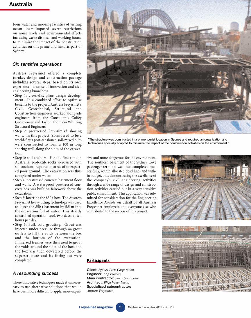
bour water and mooring facilities of visitingocean liners imposed severe restrictions on noise levels and environmental effectsincluding waste disposal and working hours,to minimize the impact of the constructionactivities on this prime and historic part ofSydney.
Six sensitive operations
Austress Freyssinet offered a completeturnkey design and construction packageincluding several steps, based on its ownexperience, its sense of innovation and civilengineering know how.• Step 1: cross-discipline design develop-
ment. In a combined effort to optimisebenefits to the project, Austress Freyssinet'sCivil, Geotechnical, Structural andConstruction engineers worked alongsideengineers from the Consultants CoffeyGeosciences and Taylor Thomson WhittingStructural Engineers.
• Step 2: prestressed Freyssimix® shoringwalls. In this project (considered to be aworld-first) post-tensioned soil-mixed pileswere constructed to form a 100 m longshoring wall along the sides of the excava-tion.
• Step 3: soil anchors. For the first time inAustralia, geotextile socks were used withsoil anchors, required in areas of unexpect-ed poor ground. The excavation was thuscompleted under water.
• Step 4: prestressed concrete basement floorand walls. A waterproof prestressed con-crete box was built on falsework above theexcavation.
• Step 5: lowering the 850 t box. The AustressFreyssinet heavy lifting technology was usedto lower the 850 t basement by 5.5 m intothe excavation full of water. This strictlycontrolled operation took two days, at tenhours per day.
• Step 6: Bulk void grouting. Grout wasinjected under pressure through 44 groutoutlets to fill the voids between the boxand the bottom of the excavation.Immersed tremies were then used to groutthe voids around the sides of the box, andthe box was then dewatered before thesuperstructure and its fitting-out werecompleted.
A resounding success
These innovative techniques made it unneces-sary to use alternative solutions that wouldhave been more difficult to apply, more expen-
Australia
"The structure was constructed in a prime tourist location in Sydney and required an organization andtechniques specially adapted to minimize the impact of the construction activities on the environment."
GB 212 magazine new OK 4/12/01 9:02 Page 19

France
20Freyssinet magazine September/December 2001 - No. 212
Solid grouting at Nice airport
Soil reinforcement
The Freyssinet South-East and Menard Soltraitement South-EastGroup has just performed a soil strengthening project by solid grouting on the access viaduct to Nice airport terminal 2.
C ampenon Bernard Méditerranée hasappointed the Freyssinet South-East andMenard Soltraitement South-East group to
apply solid grouting treatment to sand layers inwhich there was a risk of liquefaction in the case of an earthquake. This treatment was applied adja-cent to six piers and two abutments supporting the future access viaduct to Nice airport terminal 2.This treatment makes it possible to support thestructure on surface foundations.
Grids and boreholes
The depths varying from 15 to 25 m and the thick-nesses to be treated, varying from 3 to 7 m, weredetermined by Fondasol based on a comparisonbetween values measured in untouched soil (netlimiting pressure and SPT*) at the location of eachfoundation, and limit values for non-liquefactiondeduced from Ambraseys formula. This treatmentis obtained using primary and secondary boreholes
at the location of each foundation on regular 4 x 4 m to 5 x 5 m grids, extending beyondthe periphery by at least one grid line. Grouting isdone sequentially on the primary boreholes, firstlyaround the periphery in order to form a cage, andthen secondary boreholes and finally tertiary bore-holes if non-liquefaction criteria are not satisfied.Grouting parameters (grid, filling ratio, pressurestop criteria, etc.) were selected at the beginning ofthe work during two test plates on which pressuremeasurements and SPT tests were carried out. Thisproject was carried out over a two-month period,and includes a total of 6,000 m of boreholes and350 m3 of injected grout.
Monitoring and inspection means
The solid injection process selected for this projectconsists of forcing mortar into the subsoil at pres-sures varying from 4 to 7 MPa through tubing previ-ously driven into the ground by rotary percussion,
using sacrificial tools. Mortar is added from the bot-tom working up in 0.5 to 1 m passes starting fromthe bottom of the boreholes. With this type of treat-ment, internal quality control can be carried outcontinuously, and external quality control can bedone when the works are accepted. The internalinspection is done by real time monitoring; the digi-tal and graphic recorder installed on the drillingmachine indicates the main parameters (advancespeed, pressure on the tool, grouting pressure, etc.)during the drilling phase. This information is usedto identify correlations with the results from bore-holes made in previous investigations. The main filling parameters in the grouting phase, in otherwords the instantaneous flow, the accumulated flowper pass and the grouting pressure are recordedusing automatic pulse counters and manometersinstalled on the pump and at its output. A report isproduced for each foundation, containing records ofparameters and filling characteristics for each 1 msegment (volume added, injection pressure at end ofpass, etc.). The external check is done by Fondasolresponsible for geotechnical monitoring of thework; they carry out a series of pressure measure-ment boreholes and SPT tests under each treatedfoundation. These checks are used to ensure that theliquefaction potential is eliminated. The FreyssinetSouth-East geotechnical team and Menard Soltraite-ment (South-East branch), a subsidiary of theFreyssinet Group, have combined their know how,personnel and equipment resources (2 drillingmachines, 1 double piston pump, etc.) to carry outthis solid grouting work.
Participants
Client: Côte d’Azur Chamber of Commerce and IndustryMain contractor: Thalès (SODETEG).Specialised contractor: Freyssinet and MenardSoltraitement. Group
* Standard Penetration Test
GB 212 magazine new OK 4/12/01 9:02 Page 20

Thailand
21Freyssinet magazine September/December 2001 - No. 212
Soil consolidation in Bangkok
Vacuum® consolidation
The Menard Soltraitement Vacuum® consolidation solution was selected for the construction of a new electricity power station in Thailand.
E PEC (the electricity company) decided tobuild a 350 MW combined cycle power sta-tion to match the increasing demand for
electricity in Thailand. This power station builtby Alstom Power is located at the estuary of theChao Phraya river amongst several shrimp farms30 km south of Bangkok in the Gulf of Thailand,and is founded on 33 m long piles.Menard Soltraitement proposed a Vacuum® con-solidation solution to treat the clay under powerstation roads, so that the power station could beconstructed on very poor soils. Vacuum® con-solidation is more economic than the use ofpiles, and provides a means of causing early set-tlement of the order of several meters, leaving afew centimetres of residual settlement to takeplace over the next twenty-five years. The soil tobe treated consists of a sedimentary layer in theChao Phraya basin in a marine environmentaggressive to concrete. These sediments are bet-ter known under the name of Bangkok clay or“Very Soft Clay”, and are highly compressible.
Vacuum consolidation
The work done by Menard Soltraitement consistsof a vacuum consolidation of the Bangkok claylayer under the 2 km of internal roads in the electricity power station, namely an area of 30,000 m2 over a depth of 20 m. The work totreat the 600,000 m3 of clay will last for twelvemonths, including six months for drying the claylayer using twenty 4.5 kVA vacuum pumps,700 km of drains and four cranes for installation.40,000 m2 of 1.5 mm thick HDPE membrane, and100,000 m3 of backfill will be placed.Consolidation of the clay layer will make it capa-ble of supporting the load of the future fill for theroad and traffic carried on it, guaranteeing stabil-ity and a residual settlement of less than
40 cm over the next twenty-five years. This layermust be consolidated over 2.7 m. The client couldchoose between two different techniques, namelynatural consolidation and a simple overload forfour years, or vacuum consolidation (MenardSoltraitment patent) for six months. MenardSoltraitment was chosen to perform this first siteconsolidation operation, due to time constraints.The anticipated settlement is 2.7 m for a 20 mthick layer. A 4.4 m thick layer of fill must be usedto compensate for settlement of the clay layer andto increase settlement rates. Originally, withoutthe vacuum consolidation treatment, the soilwould have failed with only 90 cm of backfill.Consolidation of the clay layer requires extrac-tion of a certain volume of water from the soil inorder to reduce the volume of voids in the soil;the objective is to increase the soil density untilsufficiently good mechanical properties areachieved to guarantee the required residual set-tlement. Using its Vacuum® consolidationpatent, Menard Soltraitment has successfullyplaced 4.40 m of fill on the Bangkok clay layer,well known as being one of the most difficult totreat in the world, without causing soil failureand obtaining the necessary 2.70 m of settle-ment. The Vacuum® method used by MenardSoltraitement has allowed the various partici-pants working on the project to gain immediateaccess to the power station construction sitedespite difficult conditions due to the rainy sea-son and the extremely soft soil.
Participants
Client: EPEC (Eastern Power and ElectricCompany LTD).Engineer: DEC (Dynamic EngineeringConsultants) – SEATEC Group.Main contractor: ABB-ALSTOM Power.Specialised contractor: Menard Soltraitement
GB 212 magazine new OK 4/12/01 9:02 Page 21

September/December 2001 - No. 212
South Africa
22
New mine support systems REMS and CSIR/Miningtek are cooperating to test two support products for mining tunnels, to improve gold and platinum production.
Underground gold and platinum mines,excavated in hard rock, generate about40 billion Rands every year (1 Rand is
equal to 0.15 €) of export sales. The need toprovide safe supports in stopes has generated a specialised industry with an annual turnoverof the order of 1.25 billion Rands, about 3% ofthe total sales. There are different types of sup-port systems selected according to the specificunderground conditions; support systemsbased on timber and precast concrete blocks,timber and steel props, cement grout blockscast in situ and compact backfill, etc. Platinum
is usually extracted at depths varying from 500to 1 500 m and gold is extracted at depths from500 to 3 000 m.Reinforced Earth Mining Services (REMS),a subsidiary of Reinforced Earth (Pty) Ltd,has been doing research and development workfor several years to develop new support sys-tems based on the principles and theory ofReinforced Earth® in order to obtain therequired support properties, in other words ini-tial stiffness under load, controlled convergenceonce the maximum load has been reached.REMS own patents for all their systems.
Cempak and Filpak
The REMS Company is participating in a prod-uct development program in co-operation withthe main South African mining research center,CSIR/Miningtek. The program is aimed atproving and improving the feasibility and tech-nical advantages of the two systems, calledCempak and Filpak respectively. This programis 50% subsidized by the state-owned Industrialdevelopment Corporation in a scheme knownas SPII (Support Programme for Innovation inIndustry). Trial underground installations ofCempak and Filpak products have already beensuccessfully completed within the programwith precise checks on loads and deflections.The results obtained up to now are promising,and the two mines in which these trials arebeing carried out have confirmed that they
would be interested in further larger scale trialsfor both products. The program was complet-ed in August 2001. Miningtek and REMS willwrite a technical report and a cost comparisonanalysis jointly.In the future, platinum and gold will beextracted at even greater depths to access tonew and possibly richer deposits. This is thecontext in which the REMS products havemany advantages, both for costs, safety andperformance under load.
Support systems
Freyssinet magazine
GB 212 magazine new OK 4/12/01 9:02 Page 22
Mayten floors were strengthened by TFC® to satisfy needs for achange of function.
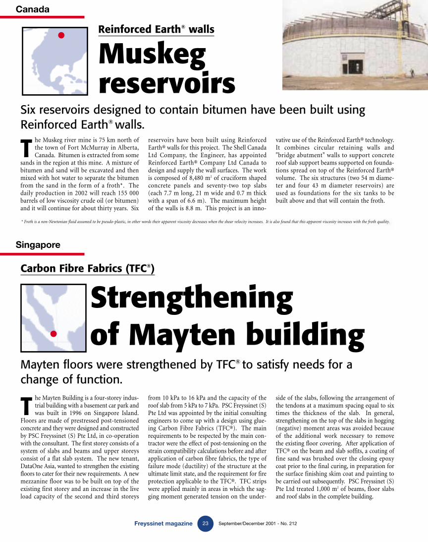
Six reservoirs designed to contain bitumen have been built usingReinforced Earth® walls.
Freyssinet magazine September/December 2001 - No. 212
Singapore
23
Canada
T he Mayten Building is a four-storey indus-trial building with a basement car park andwas built in 1996 on Singapore Island.
Floors are made of prestressed post-tensionedconcrete and they were designed and constructedby PSC Freyssinet (S) Pte Ltd, in co-operationwith the consultant. The first storey consists of asystem of slabs and beams and upper storeysconsist of a flat slab system. The new tenant,DataOne Asia, wanted to strengthen the existingfloors to cater for their new requirements. A newmezzanine floor was to be built on top of theexisting first storey and an increase in the liveload capacity of the second and third storeys
from 10 kPa to 16 kPa and the capacity of theroof slab from 5 kPa to 7 kPa. PSC Freyssinet (S)Pte Ltd was appointed by the initial consultingengineers to come up with a design using glue-ing Carbon Fibre Fabrics (TFC®). The mainrequirements to be respected by the main con-tractor were the effect of post-tensioning on thestrain compatibility calculations before and afterapplication of carbon fibre fabrics, the type offailure mode (ductility) of the structure at theultimate limit state, and the requirement for fireprotection applicable to the TFC®. TFC stripswere applied mainly in areas in which the sag-ging moment generated tension on the under-
T he Muskeg river mine is 75 km north ofthe town of Fort McMurray in Alberta,Canada. Bitumen is extracted from some
sands in the region at this mine. A mixture ofbitumen and sand will be excavated and thenmixed with hot water to separate the bitumenfrom the sand in the form of a froth*. Thedaily production in 2002 will reach 155 000barrels of low viscosity crude oil (or bitumen)and it will continue for about thirty years. Six
reservoirs have been built using ReinforcedEarth® walls for this project. The Shell CanadaLtd Company, the Engineer, has appointedReinforced Earth® Company Ltd Canada todesign and supply the wall surfaces. The workis composed of 8,480 m2 of cruciform shapedconcrete panels and seventy-two top slabs(each 7.7 m long, 21 m wide and 0.7 m thickwith a span of 6.6 m). The maximum heightof the walls is 8.8 m. This project is an inno-
vative use of the Reinforced Earth® technology.It combines circular retaining walls and"bridge abutment" walls to support concreteroof slab support beams supported on founda-tions spread on top of the Reinforced Earth®volume. The six structures (two 54 m diame-ter and four 43 m diameter reservoirs) areused as foundations for the six tanks to bebuilt above and that will contain the froth.
side of the slabs, following the arrangement ofthe tendons at a maximum spacing equal to sixtimes the thickness of the slab. In general,strengthening on the top of the slabs in hogging(negative) moment areas was avoided because of the additional work necessary to remove the existing floor covering. After application ofTFC® on the beam and slab soffits, a coating offine sand was brushed over the closing epoxycoat prior to the final curing, in preparation forthe surface finishing skim coat and painting tobe carried out subsequently. PSC Freyssinet (S)Pte Ltd treated 1,000 m2 of beams, floor slabsand roof slabs in the complete building.
Strengthening of Mayten building
Muskegreservoirs
Carbon Fibre Fabrics (TFC®)
Reinforced Earth® walls
* Froth is a non-Newtonian fluid assumed to be pseudo-plastic, in other words their apparent viscosity decreases when the shear velocity increases. It is also found that this apparent viscosity increases with the froth quality.
GB 212 magazine new OK 4/12/01 9:03 Page 23

reyssinet
In partnership with Etandex,Freyssinet is renovating theOraison canal (France). Built in the late 50's this work is included in the river Durancedevelopment scheme. The worksinclude surface treatment andwatertightness repair along part of the canal. A site to bediscovered in the next issue of Freyssinet magazine.
GB 212 couverture et 4e OK 4/12/01 9:15 Page 2