The Central Sydney Paving Design Policy - City of · PDF file2.4 Standard design details 4 ......
67
The Central Sydney Paving Design Policy
Transcript of The Central Sydney Paving Design Policy - City of · PDF file2.4 Standard design details 4 ......
The Central SydneyPaving Design Policy

Table of Contents
Page No1 Introduction 11.1 Purpose 11.2 Area to which the policy applies 12 Design Guidelines 22.1 Principles 22.2 Materials 22.3 Paving types 22.4 Standard design details 42.5 Footpath corners and junctions 52.6 Kerbs and gutters 52.7 Footpath extensions 62.8 Lanes 6
Paving Notespn1 Paving Type 2 - Flagstone Paving
pn1.1 Standard detail 8pn1.2 Standard kerb ramp 10pn1.3 Vehicular cross over 12pn1.4 Corner junction 14pn1.5 Street trees 16pn1.6 Street furniture 17pn1.7 Telephone cabinets 18pn1.8 Pit covers 19
pn2 Paving Type 3 - Asphalt Pavingwith Flagstone Marginspn2.1 Standard detail 20pn2.2 Entrance identification 22pn2.3 Standard kerb ramp 24pn2.4 Vehicular cross over 26pn2.5 Vehicular cross over - recessed vehicle entry 28pn2.6 Corner junction - preferred paving option 30pn2.7 Corner junction - second paving option 32pn2.8 Street trees 34pn2.9 Street furniture 35pn2.10 Telephone cabinets 36pn2.11 Pit covers 37
pn3 Paving Type 4 - Asphalt Pavingpn3.1 Standard detail 38pn3.2 Standard kerb ramp 40pn3.3 Vehicular cross over 42pn3.4 Vehicular cross over - recessed vehicle entry 44pn3.5 Corner junction 46pn3.6 Street trees 47pn3.7 Street furniture 48pn3.8 Telephone cabinets 49pn3.9 Pit covers 50

Table of Contents
Page Nopn4 Paving Type Junctions
pn4.1 Type 2 / type 3 - corner junction 52pn4.2 Type 3 / type 4 - corner junction 54pn4.3 Street footpath / lane footpath 56
pn5 Kerbs and Gutterspn5.1 Kerbs and gutters - Austral Verde kerb 59
pn6 Footpath Extensionspn6.1 Narrow extension 62pn6.2 Mid block extensions 63pn6.3 Wide extension 64
This policy was adopted by the City of Sydney on 26 August 1996Reprinted September 1997
© City of Sydney. All rights reserved. No part of this work will bereproduced, translated, modified, transmitted or stored in any form orby any means without the prior permission of the City of Sydney.
Enquiries regarding this document should be made in the first instance to:The One Stop Shop GPO Box 1591Town Hall House Sydney NSW 2000456 Kent Street Tel: 02 9265 9255Sydney Fax: 02 9265 9415
E-mail: [email protected]: www.cityofsydney.nsw.gov.au

1
Introduction
Purpose
Footpaths are a significant part of the public realm and their quality has adirect effect on the pedestrian experience of the city. This is acknowledgedin the principles and provisions of the City Plan, which requires footpathpaving to be provided in accordance with an overall scheme thatincorporates four paving types to be used in Central Sydney.
The purpose of this document is to provide simple urban design guidelinesto assist the Council and developers in realising the intention of the City Planand constructing a pedestrian environment of an appropriate quality andcharacter in Central Sydney.
Area to which the policy applies
This Paving Design Policy applies to all development in the area covered bythe Central Sydney Development Control Plan 1996, including the Council'sfootpath construction and maintenance work.
City West is covered by the Ultimo Pyrmont Public Domain TechnicalManual.
1
1.1
1.2

2
Design Guidelines
Principles
Footpaths should be a unifying element in the streetscape where buildings,signs, objects, people, and movement provide constant variation and change.They are to give a clear expression of pedestrian priority, and this messagemust be obvious to pedestrians and drivers. Continuity of footpathdimensions, levels, materials, and edges is therefore important. Permanentand semi-permanent objects such as kerb ramps, footpath crossings, andstreet furniture are to appear as occasional interruptions in the overallpattern rather than dominant elements of the streetscape.
All footpaths must provide ease of movement for everyone, includingpeople with different degrees of disability. Visual simplicity and observationof pedestrian desire lines is important as is the use of contrasting pavementtextures and markings to alert street users to potential hazards such asintersections and footpath crossings.
Materials
Asphalt and stone have traditionally been used for paving and kerbing inCentral Sydney. They are historically appropriate materials that complementeach other and provide a neutral setting for the architecture of the city. Theywill therefore continue to be used as principal footpath materials in CentralSydney.
Paving types
Four footpath paving types are nominated to be used in Central Sydney, allto be laid on a reinforced concrete base. They constitute a consistentsystem that provides a visually uncomplicated background to street life andfacilitates access and orientation within the city.
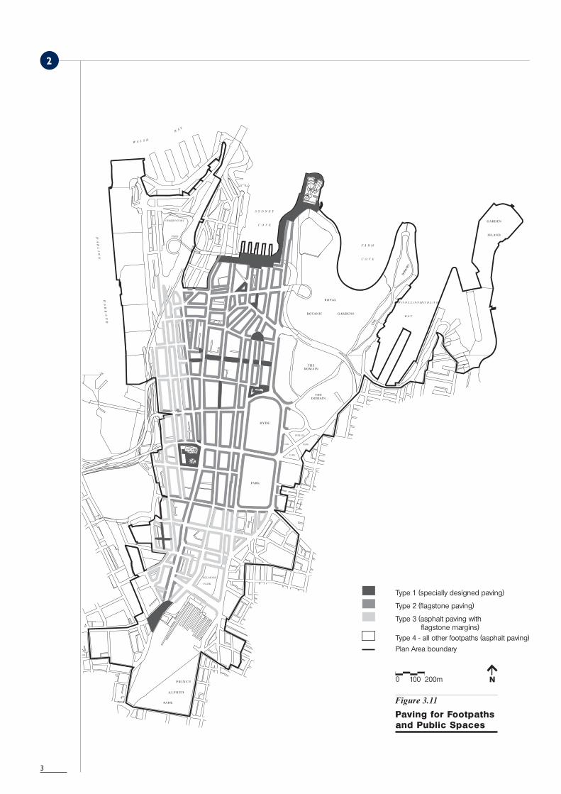
Type 1
Paving type 1 indicates special designs by Council. It is reserved for publicplaces of special significance that stand out as points of identification withinthe city fabric. Paving type 1 is to be designed individually to celebrate itsspecific civic image and role, but it must comply with the general principlesand guidelines of this document.
Types 2, 3 and 4
Paving type 2 is flagstone paving, to be used on Central Sydney's main streetsand major pedestrian routes. Paving type 3 is asphalt paving with flagstonemargins, to be used on the secondary streets that surround the main streetsand major routes. Paving type 4 is asphalt paving, to be used on theresidential and peripheral streets around the city centre.
Paving types 2, 3, and 4 provide a gradual transition from flagstone to asphalt.Types 2 and 3 both have stone margins, type 2 with stone infill and type 3with asphalt infill. The margins provide unambiguous edge definition andallow type 3 to be eventually upgraded to type 2 where desired.
2
2.1
2.2
2.3
2
3
4
2
Standard design details
The civic notes included in this document show the standard design detailsfor paving types 2, 3, and 4.
Kerb ramps
For visual consistency, kerb ramps should appear as subtle depressions in thepavement. They are to be paved with the same material as the surroundingfootpath, in accordance with the standard detail for each paving type. Theirsides are to be marked with stone inserts (type 2) or aluminium inserts(types 3 and 4) and their top edge with aluminium tactile tiles to alertpeople to the change in grade. For proper continuity and edge definition,kerbs and stone margins are to continue uninterrupted along the length ofthe street and be set down at the kerb ramps to match their profile.
At footpath corners and street intersections, kerb ramps should be locatedwithin the corner area of the footpath, aligned with the street wall, and setat a straight angle to the street alignment. This arrangement corresponds topedestrian desire lines, provides a stable crossing for people usingwheelchairs, and directs people in a straight line to a safe crossing to theopposite footpath. Kerb ramps must not be provided diagonally at thefootpath corners as this provides no protection for pedestrians from thewheels of turning vehicles and misdirects people with sight impairments intothe intersection, in the path of vehicles.
At any irregular intersections, and when a large corner radius is required, thelocation and alignment of the pedestrian crossings and kerb ramps is to bedesigned simultaneously for the whole intersection to avoid inconvenientand dangerous mismatch of facing kerb ramps.
Vehicle cross overs
Vehicle cross overs are required to provide vehicular access to carparks andservice bays across the footpath. Where installed, they are to beconstructed at footpath level and paved with the same material as thesurrounding footpath, to match the standard detail for each paving type.Their sides are to be marked with stone inserts (type 2) or aluminiuminserts (types 3 and 4) to alert people to the change in grade. For propercontinuity and edge definition, kerbs and stone margins are to continueuninterrupted along the length of the street and be set down at thevehicular crossings to match their profile.
Vehicle cross overs may only be separated by kerbs in exceptionalcircumstances outside the city centre, for industrial purposes. Recesseddouble vehicular crossings have an adverse impact on pedestrian amenityand should not be constructed along the major pedestrian thoroughfaresnominated for paving type 2.
2.4

5
2
Streetscape objects
Footpath paving is to be an uninterrupted whole that visually integrates allpermanent and semi-permanent elements of the streetscape. To maintainthe continuity of the footpath, individual objects such as street furnitureitems should generally be inserted into the paving pattern as seamlessly aspossible rather than being individually acknowledged by variations in thepavement.
Street trees, however, have a sufficient civic presence to be recognised in thepaving pattern and, in paving types 2 and 3, this is achieved by bending thekerbside stone margin around the tree grate.
Footpath corners and junctions
Junctions of different paving types indicate transition points and boundariesbetween areas of different character within the city centre. Paving types 2and 4 provide a visually simple corner definition consisting of a singlematerial, and are to be used to pave the junctions. Paving type 3 remainsbetween these two types and integrates their materials and layout patterns.
Kerbs and gutters
Stone is the traditional kerb material in Central Sydney. Existing kerbs arepredominantly trachyte and there are also small sections of the followingtypes:
> sandstone kerbs in older residential areas> concrete kerbs in peripheral areas> steel flange and concrete kerbs in Millers Point> bluestone kerbs for repairs
Concrete is the most common gutter material in Central Sydney but thereare some old sandstone gutters remaining.
Current requirements
Existing footpath kerbing
Stone kerbing is to be used for all footpath construction and maintenanceworks except for the steel flange and concrete kerbs in Millers Point that areto be retained for their heritage value. Other concrete kerbs are to bereplaced by stone. Trachyte is to be used unless the existing kerbing ispredominantly sandstone. Existing stone kerbs are to be retained andrepaired and if required reset to be 150 mm above gutter level. Forfootpath extensions existing stone kerbs are to be reset at the newalignment.
2.5
2.6

6
2
Substitute kerbs
For extensive new kerb construction, or if sandstone and trachyte becomeunavailable, Austral Verde granite with a grit blasted finish to the top and asawn finish to the face is to be used. Refer to the diagram Austral Verde KerbTypical Section.
Kerbing to traffic islands
Bluestone is to be used for kerbs around traffic islands and traffic controlelements that are physically separate from the main kerbline, subject to theCouncil’s approval.
Footpath extensions
Footpath extensions increase pedestrian presence on the streets and havea significant effect on its user pattern and civic image. They are to beconstructed according to an overall plan that takes into account the relevanturban design, heritage, and traffic issues. All footpath extensions must havea precise, geometric form and a sufficient length to contribute to the linearquality of the streetscape and the visual continuity of the pedestrian realm.
As the first priority, existing footpaths are to be retained and extensionsconstructed on the surface of the carriageway, at its grade. The original kerbis to be relocated at the new alignment. The original kerbline will becomethe new low point and the original kerb substituted by a grate. New pitsare to be installed where necessary. This implementation principle allowsincremental improvement of footpaths, ie. first stage paving followed bysecond stage extension, without loss of completed work. It retains thememory of the original kerb alignment, which contributes to the temporallayering of the streetscape and adds richness to people's experience of theurban environment.
Narrow footpath extensions may be constructed by continuing the footpathat its existing grade into the carriageway, provided that a minimum kerbheight of 100 mm can be achieved at the new alignment.
Lanes
Appropriate paving, kerbing, and detailed design of lanes and small streetswith narrow footpaths depends on the heritage status and functional role ofeach such lane and street. These will be defined and appropriate individualplans of management with specific recommendations prepared for all lanesin Central Sydney, beginning in 1996. The Council's Interim LanewayGuidelines, October 1995 are to be applied until such time that the plans ofmanagement are complete.
2.7
2.8

7 This page is blank.

Paving Type 2 - Flagstone Paving
Standard detail
8
pn1.1
pn1

9
Paving Type 2 - Flagstone Paving
Standard detail
Material
Use bluestone pavers or Austral Black or Black Grandee granite pavers orsimilar to the Council's satisfaction.
Finish
Sawn finish to bluestone.Exfoliated finish to granite.
Size
Use three sizes of stone flags in the following ratio:> type A 900 mm x 450 mm 50% of total area> type B 600 mm x 450 mm 25% of total area> type C 300 mm x 450 mm 25% of total area
Type C is the minimum size of stone to be used. Any filler stones of nonstandard sizes must be cut from type B or type C stones.
Pattern
Flagstone margins: a row of flagstones in a random order of sizes against thekerb and against the site boundary.
Flagstone infill: stretcher bond pattern with random jointing between themargins and at a right angle to them.
Installation
Install the flagstones to the Council's specifications on a reinforced concreteslab and mortar bedding with 5 mm joints between the stones and 10 - 12mm separation joints against the kerb and the site boundary. Rake joints toa 4 mm depth.
Flagstone margins: where stone margins already exist, commence theflagstone layout work from the ends of the existing ones. Elsewherecommence from either end of the area to be paved. The flagstone marginsmust be absolutely straight. Any variation of kerb width or unevenness ofbuilding wall must be accommodated by the separation joints.
Flagstone infill: commence the flagstone infill work from the kerbside margin.The edges of the completed stone paving against the margins must be cutneatly and absolutely straight.
Maintenance
Clean as necessary. Re-exfoliate on site when required to maintain slipresistance. Replace broken flagstones. Reinstate paving after works thatrequire footpath surface to be opened. Use matching stone forreplacements.
pn1.1
pn1

Paving Type 2 - Flagstone Paving
Standard kerb ramp
10
pn1.2
pn1

Paving Type 2 - Flagstone Paving
Standard kerb ramp
Paving
Material, colour, flagstone sizes, finish, pattern, and general installation as perType 2 standard detail to match the footpath.
Base
Reinforced concrete slab in the shape of the kerb ramp.
Width
The width is a multiple of 450 mm to match the size of the flagstones. Thekerb ramp should be as wide as practicable. Generally the width is to be3150 mm (900 + 1350 + 900) or 4050 mm (900 + 2250 + 900) or 6300mm (900 + 4500 + 900) as appropriate to site circumstances. At laneintersections, a minimum width of 1000 mm may be acceptable.
Alignment
Align flagstone infill joints with the sides of the kerb ramp.
Edges
Continue the kerbside flagstone margin straight across the kerb ramp. Cutstones as required to create the folds. The minimum size of stone to be usedis 300 mm x 450 mm, or its equivalent in area.
Markers
Mark the sides of the kerb ramp with round 90 mm diameter granite settsin a light grey colour and with a minimum of 30% colour contrast to thesurrounding pavement. Set the markers flush with the pavement, alignedwith the top edges of the sloping triangular sides.
Tactile paving
Mark the top of the kerb ramp with tactile aluminium tiles to the Council'ssatisfaction.
Kerb
Where kerbs already exist, reset existing kerb to lower level. Elsewhere setnew kerb to lower level.
11
pn1.2
pn1

Paving Type 2 - Flagstone Paving
Vehicular cross over
12
pn1.3
pn1
pn1
Paving Type 2 - Flagstone Paving
Vehicular cross over
Paving
Material, colour, finish, and general installation as per Type 2 standard detailto match the footpath. Use only two sizes of stone flags across the entirewidth of the footpath in the following ratio:
> type B 600 mm x 450 mm min. 60% of total area > type C 300 mm x 450 mm max 40% of total area
The minimum size of stone to be used is 300 mm x 450 mm, or itsequivalent in area.
Width
The overall width is to be divisible by 450 mm.
Base
Reinforced concrete slab in the shape of the footpath crossing.
Alignment
Align flagstone infill joints with the sides of the footpath crossing.
Edges
Continue flagstone margin straight across the footpath crossing. Cut stonesas required to create the folds.
Markers
Mark the sides of the footpath crossing with round 90 mm diameter granitesetts in a light grey colour and with a minimum of 30% colour contrast tothe surrounding pavement. Set the markers flush with the pavement, alignedwith the top edges of the sloping triangular sides.
Kerb
Where kerbs already exist, reset existing kerb to lower level. Elsewhere setnew kerb to lower level.
Threshold
The straight centre section of the footpath crossing must be narrower thanthe vehicular entry to the building. A raised threshold, preferably in flagstonepaving to match the footpath, is recommended at the vehicular entry to thebuilding.
13
pn1.3

pn1
Paving Type 2 - Flagstone Paving
Corner junction
Right angle corner
Angled corner
14
pn1.4

pn1
Paving Type 2 - Flagstone Paving
Corner junction
Setout
As a first preference, locate the kerb ramps within the intersection, align withthe site boundary, minimise the corner radius, and provide a straight kerbsection for the centre part of the ramp.
If a large radius is required, move the kerb ramps away from the intersectionand preferably align with the site boundaries. Do not orientate the kerbramp towards the centre of the intersection.
Paving layout
Flagstone margins: bring the flagstone margins around the corner at the siteboundary and the kerb. Cut stones to radius at the kerb. At the siteboundary, install a square corner stone for right angle corners, mitre thecorner stones for oblique corners, and cut stones to radius for curvedcorners.
Flagstone infill: provide an interlocking 1:1 herringbone joint to create aminimum boundary effect between the different layout directions.
Paving inserts
It may be appropriate to acknowledge and identify specific streetintersections with commemorative plaques, artworks, and similar pavinginserts in contrasting designs, materials, and colours. All paving inserts mustbe installed flush with the surrounding paving.
Kerbs
Cut to radius.The exact detailing of the corner junctions will depend on the shape andgradient of the corner.
15
pn1.4
Curved corner

pn1
Paving Type 2 - Flagstone Paving
Street trees
Tree grate
Council's standard type in cast iron, available in two sizes. Use the largegrate 1350 mm x 1350 mm on footpaths with a width of 3200 mm or more,and in public squares and plazas. Use the small grate 900 mm x 1350 mmon footpaths less than 3200 mm wide.
Installation
Install the grate frame when the pit is dug, before planting the tree. Installthe grate after planting. Install both immediately adjacent to the kerb, at aright angle to it, and align with flagstone infill joints. Set the grate flush withthe surrounding pavement and bring the stone margin around the grate.Cut stones as required. The minimum size of stone to be used is 300 mmx 450 mm.
Backfill to the top of the grate with gravel mulch for additional support.
16
pn1.5

pn1
Paving Type 2 - Flagstone Paving
Street furniture
Items
Utility poles, posts, benches, rubbish bins, drinking fountains, etc.
Installation
Install all poles and utility items such as letterboxes, signal boxes, etc. directlybehind the kerb. Bulky items must not project more than 1000 mm into thefootpath.
Install other street furniture items with their centre lines aligned and parallelto the kerb, with the kerbside edge of the bench at a distance of 450 mmfrom the inner edge of the kerb, ie. at the edge of the flagstone margin.Street furniture should preferably be installed according to a detailed layoutplan.
Construct all foundations at a depth of 80 mm from the surface of thecompleted paving to allow for its installation. Install the paving as per Type 2standard detail. Align flagstone margin joints with the poles and posts, andcut holes for them with as close a fit as possible. The minimum size of stoneto be used is 300 mm x 450 mm, or its equivalent in area.
17
pn1.6

pn1
Paving Type 2 - Flagstone Paving
Telephone cabinets
Type
Telecom/Telstra 'Heritage' cabinet.
Installation
Install single cabinet with its back to the kerb and a double cabinet with itsside to the kerb.
For a single cabinet, install concrete base block 200 mm from the kerb(standard technical requirement), aligned with the kerb, at a depth of 80 mmfrom the surface of the completed paving. For a double cabinet, installconcrete base block 300 - 400 mm from the kerb to keep the flagstonemargin intact.
Install, or reinstate, the flagstones as per Type 2 standard detail. Alignflagstone joints with the cabinet legs. Cut circular holes for the legs with asclose a fit as possible. The minimum size of stone to be used is 300 mm x450 mm, or its equivalent in area.
18
pn1.7

pn1
Paving Type 2 - Flagstone Paving
Pit covers
Type
All types.
Installation
Paving around existing pit covers: install the paving as per Type 2 standarddetail. Cut stones around the pit cover as required following the shape ofthe cover, with as close a fit as possible. The minimum size of stone to beused is 300 mm x 450 mm, or its equivalent in area. Refer to examples A,B, and D in the plan below. If a pit cover has only a slight difference inalignment to the flagstone joints, a narrow concrete edge less than 100 mmwide in a colour to match the paving may be installed around the cover.Refer to example B in the plan below.
Installation of new pit covers: install all rectilinear new pit covers parallel tothe kerb. Align as many sides of the cover with the flagstone joints aspossible. Align small covers with flagstone joints or drill a hole through theflagstone. Cut circular holes for round covers. Fit as closely as possible. Referto examples C, D, and E in the plan below.
The location of existing pits and pit covers is to be taken into account inlocating kerb ramps, vehicular crossings, street furniture, etc., to minimise anyconflicts and costs.
Cover plates
Flagstone paving to match the surrounding pavement is recommended,especially for new pit covers. Install flush with the footpath. Continue theflagstone joints across the cover regardless of its orientation. Refer toexample A in the plan below.
19
pn1.8

pn2
Paving Type 3 - Asphalt Pavingwith Flagstone Margins
Standard detail
20
pn2.1

pn2
Paving Type 3 - Asphalt Pavingwith Flagstone Margins
Standard detail
Asphalt
Surface course AC3, d=25 mm. Subsurface course AC10, d=55 mm.
Flagstones
Use bluestone pavers or Austral Black or Black Grandee granite pavers orsimilar to the Council's satisfaction.
Finish
Sawn finish to bluestone.Exfoliated finish to granite.
Size
Use three sizes of stone flags in the following ratio:> type A 900 mm x 450 mm 50% of total area> type B 600 mm x 450 mm 25% of total area> type C 300 mm x 450 mm 25% of total area
Type C is the minimum size of stone to be used. Any filler stones of nonstandard sizes must be cut from type B or type C stones.
Pattern
A row of flagstones in a random order of sizes against the kerb and againstthe site boundary.
Installation
Install the paving on a reinforced concrete slab to the Council's standards.
Flagstone margins: install the flagstones on a mortar bedding with 5 mmjoints between the stones and 10 - 12 mm separation joints against the kerband the site boundary. Rake joints to a 4 mm depth. Where stone marginsalready exist, commence the flagstone layout work from the ends of theexisting ones. Elsewhere commence from either end of the area to bepaved. The flagstone margins must be absolutely straight. Any variation ofkerb width or unevenness of building wall must be accommodated by theseparation joints.
Asphalt infill: lay the asphalt surface course as one sheet on the asphaltsubsurface course in accordance with Council's relevant specifications andAS 2734-1984 Asphalt (Hot Mixed) Paving - Guide to Good Practice.Provide a sawcut edge between the existing and new asphalt paving at aright angles to the kerb. The sawcut lines and the edges of the asphalt infillagainst the flagstone margins must be neat and absolutely straight.
Maintenance
Clean as necessary. Re-exfoliate flagstones on site when required tomaintain slip resistance. Replace broken stones. Reinstate paving afterworks that require footpath surface to be opened. Use matching stone andasphalt for replacements. When reinstalling asphalt, replace a full squareacross the entire width of the footpath with sawcut edges to existing asphaltpaving to avoid patchiness.
21
pn2.1

pn2
Paving Type 3 - Asphalt Pavingwith Flagstone Margins
Entrance identification
Paving
Flagstone infill between flagstone margins to mark the entrance. Material,colour, flagstone sizes, finish, pattern, and general installation as per Type 2standard detail.
Width
The width of the entrance paving must be at least equal to the width of thefootpath to achieve good proportions.
Alignment
Install at a right angle to the kerbside margin. Align the centre line of thepaving with the centre line of the entrance, or relate to significantarchitectural features of the building.
Edges
Cut asphalt neatly against the flagstone paving.
22
pn2.2

This page is blank.23

pn2
Paving Type 3 - Asphalt Pavingwith Flagstone Margins
Standard kerb ramp
24
pn2.3

pn2
Paving Type 3 - Asphalt Pavingwith Flagstone Margins
Standard kerb ramp
Paving
Material, colour, flagstone sizes, finish, pattern, and general installation as perType 3 standard detail to match the footpath.
Base
Reinforced concrete slab in the shape of the kerb ramp.
Width
The width is a multiple of 450 mm to match the size of the flagstones andallow Type 3 to be upgraded to Type 2 where desired. Generally the widthis to be 3150 mm (900 + 1350 + 900) or 4050 mm (900 + 2250 + 900)or 6300 mm (900 + 4500 + 900) as appropriate to site circumstances. Atlane intersections, a minimum width of 1000 mm may be acceptable.
Alignment
Install at a right angle to the kerb.
Edges
Continue the kerbside flagstone margin straight across the kerb ramp. Cutstones as required to create the folds. The minimum size of stone to be usedis 300 mm x 450 mm, or its equivalent in area.
Markers
Mark the sides of the kerb ramp on the stone margins with round 90 mmdiameter granite setts in a light grey colour and with a minimum of 30%colour contrast to the surrounding pavement, and on the asphalt surfacewith round 90 mm diameter aluminium setts or pavement studs to theCouncil's specification. Set the markers flush with the pavement, alignedwith the top edges of the sloping triangular sides. Painted markers must notbe used.
Tactile paving
Mark the top of the kerb ramp with tactile aluminium tiles to the Council'ssatisfaction.
Kerb
Where kerbs already exist, reset existing kerb to lower level. Elsewhere setnew kerb to lower level.
25
pn2.3

pn2
Paving Type 3 - Asphalt Pavingwith Flagstone Margins
Vehicular cross over
26
pn2.4

pn2
Paving Type 3 - Asphalt Pavingwith Flagstone Margins
Vehicular cross over
Paving
Material, colour, finish, and general installation as per Type 3 standard detailto match the footpath. For the margin, use two sizes of stone flags in thefollowing ratio:
> type B 600 mm x 450 mm min 60% of total area> type C 300 mm x 450 mm max 40% of total area
The minimum size of stone to be used is 300 mm x 450 mm, or itsequivalent in area.
Width
The overall width is to be divisible by 450 mm.
Base
Reinforced concrete slab in the shape of the footpath crossing.
Alignment
Install at a right angle to the kerb.
Edges
Continue flagstone margins straight across the footpath crossing. Cut stonesas required for the sloping triangular sides.
Markers
Mark the sides of the kerb ramp on the stone margins with round 90 mmdiameter granite setts in a light grey colour and with a minimum of 30%colour contrast to the surrounding pavement, and on the asphalt surfacewith round 90mm diameter aluminium setts or pavement studs to theCouncil's specification. Set the markers flush with the pavement, alignedwith the top edges of the sloping triangular sides. Painted markers must notbe used.
Kerb
Where kerbs already exist, reset existing kerb to lower level. Elsewhere setnew kerb to lower level.
Threshold
The straight centre section of the footpath crossing must be narrower thanthe vehicular entry to the building. A raised threshold, preferably in flagstonepaving to match the margins, is recommended at the vehicular entry to thebuilding.
27
pn2.4

pn2
Paving Type 3 - Asphalt Pavingwith Flagstone Margins
Vehicular cross over - recessed vehicle entry
28
pn2.5

pn2
Paving Type 3 - Asphalt Pavingwith Flagstone Margins
Vehicular cross over - recessed vehicle entry
Paving
Material, colour, finish, and general installation as per Type 3 standard detailto match the footpath. For the margin, use two sizes of stone flags in thefollowing ratio:
> type B 600 mm x 450 mm min 60% of total area> type C 300 mm x 450 mm max 40% of total area
The minimum size of stone to be used is 300 mm x 450 mm, or itsequivalent in area.
Width
The overall width is to be divisible by 450 mm.
Base
Reinforced concrete slab in the shape of the footpath crossing.
Alignment
Install at a right angle to the kerb.
Edges
Continue flagstone margins straight across the footpath crossing. Cut stonesas required for the sloping triangular sides.
Markers
Mark the sides of the kerb ramp on the stone margins with round 90 mmdiameter granite setts in a light grey colour with a minimum of 30% colourcontrast to the surrounding pavement, and on the asphalt surface withround 90mm diameter aluminium setts or pavement studs to the Council'sspecification. Set the markers flush with the pavement, aligned with the topedges of the sloping triangular sides. Painted markers must not be used.
Kerb
Where kerbs already exist, reset existing kerb to lower level. Elsewhere setnew kerb to lower level.
Threshold
The straight centre section of the footpath crossing must be narrower thanthe vehicular entry to the building. A raised threshold, preferably in flagstonepaving to match the margins, is recommended at the vehicular entry to thebuilding.
Recess
Flagstone paving to match the flagstone margin is recommended.
29
pn2.5

pn2
Paving Type 3 - Asphalt Pavingwith Flagstone Margins
Corner junction - preferred paving option
Right angle corner
Angled corner
30
pn2.6

pn2
Paving Type 3 - Asphalt Pavingwith Flagstone Margins
Corner junction - preferred paving option
Setout
As a first preference, locate the kerb ramps within the intersection, align withthe site boundary, minimise the corner radius, and provide a straight kerbsection for the centre part of the ramp.
If a large radius is required, move the kerb ramps away from the intersectionand preferably align with the site boundaries. Do not orientate the kerbramp towards the centre of the intersection.
Paving layout
Flagstone margins: bring the flagstone margins around the corner at the siteboundary and the kerb. Cut stones to radius at the kerb. At the siteboundary, install a square corner stone for right angle corners, mitre thecorner stones for oblique corners, and cut stones to radius for curvedcorners.
Asphalt infill: install asphalt infill as per Type 3 standard detail.
Paving inserts
It may be appropriate to acknowledge and identify specific streetintersections with commemorative plaques, artworks, and similar pavinginserts in contrasting designs, materials, and colours. All paving inserts mustbe installed flush with the surrounding paving.
Kerbs
Cut to radius.The exact detailing of the corner junctions will depend on the shape andgradient of the corner.
31
pn2.6
Curved corner

pn2
Paving Type 3 - Asphalt Pavingwith Flagstone Margins
Corner junction - second paving option
32
pn2.7
Right angle corner
Angled corner

pn2
Paving Type 3 - Asphalt Pavingwith Flagstone Margins
Corner junction - second paving option
Setout
As a first preference, locate the kerb ramps within the intersection, align withthe site boundary, minimise the corner radius, and provide a straight kerbsection for the centre part of the ramp.
If a large radius is required, move the kerb ramps away from the intersectionand preferably align with the site boundaries. Do not orientate the kerbramp towards the centre of the intersection.
Paving layout
Flagstone margins: bring the flagstone margins around the corner at the siteboundary and the kerb. Cut stones to radius at the kerb. At the siteboundary, install a square corner stone for right angle corners, mitre thecorner stones for oblique corners, and cut stones to radius for curvedcorners.
Flagstone infill: install flagstone infill as per Type 2 standard detail, with aninterlocking 1:1 herringbone joint to create a minimum boundary effectbetween the different layout directions. At right angle building corners,extend around the corner to align with the edges of the kerb ramps. Atoblique building corners, extend one row of flagstones over the mitre joint.At curved corners, extend one row of flagstones over the end of curve.Provide a sawcut edge to adjoining asphalt paving.
Paving inserts
It may be appropriate to acknowledge and identify specific streetintersections with commemorative plaques, artworks, and similar pavinginserts in contrasting designs, materials, and colours. All paving inserts mustbe installed flush with the surrounding paving.
Kerbs
Cut to radius.The exact detailing of the corner junctions will depend on the shape andgradient of the corner.
33
pn2.7
Curved corner
pn2
Paving Type 3 - Asphalt Pavingwith Flagstone Margins
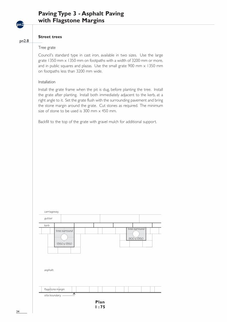
Street trees
Tree grate
Council's standard type in cast iron, available in two sizes. Use the largegrate 1350 mm x 1350 mm on footpaths with a width of 3200 mm or more,and in public squares and plazas. Use the small grate 900 mm x 1350 mmon footpaths less than 3200 mm wide.
Installation
Install the grate frame when the pit is dug, before planting the tree. Installthe grate after planting. Install both immediately adjacent to the kerb, at aright angle to it. Set the grate flush with the surrounding pavement and bringthe stone margin around the grate. Cut stones as required. The minimumsize of stone to be used is 300 mm x 450 mm.
Backfill to the top of the grate with gravel mulch for additional support.
34
pn2.8

pn2
Paving Type 3 - Asphalt Pavingwith Flagstone Margins
Street furniture
Items
Utility poles, posts, benches, rubbish bins, drinking fountains, etc.
Installation
Install all poles and utility items such as letterboxes, signal boxes, etc. directlybehind the kerb. Bulky items must not project more than 1000 mm into thefootpath. Install other street furniture items with their centre lines alignedand parallel to the kerb, with the kerbside edge of the bench at a distanceof 450 mm from the inner edge of the kerb, ie. at the edge of the flagstonemargin. Street furniture should preferably be installed according to adetailed layout plan.
Construct all foundations at a depth of 80 mm from the surface of thecompleted paving to allow for its installation. Install the paving as per Type 3standard detail. Align flagstone margin joints with the poles and posts, andcut holes for them with as close a fit as possible. The minimum size of stoneto be used is 300 mm x 450 mm, or its equivalent in area. Cut or tampasphalt neatly at the poles and furniture legs. When reinstalling asphalt,replace a full square across the entire width of the footpath with sawcutedges to existing asphalt paving to avoid patchiness.
35
pn2.9

pn2
Paving Type 3 - Asphalt Pavingwith Flagstone Margins
Telephone cabinets
Type
Telecom/Telstra 'Heritage' cabinet.
Installation
Install single cabinet with its back to the kerb and a double cabinet with itsside to the kerb.
For a single cabinet, install concrete base block 200 mm from the kerb(standard technical requirement), aligned with the kerb, at a depth of 80 mmfrom the surface of the completed paving. For a double cabinet, installconcrete base block 300 - 400 mm from the kerb to keep the flagstonemargin intact.
Install, or reinstate, the paving as per Type 3 standard detail. Cut or tampasphalt neatly at the cabinet legs. When reinstalling asphalt, replace a fullsquare across the entire width of the footpath with sawcut edges to existingasphalt paving to avoid patchiness.
36
pn2.10

pn2
Paving Type 3 - Asphalt Pavingwith Flagstone Margins
Pit covers
Type
All types.
Installation
Paving around existing pit covers: install the paving as per Type 3 standarddetail. Cut or tamp asphalt neatly to the pit cover edges with as close a fitas possible. Refer to examples B, C, D, and E in the plan below. Within theflagstone margins, cut stones around the pit cover as required following theshape of the cover, with as close a fit as possible. The minimum size of stoneto be used is 300 mm x 450 mm, or its equivalent in area. Refer to exampleA below.
Installation of new pit covers: install all rectilinear new pit covers parallel tothe kerb and into the asphalt infill area to keep the flagstone margins intact.On existing asphalt areas, cut the asphalt neatly to exactly fit the new pitcover, or reinstall a full square of asphalt across the entire width of theasphalt paving to avoid patchiness. Refer to examples E and B below.
The location of existing pits and pit covers is to be taken into account inlocating kerb ramps, vehicular crossings, street furniture, etc., to minimise anyconflicts and costs.
Cover plates
Paving to match the surrounding pavement is recommended, especially fornew pit covers. Install flush with the footpath. Continue the flagstonemargin across the cover regardless of its orientation. Refer to example A inthe plan below.
37
pn2.11
pn3
Paving Type 4 - Asphalt Paving
Standard detail
38
pn3.1

pn3
Paving Type 4 - Asphalt Paving
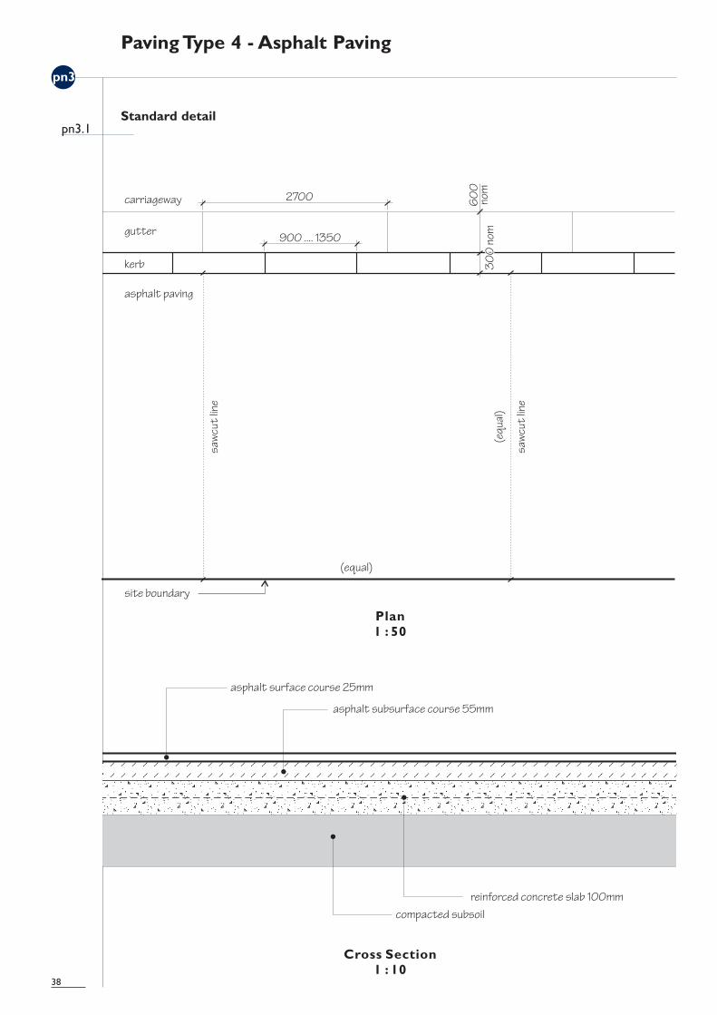
Standard detail
Material
Asphalt surface course AC3, d=25 mm.
Installation
Install the paving on a 100 mm concrete slab to the Council's standards. Laythe asphalt surface course as one sheet on the asphalt subsurface course inaccordance with Council's relevant specifications and AS 2734-1984 Asphalt(Hot Mixed) Paving - Guide to Good Practice.
Provide a sawcut edge between the existing and new asphalt paving at aright angle to the kerb.The sawcut lines must be neat and absolutely straight.
Maintenance
Clean as necessary. Reinstate paving after works that require footpathsurface to be opened. Use matching asphalt for replacements. Whenreinstalling asphalt, replace a full square across the entire width of thefootpath with sawcut edges to existing asphalt paving to avoid patchiness.
39
pn3.1

pn3
Paving Type 4 - Asphalt Paving
Standard kerb ramp
40
pn3.2

pn3
Paving Type 4 - Asphalt Paving
Standard kerb ramp
Paving
Material, colour, finish, and general installation as per Type 4 standard detailto match the footpath.
Base
Reinforced concrete slab in the shape of the crossover. Refer to crosssection.
Width
The width is a multiple of 450 mm to match the size of the flagstones andallow Type 4 to be upgraded to Type 3 where desired. Generally the widthis to be 3150 mm (900 + 1350 + 900) or 4050 mm (900 + 2250 + 900)or 6300 mm (900 + 4500 + 900) as appropriate to site circumstances. Atlane intersections, a minimum width of 1000 mm may be acceptable.
Alignment
Install at a right angle to the kerb and maintain a regular geometric form.
Markers
Mark the sides of the crossover with round 90 mm diameter aluminium settsor pavement studs to the Council's specification. Set the markers flush withthe pavement, aligned with the top edges of the sloping triangular sides.Painted markers must not be used.
Tactile paving
Mark the top of the kerb ramp with tactile aluminium tiles to the Council'ssatisfaction.
Kerb
Where kerbs already exist, reset existing kerb to lower level. Elsewhere setnew kerb to lower level.
41
pn3.2

pn3
Paving Type 4 - Asphalt Paving
Vehicular cross over
42
pn3.3

pn3
Paving Type 4 - Asphalt Paving
Vehicular cross over
Paving
Material, colour, finish, and general installation as per Type 4 standard detailto match the footpath.
Base
Reinforced concrete slab in the shape of the footpath crossing.
Alignment
Install at a right angle to the kerb and maintain a regular form.
Markers
Mark the sides of the footpath crossing with round 90 mm diameteraluminium setts or pavement studs to the Council's specification. Set themarkers flush with the pavement, aligned with the top edges of the slopingtriangular sides. Painted markers must not be used.
Kerb
Where kerbs already exist, reset existing kerb to lower level. Elsewhere setnew kerb to lower level.
Threshold
The straight centre section of the footpath crossing must be narrower thanthe vehicular entry to the building. A raised threshold, preferably withcontrasting paving, is recommended at the vehicular entry to the building.
43
pn3.3

pn3
Paving Type 4 - Asphalt Paving
Vehicular cross over - recessed vehicle entry
44
pn3.4

pn3
Paving Type 4 - Asphalt Paving
Vehicular cross over - recessed vehicle entry
Paving
Material, colour, finish, and general installation as per Type 4 standard detailto match the footpath.
Base
Reinforced concrete slab in the shape of the footpath crossing.
Alignment
Install at a right angle to the kerb and maintain a regular form.
Markers
Mark the sides of the footpath crossing with round 90 mm diameteraluminium setts or pavement studs to the Council's specification. Set themarkers flush with the pavement, aligned with the top edges of the slopingtriangular sides. Painted markers must not be used.
Kerb
Where kerbs already exist, reset existing kerb to lower level. Elsewhere setnew kerb to lower level.
Threshold
The straight centre section of the footpath crossing must be narrower thanthe vehicular entry to the building. A raised threshold is recommended atthe vehicular entry to the building.
Recess
Contrasting paving is recommended.
45
pn3.4

pn3
Paving Type 4 - Asphalt Paving
Corner junction
Setout
As a first preference, locate the kerb ramps within the intersection, align withthe site boundary, minimise the corner radius, and provide a straight kerbsection for the centre part of the ramp.
If a large radius is required, move the kerb ramps away from the intersectionand preferably align with the site boundaries. Do not orientate the kerbramp towards the centre of the intersection.
Paving layout
Asphalt installed as per Type 4 standard detail.
Paving inserts
It may be appropriate to acknowledge and identify specific streetintersections with commemorative plaques, artworks, and similar pavinginserts in contrasting designs, materials, and colours. All paving inserts mustbe installed flush with the surrounding paving.
Kerbs
Cut to radius.
The exact detailing of the corner junctions will depend on the shape andgradient of the corner.
46
pn3.5
pn3
Paving Type 4 - Asphalt Paving
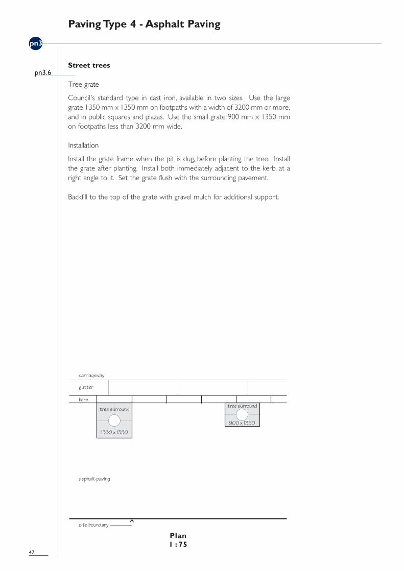
Street trees
Tree grate
Council's standard type in cast iron, available in two sizes. Use the largegrate 1350 mm x 1350 mm on footpaths with a width of 3200 mm or more,and in public squares and plazas. Use the small grate 900 mm x 1350 mmon footpaths less than 3200 mm wide.
Installation
Install the grate frame when the pit is dug, before planting the tree. Installthe grate after planting. Install both immediately adjacent to the kerb, at aright angle to it. Set the grate flush with the surrounding pavement.
Backfill to the top of the grate with gravel mulch for additional support.
47
pn3.6

pn3
Paving Type 4 - Asphalt Paving
Street furniture
Items
Utility poles, posts, benches, rubbish bins, drinking fountains, etc.
Installation
Install all poles and utility items such as letterboxes, signal boxes, etc. directlybehind the kerb. Bulky items must not project more than 1000 mm into thefootpath. Install other street furniture items with their centre lines alignedand parallel to the kerb, with the kerbside edge of the bench at a distanceof 450 mm from the inner edge of the kerb, to allow for future upgrading toType 3 paving where desired. Street furniture should preferably be installedaccording to a detailed layout plan.
Construct all foundations at a depth of 80 mm from the surface of thecompleted paving to allow for its installation. Install the paving as per Type 4standard detail. Cut or tamp asphalt neatly at the poles and furniture legs.When reinstalling asphalt, replace a full square across the entire width of thefootpath with sawcut edges to existing asphalt paving to avoid patchiness.
48
pn3.7

pn3
Paving Type 4 - Asphalt Paving
Telephone cabinets
Type
Telecom/Telstra 'Heritage' cabinet.
Installation
Install single cabinet with its back to the kerb and a double cabinet with itsside to the kerb.
For a single cabinet, install concrete base block 200 mm from the kerb(standard technical requirement), aligned with the kerb, at a depth of 80 mmfrom the surface of the completed paving. For a double cabinet, installconcrete base block 300 - 400 mm from the kerb to allow for futureupgrading to Type 3 paving where desired.
Install, or reinstate, the paving as per Type 4 standard detail. Cut or tampasphalt neatly at the cabinet legs. When reinstalling asphalt, replace a fullsquare across the entire width of the footpath with sawcut edges to existingasphalt paving to avoid patchiness.
49
pn3.8

pn3
Paving Type 4 - Asphalt Paving
Pit covers
Type
All types.
Installation
Paving around existing pit covers: Install the paving as per Type 4 standarddetail. Cut or tamp asphalt neatly to the pit cover edges with as close a fitas possible.
Installation of new pit covers: install all rectilinear new pit covers parallel tothe kerb and at a minimum distance of 450 mm from the kerb and the siteboundary to allow for future upgrading to Type 3 paving where desired. Onexisting asphalt areas, cut the asphalt neatly to exactly fit the new pit cover,or reinstall a full square of asphalt across the entire width of the asphaltpaving to avoid patchiness. Refer to examples E and B in the plan below.
The location of existing pits and pit covers is to be taken into account inlocating kerb ramps, vehicular crossings, street furniture, etc., to minimise anyconflicts and costs.
Cover plates
Paving to match the surrounding pavement is recommended, especially fornew pit covers. Install flush with the footpath.
50
pn3.9

This page is blank.51
pn4
Paving Type Junctions
Type 2 / type 3 - corner junction
52
pn4.1
Right angle corner
Angled corner
pn4
Paving Type Junctions
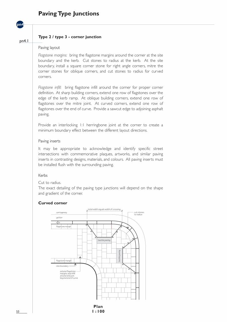
Type 2 / type 3 - corner junction
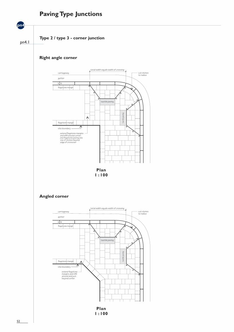
Paving layout
Flagstone margins: bring the flagstone margins around the corner at the siteboundary and the kerb. Cut stones to radius at the kerb. At the siteboundary, install a square corner stone for right angle corners, mitre thecorner stones for oblique corners, and cut stones to radius for curvedcorners.
Flagstone infill: bring flagstone infill around the corner for proper cornerdefinition. At sharp building corners, extend one row of flagstones over theedge of the kerb ramp. At oblique building corners, extend one row offlagstones over the mitre joint. At curved corners, extend one row offlagstones over the end of curve. Provide a sawcut edge to adjoining asphaltpaving.
Provide an interlocking 1:1 herringbone joint at the corner to create aminimum boundary effect between the different layout directions.
Paving inserts
It may be appropriate to acknowledge and identify specific streetintersections with commemorative plaques, artworks, and similar pavinginserts in contrasting designs, materials, and colours. All paving inserts mustbe installed flush with the surrounding paving.
Kerbs
Cut to radius.The exact detailing of the paving type junctions will depend on the shapeand gradient of the corner.
53
pn4.1
Curved corner

pn4
Paving Type Junctions
Type 3 / type 4 - corner junction
54
pn4.2
Right angle corner
Angled corner

pn4
Paving Type Junctions
Type 3 / type 4 - corner junction
Paving layout
Bring the asphalt paving around the corner for proper corner definition.
At sharp building corners, end the flagstone margin at a distance of 450 mmfrom the edge of the kerb ramp. At oblique building corners, end theflagstone margin at the building corner. At curved corners, end the flagstonemargin at the end of the curve. Provide a sawcut edge to adjoining asphaltpaving.
Paving inserts
It may be appropriate to acknowledge and identify specific streetintersections with commemorative plaques, artworks, and similar pavinginserts in contrasting designs, materials, and colours. All paving inserts mustbe installed flush with the surrounding paving.
Kerbs
Cut to radius.
The exact detailing of the paving type junctions will depend on the shapeand gradient of the corner.
55
pn4.2
Curved corner

pn4
Paving Type Junctions
Street footpath / lane footpath
56
pn4.3
Street footpath type 2 / lane footpath
Street footpath type 3 / lane footpath

pn4
Paving Type Junctions
Street footpath / lane footpath
Paving layout
The laneway footpaths will be paved in asphalt. Bring the street footpathpaving across the corner and end the laneway paving at the site boundaryto the street.
Paving type 2 street footpaths: bring the flagstone margins around the cornerat the site boundary and the kerb. Cut stones to radius at the kerb. Installthe flagstone infill as per Type 2 standard detail. Cut stones as requiredagainst the margin. The minimum size of stone to be used is 300 mm x 450mm, or its equivalent in area. Provide a sawcut edge to the laneway asphalt.
Paving type 3 street footpaths: bring the flagstone margins around the cornerat the site boundary and the kerb. Cut stones to radius at the kerb. Installthe asphalt infill as per Type 3 standard detail. Provide a sawcut edge to thelaneway asphalt.
Type 4 street footpaths: install asphalt paving as per Type 4 standard detail.Provide a sawcut edge to the laneway asphalt.
Kerbs
Cut to radius.
Kerb ramps
Install the kerb ramps as the standard kerb ramp, but with reduceddimensions to fit into the available space. For Type 3 and Type 4, set out toallow for future flagstone paving where desired.
The exact detailing of the junctions will depend on the local conditions.
57
pn4.3
Street footpath type 4 / lane footpath

This page is blank.58

pn5
Kerbs and Gutters
Typical plan and section
59
pn5.1
pn5
Kerbs and Gutters
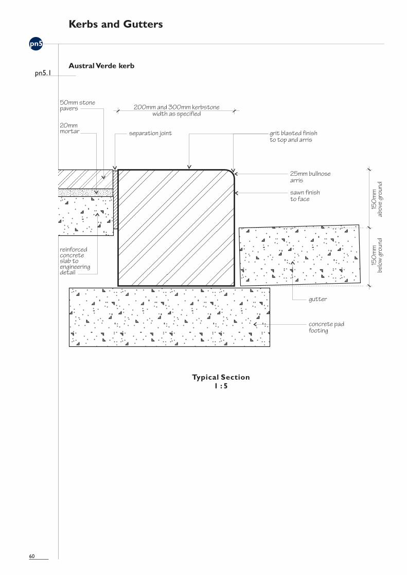
Austral Verde kerb
60
pn5.1

pn5
Kerbs and Gutters
Kerbs
Material
> trachyte kerbing generally> sandstone kerbing is the first option in heritage and residential areas
nominated for paving type 4 where there is an existing precedent ofsandstone kerbing
> bluestone kerbing is to be used for traffic islands> Austral Verde granite kerbing is to be used for extensive new sections of
kerbing e.g. footpath extensions, as a substitute for trachyte
Footpath extensions and traffic islands are to be implemented according toa specific plan to ensure sufficient consistency with surrounding areas andare subject to Council’s approval.
Any stone kerbs, especially trachyte and sandstone, made available infootway reconstruction work are to be retrieved for use in the appropriateareas.
Finish
> trachyte - sparrow pecked finish> sandstone and bluestone - sawn finish> Austral Verde granite - grit blasted finish to the top and the arris and sawn
finish to the face
Width
300 mm or 200 mm to match the predominant kerb width in the block.
Gutters
Material
Concrete or stone to match existing.
Finish
To match adjoining gutters.
Width
To match adjoining gutters.
Installation
The kerbs and gutters must be installed absolutely straight and cut to radiusat footpath corners. Reuse old stone kerbs and gutters and avoid mixingwith new ones. Match new work with the stone, size, shape, finish, andjointing of adjoining kerbs and gutters.
61
pn5.1

pn6
Footpath Extensions
Narrow extension
Width
Minimum 900 mm (nominal).
Length
A multiple of 450 mm between the kerbs is preferred; minimum nominallength 10800 mm.
Installation
Apply equal width to the entire length of the extension. Install existing kerbto new location. Complete new kerb with matching kerbstone sections.Reconstruct gutter to match adjoining gutters.
Install paving as per the relevant standard detail to match the existing orupgraded footpath.
62
pn6.1

pn6
Footpath Extensions
Mid block extensions
Width
2700 mm (nominal).
Length
A multiple of 450 mm between the kerbs is preferred; minimum nominallength 12600 mm. A nominal length of 15150 mm will accommodate onestreet tree. A nominal length of 30300 mm will accommodate two streettrees.
Installation
Install existing kerb to new location. Complete new kerb with matchingkerbstone sections. Reconstruct gutter to match adjoining gutters.Construct new internal gutter at the old kerbline. Cover with selected metalgrate to the Council's satisfaction.
Install pit at the end of grate where required. Install paving as per therelevant standard detail to match the existing or upgraded footpath.
63
pn6.2

pn6
Footpath Extensions
Wide extension
Width
2700 mm (nominal).
Length
A multiple of 450 mm between the kerbs is preferred; minimum nominallength 12150 mm. This will accommodate one street tree where desired.
Installation
Install existing kerb to new location. Complete new kerb with matchingkerbstone sections. Reconstruct gutter to match adjoining gutters.Construct new internal gutter at the old kerbline. Cover with selected metalgrate to the Council's satisfaction.
Install pit at the end of grate where required. Install paving as per therelevant standard detail to match the existing or upgraded footpath.
64
pn6.3