TGAS - Cambridge · 4/11/2018 · SHIRU CAFE One Brattle STreet, Cambridge. MA 02138 TGAS 1720 -...
17
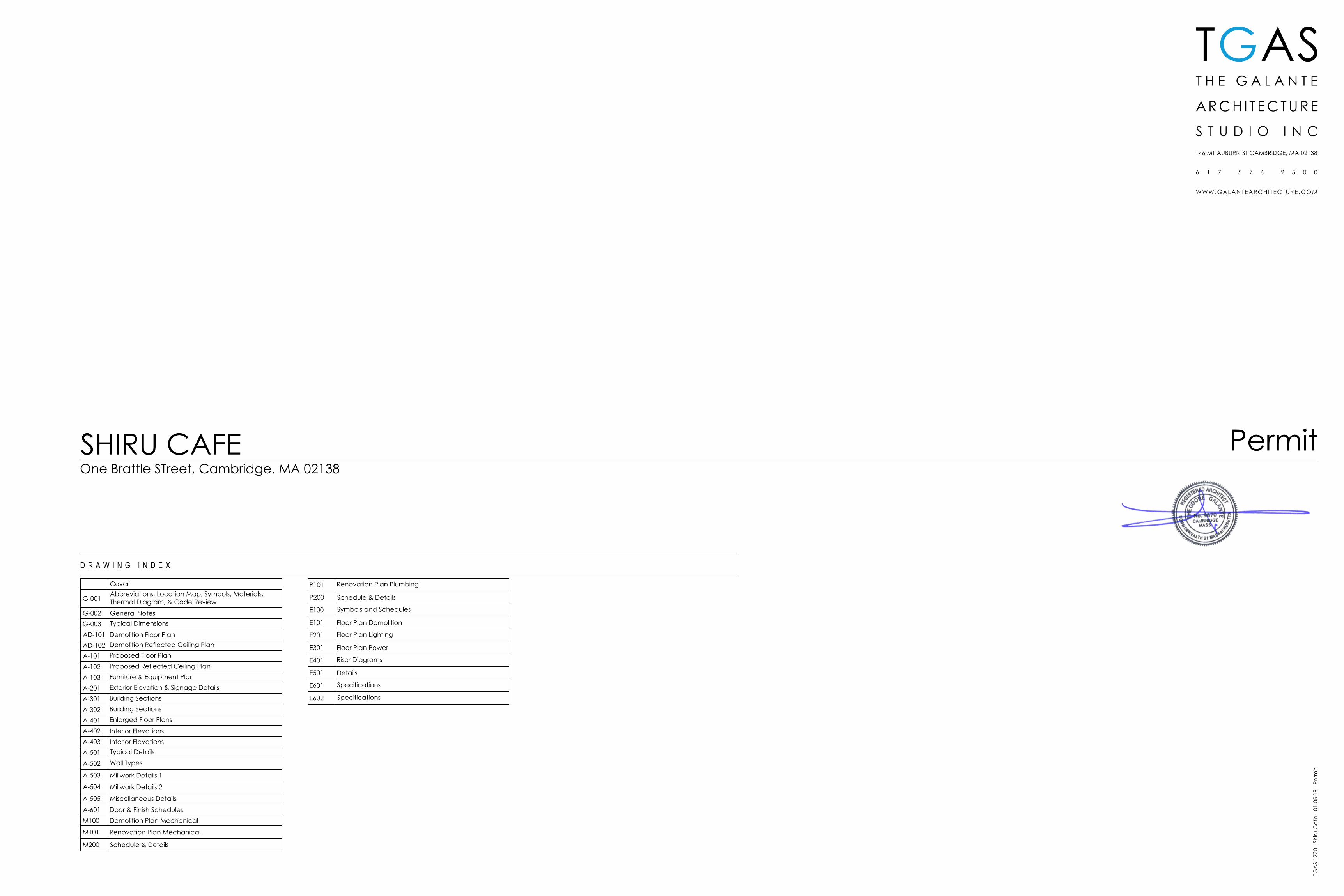
SHIRU CAFE One Brattle STreet, Cambridge. MA 02138 TGAS 1720 - Shiru Cafe - 01.05.18 - Permit T G AS Cover G-001 Abbreviations, Location Map, Symbols, Materials, Thermal Diagram, & Code Review G-002 General Notes G-003 Typical Dimensions AD-101 Demolition Floor Plan AD-102 Demolition Reflected Ceiling Plan A-101 Proposed Floor Plan A-102 Proposed Reflected Ceiling Plan A-103 Furniture & Equipment Plan A-201 Exterior Elevation & Signage Details A-301 Building Sections A-302 Building Sections A-401 Enlarged Floor Plans A-402 Interior Elevations A-403 Interior Elevations A-501 Typical Details A-502 Wall Types A-503 Millwork Details 1 A-504 Millwork Details 2 A-505 Miscellaneous Details A-601 Door & Finish Schedules M100 Demolition Plan Mechanical M101 Renovation Plan Mechanical M200 Schedule & Details P101 Renovation Plan Plumbing P200 Schedule & Details E100 Symbols and Schedules E101 Floor Plan Demolition E201 Floor Plan Lighting E301 Floor Plan Power E401 Riser Diagrams E501 Details E601 Specifications E602 Specifications Permit
Transcript of TGAS - Cambridge · 4/11/2018 · SHIRU CAFE One Brattle STreet, Cambridge. MA 02138 TGAS 1720 -...
SHIRU CAFEOne Brattle STreet, Cambridge. MA 02138
TGA
S 17
20 -
Shiru
Caf
e - 0
1.05
.18
- Per
mit
TGAS
Cover
G-001Abbreviations, Location Map, Symbols, Materials,Thermal Diagram, & Code Review
G-002 General NotesG-003 Typical Dimensions
AD-101 Demolition Floor PlanAD-102 Demolition Reflected Ceiling Plan
A-101 Proposed Floor Plan
A-102 Proposed Reflected Ceiling Plan
A-103 Furniture & Equipment Plan
A-201 Exterior Elevation & Signage Details
A-301 Building Sections
A-302 Building Sections
A-401 Enlarged Floor Plans
A-402 Interior ElevationsA-403 Interior ElevationsA-501 Typical Details
A-502 Wall Types
A-503 Millwork Details 1
A-504 Millwork Details 2
A-505 Miscellaneous Details
A-601 Door & Finish SchedulesM100 Demolition Plan Mechanical
M101 Renovation Plan Mechanical
M200 Schedule & Details
P101 Renovation Plan Plumbing
P200 Schedule & Details
E100 Symbols and Schedules
E101 Floor Plan Demolition
E201 Floor Plan Lighting
E301 Floor Plan Power
E401 Riser Diagrams
E501 Details
E601 Specifications
E602 Specifications
Permit
M
O
U
N
T
A
U
B
U
R
N
S
T
R
E
E
T
M
I
F
F
L
I
N
P
L
A
C
E
B
R
A
T
T
L
E
S
T
R
E
E
T
B
R
A
T
T
L
E
S
T
R
E
E
T
B
R
A
T
T
L
E
S
Q
U
A
R
E
M
O
U
N
T
A
U
B
U
R
N
S
T
R
E
E
T
As Noted
TGAS
G-001
Abbreviations,Location Map,Symbols, &Materials
ACCBL Accessible
ACT Acoustical Ceiling Tile
AD Area Drain
ADJ Adjustable
ADJCT Adjacent
AFF Above Finish Floor
AGGR Aggregate
ALUM Aluminum
& And
ANOD Anodized
APPROX
Approximately
ARCH Architectural
@ At
BD Board
BITM Bituminous
BLK Black/Block
BLKG Blocking
BM Beam
B.O. Bottom Of
BOT Bottom
BSMT Basement
BYND Beyond
CAB Cabinet
CB Catch Basin
CEM Cement
CER Ceramic
CHNL Channel
C.I. Cast Iron
CIP Cast In Place
C.J. Control Joint
CKG Caulking
CL Closet
CLG Ceiling
CLR Clear
CMU Concrete Masonry Unit
CNTR Counter
C.O. Concrete Opening
C/O Clean Out
COL Column
COMPR Compressible
CONC Concrete
Construction
CONT Continuous
CORR Corridor
CPT Carpet
C.T. Ceramic Tile
CTR Center
℄ Centerline
CTSK Countersunk
CTYD Courtyard
CUH Cabinet Unit Heater
CXN Connection
DBL Double
DEMO Demolish or Demolition
DEPT Department
DET Detail
DF Drinking Fountain
DF HP Handicapped Drinking Fountain
DIA Diameter
Ø Diameter
DIM Dimension
DIR Direction(s)
DISP Dispenser
DN Down
DR Door
DS Downspout
DWG Drawing
DWR Drawer
DWV Drain-Waste-Vent Pipe
E Electrical
EA Each
EBU Emergency Backup
EJ Expansion Joint
EL Elevation
ELASTO Elastomeric
ELEC Electrical
ELEV Elevator or Elevation
EMER Emergency
ENCL Enclosure
E.P. Electric Panelboard
EPDM Ethylene Propylene DieneM-Class
EQ Equal
EQPT Equipment
ETR Existing To Remain
EWC Electric Water Cooler
EXP Expansion
EXTG Existing
EXP JT Expansion Joint
EXT Exterior
FA Fire Alarm
FD Floor Drain or Fire Department
FDC Fire Department Connection
FDN Foundation
FE Fire Extinguisher
FEC Fire Extinguisher Cabinet
FF Finish Floor
FGL Fiberglass
FIN Finish
FIXT Fixture
FLR Floor
FLUOR Fluorescent
F/O Face Of
FP Fire Protection
FRT Fire Retardant Treated
FT Foot or Feet
FURR Furring
FUT Future
GA Gauge
GALV Galvanized
GC General Contractor
GEN General/Generator
GFCIGround Fault Circuit Interrupter(Outlet)
GFIGround Fault Circuit Interrupter(Outlet)
GKT Gasket
GL Glass
GND Ground
GR Grade
GWB Gypsum Wallboard
GYP Gypsum
H High
HB Hose Bib
HC Hollow Core
HD Heavy Duty
HDR Header
HDWD Hardwood
HDWR Hardware
HGR Hanger
HM Hollow Metal
HOR Horizontal
HORIZ Horizontal
HR Hour
HSS Hollow Structural Steel
HT Height
HVACHeating, Ventilating, and AirConditioning
HVY Heavy
HW Hot Water
I/C Insulated Ceiling
ICF Insulated Concrete Form
ID Inside Diameter
ILO In Lieu Of
IN Inch
INCL Incline/Include
INSUL Insulation
INT Interior
IP Iron Pipe
IRGWB Impact Resistant GypsumWallboard
JAN Janitor
JBOX Junction Box
JC Janitor's Closet
JCT Junction
JST Joist
JT Joint
KIT Kitchen
KO Knockout
KPL Kickplate
KWH Kilowatt Hour
L Length/long
LAD Ladder
LAM Laminated
LAT Lateral
LAV Lavatory
LCC Lead Coated Copper
LH Left Hand
LHR Left Hand Reverse
LKR Locker
LT Light
M Mechanical
MAINT Maintenance
MATL Material
MAX Maximum
MECH Mechanical
MED Medium
MEMB Membrane
MET Metal
MFR Manufacturer
MH Manhole
MIN Minimum
MISC Miscellaneous
MO Masonry Opening
MOD Modified
MT Men's Toilet
MTD Mounted
MTL Metal
MUL Mullion
MWK Millwork
NATL Natural
NFA Net Free Area
NIC Not In Contract
NMT Non-Mettalic
NO Number
NOM Nominal
NR Noise Reduction
NRC Noise Reduction Coefficient
NTS Not To Scale
OC On Center
OD Outside Diameter
OFF Office
OHD Overhead Door
OPNG Opening
OPP Opposite
O/S Occupancy Sensor
P Plumbing
PAF Powder Actuated Fastener
P/C Precast Concrete
P CONC Polished Concrete
PERF Perforated
PFN Prefinished
PKG Parking
PL Plate
P LAM Plastic Laminate
PLAS Plastic
PLBG Plumbing
PLYWD Plywood
PR Pair
PRCST Precast Concrete
PSI Pounds per Square Inch
PT Paper Towel
PT Pressure Treated
PTD Painted
PRTN Partition
PVC Polyvinyl Chloride
QT Quarry Tile
QTR Quarter
QTY Quantity
R Rise
RD Roof Drain
REF Reference/Refer To
REFR Refrigerator
RH Right Hand
RHR Right Hand Reverse
REINF Reinforced/Reinforcing
REQ'D Required
RESIL Resilient
RGTR Register
RM Room
RO Rough Opening
RWL Rainwater Leader
S Slope/South/Structural
SAN Sanitary
SC Solid Core
SCHED Schedule/Scheduled
SD Smoke Detector
SECT Section
SHR Shower
SHT Sheet
SHTHG Sheathing
SIM Similar
SPEC Specification
SQ Square
STC Sound Transmission Class
STD Standard
STG Storage
STL Steel
STOR Storage
STRUCT Structural
ST STL Stainless Steel
SUSP Suspended
T Tread
T&B Top and Bottom
T&G Tongue and Groove
TC Top of Curb
T/D Tel/Data
TEL Telephone
TERR Terrazzo
THK Thick
THKNS Thickness
THR Threshold
TO Top Of
TOS Top Of Steel
TP Toilet Paper
TRD Tread
TSTAT Thermostat
TV Television
TW Top of Wall
TYP Typical
UH Unit Heater
UL Underwriters' Laboratories
UNF Unfinished
UNO Unless Noted Otherwise
V Volt
VB Vapor Barrier/Vapor Retarder
VCT Vinyl Composite Tile
VERT Vertical
VEST Vestibule
VIF Verify In Field
VIT Vitreous
VNR Veneer
VOL Volume
V PLAS Veneer Plaster
VTA Valve Train Assembly
VTR Vent Through Roof
W West/Wide/Width/Watt
W/ With
WC Water Closet
WD Wood
WH Water Heater/White
WM Water Meter
W/O Without
WP Waterproof
WSCT Wainscot
WT Weight
WTR Water
WWF Welded Wire Fabric
YD Yard
YR Year
1101
101
SECTION MARK
ELEVATION MARK
INTERIOR ELEVATION
DEMOLITION
BEYOND/HIDDEN
WALL TYPE
EXISTING CONSTRUCTION
FLOOR/WALL DEMO
1A-101
#
D B
C
A
#A-201
DOOR TAG
OVERHEAD
CENTERLINE
INSULATION
CONCRETE
GYPSUM WALL BOARD
HARDWOOD
PLYWOOD
BLOCKING
NEW CONSTRUCTION
WINDOW TAG
DIMENSIONAL LUMBER
A
One Brattle Street, Cambridge, MA 02138
One Brattle Street, Cambridge, MA 02138
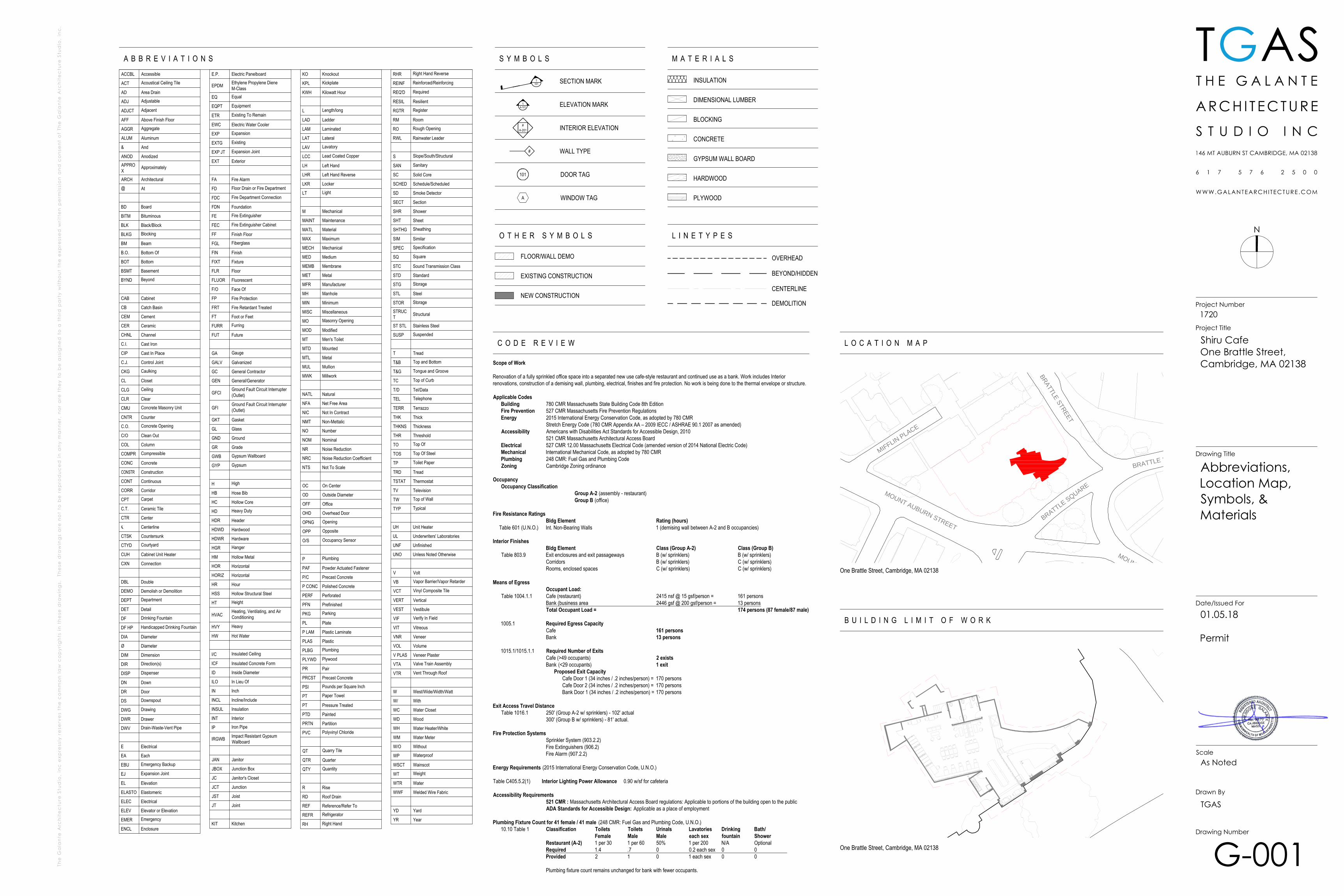
Scope of Work
Renovation of a fully sprinkled office space into a separated new use cafe-style restaurant and continued use as a bank. Work includes Interiorrenovations, construction of a demising wall, plumbing, electrical, finishes and fire protection. No work is being done to the thermal envelope or structure.
Applicable CodesBuilding 780 CMR Massachusetts State Building Code 8th EditionFire Prevention 527 CMR Massachusetts Fire Prevention RegulationsEnergy 2015 International Energy Conservation Code, as adopted by 780 CMR
Stretch Energy Code (780 CMR Appendix AA – 2009 IECC / ASHRAE 90.1 2007 as amended)Accessibility Americans with Disabilities Act Standards for Accessible Design, 2010
521 CMR Massachusetts Architectural Access BoardElectrical 527 CMR 12.00 Massachusetts Electrical Code (amended version of 2014 National Electric Code)Mechanical International Mechanical Code, as adopted by 780 CMRPlumbing 248 CMR: Fuel Gas and Plumbing CodeZoning Cambridge Zoning ordinance
OccupancyOccupancy Classification
Group A-2 (assembly - restaurant)Group B (office)
Fire Resistance RatingsBldg Element Rating (hours)
Table 601 (U.N.O.) Int. Non-Bearing Walls 1 (demising wall between A-2 and B occupancies)
Interior FinishesBldg Element Class (Group A-2) Class (Group B)
Table 803.9 Exit enclosures and exit passageways B (w/ sprinklers) B (w/ sprinklers)Corridors B (w/ sprinklers) C (w/ sprinklers)Rooms, enclosed spaces C (w/ sprinklers) C (w/ sprinklers)
Means of EgressOccupant Load:
Table 1004.1.1 Cafe (restaurant) 2415 nsf @ 15 gsf/person = 161 personsBank (business area 2446 gsf @ 200 gsf/person = 13 personsTotal Occupant Load = 174 persons (87 female/87 male)
1005.1 Required Egress CapacityCafe 161 personsBank 13 persons
1015.1/1015.1.1 Required Number of ExitsCafe (>49 occupants) 2 existsBank (<29 occupants) 1 exit
Proposed Exit CapacityCafe Door 1 (34 inches / .2 inches/person) = 170 personsCafe Door 2 (34 inches / .2 inches/person) = 170 personsBank Door 1 (34 inches / .2 inches/person) = 170 persons
Exit Access Travel DistanceTable 1016.1 250' (Group A-2 w/ sprinklers) - 102' actual
300' (Group B w/ sprinklers) - 81' actual.
Fire Protection SystemsSprinkler System (903.2.2)Fire Extinguishers (906.2)Fire Alarm (907.2.2)
Energy Requirements (2015 International Energy Conservation Code, U.N.O.)
Table C405.5.2(1) Interior Lighting Power Allowance 0.90 w/sf for cafeteria
Accessibility Requirements521 CMR : Massachusetts Architectural Access Board regulations: Applicable to portions of the building open to the publicADA Standards for Accessible Design: Applicable as a place of employment
Plumbing Fixture Count for 41 female / 41 male (248 CMR: Fuel Gas and Plumbing Code, U.N.O.)10.10 Table 1 Classification Toilets Toilets Urinals Lavatories Drinking Bath/
Female Male Male each sex fountain ShowerRestaurant (A-2) 1 per 30 1 per 60 50% 1 per 200 N/A OptionalRequired 1.4 .7 0 0.2 each sex 0 0Provided 2 1 0 1 each sex 0 0
Plumbing fixture count remains unchanged for bank with fewer occupants.
N
TGAS
Scale
Drawn By
Drawing Number
Date/Issued For
Drawing Title
Project Number
Project Title
01.05.18
Permit
Shiru CafeOne Brattle Street,Cambridge, MA 02138
1720
As Noted
TGAS
G-002
General Notes
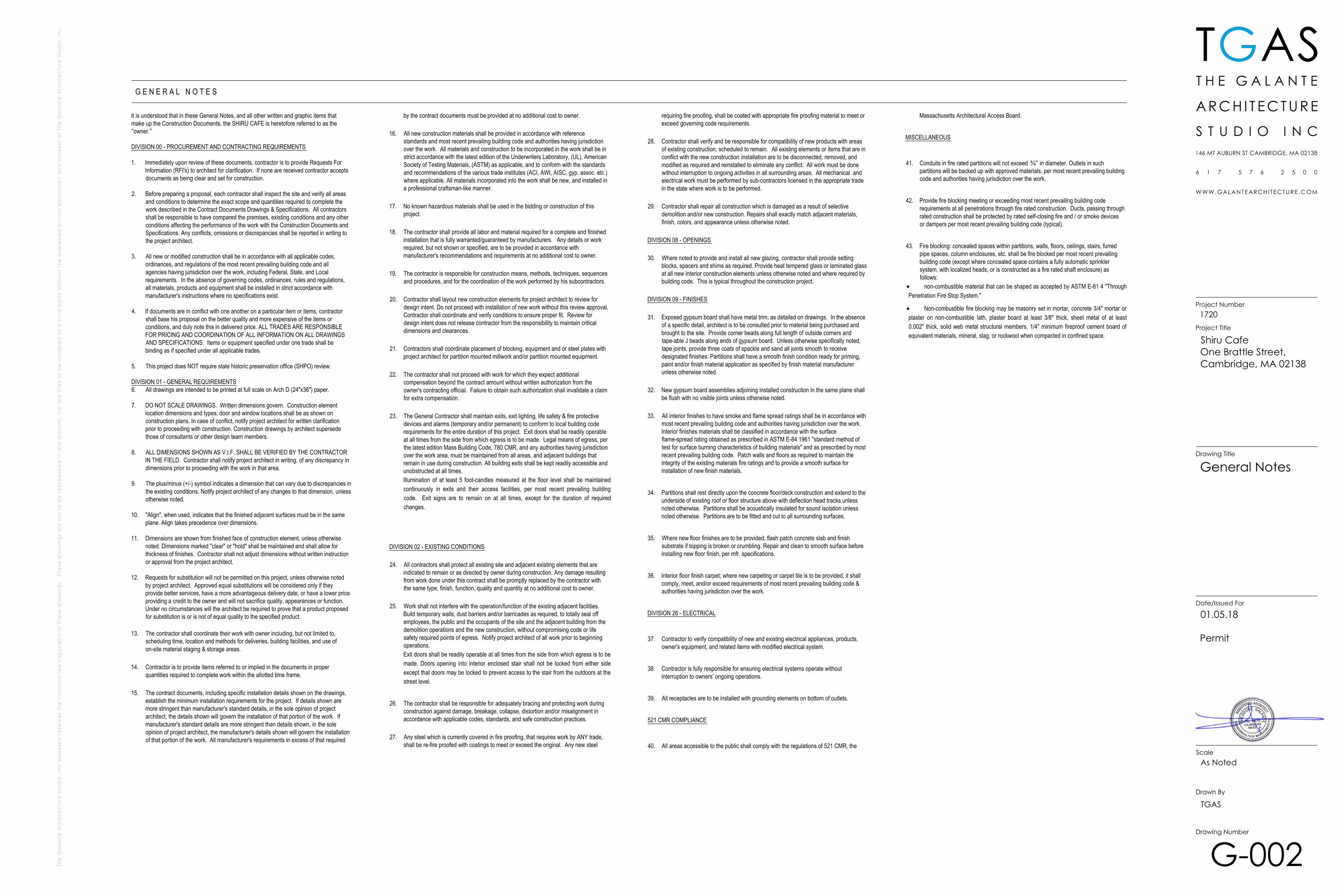
It is understood that in these General Notes, and all other written and graphic items thatmake up the Construction Documents, the SHIRU CAFE is heretofore referred to as the“owner.”
DIVISION 00 - PROCUREMENT AND CONTRACTING REQUIREMENTS
1. Immediately upon review of these documents, contractor is to provide Requests ForInformation (RFI's) to architect for clarification. If none are received contractor acceptsdocuments as being clear and set for construction.
2. Before preparing a proposal, each contractor shall inspect the site and verify all areasand conditions to determine the exact scope and quantities required to complete thework described in the Contract Documents Drawings & Specifications. All contractorsshall be responsible to have compared the premises, existing conditions and any otherconditions affecting the performance of the work with the Construction Documents andSpecifications. Any conflicts, omissions or discrepancies shall be reported in writing tothe project architect.
3. All new or modified construction shall be in accordance with all applicable codes,ordinances, and regulations of the most recent prevailing building code and allagencies having jurisdiction over the work, including Federal, State, and Localrequirements. In the absence of governing codes, ordinances, rules and regulations,all materials, products and equipment shall be installed in strict accordance withmanufacturer's instructions where no specifications exist.
4. If documents are in conflict with one another on a particular item or items, contractorshall base his proposal on the better quality and more expensive of the items orconditions, and duly note this in delivered price. ALL TRADES ARE RESPONSIBLEFOR PRICING AND COORDINATION OF ALL INFORMATION ON ALL DRAWINGSAND SPECIFICATIONS. Items or equipment specified under one trade shall bebinding as if specified under all applicable trades.
5. This project does NOT require state historic preservation office (SHPO) review.
DIVISION 01 - GENERAL REQUIREMENTS6. All drawings are intended to be printed at full scale on Arch D (24"x36") paper.
7. DO NOT SCALE DRAWINGS. Written dimensions govern. Construction elementlocation dimensions and types, door and window locations shall be as shown onconstruction plans. In case of conflict, notify project architect for written clarificationprior to proceeding with construction. Construction drawings by architect supersedethose of consultants or other design team members.
8. ALL DIMENSIONS SHOWN AS V.I.F. SHALL BE VERIFIED BY THE CONTRACTORIN THE FIELD. Contractor shall notify project architect in writing, of any discrepancy indimensions prior to proceeding with the work in that area.
9. The plus/minus (+/-) symbol indicates a dimension that can vary due to discrepancies inthe existing conditions. Notify project architect of any changes to that dimension, unlessotherwise noted.
10. "Align", when used, indicates that the finished adjacent surfaces must be in the sameplane. Align takes precedence over dimensions.
11. Dimensions are shown from finished face of construction element, unless otherwisenoted. Dimensions marked "clear" or "hold" shall be maintained and shall allow forthickness of finishes. Contractor shall not adjust dimensions without written instructionor approval from the project architect.
12. Requests for substitution will not be permitted on this project, unless otherwise notedby project architect. Approved equal substitutions will be considered only if theyprovide better services, have a more advantageous delivery date, or have a lower priceproviding a credit to the owner and will not sacrifice quality, appearances or function.Under no circumstances will the architect be required to prove that a product proposedfor substitution is or is not of equal quality to the specified product.
13. The contractor shall coordinate their work with owner including, but not limited to,scheduling time, location and methods for deliveries, building facilities, and use ofon-site material staging & storage areas.
14. Contractor is to provide items referred to or implied in the documents in properquantities required to complete work within the allotted time frame.
15. The contract documents, including specific installation details shown on the drawings,establish the minimum installation requirements for the project. If details shown aremore stringent than manufacturer's standard details, in the sole opinion of projectarchitect, the details shown will govern the installation of that portion of the work. Ifmanufacturer's standard details are more stringent than details shown, in the soleopinion of project architect, the manufacturer's details shown will govern the installationof that portion of the work. All manufacturer's requirements in excess of that required
by the contract documents must be provided at no additional cost to owner.
16. All new construction materials shall be provided in accordance with referencestandards and most recent prevailing building code and authorities having jurisdictionover the work. All materials and construction to be incorporated in the work shall be instrict accordance with the latest edition of the Underwriters Laboratory, (UL), AmericanSociety of Testing Materials, (ASTM) as applicable, and to conform with the standardsand recommendations of the various trade institutes (ACI, AWI, AISC, gyp. assoc. etc.)where applicable. All materials incorporated into the work shall be new, and installed ina professional craftsman-like manner.
17. No known hazardous materials shall be used in the bidding or construction of thisproject.
18. The contractor shall provide all labor and material required for a complete and finishedinstallation that is fully warranted/guaranteed by manufacturers. Any details or workrequired, but not shown or specified, are to be provided in accordance withmanufacturer's recommendations and requirements at no additional cost to owner.
19. The contractor is responsible for construction means, methods, techniques, sequencesand procedures, and for the coordination of the work performed by his subcontractors.
20. Contractor shall layout new construction elements for project architect to review fordesign intent. Do not proceed with installation of new work without this review approval.Contractor shall coordinate and verify conditions to ensure proper fit. Review fordesign intent does not release contractor from the responsibility to maintain criticaldimensions and clearances.
21. Contractors shall coordinate placement of blocking, equipment and or steel plates withproject architect for partition mounted millwork and/or partition mounted equipment.
22. The contractor shall not proceed with work for which they expect additionalcompensation beyond the contract amount without written authorization from theowner's contracting official. Failure to obtain such authorization shall invalidate a claimfor extra compensation.
23. The General Contractor shall maintain exits, exit lighting, life safety & fire protectivedevices and alarms (temporary and/or permanent) to conform to local building coderequirements for the entire duration of this project. Exit doors shall be readily operableat all times from the side from which egress is to be made. Legal means of egress, perthe latest edition Mass Building Code, 780 CMR, and any authorities having jurisdictionover the work area, must be maintained from all areas, and adjacent buildings thatremain in use during construction. All building exits shall be kept readily accessible andunobstructed at all times.Illumination of at least 5 foot-candles measured at the floor level shall be maintainedcontinuously in exits and their access facilities, per most recent prevailing buildingcode. Exit signs are to remain on at all times, except for the duration of requiredchanges.
DIVISION 02 - EXISTING CONDITIONS
24. All contractors shall protect all existing site and adjacent existing elements that areindicated to remain or as directed by owner during construction. Any damage resultingfrom work done under this contract shall be promptly replaced by the contractor withthe same type, finish, function, quality and quantity at no additional cost to owner.
25. Work shall not interfere with the operation/function of the existing adjacent facilities.Build temporary walls, dust barriers and/or barricades as required, to totally seal offemployees, the public and the occupants of the site and the adjacent building from thedemolition operations and the new construction, without compromising code or lifesafety required points of egress. Notify project architect of all work prior to beginningoperations.Exit doors shall be readily operable at all times from the side from which egress is to bemade. Doors opening into interior enclosed stair shall not be locked from either sideexcept that doors may be locked to prevent access to the stair from the outdoors at thestreet level.
26. The contractor shall be responsible for adequately bracing and protecting work duringconstruction against damage, breakage, collapse, distortion and/or misalignment inaccordance with applicable codes, standards, and safe construction practices.
27. Any steel which is currently covered in fire proofing, that requires work by ANY trade,shall be re-fire proofed with coatings to meet or exceed the original. Any new steel
requiring fire proofing, shall be coated with appropriate fire proofing material to meet orexceed governing code requirements.
28. Contractor shall verify and be responsible for compatibility of new products with areasof existing construction, scheduled to remain. All existing elements or items that are inconflict with the new construction installation are to be disconnected, removed, andmodified as required and reinstalled to eliminate any conflict. All work must be donewithout interruption to ongoing activities in all surrounding areas. All mechanical andelectrical work must be performed by sub-contractors licensed in the appropriate tradein the state where work is to be performed.
29. Contractor shall repair all construction which is damaged as a result of selectivedemolition and/or new construction. Repairs shall exactly match adjacent materials,finish, colors, and appearance unless otherwise noted.
DIVISION 08 - OPENINGS
30. Where noted to provide and install all new glazing, contractor shall provide settingblocks, spacers and shims as required. Provide heat tempered glass or laminated glassat all new interior construction elements unless otherwise noted and where required bybuilding code. This is typical throughout the construction project.
DIVISION 09 - FINISHES
31. Exposed gypsum board shall have metal trim, as detailed on drawings. In the absenceof a specific detail, architect is to be consulted prior to material being purchased andbrought to the site. Provide corner beads along full length of outside corners andtape-able J beads along ends of gypsum board. Unless otherwise specifically noted,tape joints, provide three coats of spackle and sand all joints smooth to receivedesignated finishes. Partitions shall have a smooth finish condition ready for priming,paint and/or finish material application as specified by finish material manufacturerunless otherwise noted.
32. New gypsum board assemblies adjoining installed construction in the same plane shallbe flush with no visible joints unless otherwise noted.
33. All interior finishes to have smoke and flame spread ratings shall be in accordance withmost recent prevailing building code and authorities having jurisdiction over the work.Interior finishes materials shall be classified in accordance with the surfaceflame-spread rating obtained as prescribed in ASTM E-84 1961 "standard method oftest for surface burning characteristics of building materials" and as prescribed by mostrecent prevailing building code. Patch walls and floors as required to maintain theintegrity of the existing materials fire ratings and to provide a smooth surface forinstallation of new finish materials.
34. Partitions shall rest directly upon the concrete floor/deck construction and extend to theunderside of existing roof or floor structure above with deflection head tracks unlessnoted otherwise. Partitions shall be acoustically insulated for sound isolation unlessnoted otherwise. Partitions are to be fitted and cut to all surrounding surfaces.
35. Where new floor finishes are to be provided, flash patch concrete slab and finishsubstrate if topping is broken or crumbling. Repair and clean to smooth surface beforeinstalling new floor finish, per mfr. specifications.
36. Interior floor finish carpet; where new carpeting or carpet tile is to be provided, it shallcomply, meet, and/or exceed requirements of most recent prevailing building code &authorities having jurisdiction over the work.
DIVISION 26 - ELECTRICAL
37. Contractor to verify compatibility of new and existing electrical appliances, products,owner's equipment, and related items with modified electrical system.
38. Contractor is fully responsible for ensuring electrical systems operate withoutinterruption to owners' ongoing operations.
39. All receptacles are to be installed with grounding elements on bottom of outlets.
521 CMR COMPLIANCE
40. All areas accessible to the public shall comply with the regulations of 521 CMR, the
Massachusetts Architectural Access Board.
MISCELLANEOUS
41. Conduits in fire rated partitions will not exceed ¾” in diameter. Outlets in suchpartitions will be backed up with approved materials, per most recent prevailing buildingcode and authorities having jurisdiction over the work.
42. Provide fire blocking meeting or exceeding most recent prevailing building coderequirements at all penetrations through fire rated construction. Ducts, passing throughrated construction shall be protected by rated self-closing fire and / or smoke devicesor dampers per most recent prevailing building code (typical).
43. Fire blocking: concealed spaces within partitions, walls, floors, ceilings, stairs, furredpipe spaces, column enclosures, etc. shall be fire blocked per most recent prevailingbuilding code (except where concealed space contains a fully automatic sprinklersystem, with localized heads, or is constructed as a fire rated shaft enclosure) asfollows:
non-combustible material that can be shaped as accepted by ASTM E-81 4 "ThroughPenetration Fire Stop System."
Non-combustible fire blocking may be masonry set in mortar, concrete 3/4" mortar orplaster on non-combustible lath, plaster board at least 3/8" thick, sheet metal of at least0.002" thick, solid web metal structural members, 1/4" minimum fireproof cement board ofequivalent materials, mineral, slag, or rockwool when compacted in confined space.
G E N E R A L N O T E S
TGAS
Scale
Drawn By
Drawing Number
Date/Issued For
Drawing Title
Project Number
Project Title
01.05.18
Permit
Shiru CafeOne Brattle Street,Cambridge, MA 02138
1720
7 8
8.1 910
A
9.1
6 6.15
A2
B
B1
B2
A1
C
12'-2
5 8"
7'-414"
12'-8
1 4"
8'-618" 1'-
9"
2'-3 38"
12'-1
3 8"
9'-9 58"
6'-8"
9'-53 4"
834"
3'-2"
13'-11"
15'-6
1 4"
10'-4
"6'-
51 8"
5'-4 78"
9"
5"
1'-4"
0"
6'-718"
2'-11
3 4"
2'-11
1 8"
2'-0"
2'-01 4"
4'-10
1 4"
5'-2"
20'-2
"
31'-1
11 2"
5'-512"51 4"
4'-81 2"
15'-1
3 8"
4'-614"
7'-0"
22'-814"
7'-8"
2'-6"
11'-6"
3'-6"2'-6"
3'-13 8"
13'-1
01 2"
28'-21 2"
10'-4
1 8"
17'-818"
6'-45
8"
20'-112"
4'-338"
2'-6"
5'-2"
6'-71 2"
1'-11 2"
2'-7"
26'-5"
4'-93
8"
13'-11"
15'-434"
3'-0"
5'-0"
111 2"
2'-11
"
4'-5"
8'-6"
3'-812"
5'-0"
11'-10"
wall heater
wall heater
4'-93
8"
10'-0"
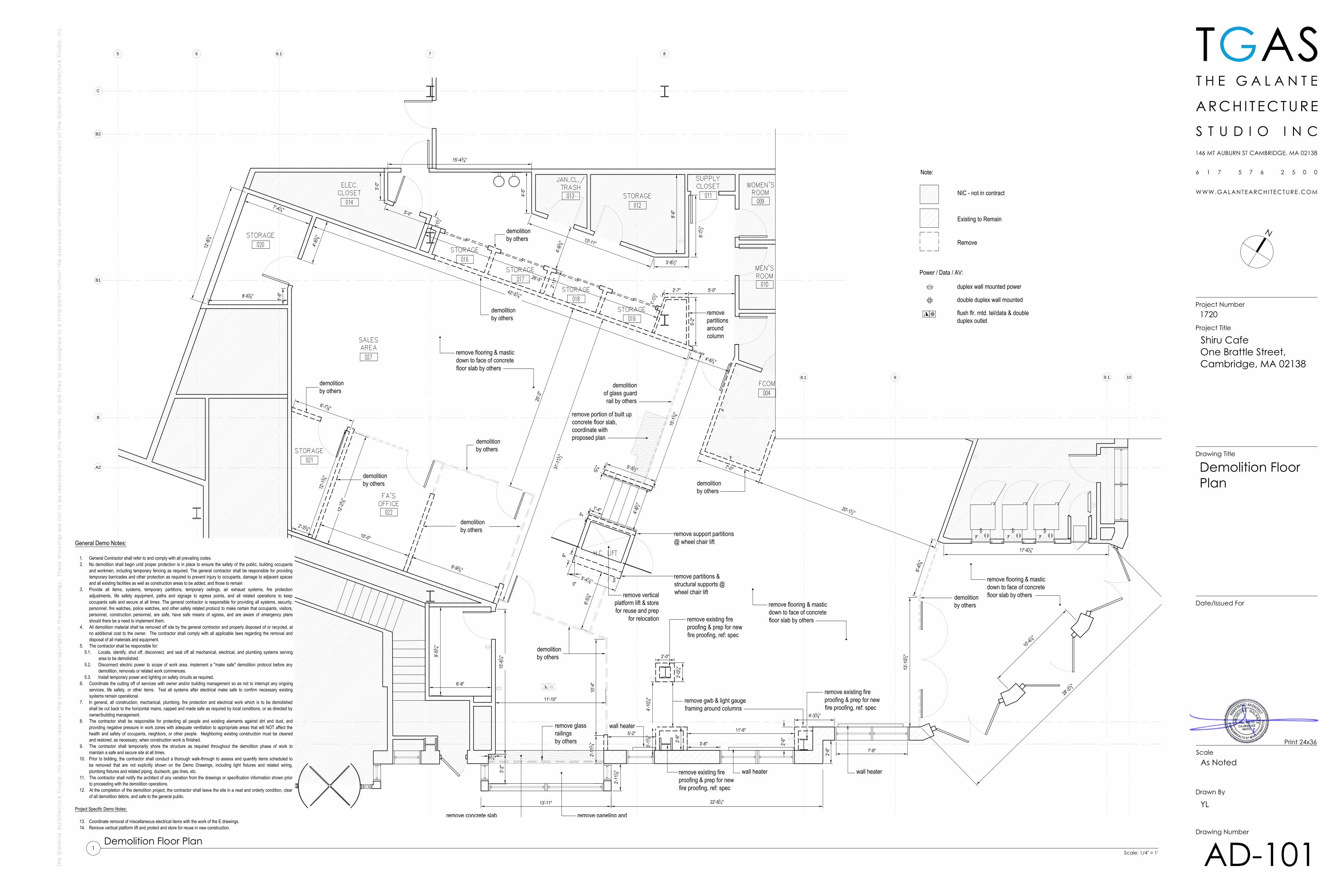
NIC - not in contract
Existing to Remain
Remove
Note:
duplex wall mounted power
double duplex wall mounted
Power / Data / AV:
flush flr. mtd. tel/data & doubleduplex outlet
remove glassrailingsby others
remove gwb & light gaugeframing around columns
demolitionby others
remove support partitions@ wheel chair lift
demolitionby others
removepartitionsaroundcolumn
demolitionby others
demolitionby others
demolitionby others
demolitionby others
demolitionby others
demolitionby others
demolitionof glass guardrail by others
demolitionby others
wall heater
remove partitions &structural supports @wheel chair lift
remove flooring & masticdown to face of concretefloor slab by others
remove flooring & masticdown to face of concretefloor slab by others
remove verticalplatform lift & storefor reuse and prep
for relocation
remove existing fireproofing & prep for newfire proofing, ref: spec
remove existing fireproofing & prep for newfire proofing, ref: spec
remove existing fireproofing & prep for newfire proofing, ref: spec
remove flooring & masticdown to face of concretefloor slab by others
remove portion of built upconcrete floor slab,coordinate withproposed plan
42'-5 78"
remove concrete slab remove paneling and
N
TGAS
Scale
Drawn By
Drawing Number
Date/Issued For
Drawing Title
Project Number
Project Title
Shiru CafeOne Brattle Street,Cambridge, MA 02138
1720
As Noted
YL
AD-101
Demolition FloorPlan
Print 24x36
Scale: 1/4" = 1'
Demolition Floor Plan1
General Demo Notes:
1. General Contractor shall refer to and comply with all prevailing codes.2. No demolition shall begin until proper protection is in place to ensure the safety of the public, building occupants
and workmen, including temporary fencing as required. The general contractor shall be responsible for providingtemporary barricades and other protection as required to prevent injury to occupants, damage to adjacent spacesand all existing facilities as well as construction areas to be added, and those to remain
3. Provide all items, systems, temporary partitions, temporary ceilings, air exhaust systems, fire protectionadjustments, life safety equipment, paths and signage to egress points, and all related operations to keepoccupants safe and secure at all times. The general contractor is responsible for providing all systems, security,personnel, fire watches, police watches, and other safety related protocol to make certain that occupants, visitors,personnel, construction personnel, are safe, have safe means of egress, and are aware of emergency plansshould there be a need to implement them.
4. All demolition material shall be removed off site by the general contractor and properly disposed of or recycled, atno additional cost to the owner. The contractor shall comply with all applicable laws regarding the removal anddisposal of all materials and equipment.
5. The contractor shall be responsible for:5.1. Locate, identify, shut off, disconnect, and seal off all mechanical, electrical, and plumbing systems serving
area to be demolished.5.2. Disconnect electric power to scope of work area, implement a "make safe" demolition protocol before any
demolition, removals or related work commences.5.3. Install temporary power and lighting on safety circuits as required.
6. Coordinate the cutting off of services with owner and/or building management so as not to interrupt any ongoingservices, life safety, or other items. Test all systems after electrical make safe to confirm necessary existingsystems remain operational.
7. In general, all construction, mechanical, plumbing, fire protection and electrical work which is to be demolishedshall be cut back to the horizontal mains, capped and made safe as required by local conditions, or as directed byowner/building management.
8. The contractor shall be responsible for protecting all people and existing elements against dirt and dust, andproviding negative pressure in work zones with adequate ventilation to appropriate areas that will NOT affect thehealth and safety of occupants, neighbors, or other people. Neighboring existing construction must be cleanedand restored, as necessary, when construction work is finished.
9. The contractor shall temporarily shore the structure as required throughout the demolition phase of work tomaintain a safe and secure site at all times.
10. Prior to bidding, the contractor shall conduct a thorough walk-through to assess and quantify items scheduled tobe removed that are not explicitly shown on the Demo Drawings, including light fixtures and related wiring,plumbing fixtures and related piping, ductwork, gas lines, etc.
11. The contractor shall notify the architect of any variation from the drawings or specification information shown priorto proceeding with the demolition operations.
12. At the completion of the demolition project, the contractor shall leave the site in a neat and orderly condition, clearof all demolition debris, and safe to the general public.
Project Specific Demo Notes:
13. Coordinate removal of miscellaneous electrical items with the work of the E drawings.14. Remove vertical platform lift and protect and store for reuse in new construction.
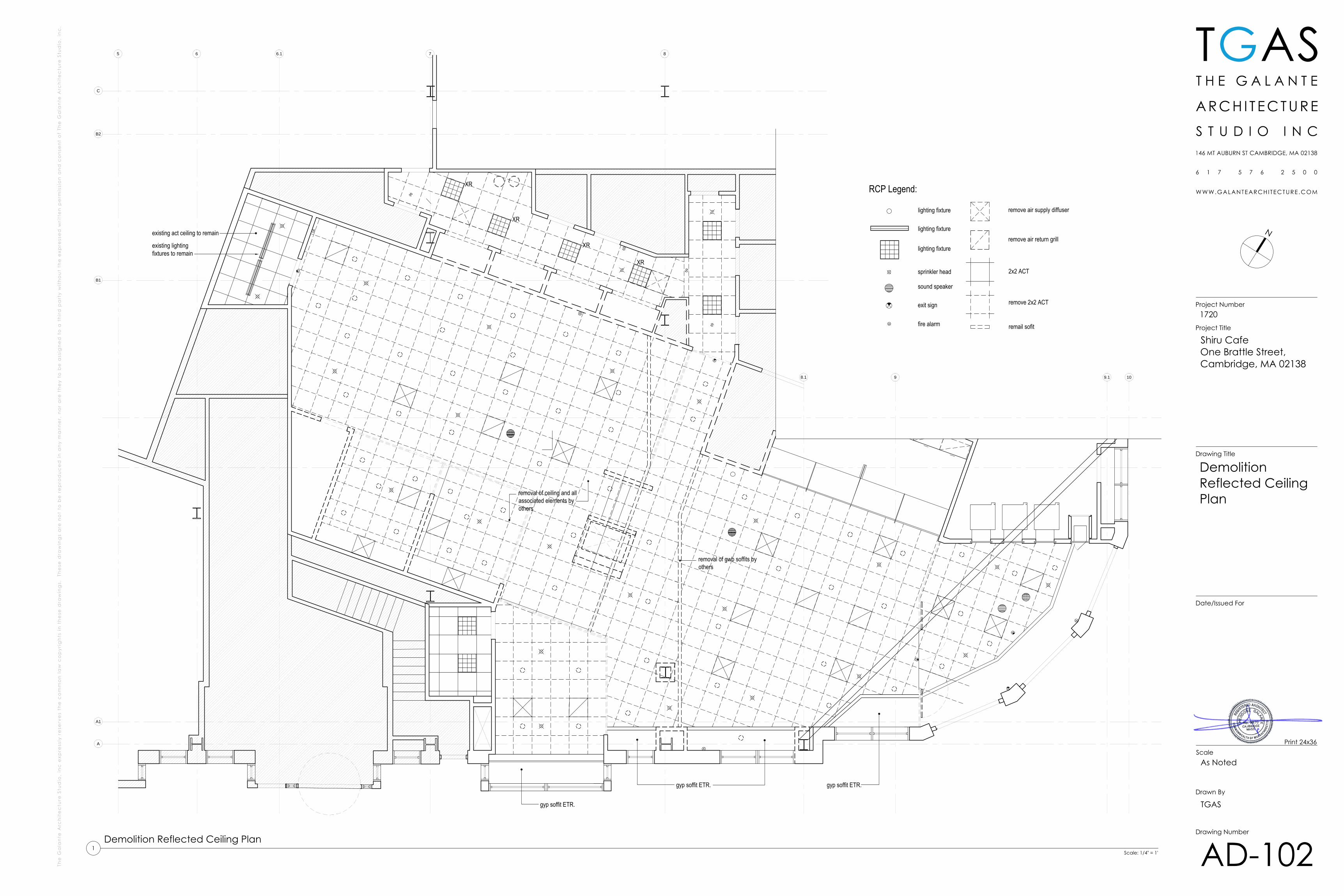
lighting fixture
2x2 ACT
RCP Legend:
sprinkler head
exit sign
remove air supply diffuser
sound speaker
remove air return grill
fire alarm
lighting fixture
lighting fixture
7 8
8.1 9 10
A
9.1
6 6.15
B1
B2
A1
C
remove 2x2 ACT
remail sofit
XR
XR
XR
XR
gyp soffit ETR. gyp soffit ETR.
existing act ceiling to remain
existing lightingfixtures to remain
gyp soffit ETR.
removal of ceiling and allassociated elements byothers
removal of gwb soffits byothers
N
TGAS
Scale
Drawn By
Drawing Number
Date/Issued For
Drawing Title
Project Number
Project Title
Shiru CafeOne Brattle Street,Cambridge, MA 02138
1720
As Noted
TGAS
AD-102
DemolitionReflected CeilingPlan
Print 24x36
Scale: 1/4" = 1'
Demolition Reflected Ceiling Plan1
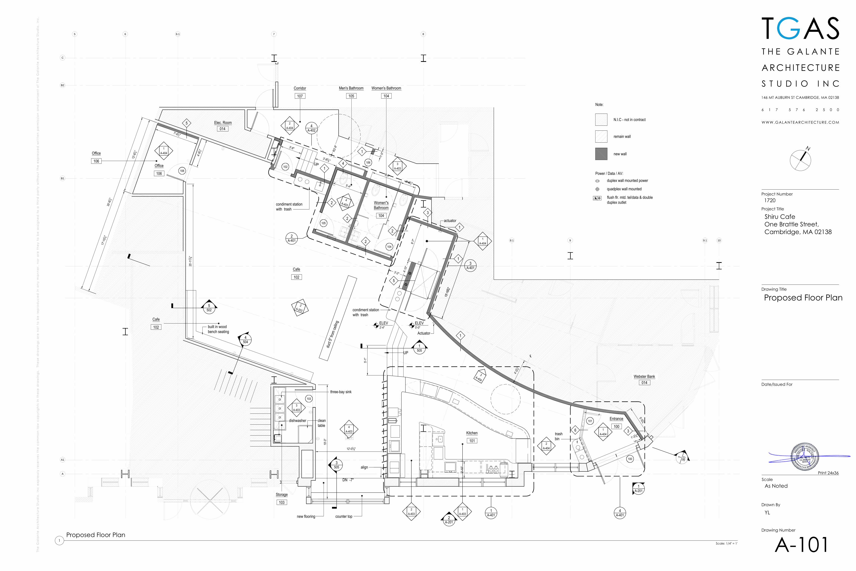
Note:
N.I.C - not in contract
remain wall
new wall
duplex wall mounted power
quadplex wall mounted
Power / Data / AV:
flush flr. mtd. tel/data & doubleduplex outlet
2'-10
"
2A-201
1A-201
Office
106
Cafe
102
Men's Bathroom
105
Women's Bathroom
104
Storage
103
duct
5" fro
m ce
iling
7 8
8.1 9 10
A
9.1
6 6.1
B1
B2
A1
C
13'-1
014"
5'-4"
three-bay sink
dishwasher cleantable
1A-401
100
101
103
105
104
102106
Women"sBathroom
104
Office
106
D B
C
A
3A-403
D B
C
A
2A-404
5
Corridor
107
106
D B
C
A
1A-403
D B
C
A
3A-403
D B
C
A
2A-403
5502
Entrance
100
4A-4032
2
2
1
3
1
4
2A-203
3
1
1
4504
3505
3A-404
D B
C
A
1A-404
D B
C
A
4A-403
3'-2"
13'-1
014"
4'-10
"
1'-0"
align
5'-5 14 "
2
12'-038"
5'-1"
6'-7"
1505
ELEV2'-4"
ELEV0'-0"
D B
C
A
1A-404
Kitchen
101
Cafe
102
D B
C
A
2A-404
2A-401
D B
C
A
1A-404
4A-402
3A-401
actuator
Actuator
1'-33 8"
4A-401
19'-3
"
4'-91 4"
12'-8
1 4"
17'-1
014"
25'-1
13 8"
30'-6
1 2"
7'-412"
trashbin
condiment stationwith trash
condiment stationwith trash
UP
4'-21 8"
℄
2'-612"
5'-0"
UP3'-8 5
8"
R3'-8
"3'-8"
5
counter top
DN -7"
130
1
1'-7"
0"
built in woodbench seating
014Elec. Room5
014Webster Bank
6
1
new flooring
N
TGAS
Scale
Drawn By
Drawing Number
Date/Issued For
Drawing Title
Project Number
Project Title
Shiru CafeOne Brattle Street,Cambridge, MA 02138
1720
As Noted
YL
A-101
Proposed Floor Plan
Print 24x36
Scale: 1/4" = 1'
Proposed Floor Plan1
P1
2'-0"
6'-0"
7'-9"
5'-3"
5'-3"
3'-8" (typ)
3'-1"
3'-4"
1'-3"
T1L1
L1
L1
L1
L1
L1
L1
L1
L1
L1
L1L1
L1 L1
L1
L1
L1
L1
L1
L1
L1
L1
L1
L1
L1
L1
L1
L1L1
L1
L1
L1 L1
3'-0" (typ)
2A-201
1A-201
T2
11'-3"
xm
xm
xm
xm
xr
xr
xr
xr
xr
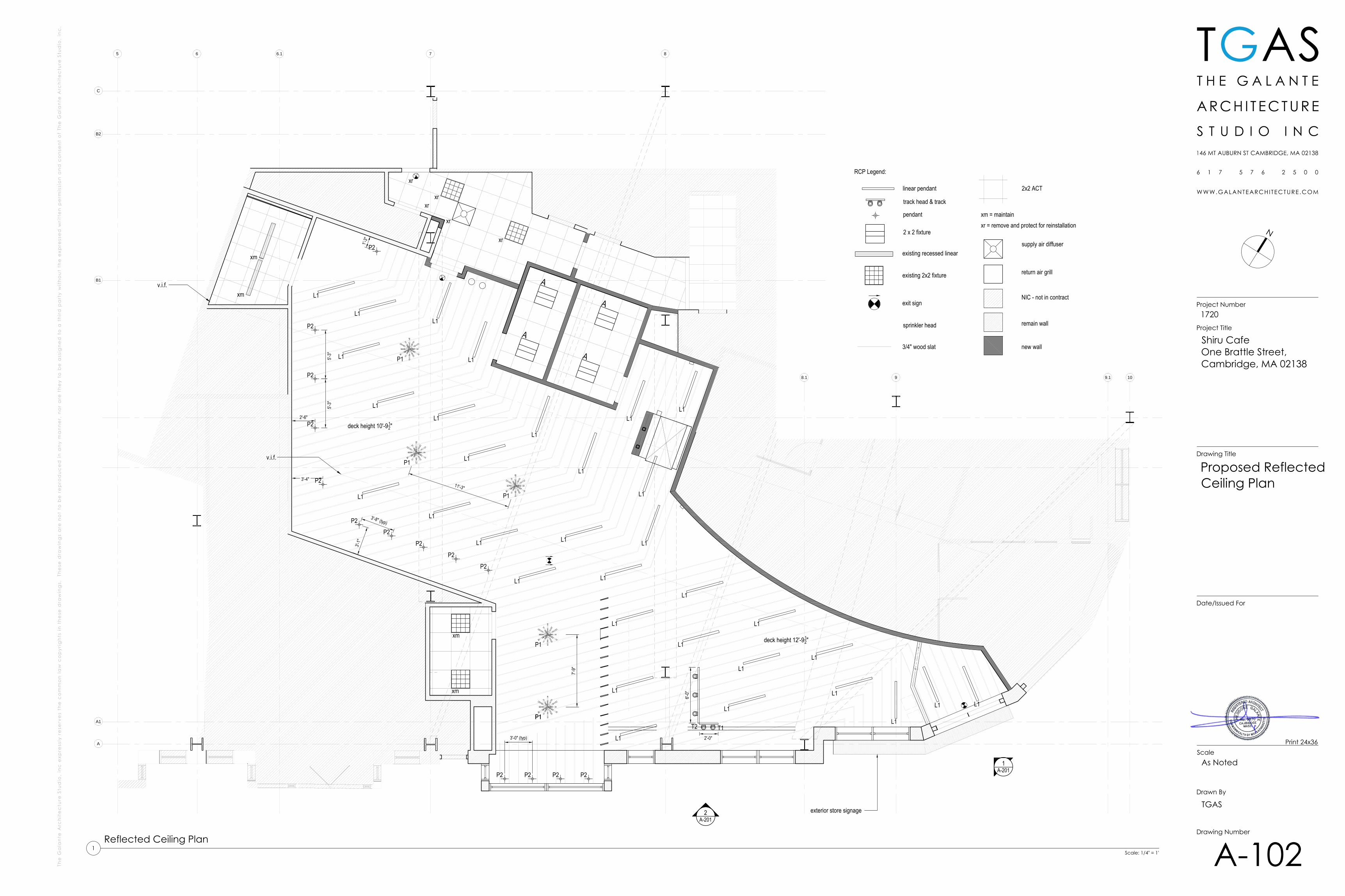
deck height 12'-912"
deck height 10'-912"
v.i.f.
v.i.f.
2'-6"
7 8
8.1 9 10
A
9.1
6 6.1
B1
B2
A1
C
pendant
linear pendant
track head & track
existing recessed linear
2x2 ACT
RCP Legend:
existing 2x2 fixture
3/4" wood slat
2 x 2 fixture
sprinkler head
xr = remove and protect for reinstallationxm = maintain
supply air diffuser
NIC - not in contract
remain wall
new wall
return air grill
5
exit sign
exterior store signage
P1
P1
P1
P1
P1
P2
P2
P2
P2
P2
P2
P2
P2
P2
P2
P2 P2 P2 P2
N
TGAS
Scale
Drawn By
Drawing Number
Date/Issued For
Drawing Title
Project Number
Project Title
Shiru CafeOne Brattle Street,Cambridge, MA 02138
1720
As Noted
TGAS
A-102
Proposed ReflectedCeiling Plan
Print 24x36
Scale: 1/4" = 1'
Reflected Ceiling Plan1
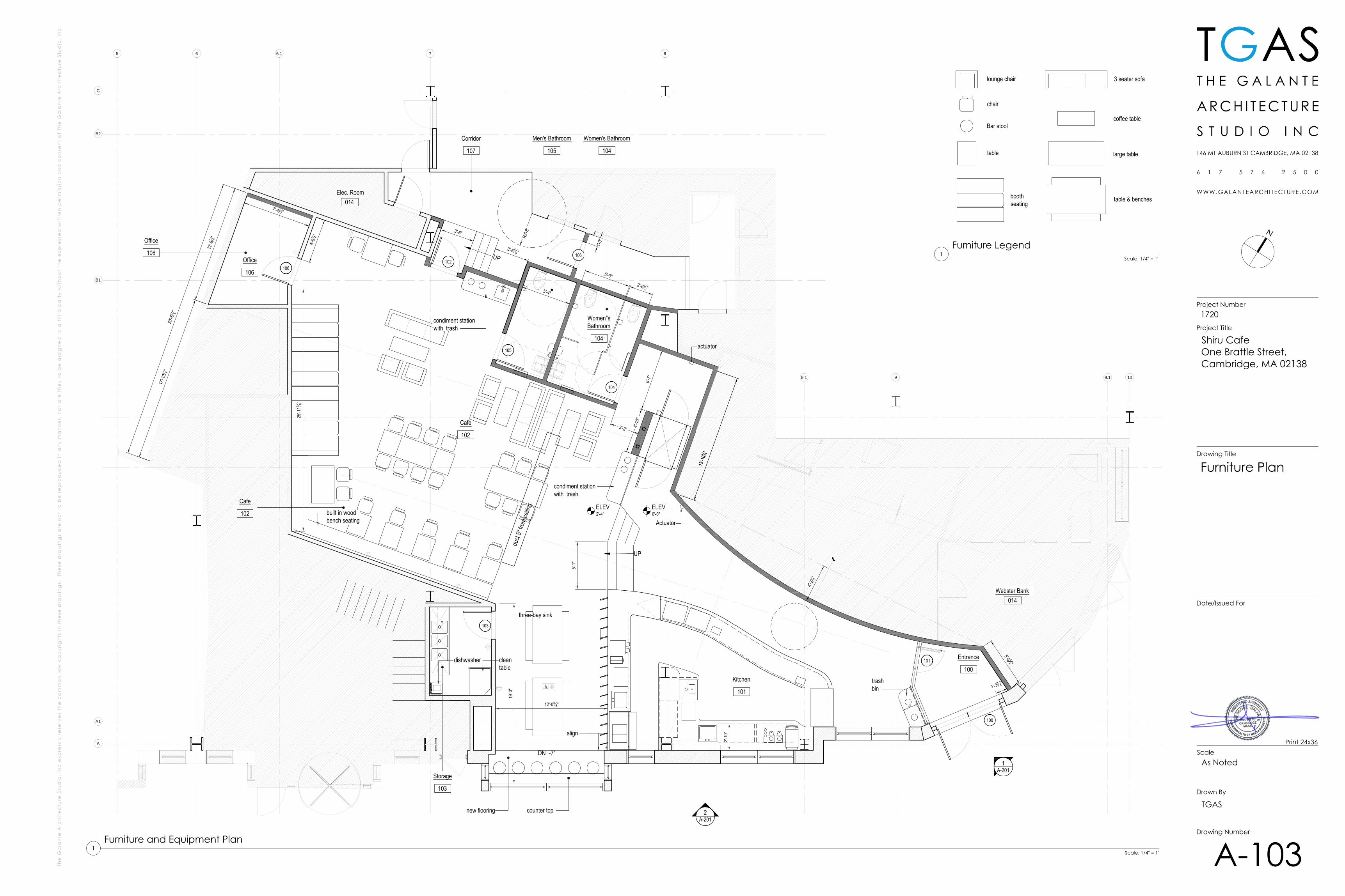
coffee table
table & benchesboothseating
lounge chair 3 seater sofa
chair
Bar stool
table large table
2'-10
"
2A-201
1A-201
Office
106
Cafe
102
Men's Bathroom
105
Women's Bathroom
104
Storage
103
duct
5" fro
m ce
iling
7 8
8.1 9 10
A
9.1
6 6.1
B1
B2
A1
C
13'-1
014"
5'-4"
three-bay sink
dishwasher cleantable
100
101
103
105
104
102106
Women"sBathroom
104
Office
106
Corridor
107
106
Entrance
100
3'-2"
13'-1
014"
4'-10
"
1'-0"
align
5'-5 14 "
12'-038"
5'-1"
6'-7"
ELEV2'-4"
ELEV0'-0"
Kitchen
101
Cafe
102
actuator
Actuator
1'-33 8"
19'-3
"
4'-91 4"
12'-8
1 4"
17'-1
014"
25'-1
13 8"
30'-6
1 2"
7'-412"
trashbin
condiment stationwith trash
condiment stationwith trash
UP
4'-21 8"
℄
2'-612"
5'-0"
UP3'-8 5
8"
R3'-8
"3'-8"
5
counter top
DN -7"
1'-7"
0"
built in woodbench seating
014Elec. Room
014Webster Bank
new flooring
N
TGAS
Scale
Drawn By
Drawing Number
Date/Issued For
Drawing Title
Project Number
Project Title
Shiru CafeOne Brattle Street,Cambridge, MA 02138
1720
As Noted
TGAS
A-103
Furniture Plan
Print 24x36
Scale: 1/4" = 1'
Furniture and Equipment Plan1
Scale: 1/4" = 1'
Furniture Legend1
9'-1"
1'-5"2'-
6"8"
1A-201
ground level0'-0"
second floor
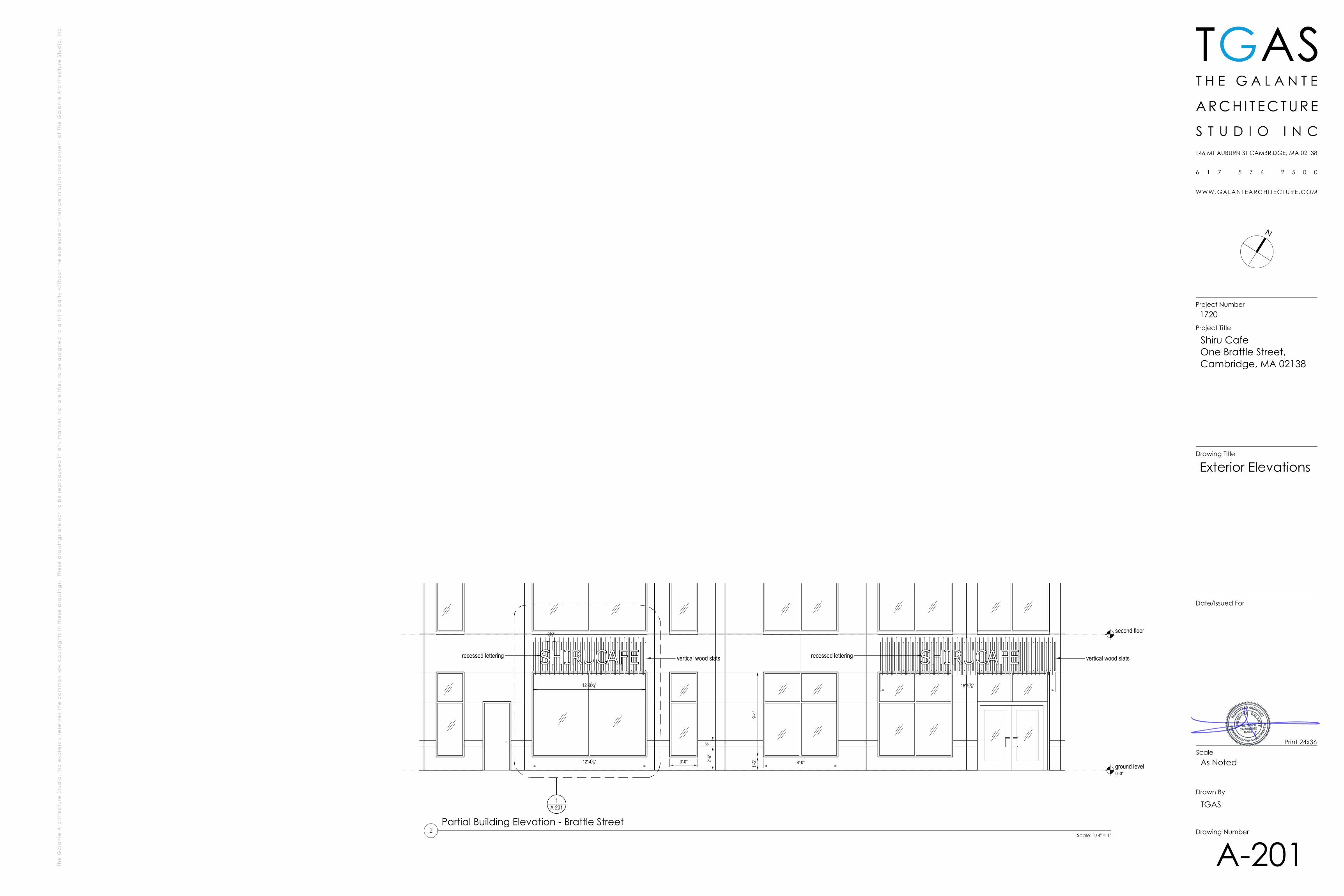
8'-0"3'-0"12'-418"
vertical wood slatsvertical wood slats recessed letteringrecessed lettering
214"
12'-034" 18'-91
8"
N
TGAS
Scale
Drawn By
Drawing Number
Date/Issued For
Drawing Title
Project Number
Project Title
Shiru CafeOne Brattle Street,Cambridge, MA 02138
1720
As Noted
TGAS
A-201
Exterior Elevations
Print 24x36
Scale: 1/4" = 1'
Partial Building Elevation - Brattle Street2
ylaakso
Rectangle
B.O. wood slats7'-11"
upper cafe level2'-0"
existing beam31.5"(h) x 30"(w)
existing beam19"(h) x 7"(w)
existing heat pump21"(h) x 33"(w) (V.I.F)
existing beam32"(h) x 12"(w)
existing beam33"(h) x 12"(w)
8'-2"9'-
21 2" 10'-9
1 2"
9'-61 2"
10'-0
1 2"
6" electrical conduit -9" above existing drop ceiling (V.I.F.)
12'-9
1 2"
8'-9"
8'-2" 9'-
21 2"
9'-61 2" 12
'-91 2"
10'-1
1 2"
10'-0
1 2"
existing beam33"(h) x 12"(w)
existing beam32"(h) x 12"(w)
existing beam39"(h) x 28"(w)
existing beam31.5"(h) x 30"(w)
existing beam19"(h) x 7"(w)
6" electrical conduit -9" above existing drop ceiling (V.I.F.)
10'-1
1 2"
ground level0'-0"
B.O. deck12'-9 1/2"
ground level0'-0"
upper cafe level2'-0"
bottom of deck12'-9 1/2"
7 8 8.1
9
9
788.1
9'-4"
7'-9"
8'-6"
b.o.
wood
slats
9'-11
"
10'-5
" 8'-9"
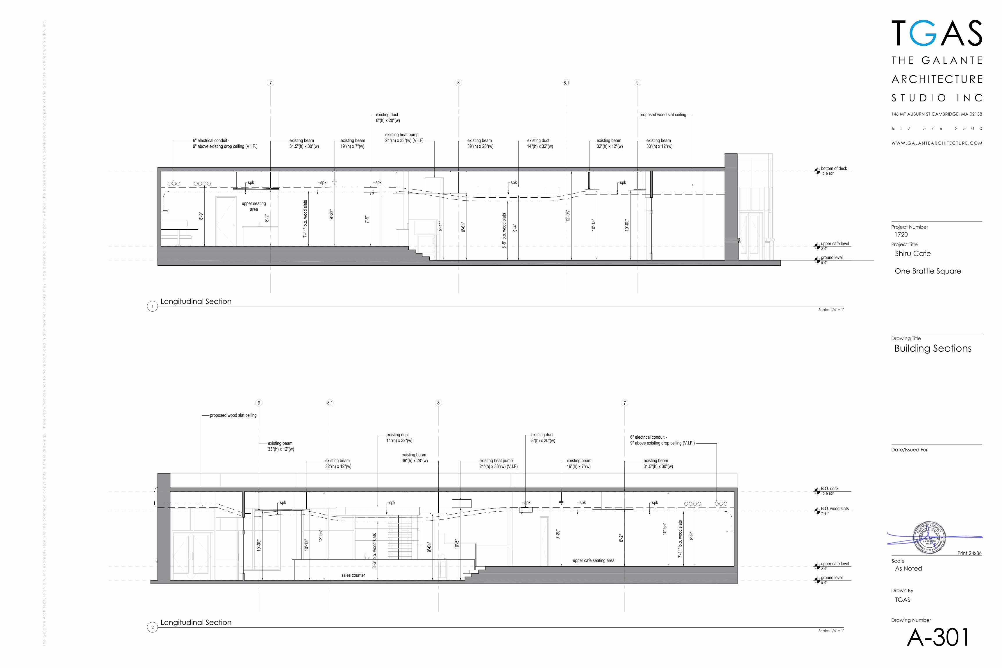
existing duct8"(h) x 20"(w)
existing heat pump21"(h) x 33"(w) (V.I.F) existing duct
14"(h) x 32"(w)
spkspkspkspkspk
proposed wood slat ceiling
proposed wood slat ceiling
spkspkspkspkspk
existing beam39"(h) x 28"(w)
existing duct8"(h) x 20"(w)
existing duct14"(h) x 32"(w)
upper cafe seating area
sales counter
7'-11
" b.o.
woo
d slat
s
7'-11
" b.o.
woo
d slat
supper seatingarea
8'-6"
b.o.
wood
slats
TGAS
Scale
Drawn By
Drawing Number
Date/Issued For
Drawing Title
Project Number
Project Title
1720
Shiru Cafe
One Brattle Square
As Noted
TGAS
A-301
Building Sections
Print 24x36
Scale: 1/4" = 1'
Longitudinal Section2
Scale: 1/4" = 1'
Longitudinal Section1
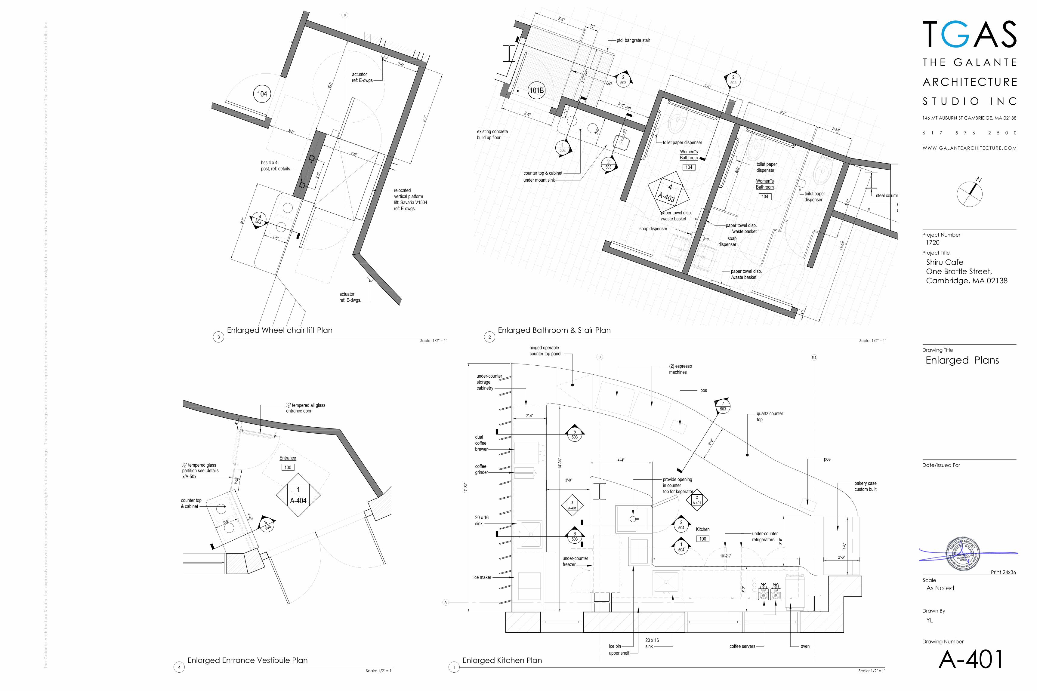
bakery casecustom built
pos
oven
(2) espressomachines
coffee servers
20 x 16sink
under-counterfreezer
pos
under-counterrefrigerators
provide openingin countertop for kegerator
quartz countertop
D B
C
A
2A-401
D B
C
A
3A-401
Kitchen
100
3'-0"
10'-278"
ice bin
ice maker
upper shelf
17'-3
1 8"
14'-3
5 8"
dualcoffeebrewer
under-counterstoragecabinetry
2'-4"
3'-2"
4'-4"
3'-6"
8
A
coffeegrinder
20 x 16sink
8.1
2'-6"
2'-6"
4'-0"
5503
7503
6503
2504
hinged operablecounter top panel
1504
5'-4"101B
Women"sBathroom
104
4A-403
1503
2'-6 12 "
5'-0"
UP
3'-8"11"
Women"sBathroom
104
11'-0
1 2"
6'-0"
2503
25023-1
0" m
in.
3'-8" min.
toilet paper dispenser
paper towel disp./waste basket
soap dispenser
paper towel disp./waste basket
paper towel disp./waste basket
soapdispenser
toilet paperdispenser
toilet paperdispenser
5'-2"
4"
under mount sink
11"
3'-8"
counter top & cabinet
ptd. bar grate stair
2'-0"
2505
existing concretebuild up floor
steel column ETRedge of existing builtup concrete floor
104
8
actuatorref: E-dwgs
actuatorref: E-dwgs.
1'-8"5'-
7"
3'-2"
6'-7"
4'-6"
hss 4 x 4post, ref: details
2'-0"
relocatedvertical platformlift: Savaria V1504ref: E-dwgs.
2'-6"
6'-7"
4503
Entrance
100
D B
C
A
1A-404
3503
1'-8"
1'-61 2"
4"
12" tempered glass
partition see: detailsx/A-50x
4'-4 12 "
12" tempered all glass
entrance door
counter top& cabinet
N
TGAS
Scale
Drawn By
Drawing Number
Date/Issued For
Drawing Title
Project Number
Project Title
Shiru CafeOne Brattle Street,Cambridge, MA 02138
1720
As Noted
YL
A-401
Enlarged Plans
Print 24x36
Scale: 1/2" = 1'
Enlarged Kitchen Plan1
Scale: 1/2" = 1'
Enlarged Bathroom & Stair Plan2
Scale: 1/2" = 1'
Enlarged Wheel chair lift Plan3
Scale: 1/2" = 1'
Enlarged Entrance Vestibule Plan4
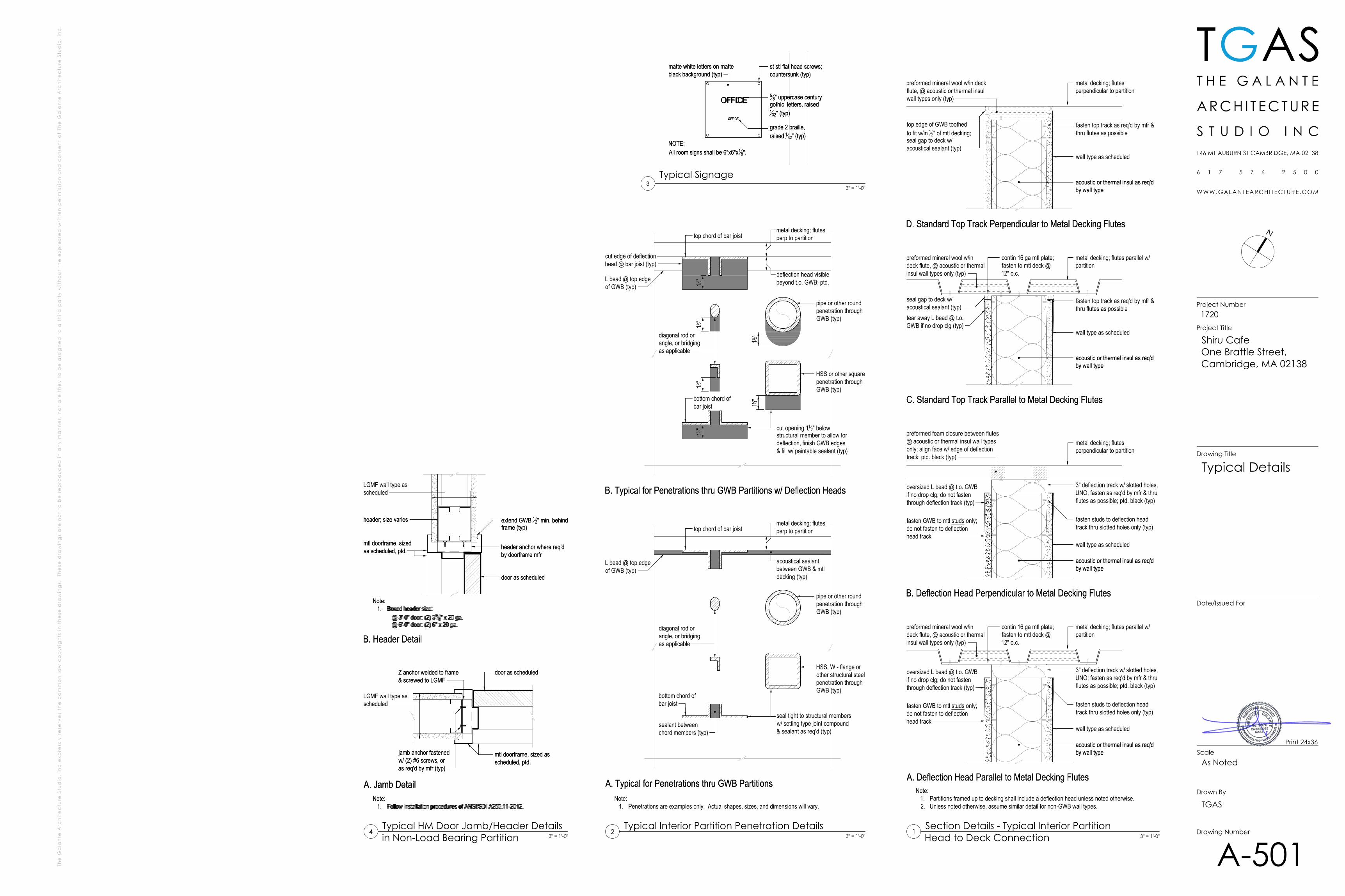
NOTE:All room signs shall be 6"x6"x1
8".
matte white letters on matteblack background (typ)
grade 2 braille,raised 132" (typ)
st stl flat head screws;countersunk (typ)
58" uppercase century
gothic letters, raised1
32" (typ)
58" uppercase century
gothic letters, raised1
32" (typ)
st stl flat head screws;countersunk (typ)
grade 2 braille,raised 132" (typ)
matte white letters on matteblack background (typ)
NOTE:All room signs shall be 6"x6"x1
8".
Note:1. Follow installation procedures of ANSI/SDI A250.11-2012.
A. Jamb Detail
jamb anchor fastenedw/ (2) #6 screws, oras req'd by mfr (typ)
Z anchor welded to frame& screwed to LGMF
mtl doorframe, sized asscheduled, ptd.
door as scheduled
LGMF wall type asscheduled
B. Header Detail
Note:1. Boxed header size:
@ 3'-0" door: (2) 358" x 20 ga.
@ 6'-0" door: (2) 6" x 20 ga.
header; size varies
header anchor where req'dby doorframe mfr
mtl doorframe, sizedas scheduled, ptd.
LGMF wall type asscheduled
extend GWB 12" min. behindframe (typ)
door as scheduleddoor as scheduled
extend GWB 12" min. behindframe (typ)
LGMF wall type asscheduled
mtl doorframe, sizedas scheduled, ptd. header anchor where req'd
by doorframe mfr
header; size varies
Note:1. Boxed header size:
@ 3'-0" door: (2) 358" x 20 ga.
@ 6'-0" door: (2) 6" x 20 ga.
B. Header Detail
LGMF wall type asscheduled
door as scheduled
mtl doorframe, sized asscheduled, ptd.
Z anchor welded to frame& screwed to LGMF
jamb anchor fastenedw/ (2) #6 screws, oras req'd by mfr (typ)
A. Jamb DetailNote:
1. Follow installation procedures of ANSI/SDI A250.11-2012.
N
TGAS
Scale
Drawn By
Drawing Number
Date/Issued For
Drawing Title
Project Number
Project Title
Shiru CafeOne Brattle Street,Cambridge, MA 02138
1720
As Noted
TGAS
A-501
Typical Details
Print 24x36
Typical Interior Partition Penetration Details2
3" = 1'-0"
Section Details - Typical Interior PartitionHead to Deck Connection
13" = 1'-0"
3" = 1'-0"
Typical Signage3
Typical HM Door Jamb/Header Detailsin Non-Load Bearing Partition
43" = 1'-0"
ylaakso
Rectangle
478"
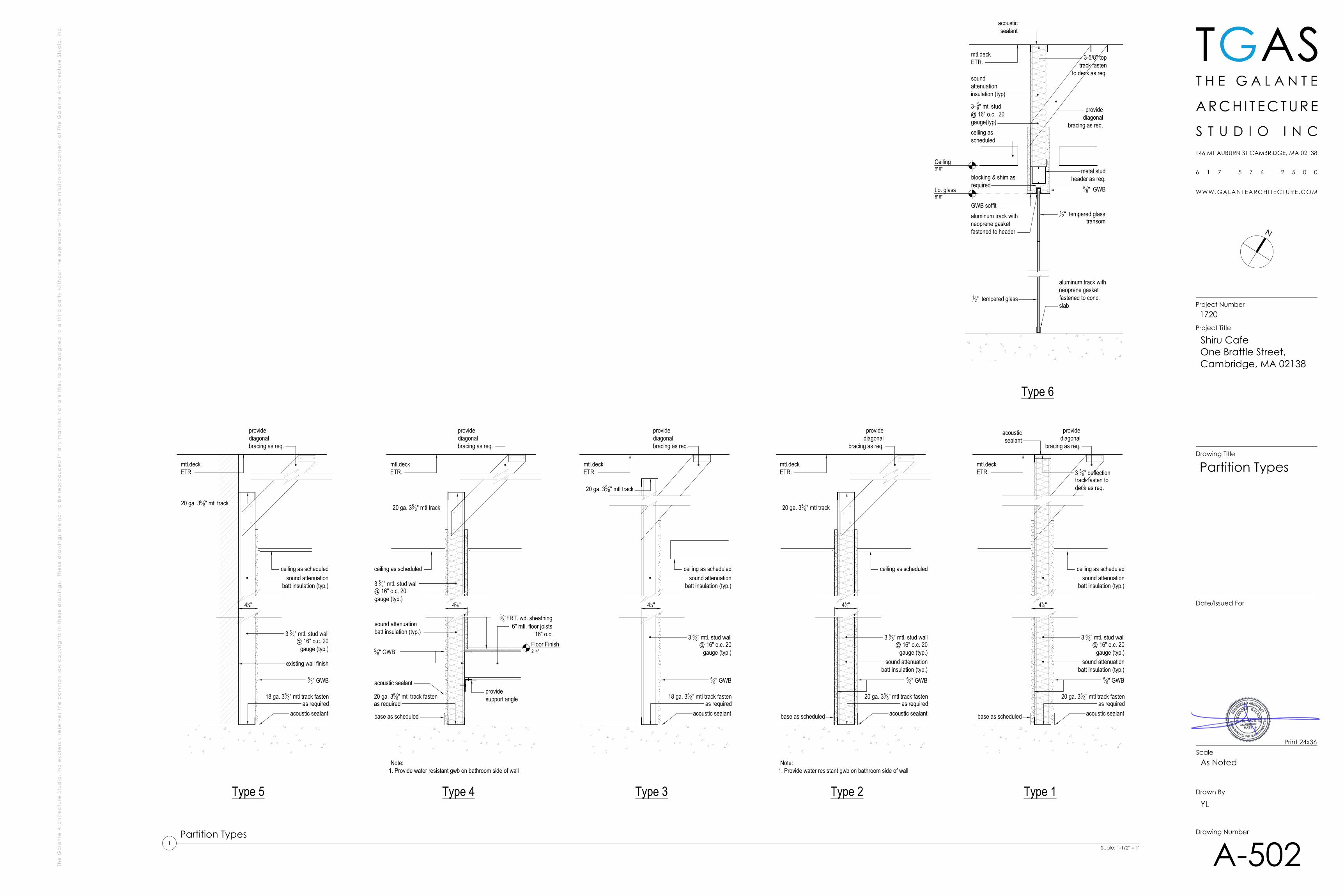
Type 1
20 ga. 358" mtl track fasten
as required
3 5 8" mtl. stud wall@ 16" o.c. 20
gauge (typ.)
58" GWB
acoustic sealant
sound attenuationbatt insulation (typ.)
ceiling as scheduled
3 5 8" deflectiontrack fasten todeck as req.
mtl.deckETR.
base as scheduled
providediagonal
bracing as req.
sound attenuationbatt insulation (typ.)
Type 3Type 5 Type 4 Type 2
414"
18 ga. 358" mtl track fasten
as required
3 5 8" mtl. stud wall@ 16" o.c. 20
gauge (typ.)
58" GWB
acoustic sealant
ceiling as scheduled
mtl.deckETR.
sound attenuationbatt insulation (typ.)
acousticsealant
478"
20 ga. 358" mtl track fasten
as required
3 5 8" mtl. stud wall@ 16" o.c. 20
gauge (typ.)
58" GWB
acoustic sealant
sound attenuationbatt insulation (typ.)
ceiling as scheduled
mtl.deckETR.
base as scheduled
providediagonal
bracing as req.
20 ga. 358" mtl track
Note:1. Provide water resistant gwb on bathroom side of wall
478"
20 ga. 358" mtl track fasten
as required
3 5 8" mtl. stud wall@ 16" o.c. 20gauge (typ.)
58" GWB
acoustic sealant
sound attenuationbatt insulation (typ.)
ceiling as scheduled
mtl.deckETR.
base as scheduled
providediagonalbracing as req.
20 ga. 358" mtl track
Note:1. Provide water resistant gwb on bathroom side of wall
providesupport angle
6" mtl. floor joists16" o.c.
58"FRT. wd. sheathing
414"
18 ga. 358" mtl track fasten
as required
3 5 8" mtl. stud wall@ 16" o.c. 20
gauge (typ.)
acoustic sealant
ceiling as scheduled
mtl.deckETR.
sound attenuationbatt insulation (typ.)
58" GWB
20 ga. 358" mtl track
providediagonalbracing as req.
providediagonalbracing as req.
20 ga. 358" mtl track
existing wall finish
blocking & shim asrequired
GWB soffit 12" tempered glass
transomaluminum track withneoprene gasketfastened to header
5 8" GWB
12" tempered glass
aluminum track withneoprene gasketfastened to conc.slab
Ceiling9' 0"
3-5/8" toptrack fasten
to deck as req.
mtl.deckETR.
t.o. glass8' 6"
3- 58" mtl stud@ 16" o.c. 20gauge(typ)
metal studheader as req.
providediagonal
bracing as req.
soundattenuationinsulation (typ)
acousticsealant
Type 6
ceiling asscheduled
N
TGAS
Scale
Drawn By
Drawing Number
Date/Issued For
Drawing Title
Project Number
Project Title
Shiru CafeOne Brattle Street,Cambridge, MA 02138
1720
As Noted
YL
A-502
Partition Types
Print 24x36
Scale: 1-1/2" = 1'
Partition Types1
ylaakso
Rectangle
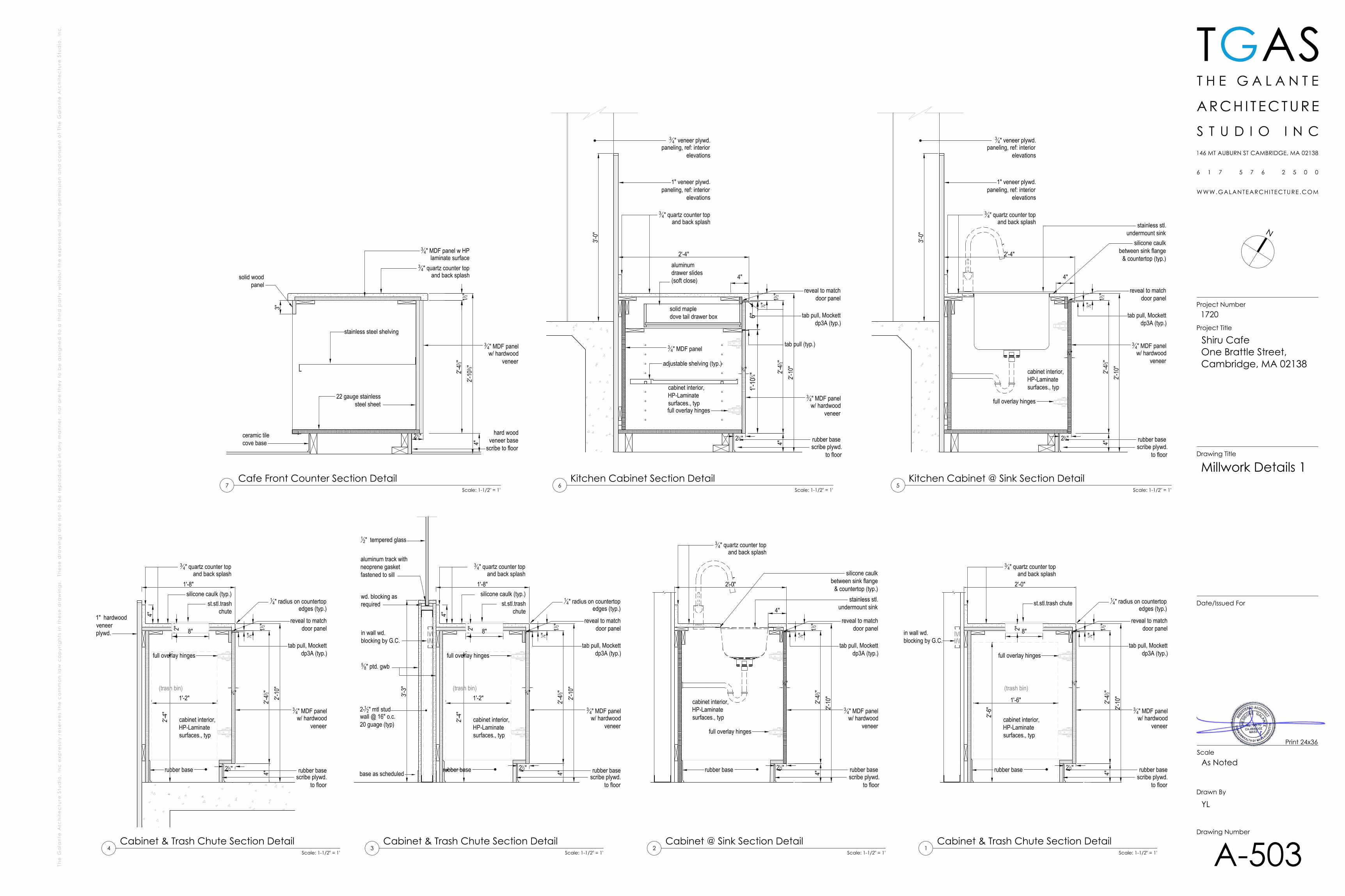
4"2'-
41 2"2'-
10"
1 4"
11 2"
2'-0"
rubber base
full overlay hinges
34" quartz counter top
and back splash
2"
st.stl.trash chute
reveal to matchdoor panel
1'-6"
2'-6"
(trash bin)3
4"
rubber base 212"
cabinet interior,HP-Laminatesurfaces., typ
8"
34" MDF panelw/ hardwood
veneer
tab pull, Mockettdp3A (typ.)
4"2'-
41 2"2'-
10"
1 4"
11 2"
2'-0"
rubber base
full overlay hinges
34" quartz counter top
and back splash
reveal to matchdoor panel
34"
rubber base 212"
cabinet interior,HP-Laminatesurfaces., typ
34" MDF panelw/ hardwood
veneer
tab pull, Mockettdp3A (typ.)
4"stainless stl.
undermount sink
silicone caulkbetween sink flange
& countertop (typ.)
12" tempered glass
wd. blocking as required
base as scheduled
3'-3"
in wall wd.blocking by G.C.
scribe plywd.to floor
scribe plywd.to floor
aluminum track withneoprene gasketfastened to sill
2-12" mtl studwall @ 16" o.c.20 guage (typ)
4"2'-
41 2"2'-
10"
1 4"
11 2"
1'-8"
rubber base
full overlay hinges
34" quartz counter top
and back splash
2"
st.stl.trash chute
reveal to matchdoor panel
1'-2"
2'-4"
(trash bin) 34"
rubber base 212"
cabinet interior,HP-Laminatesurfaces., typ
8"
34" MDF panelw/ hardwood
veneer
tab pull, Mockettdp3A (typ.)
in wall wd.blocking by G.C.
scribe plywd.to floor
14" radius on countertop
edges (typ.)
silicone caulk (typ.)1
4" radius on countertopedges (typ.)
58" ptd. gwb
4"
4"2'-
41 2"2'-
10"
1 4"
11 2"
1'-8"
rubber base
full overlay hinges
34" quartz counter top
and back splash
2"
st.stl.trash chute
reveal to matchdoor panel
1'-2"
2'-4"
(trash bin)3
4"
rubber base 212"
cabinet interior,HP-Laminatesurfaces., typ
8"
34" MDF panelw/ hardwood
veneer
tab pull, Mockettdp3A (typ.)
scribe plywd.to floor
14" radius on countertop
edges (typ.)
silicone caulk (typ.)
4"1" hardwoodveneerplywd.
4"2'-
41 2"2'-
10"
1 4"
11 2"
2'-4"
rubber base
full overlay hinges
34" quartz counter top
and back splash
reveal to matchdoor panel
34"
212"
cabinet interior,HP-Laminatesurfaces., typ
34" MDF panelw/ hardwood
veneer
tab pull, Mockettdp3A (typ.)
4"
stainless stl.undermount sink
silicone caulkbetween sink flange
& countertop (typ.)
scribe plywd.to floor
1" veneer plywd.paneling, ref: interior
elevations
3'-0"
34" veneer plywd.
paneling, ref: interiorelevations
4"2'-
41 2"2'-
10"
1 4"
11 2"
2'-4"
rubber base
full overlay hinges
34" quartz counter top
and back splash
reveal to matchdoor panel
34"
cabinet interior,HP-Laminatesurfaces., typ
34" MDF panelw/ hardwood
veneer
tab pull, Mockettdp3A (typ.)
4"
scribe plywd.to floor
1" veneer plywd.paneling, ref: interior
elevations
3'-0"
34" veneer plywd.
paneling, ref: interiorelevations
34" MDF panel
212"
adjustable shelving (typ.)
1'-10
1 4"6"
tab pull (typ.)
aluminum drawer slides (soft close)
solid mapledove tail drawer box
2'-41 2"
2'-10
3 8"11 2"
ceramic tilecove base
hard wood veneer base
scribe to floor
34" MDF panelw/ hardwood
veneer
34" quartz counter top
and back splash
stainless steel shelving
4"
22 gauge stainlesssteel sheet
212"
34" MDF panel w HP
laminate surface
3"solid wood
panel
N
TGAS
Scale
Drawn By
Drawing Number
Date/Issued For
Drawing Title
Project Number
Project Title
Shiru CafeOne Brattle Street,Cambridge, MA 02138
1720
As Noted
YL
A-503
Millwork Details 1
Print 24x36
Scale: 1-1/2" = 1'
Cabinet & Trash Chute Section Detail1
Scale: 1-1/2" = 1'
Cabinet @ Sink Section Detail2
Scale: 1-1/2" = 1'
Cabinet & Trash Chute Section Detail3
Scale: 1-1/2" = 1'
Cabinet & Trash Chute Section Detail4
Scale: 1-1/2" = 1'
Kitchen Cabinet @ Sink Section Detail5
Scale: 1-1/2" = 1'
Kitchen Cabinet Section Detail6
Scale: 1-1/2" = 1'
Cafe Front Counter Section Detail7
ylaakso
Rectangle
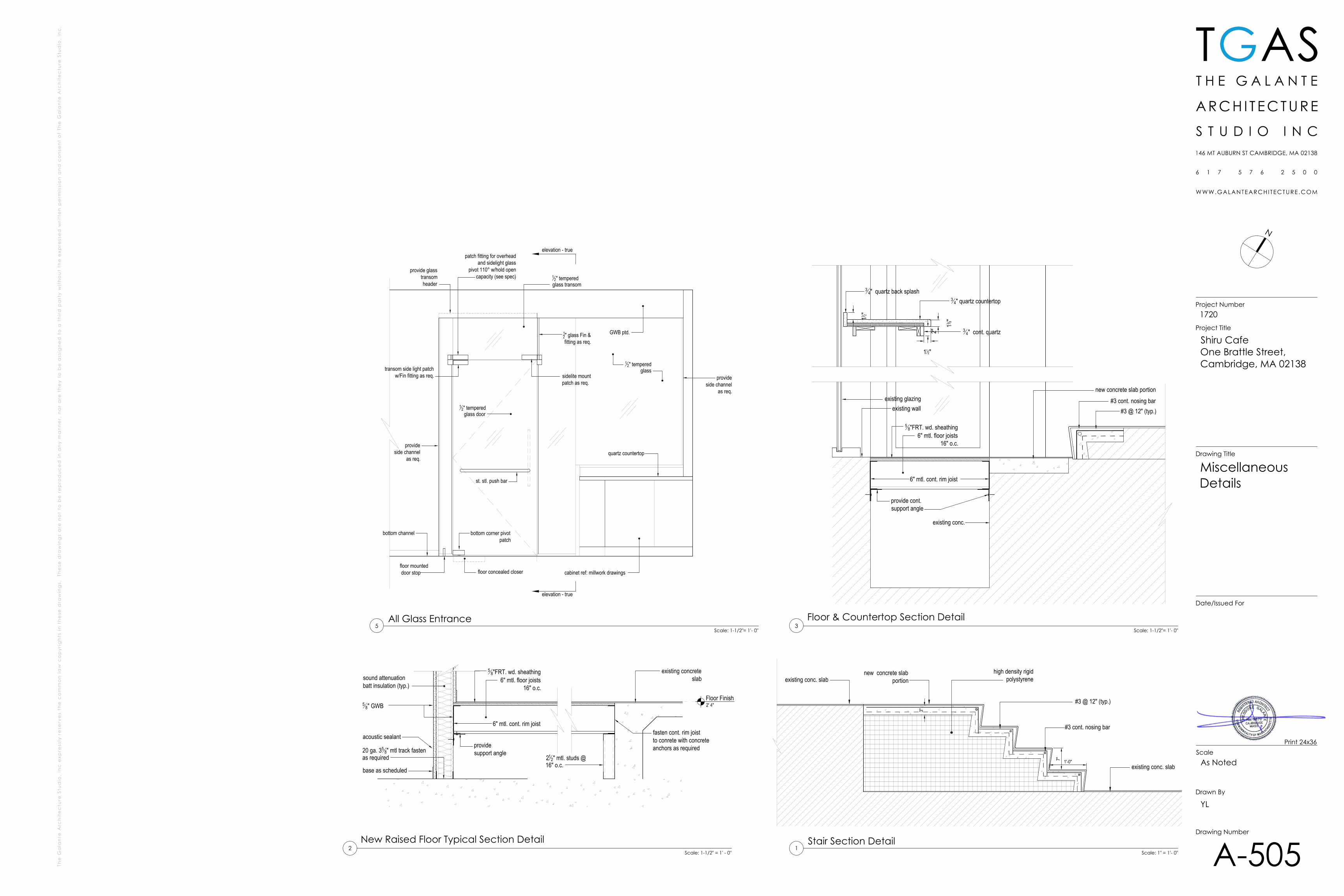
high density rigidpolystyreneexisting conc. slab
existing conc. slab
7" 1'-0"
3"
#3 @ 12" (typ.)
#3 cont. nosing bar
new concrete slabportion
20 ga. 358" mtl track fasten
as required
58" GWB
acoustic sealant
sound attenuationbatt insulation (typ.)
base as scheduled
providesupport angle
6" mtl. floor joists16" o.c.
58"FRT. wd. sheathing
6" mtl. cont. rim joist
existing concreteslab
212" mtl. studs @
16" o.c.
fasten cont. rim joistto conrete with concreteanchors as required
new concrete slab portion
#3 @ 12" (typ.)#3 cont. nosing bar
existing wallexisting glazing
58"FRT. wd. sheathing
6" mtl. floor joists16" o.c.
6" mtl. cont. rim joist
provide cont.support angle
existing conc.
34" quartz countertop
34" cont. quartz
34" quartz back splash
13 8"11 2"
2"
112"
st. stl. push bar
GWB ptd.
12" tempered glass door
12" tempered glass
12" tempered glass transom
bottom corner pivotpatch
floor mounted door stop
transom side light patchw/Fin fitting as req. sidelite mount
patch as req.
bottom channel
provideside channel
as req.
provideside channel
as req.
patch fitting for overhead and sidelight glass
pivot 110° w/hold open capacity (see spec)
cabinet ref: millwork drawings
12" glass Fin & fitting as req.
provide glasstransomheader
floor concealed closer
elevation - true
elevation - true
quartz countertop
N
TGAS
Scale
Drawn By
Drawing Number
Date/Issued For
Drawing Title
Project Number
Project Title
Shiru CafeOne Brattle Street,Cambridge, MA 02138
1720
As Noted
YL
A-505
MiscellaneousDetails
Print 24x36
Scale: 1" = 1'- 0"
Stair Section Detail1
Scale: 1-1/2" = 1' - 0"
New Raised Floor Typical Section Detail2
Scale: 1-1/2"= 1'- 0"
Floor & Countertop Section Detail3
Scale: 1-1/2"= 1'- 0"
All Glass Entrance5
ylaakso
Rectangle
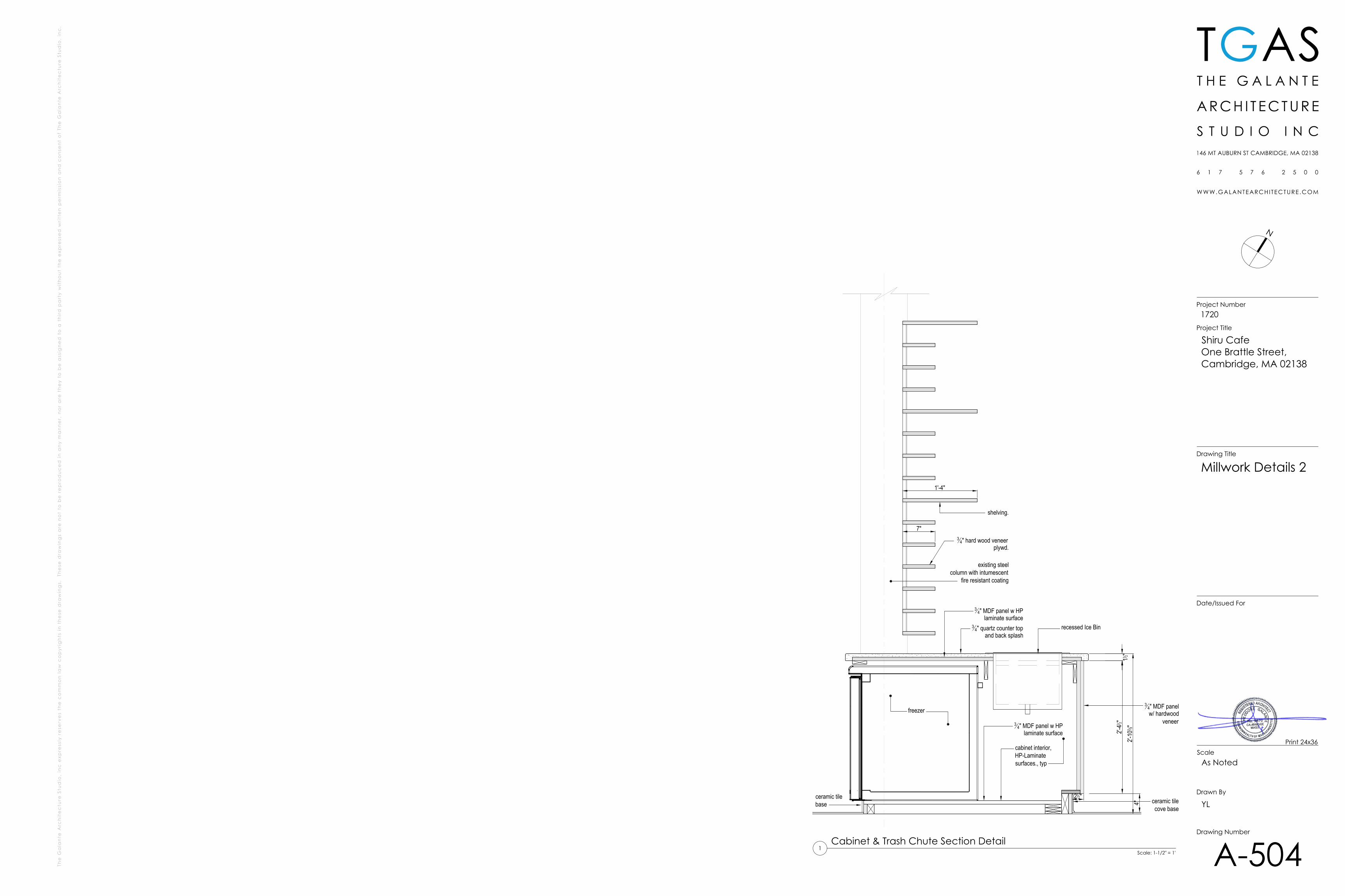
2'-41 2"
2'-10
3 8"11 2"
ceramic tilecove base
34" MDF panelw/ hardwood
veneer
4"
212"
34" quartz counter top
and back splash
34" MDF panel w HP
laminate surfacerecessed Ice Bin
freezer
ceramic tilebase
cabinet interior,HP-Laminatesurfaces., typ
34" MDF panel w HP
laminate surface
34" hard wood veneer
plywd.
1'-4"
7"
shelving.
existing steelcolumn with intumescent
fire resistant coating
N
TGAS
Scale
Drawn By
Drawing Number
Date/Issued For
Drawing Title
Project Number
Project Title
Shiru CafeOne Brattle Street,Cambridge, MA 02138
1720
As Noted
YL
A-504
Millwork Details 2
Print 24x36
Scale: 1-1/2" = 1'
Cabinet & Trash Chute Section Detail1
ylaakso
Rectangle
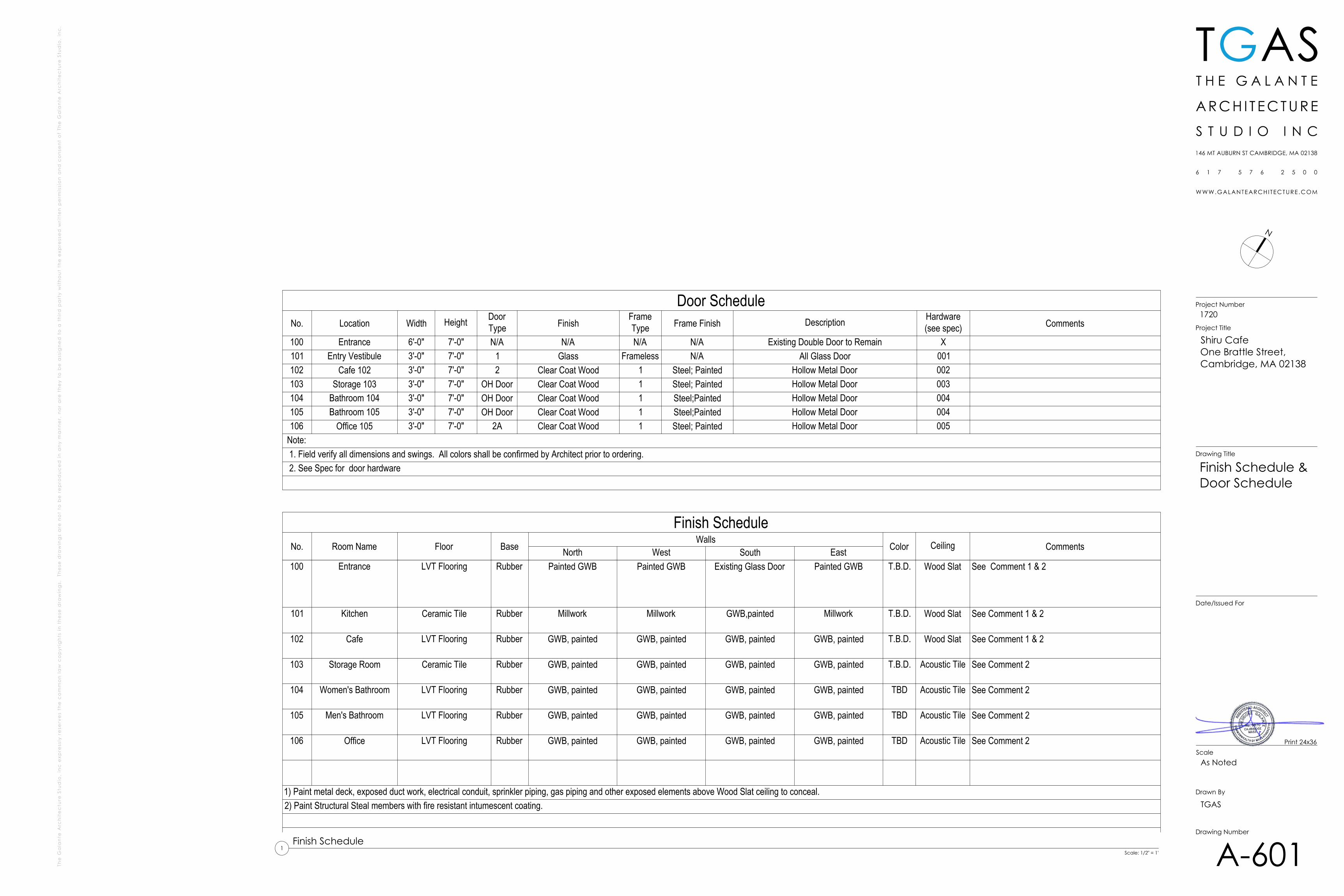
Finish ScheduleNo. Room Name Floor Base
WallsColor Ceiling CommentsNorth West South East
100 Entrance LVT Flooring Rubber Painted GWB Painted GWB Existing Glass Door Painted GWB T.B.D. Wood Slat See Comment 1 & 2
101 Kitchen Ceramic Tile Rubber Millwork Millwork GWB,painted Millwork T.B.D. Wood Slat See Comment 1 & 2
102 Cafe LVT Flooring Rubber GWB, painted GWB, painted GWB, painted GWB, painted T.B.D. Wood Slat See Comment 1 & 2
103 Storage Room Ceramic Tile Rubber GWB, painted GWB, painted GWB, painted GWB, painted T.B.D. Acoustic Tile See Comment 2
104 Women's Bathroom LVT Flooring Rubber GWB, painted GWB, painted GWB, painted GWB, painted TBD Acoustic Tile See Comment 2
105 Men's Bathroom LVT Flooring Rubber GWB, painted GWB, painted GWB, painted GWB, painted TBD Acoustic Tile See Comment 2
106 Office LVT Flooring Rubber GWB, painted GWB, painted GWB, painted GWB, painted TBD Acoustic Tile See Comment 2
1) Paint metal deck, exposed duct work, electrical conduit, sprinkler piping, gas piping and other exposed elements above Wood Slat ceiling to conceal.2) Paint Structural Steal members with fire resistant intumescent coating.
Door ScheduleNo. Location Width Height Door
Type FinishFrameType Frame Finish Description Hardware
(see spec) Comments
100 Entrance 6'-0" 7'-0" N/A N/A N/A N/A Existing Double Door to Remain X101 Entry Vestibule 3'-0" 7'-0" 1 Glass Frameless N/A All Glass Door 001102 Cafe 102 3'-0" 7'-0" 2 Clear Coat Wood 1 Steel; Painted Hollow Metal Door 002103 Storage 103 3'-0" 7'-0" OH Door Clear Coat Wood 1 Steel; Painted Hollow Metal Door 003104 Bathroom 104 3'-0" 7'-0" OH Door Clear Coat Wood 1 Steel;Painted Hollow Metal Door 004105 Bathroom 105 3'-0" 7'-0" OH Door Clear Coat Wood 1 Steel;Painted Hollow Metal Door 004106 Office 105 3'-0" 7'-0" 2A Clear Coat Wood 1 Steel; Painted Hollow Metal Door 005
Note: 1. Field verify all dimensions and swings. All colors shall be confirmed by Architect prior to ordering. 2. See Spec for door hardware
N
TGAS
Scale
Drawn By
Drawing Number
Date/Issued For
Drawing Title
Project Number
Project Title
Shiru CafeOne Brattle Street,Cambridge, MA 02138
1720
As Noted
TGAS
A-601
Finish Schedule &Door Schedule
Print 24x36
Scale: 1/2" = 1'
Finish Schedule1
ylaakso
Rectangle