Testing of HV Cables - Supplementary Information OF HV CABLES – SUPPLEMENTARY INFORMATION Page 1...
24
TESTING OF HV CABLES – SUPPLEMENTARY INFORMATION Page 1 of 24 Reference SP0407R02 Ver 2 Ergon Energy Corporation Limited ABN 50 087 646 062 1. INTRODUCTION This reference is intended to give a basic overview of insulating materials that can be used during high voltage withstand testing, in particular cable testing. The selection and use of an insulating material will depend on a number of factors including: • The test voltages applied to the cables during the test. • Clearance between the phase being tested and the adjacent phases and earthed metalwork. If the installed insulation, including air clearances, provides sufficient dielectric strength then additional insulating material will not be required. • Atmospheric conditions (Insulation provided by air changes with atmospheric changes). • The dielectric properties and dimensions of the insulating material selected. • Does the material need to be tested regularly to check its dielectric strength? The following section of the “Code of Practice – Electrical Work (Electrical Safety Act 2002)” is applicable to the material selected for insulating purposes during cable testing. Section 6.4.2 Selection, testing, maintenance When selecting or maintaining tools, instruments and equipment, you should address a number of factors to ensure electrical safety. At least the following issues are to be addressed: • The device must be fit for purpose; • Equipment and test instruments that can be visually confirmed as functioning correctly should have visual confirmation of correct function each time before use; • Equipment and test instruments that are not able to be visually confirmed as functioning correctly must be tested at least every 6 months to ensure proper working order; • Repairs and maintenance should meet appropriate standards and manufacturer’s instructions. Appropriate guidance and standards for testing, inspecting, calibrating and maintaining these devices can be obtained from sources that include: • Manufactures and suppliers; • Industry groups; • National and international codes and standards such as those produced by: • Standards Australia eg AS and AS/NZS publications; and • International Electrotechnical Commission eg IEC publications.
Transcript of Testing of HV Cables - Supplementary Information OF HV CABLES – SUPPLEMENTARY INFORMATION Page 1...

TESTING OF HV CABLES – SUPPLEMENTARY INFORMATION
Page 1 of 24 Reference SP0407R02 Ver 2
Ergon Energy Corporation Limited ABN 50 087 646 062
1. INTRODUCTION This reference is intended to give a basic overview of insulating materials that can be used during high voltage withstand testing, in particular cable testing. The selection and use of an insulating material will depend on a number of factors including:
• The test voltages applied to the cables during the test. • Clearance between the phase being tested and the adjacent phases and earthed
metalwork. If the installed insulation, including air clearances, provides sufficient dielectric strength then additional insulating material will not be required.
• Atmospheric conditions (Insulation provided by air changes with atmospheric changes). • The dielectric properties and dimensions of the insulating material selected. • Does the material need to be tested regularly to check its dielectric strength?
The following section of the “Code of Practice – Electrical Work (Electrical Safety Act 2002)” is applicable to the material selected for insulating purposes during cable testing. Section 6.4.2 Selection, testing, maintenance When selecting or maintaining tools, instruments and equipment, you should address a number of factors to ensure electrical safety. At least the following issues are to be addressed:
• The device must be fit for purpose; • Equipment and test instruments that can be visually confirmed as functioning correctly should have visual confirmation of
correct function each time before use; • Equipment and test instruments that are not able to be visually confirmed as functioning correctly must be tested at least
every 6 months to ensure proper working order; • Repairs and maintenance should meet appropriate standards and manufacturer’s instructions.
Appropriate guidance and standards for testing, inspecting, calibrating and maintaining these devices can be obtained from sources that include:
• Manufactures and suppliers; • Industry groups; • National and international codes and standards such as those produced by:
• Standards Australia eg AS and AS/NZS publications; and • International Electrotechnical Commission eg IEC publications.

TESTING OF HV CABLES – SUPPLEMENTARY INFORMATION
Page 2 of 24 Reference SP0407R02 Ver 2
Ergon Energy Corporation Limited ABN 50 087 646 062
2. TEST VOLTAGES Standard Work Practice SP0407 “Commissioning Tests for new HV Cables (Up To 33kv)” defines the procedure and test voltages to be used during a cable test. A routine high voltage withstand test shall be carried out on the completed cables. ALL (XLPE and Paper Lead, PILC) cable shall be tested with a VLF alternating voltage whose waveform shall approximate a sinusoidal waveform. The voltage shall be increased gradually and maintained at full value for 30 minutes. The value of test voltage used is specified in the following table for new cables:
Cable designation kV
DC Test Voltage (kV ph to earth)
DC Test Voltage (kV ph to ph)
VLF Test Voltage (kV peak ph to
earth)
50Hz AC Test Voltage (kV RMS ph
to earth)
1.9/3.3 7 10 8 10 3.8/6.6 15 20 16 20 6.35/11 25 34 27 28 12.7/22 50 - 54 50 19/33 75 - 81 70
NOTE: VLF is the preferred method for testing ALL types of cables. In the past DC has been used on Paper Lead (PILC) cables, DC can still be used on PILC cables but only if VLF testing is unavailable.

TESTING OF HV CABLES – SUPPLEMENTARY INFORMATION
Page 3 of 24 Reference SP0407R02 Ver 2
Ergon Energy Corporation Limited ABN 50 087 646 062
Insulation Provided by Air Gaps and Insulating Materials
AIR GAPS Air at normal atmospheric pressure and temperature breaks down at 30kV/cm (peak or crest value) or 21.1kV/cm (r.m.s.). [ASTM D 2477 X1.3]
Material Dielectric Constant
Dielectric Strength
(V/m) Air (atmospheric pressure)
1.0 3 x 10⁶
Mineral Oil 2.3 15 x 106 Paper 2 – 4 15 x 106 Polystyrene 2.6 20 x 106 Rubber 2.3 – 4.0 25 x 106 Glass 4 – 10 30 x 106 Mica 6.0 200 x 106
Dielectric Constants and Dielectric Strengths of some Common Materials [David K. Cheng] IEC Standard reference atmospheric conditions:
Temperature = 20°C (Specified as 25°C in some ASTM standards) Pressure = 101.3 kPa Absolute Humidity = 11g/m3
Relative Humidity = Absolute Humidity / Absolute Humidity in Saturation (Temperature Dependant)
Change in amount of water vapour in saturated air with temperature.
The air's capacity for water vapour increases as the air temperature increases. Air at 30°C can hold more than three times as much water vapour as air at 10°C. An “atmospheric correction factor” needs to be applied to account for the difference between the atmospheric conditions in service and the standard atmospheric conditions. Refer to Appendix B: Standards for Insulation Coordination (Air Gaps) Taking into account a number of correction factors the minimum recommended clearance to grounded objects for AC insulation testing is 10kV AC (r.m.s.) / inch. This figure is based on practical experience and is over 5 times higher than the nominal dielectric strength of air to allow for varying atmospheric conditions, contamination of the insulation, and sharp edges producing high local stresses. 10 kV/inch (r.m.s) = 4 kV/cm (r.m.s) = 0.4 kV/mm (r.m.s) = 0.56 kV/mm (peak)

TESTING OF HV CABLES – SUPPLEMENTARY INFORMATION
Page 4 of 24 Reference SP0407R02 Ver 2
Ergon Energy Corporation Limited ABN 50 087 646 062
Note that minimum clearances may need to be increased for excessive deviations away from the standard atmospheric conditions (eg extremely humid or windy weather). The table above compares the electrical clearances recommended for fixed plant at the voltages used for cable testing against IEC & ASTM minimum clearances for test electrodes and also the 3kV/mm (peak) and 10kV/inch (r.m.s) figures.
Cable designatio
n kV
Test Voltage
KV (Phase-to-Earth)
Standard short- duration
power-frequency withstand voltage
kV (r.m.s. value)
Standard lightning impulse
withstand voltage
kV
(peak value)
Recommended Air Gap Clearances (mm)
AS 1824 AS 2067
AS 2374.3.1
BS 6435 (Phase-to-Earth)
Based on 3kV/mm (peak)
2.11kV/mm
(r.m.s)
Based on 10kV /
inch (AC r.m.s)
Based on IEC test electrode clearanc
es
Based on ASTM
test electrode clearanc
es
DC
(a
vera
ge) 3.3 7 10 40 60 3.3 18.0 80 76
6.6 15 20 60 90 6.7 35.9 80 76 11 25 28 95 160 76 11.3 61.1 150 102 22 50 50 145 280 140 16.7 89.8 260 152 33 75 70 200 380 222 25 134.7 > 305
50H
z A
C
(r.m
.s)
3.3 10 10 40 60 4.7 25.4 80 76 6.6 20 20 60 90 9.5 50.8 80 76 11 28 28 95 160 76 13.3 71.1 150 127 22 50 50 145 280 140 23.7 127.0 300 254 33 70 70 200 380 222 33.2 177.8
VLF
(p
eak)
3.3 8 10 40 60 2.7 14.4 80 76 6.6 16 20 60 90 5.3 28.7 80 76 11 27 28 95 160 76 9.0 48.5 150 102 22 54 50 145 280 140 18.0 97.0 300 152 33 81 70 200 380 222 27.0 145.5 > 305
Note that the fixed plant clearances are for the lightning impulse and short duration power-frequency withstand voltages stated. Refer to section Appendix B: Standards for Insulation Coordination (Air Gaps).

TESTING OF HV CABLES – SUPPLEMENTARY INFORMATION
Page 5 of 24 Reference SP0407R02 Ver 2
Ergon Energy Corporation Limited ABN 50 087 646 062
INSULATING MATERIALS This section provides an overview of various forms of insulating materials.
ELASTOMERS (RUBBERS)
From the range of natural and synthetic “rubbers” which may be classed as elastomers probably only two have the properties suitable for electrical insulation; butyl and ethylene-propylene (EPR). The latter has been well developed for high voltage applications and is used, in extruded form, for some 33kV cables. Common types of rubber insulation include Matting, Sleeves, Blankets, Covers, Line Hoses and Sheeting. These are classified and tested as per Appendix A: Standards relating to insulated mats, covers, etc. The table below shows the required test voltages for various classes of insulating equipment and the recommended voltages AC & DC for each class.
Class of Insulating Equipme
nt
Nominal Maximum Use Voltage, Phase-
Phase ASTM Standards IEC Standards
A.C. r.m.s. V
D.C. V
AC Proof-Test
Voltage rms V
DC Proof-Test
Voltage Average
V
AC Proof-Test
Voltage rms V
DC Proof-Test
Voltage Average V
0 1 000 1 500 5 000 20 000 5 000 10 000 1 7 500 11 250 10 000 40 000 10 000 20 000 2 17 000 25 500 20 000 50 000 20 000 30 000 3 26 500 39 750 30 000 60 000 30 000 40 000 4 36 000 54 000 40 000 70 000 40 000 60 000 Proof test voltages and maximum use voltages for various classes of insulating equipment
Note that Australian Standards for Mats and Covers are for voltages up to 650V only. Refer to Appendix A: Standards relating to insulated mats, covers, etc. Also note that the Ergon Standard Work Practice ST0604 “Insulating Mats and Covers Testing SWP” only caters for low voltage mats and covers rated up to 650V.
PAPERS
A variety of insulating papers are available specifically designed for insulating electrical circuits. Rag and kraft paper often called Transformer Paper is often used to separate windings in transformers or in applications where no sharp edges might poke through the relatively weak paper. Fishpaper is a curious name referring to a grey cotton rag paper usually vulcanized and often laminated with Mylar. The Mylar may have paper on one or both sides and many thickness grades are available. Other "sandwich materials" are available including 100% polyester laminates and are usually a distinct colour. The paper/Mylar laminates resist soldering heat better since the paper doesn't melt and the Dacron/Mylar laminates resist moisture best. Laminates with thicker polyester centres are fashioned into insulating plates in many electro-mechanical devices. A

TESTING OF HV CABLES – SUPPLEMENTARY INFORMATION
Page 6 of 24 Reference SP0407R02 Ver 2
Ergon Energy Corporation Limited ABN 50 087 646 062
typical application may be observed inside most older electrical timers where a printed and folded piece of laminated paper keeps the user's fingers away from the high voltage when adjusting the position of the on and off trippers. Papers made with temperature resistant nylon and/or glass weaves have excellent electrical properties and good temperature resistance. Thin sheets of epoxy-fibreglass usually green in colour are commonly used for insulating PCB's and electronic assemblies with potentially sharp projections. Puncture resistance is superb even for sheets thin enough to be quite flexible. A simple clear polyester sheet is sometimes used for insulation but is offers far less puncture and temperature resistance than the laminates. Kraft paper is 95% to 97% cellulose. When cellulose is subject to normal atmospheric conditions, it could contain water to approximately 8% of its own weight depending on the humidity and temperature of the surrounding atmosphere. Cellulose material such as paper, pressboard and wood, commonly used as insulation and supports in power transformers, is very hygroscopic. In fact, paper is just one third as effective as a desiccant, as silica gel. Water in such a material reduces the insulation strength, increases loss angle, and adversely affects the ageing characteristics. As the water content increases, paper swells, and conversely shrinks as it is dried. Typical Dielectric Strengths: Rag Paper – 300V/mil (11.8kV/mm) Kraft Paper – 250V/mil (9.8kV/mm) Fish Paper – 200 to 400V/mil (7.9 to 15.8kV/mm) * These values will vary depending on manufacturing process, atmospheric conditions, etc. NOMEX: NOMEX® is a Dupont aromatic polyamide with an operating temperature range over 220 degrees centigrade and with superb high voltage breakdown. It is an excellent choice for standardisation since it outperforms many other materials. In densified form, NOMEX® products withstand short-term electrical stresses of 18 to 40 kV/mm depending on product type and thickness, with no need for further treatment with varnishes or resins. In equilibrium at 95 percent relative humidity, densified NOMEX® papers and pressboards maintain 90 percent of their bone-dry dielectric strength while many mechanical properties are actually improved.
TAPES
Tapes are made from many materials. Vinyl tapes are commonly used for wire insulation and are available in all the colours necessary for colour coding. Mylar tapes are common in electronics: film capacitors often have a final wrap of yellow Mylar tape. Acetate tapes are used where good conformability is desired as when covering coils as is white cotton cloth tape. Glass cloth electrical tape with thermosetting adhesive (adhesive that permanently sets with temperature) is used to secure and protect heater windings or insulate components exposed to heat. Kapton, Teflon, and other insulators are used to make high performance specialty tapes for harsh temperature or chemical environment. KAPTON: Polyimide film has exceptionally good heat resistance and superb mechanical and electrical properties. Kapton tapes are fairly expensive but often indispensable. (Typical Dielectric Strength 80 to 165kV/mm). POLYESTER (MYLAR): A strong material often used in film sheets and tapes for graphic arts and electronics. Those shiny balloons and "space blankets" are usually made from metallised Mylar. Mylar is also used as a dielectric in capacitors. PVC: Polyvinylcloride or PVC is perhaps the most common insulating material. Most wiring is insulated with PVC including house wiring. Irradiated PVC has superior strength and resistance to heat. PVC tapes and tubing are also quite common. Electrical and electronic housings are commonly moulded from PVC.

TESTING OF HV CABLES – SUPPLEMENTARY INFORMATION
Page 7 of 24 Reference SP0407R02 Ver 2
Ergon Energy Corporation Limited ABN 50 087 646 062
TFE (TEFLON): Teflon is an excellent high temperature insulation with superb electrical properties. Teflon tubing and wire insulation comes in a variety of colours and typically feels slippery. The insulation is impervious to the heat and chemicals normally encountered in electronics manufacturing but the material will "cold flow" so Teflon insulation is avoided where sharp corners or points are encountered. Laminated TFE circuit boards take advantage of Teflon's excellent microwave characteristics. Teflon emits a dangerous gas when exposed to extreme heat. White Teflon terminals are commonly used where extremely good insulation is required. The slick surface repels water so the insulation properties are fantastic even in high humidity. High quality I.C. sockets are made from Teflon to reduce leakage currents. Teflon and Teflon composite tapes with adhesive are available. FEP is a lower temperature Teflon. Dielectric strength of some common types of electrical tape:
Voltage Rating
Dielectric Strength (Thickness)
Dielectric Breakdown Test Standard
3M™ Vinyl Electrical Tape Highland Vinyl Electrical Tape 600V 1200V/mil (47.2kV/mm) Scotch 22 Heavy Duty Vinyl Electrical Tape 600V 12,000V ASTM D 1000 Scotch 33 Vinyl Electrical Tape 1000V/mil (39.4kV/mm) ASTM D 1000 Scotch 35 Vinyl Electrical Colour Coding Tape 600V 1250V/mil (49.2kV/mm) ASTM D 1000 Scotch 66R Vinyl Electrical Tape 600V 10,000V ASTM D 1000 Scotch Super 33 Plus Vinyl Electrical Tape 600V 1150V/mil (45.2kV/mm) ASTM D 1000 Super 88 Vinyl Electrical Tape 600V 10,000V ASTM D 1000 Temflex 1700 Vinyl Electrical Tape 600V 1000V/mil (39.4kV/mm) ASTM D 1000 3M™ Insulating and Splicing Tape 2155 Rubber Splicing Tape 600V 600V/mil (23.6kV/mm) 77 Fire Retardant Elec. Arc Proofing 700V/mil (27.6kV/mm) ASTM D 1000 Scotch 130C Linerless Rubber Splicing Tape 69kV 750V/mil (29.5kV/mm) ASTM D 4325 Scotch 2242 Linerless Electrical Rubber Tape 750V/mil (29.5kV/mm) ASTM D 4325 Scotch 23 All-Voltage Splicing Tape 69kV 850V/mil (33.5kV/mm) ASTM D 4325 Scotch 2510 and 2520 Varnished Cambric Tape 800V/mil (31.5kV/mm) ASTM D 295 Scotch 70 Self-Fusing Silicone Rubber Electrical Tape 875V/mil (34.5kV/mm) ASTM D 1000 Scotchfil Electrical Insulation Putty 600V 575V/mil (22.6kV/mm) 3M™ Sealing and Insulating Tape Scotch 2200, 2210 Vinyl Mastic Pads & Rolls 600V 300V/mil (11.8kV/mm) ASTM D 1000 Scotch 2228 Rubber Mastic Tape 500V/mil (19.7kV/mm) ASTM D 4325 Scotch-Seal 2229 Mastic Tape and Pads 379V/mil (14.9kV/mm) ASTM D 1000 3M™ Special Use Tapes 27 Glass Cloth Electrical Tape 600V 3,000V ASTM D 1000 Scotch 69 Glass Cloth Tape 600V 3,500V ASTM D 1000 Plymouth Bishop Vinyl Plastic Tapes Heavy Duty 2 600V 10,000V ASTM-D-1000 Revere ® 7 600V 7,000V ASTM-D-1000 Premium 37 600V 7,000V ASTM-D-1000 Premium 85 CW 600V 11,000V ASTM-D-1000 Premium 111 600V 10,000V ASTM-D-1000 Columbia 600V 1100V/mil (43.3kV/mm) ASTM-D-1000 Plymouth Bishop Low Voltage Tapes 125 Electrical Filler Tape 5kV 585V/mil (23kV/mm) ASTM-D-4325 150 ASTM Rubber Tape 2kV 350V/mil (13.8kV/mm) ASTM-D-4325 122 Rubber Tape 600V 350V/mil (13.8kV/mm) UL510 10 Plyseal ® Insulating Mastic 600V 500V/mil (19.7kV/mm) ASTM-D-4325 4000 Plyseal ® -V Insulating Mastic 1000V 500V/mil (19.7kV/mm) ASTM-D-4325

TESTING OF HV CABLES – SUPPLEMENTARY INFORMATION
Page 8 of 24 Reference SP0407R02 Ver 2
Ergon Energy Corporation Limited ABN 50 087 646 062
Voltage Rating
Dielectric Strength (Thickness)
Dielectric Breakdown Test Standard
5000 Bus-Seal ® Insulating Mastic (EPR-Backed) 500V/mil (19.7kV/mm) ASTM-D-4325 Rubber Mastic (RM) Tape 400V/mil (15.8kV/mm) ASTM-D-4325 Vinyl Mastic (VM) Tape 600V 500V/mil (19.7kV/mm) ASTM-D-4325 Plymouth Bishop High Voltage Tapes W962 EPR High Voltage Tape 138kV 950V/mil (37.4kV/mm) ASTM-D-4325 W963 Plysafe ® EPR High Voltage Tape 69kV 750V/mil (29.5kV/mm) ASTM-D-4325 L969 Plyvolt ® Linerless EPR High Voltage Tape 69kV 780V/mil (30.7kV/mm) ASTM-D-4325 3 Bi-Seal ® 20 Polyethylene & EPR High Voltage Tape 69kV 900V/mil (35.4kV/mm) ASTM-D-4325 3 Bi-Seal ® 30 Polyethylene & EPR High Voltage Tape 69kV 900V/mil (35.4kV/mm) ASTM-D-4325 20 Plysil ® Silicone Rubber Tape 69kV 600V/mil (23.6kV/mm) ASTM-D-2148 Plymouth ® PIB Medium Voltage Tape 46kV 900V/mil (35.4kV/mm) ASTM-D-4325 Plymouth Bishop Mining Products L969 Plyvolt ® Linerless EPR High Voltage Tape 69kV 780V/mil (30.7kV/mm) ASTM-D-4325 Plymouth Bishop Special Tapes 77 Plyglas ® Glass Cloth Tape 600V 2,500V ASTM-D-1000 60 and 60A Varnished Cambric Tape 1000V/mil (39.4kV/mm) ASTM-D-295
HEAT SHRINKABLE MATERIALS
An important development was the introduction of heat shrinkable polymeric materials. This led to changes in the techniques adopted for 11kV (and above) cable terminations. Much testing has been completed in the laboratory and at outdoor test sites. Assessment included the determination of the behaviour of the shrunken material when subjected to thermal cycling, as in a cable. Air gaps must not appear between the sleeve and the cable insulation (plastic or impregnated), as this could result in partial discharges with subsequent failure.

TESTING OF HV CABLES – SUPPLEMENTARY INFORMATION
Page 9 of 24 Reference SP0407R02 Ver 2
Ergon Energy Corporation Limited ABN 50 087 646 062
Dielectric strength of some common heat shrink products:
Dielectric Strength (Thickness) Standard
3M™ Heat Shrink EPS-200 Tubing 800V/mil (31.5kV/mm) MIL-DTL-23053/4, Class 2 EPS-300 Tubing 700V/mil (27.6kV/mm) MIL-I-23053/4, Class 3 EPS-400 Tubing 700V/mil (27.6kV/mm) MIL-I-23053/4. FP-301 Tubing 900V/mil (35.4kV/mm) MIL-I-23053/5, Class 1 and 2 HDT Tubing 500V/mil (19.7kV/mm) MIL-I-23053/15, Class 1 IMCSN Medium Wall Tubing 500V/mil (19.7kV/mm) MIL-I-23053/15, Class 2 ITCSN Heavy Wall Tubing 500V/mil (19.7kV/mm) UL 486D MW Tubing 900V/mil (35.4kV/mm) MIL-I-23053/4, Class 1 SFTW-202 GYS Tubing 700V/mil (27.6kV/mm) MIL-DTL-23053/5, Class 1 SFTW-203 Tubing 700V/mil (27.6kV/mm) MIL-DTL-23053/5, Class 1 SMS Heat Shrink Tubing 500V/mil (19.7kV/mm) SR-350 Tubing 800V/mil (31.5kV/mm) MIL-DTL-23053/6, Class 1, 2 TES Tubing 500V/mil (19.7kV/mm) TMW Tubing 900V/mil (35.4kV/mm) TP Tubing 800V/mil (31.5kV/mm) VFP-876 Tubing 800V/mil (31.5kV/mm) MIL-R-46846, Type V MDT Medium Wall Tubing 500V/mil (19.7kV/mm) MIL-I-23053/15, Class 1 KYNAR Thin Wall Tubing 900V/mil (35.4kV/mm) MIL-DTL-23053/18, Class 1; MIL-DTL-23053/8 Raychem Heat Shrink ZCSM Heat-shrinkable heavy-wall tubing 305V/mil (12kV/mm) IEC 60243 WCSM Heat-shrinkable heavy-wall insulating tubing 305V/mil (12kV/mm) IEC 60243 MWTM Heat-shrinkable medium wall insulating tubing 508V/mil (20kV/mm) IEC 60243 CABAC Heat Shrink XDW - Heatshrink - Dual - Walled Flexible Glue Lined 508V/mil (20kV/mm) MIL-1-23053/4 XLP - Heatshrink - Thin Wall - Flame Retarded 635V/mil (25kV/mm) MIL-1-23053/5 Class 3 SMDW – Medium Walled Heatshrink 457V/mil (18kV/mm) SRE - Heatshrink - End Caps 254V/mil (10kV/mm) HST20 heatshrink tape 762V/mil (30kV/mm)
1 Mil = 0.0254 millimeters
TESTING OF HV CABLES – SUPPLEMENTARY INFORMATION
Page 10 of 24 Reference SP0407R02 Ver 2
Ergon Energy Corporation Limited ABN 50 087 646 062
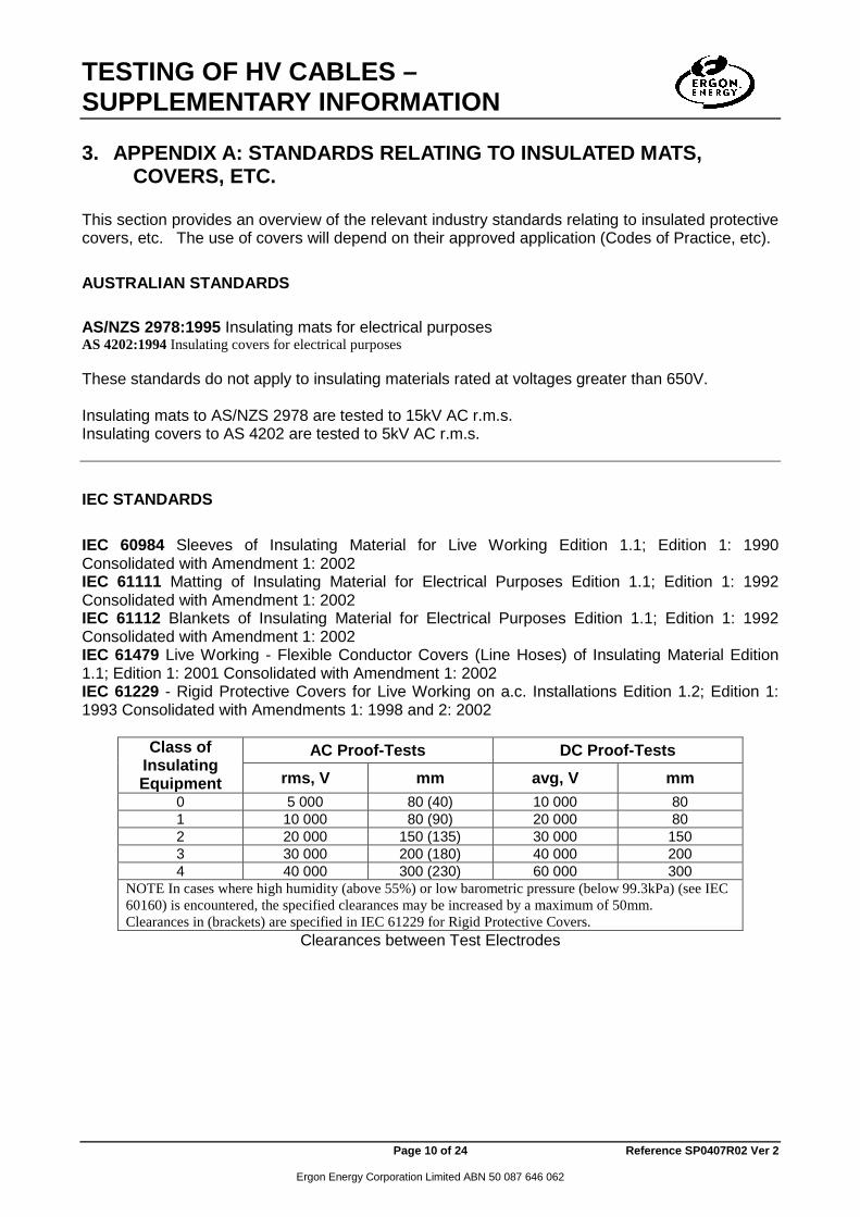
3. APPENDIX A: STANDARDS RELATING TO INSULATED MATS, COVERS, ETC.
This section provides an overview of the relevant industry standards relating to insulated protective covers, etc. The use of covers will depend on their approved application (Codes of Practice, etc).
AUSTRALIAN STANDARDS AS/NZS 2978:1995 Insulating mats for electrical purposes AS 4202:1994 Insulating covers for electrical purposes These standards do not apply to insulating materials rated at voltages greater than 650V. Insulating mats to AS/NZS 2978 are tested to 15kV AC r.m.s. Insulating covers to AS 4202 are tested to 5kV AC r.m.s.
IEC STANDARDS IEC 60984 Sleeves of Insulating Material for Live Working Edition 1.1; Edition 1: 1990 Consolidated with Amendment 1: 2002 IEC 61111 Matting of Insulating Material for Electrical Purposes Edition 1.1; Edition 1: 1992 Consolidated with Amendment 1: 2002 IEC 61112 Blankets of Insulating Material for Electrical Purposes Edition 1.1; Edition 1: 1992 Consolidated with Amendment 1: 2002 IEC 61479 Live Working - Flexible Conductor Covers (Line Hoses) of Insulating Material Edition 1.1; Edition 1: 2001 Consolidated with Amendment 1: 2002 IEC 61229 - Rigid Protective Covers for Live Working on a.c. Installations Edition 1.2; Edition 1: 1993 Consolidated with Amendments 1: 1998 and 2: 2002
Class of Insulating Equipment
AC Proof-Tests DC Proof-Tests rms, V mm avg, V mm
0 5 000 80 (40) 10 000 80 1 10 000 80 (90) 20 000 80 2 20 000 150 (135) 30 000 150 3 30 000 200 (180) 40 000 200 4 40 000 300 (230) 60 000 300
NOTE In cases where high humidity (above 55%) or low barometric pressure (below 99.3kPa) (see IEC 60160) is encountered, the specified clearances may be increased by a maximum of 50mm. Clearances in (brackets) are specified in IEC 61229 for Rigid Protective Covers.
Clearances between Test Electrodes
TESTING OF HV CABLES – SUPPLEMENTARY INFORMATION
Page 11 of 24 Reference SP0407R02 Ver 2
Ergon Energy Corporation Limited ABN 50 087 646 062
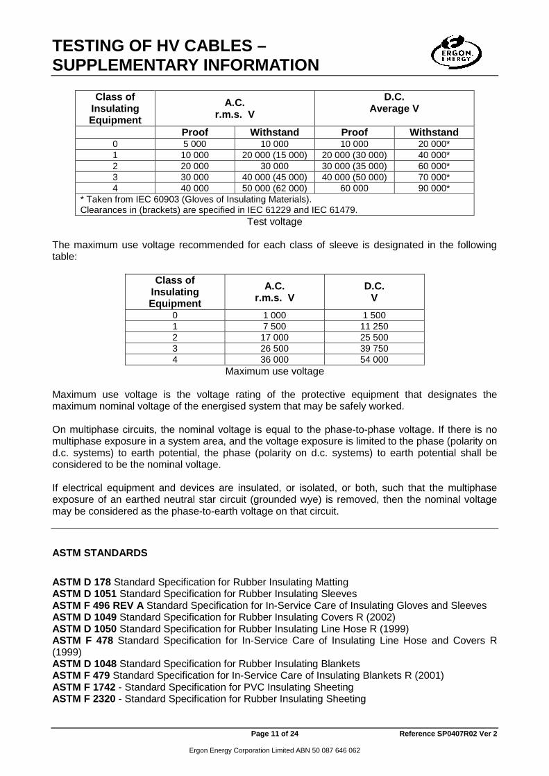
Class of
Insulating Equipment
A.C. r.m.s. V
D.C. Average V
Proof Withstand Proof Withstand 0 5 000 10 000 10 000 20 000* 1 10 000 20 000 (15 000) 20 000 (30 000) 40 000* 2 20 000 30 000 30 000 (35 000) 60 000* 3 30 000 40 000 (45 000) 40 000 (50 000) 70 000* 4 40 000 50 000 (62 000) 60 000 90 000*
* Taken from IEC 60903 (Gloves of Insulating Materials). Clearances in (brackets) are specified in IEC 61229 and IEC 61479.
Test voltage The maximum use voltage recommended for each class of sleeve is designated in the following table:
Class of Insulating Equipment
A.C. r.m.s. V
D.C. V
0 1 000 1 500 1 7 500 11 250 2 17 000 25 500 3 26 500 39 750 4 36 000 54 000
Maximum use voltage Maximum use voltage is the voltage rating of the protective equipment that designates the maximum nominal voltage of the energised system that may be safely worked. On multiphase circuits, the nominal voltage is equal to the phase-to-phase voltage. If there is no multiphase exposure in a system area, and the voltage exposure is limited to the phase (polarity on d.c. systems) to earth potential, the phase (polarity on d.c. systems) to earth potential shall be considered to be the nominal voltage. If electrical equipment and devices are insulated, or isolated, or both, such that the multiphase exposure of an earthed neutral star circuit (grounded wye) is removed, then the nominal voltage may be considered as the phase-to-earth voltage on that circuit.
ASTM STANDARDS ASTM D 178 Standard Specification for Rubber Insulating Matting ASTM D 1051 Standard Specification for Rubber Insulating Sleeves ASTM F 496 REV A Standard Specification for In-Service Care of Insulating Gloves and Sleeves ASTM D 1049 Standard Specification for Rubber Insulating Covers R (2002) ASTM D 1050 Standard Specification for Rubber Insulating Line Hose R (1999) ASTM F 478 Standard Specification for In-Service Care of Insulating Line Hose and Covers R (1999) ASTM D 1048 Standard Specification for Rubber Insulating Blankets ASTM F 479 Standard Specification for In-Service Care of Insulating Blankets R (2001) ASTM F 1742 - Standard Specification for PVC Insulating Sheeting ASTM F 2320 - Standard Specification for Rubber Insulating Sheeting

TESTING OF HV CABLES – SUPPLEMENTARY INFORMATION
Page 12 of 24 Reference SP0407R02 Ver 2
Ergon Energy Corporation Limited ABN 50 087 646 062
ASTM F 968 Standard Specification for Electrically Insulating Plastic Guard Equipment for Protection of Workers R (2002) ASTM F 712 Standard Test Methods for Electrically Insulating Plastic Guard Equipment for Protection of Workers R (2000)
Class of Insulating Equipment
Nominal Maximum Use VoltageA,
Phase-Phase ac, rms
AC Proof-Test Voltage rms V
DC Proof-Test Voltage
Average V 0 1 000 5 000 20 000 1 7 500 10 000 40 000 2 17 000 20 000 50 000 3 26 500 30 000 60 000 4 36 000 40 000 70 000
Proof-Test/Use Voltage Relationship The ac voltage (rms) classification of the protective equipment designates the maximum nominal design voltage of the energised system that may be safely worked. The nominal design voltage is equal to: 1. The phase to phase on multiphase circuits or 2. The phase to ground voltage on single phase grounded circuits. AExcept for Class 0 equipment, the maximum use voltage is based on the following formula: Maximum use voltage (maximum nominal design voltage) = 0.95 ac proof-test voltage – 2000 V
Class of Insulating Equipment
AC Proof-Test DC Proof-Test rms, V mm avg, V mm
0 5 000 76 20 000 76 1 10 000 76 40 000 102 (76) 2 20 000 127 50 000 152 3 30 000 178 60 000 203 4 40 000 254 (178) 70 000 305 (254)
Clearances in (brackets) are specified in other ASTM standards. Clearances between Test ElectrodesABC
AClearance is the shortest electrical path from electrode to electrode around the open edge of the equipment. Permissible tolerance equals ± 25mm. BThese nominal clearances are intended to avoid flashover and may be increased by no more than 51mm when required by a change in atmospheric conditions from the standard of 100kPa (1 atm) barometric pressure and average humidity conditions. These clearances may be decreased if atmospheric conditions permit. CDC proof –test voltages were determined using negative polarity.

TESTING OF HV CABLES – SUPPLEMENTARY INFORMATION
Page 13 of 24 Reference SP0407R02 Ver 2
Ergon Energy Corporation Limited ABN 50 087 646 062
4. APPENDIX B: STANDARDS FOR INSULATION COORDINATION (AIR GAPS)
IEEE 1313.1 - Standard for Insulation Coordination - Definitions, Principles, and Rules IEEE 1313.2 - Guide for the Application of Insulation Coordination IEC 60071-1 Insulation Co-Ordination Part 1: Definitions, Principles and Rules Seventh Edition; Cancels and Replaces IEC 71-3: 1982 IEC 60071-2 Insulation co-ordination - Part 2: Application guide Third Edition (not in Ergon subscription) AS 1824.1—1995 (IEC 71-1:1993) Insulation co-ordination Part 1: Definitions, principles and rules For phase-to-phase insulation, range I, the standard short-duration power-frequency and lightning impulse phase-to-phase withstand voltages are equal to the relevant phase-to-earth withstand voltages (table 2). The values in brackets, however, may be insufficient to prove that the required withstand voltages are met and additional phase-to-phase withstand tests may be needed.
TABLE ZZ2 STANDARD INSULATION LEVELS FOR RANGE 1
(1 kV < Um ≤ 245 kV)
Highest voltage for equipment
Um KV
(r.m.s. value)
Standard short- duration power-
frequency withstand voltage
kV (r.m.s. value)
Standard lightning impulse withstand
voltage kV
(peak value)
3.6 10 20 40
7.2 20 40 60
12 28 60 75 95
17.5 38 75 95
24 50 95 125 145
36 70 145 170 200
52 95 250 72.5 140 325 123 (185) 450
230 550 145 (185) (450)
230 550 275 650
170 (230) (550) 275 650 325 750
245 (275) (650) (325) (750) 360 850 395 950 460 1050
NOTES:
TESTING OF HV CABLES – SUPPLEMENTARY INFORMATION
Page 14 of 24 Reference SP0407R02 Ver 2
Ergon Energy Corporation Limited ABN 50 087 646 062
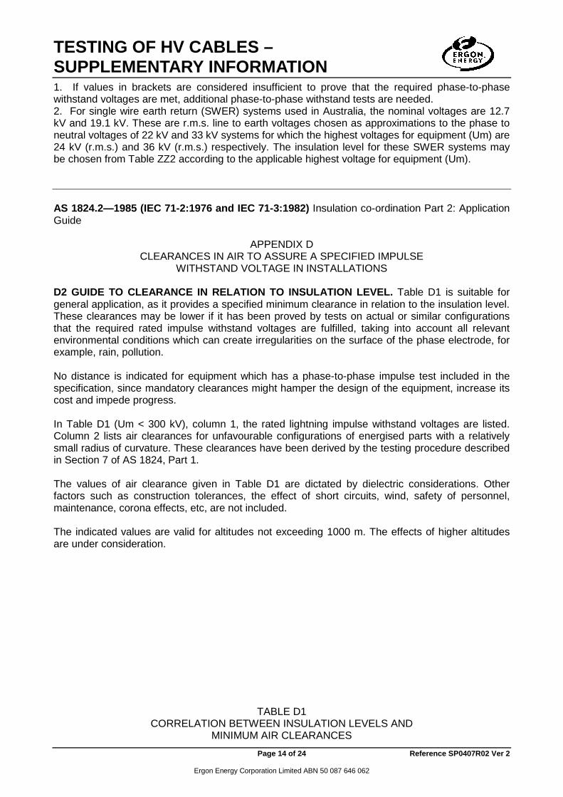
1. If values in brackets are considered insufficient to prove that the required phase-to-phase withstand voltages are met, additional phase-to-phase withstand tests are needed. 2. For single wire earth return (SWER) systems used in Australia, the nominal voltages are 12.7 kV and 19.1 kV. These are r.m.s. line to earth voltages chosen as approximations to the phase to neutral voltages of 22 kV and 33 kV systems for which the highest voltages for equipment (Um) are 24 kV (r.m.s.) and 36 kV (r.m.s.) respectively. The insulation level for these SWER systems may be chosen from Table ZZ2 according to the applicable highest voltage for equipment (Um). AS 1824.2—1985 (IEC 71-2:1976 and IEC 71-3:1982) Insulation co-ordination Part 2: Application Guide
APPENDIX D CLEARANCES IN AIR TO ASSURE A SPECIFIED IMPULSE
WITHSTAND VOLTAGE IN INSTALLATIONS D2 GUIDE TO CLEARANCE IN RELATION TO INSULATION LEVEL. Table D1 is suitable for general application, as it provides a specified minimum clearance in relation to the insulation level. These clearances may be lower if it has been proved by tests on actual or similar configurations that the required rated impulse withstand voltages are fulfilled, taking into account all relevant environmental conditions which can create irregularities on the surface of the phase electrode, for example, rain, pollution. No distance is indicated for equipment which has a phase-to-phase impulse test included in the specification, since mandatory clearances might hamper the design of the equipment, increase its cost and impede progress. In Table D1 (Um < 300 kV), column 1, the rated lightning impulse withstand voltages are listed. Column 2 lists air clearances for unfavourable configurations of energised parts with a relatively small radius of curvature. These clearances have been derived by the testing procedure described in Section 7 of AS 1824, Part 1. The values of air clearance given in Table D1 are dictated by dielectric considerations. Other factors such as construction tolerances, the effect of short circuits, wind, safety of personnel, maintenance, corona effects, etc, are not included. The indicated values are valid for altitudes not exceeding 1000 m. The effects of higher altitudes are under consideration.
TABLE D1 CORRELATION BETWEEN INSULATION LEVELS AND
MINIMUM AIR CLEARANCES

TESTING OF HV CABLES – SUPPLEMENTARY INFORMATION
Page 15 of 24 Reference SP0407R02 Ver 2
Ergon Energy Corporation Limited ABN 50 087 646 062
Um < 300 kV
1 2 Rated lightning impulse
withstand voltage kV
Minimum phase-to-earth and phase-to-phase air
clearances mm
40 60 60 90 75 120 95 160 125 220 150 280 170 320 200 380 325 630 450 900 550 1100 650 1300 750 1500 850 1700 950 1900 1050 2100
AS 2067:1984 Switchgear assemblies and ancillary equipment for alternating voltages above 1 kV.
TESTING OF HV CABLES – SUPPLEMENTARY INFORMATION
Page 16 of 24 Reference SP0407R02 Ver 2
Ergon Energy Corporation Limited ABN 50 087 646 062
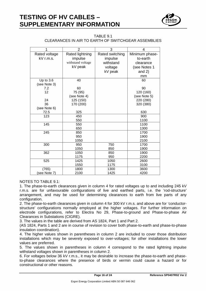
TABLE 9.1
CLEARANCES IN AIR TO EARTH OF SWITCHGEAR ASSEMBLIES
1 2 3 4 Rated voltage
kV r.m.s. Rated lightning
impulse withstand voltage
kV peak
Rated switching impulse
withstand voltage kV peak
Minimum phase-to-earth
clearance (see Notes 1
and 2) mm
Up to 3.6 40 60 (see Note 3)
7.2 60 90 12 75 (95) 120 (160)
(see Note 4) (see Note 5) 24 125 (150) 220 (280) 36 170 (200) 320 (380)
(see Note 6) 72.5 325 630 123 450 900
550 1100 145 550 1100
650 1300 245 850 1700
950 1900 1050 2100
300 950 750 1700 1050 850 1900
362 1050 850 1900 1175 950 2200
525 1425 1050 2600 1550 1175 3100
(765) 1800 1300 3600 (see Note 7) 2100 1425 4200
NOTES TO TABLE 9.1: 1. The phase-to-earth clearances given in column 4 for rated voltages up to and including 245 kV r.m.s. are for unfavourable configurations of live and earthed parts, i.e. the ‘rod-structure’ arrangement, and may be used for determining clearances to earth from live parts of any configuration. 2. The phase-to-earth clearances given in column 4 for 300 kV r.m.s. and above are for ‘conductor-structure’ configurations normally employed at the higher voltages. For further information on electrode configurations, refer to Electra No 29, Phase-to-ground and Phase-to-phase Air Clearances in Substations (CIGRE). 3. The values in the table are derived from AS 1824, Part 1 and Part 2. (AS 1824, Parts 1 and 2 are in course of revision to cover both phase-to-earth and phase-to-phase insulation coordination). 4. The higher values shown in parentheses in column 2 are included to cover those distribution installations which may be severely exposed to over-voltages; for other installations the lower values are preferred. 5. The values shown in parentheses in column 4 correspond to the rated lightning impulse withstand voltages shown in parentheses in column 2. 6. For voltages below 36 kV r.m.s., it may be desirable to increase the phase-to-earth and phase-to-phase clearances where the presence of birds or vermin could cause a hazard or for constructional or other reasons.

TESTING OF HV CABLES – SUPPLEMENTARY INFORMATION
Page 17 of 24 Reference SP0407R02 Ver 2
Ergon Energy Corporation Limited ABN 50 087 646 062
7. The value shown in parentheses in column 1 is not an Australian standard voltage and is included only to designate additional impulse withstand voltages available. 9.3 EFFECT OF ALTITUDE ON CLEARANCES IN AIR. Where switchgear assemblies not subject to impulse test are intended for service at an altitude exceeding 1000 m, the clearances in air as given in Table 9.1 shall be increased by 1 percent for each 100 m in excess of 1000 m above sea level.
AS 2374.3.1:1992 Power Transformers Part 3.1: Insulation levels and dielectric test – External clearances in air. The same distances shall apply for clearances phase-to-earth, phase-to-neutral, phase-to-phase, and towards the terminals of a lower voltage winding. The recommended minimum clearances are given in Table I with reference to standard voltages, which appear in IEC Publication 76-3.
TABLE I Recommended clearances from bushing live parts on power transformers having windings with highest voltage for equipment U m <300kV
Highest voltage for equipment U m (r.m.s.)
(kV)
Rated short duration
power frequency withstand voltage
(r.m.s.) (kV)
Rated lightning impulse withstand
voltage (peak)
(kV)
Minimum Clearance
(mm)
≤ 1.1 3 - - 3.6 16 40 60 7.2 20 60 90 12 28 75(95) 120(160)
(17.5) 38 95(110) 160(190) 24 50 125(150) 220(280) 36 70 170(200) 320(380)
(52) 95 250 480 72.5 140 325 630 123 185 450 900
230 550 1100 145 230 550 1100
275 650 1300 245 325 750 1500
360 850 1700 395 950 1900 460 1050 2100
NOTES: 1 The highest voltages for equipment shown in parenthesis are non-standard in Australia and are included only to designate additional power frequency, impulse withstand levels and minimum clearances available for choice. 2 The higher lightning impulse withstand voltages shown in parenthesis and the corresponding minimum clearance values are included to cover those distribution installations which may be severely exposed to over-voltages. For other installations the lower values are preferred. Um = highest r.m.s. voltage (phase to phase).
TESTING OF HV CABLES – SUPPLEMENTARY INFORMATION
Page 18 of 24 Reference SP0407R02 Ver 2
Ergon Energy Corporation Limited ABN 50 087 646 062
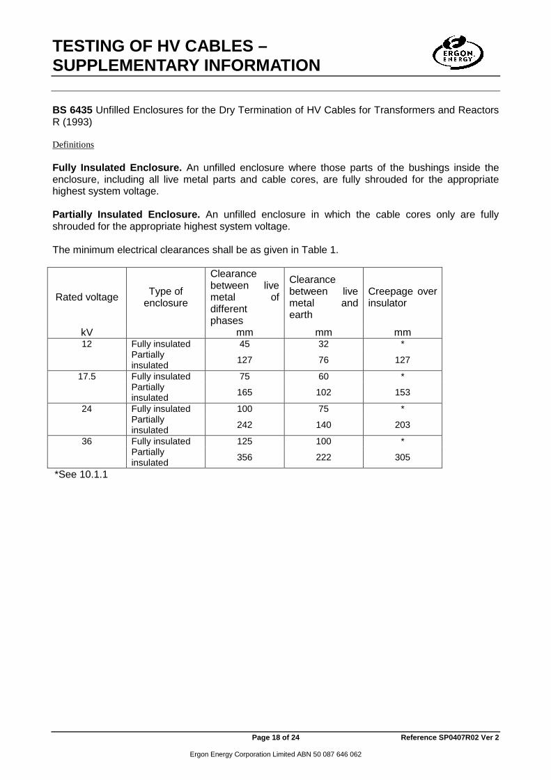
BS 6435 Unfilled Enclosures for the Dry Termination of HV Cables for Transformers and Reactors R (1993) Definitions Fully Insulated Enclosure. An unfilled enclosure where those parts of the bushings inside the enclosure, including all live metal parts and cable cores, are fully shrouded for the appropriate highest system voltage. Partially Insulated Enclosure. An unfilled enclosure in which the cable cores only are fully shrouded for the appropriate highest system voltage. The minimum electrical clearances shall be as given in Table 1.
Rated voltage Type of enclosure
Clearance between live metal of different phases
Clearance between live metal and earth
Creepage over insulator
kV mm mm mm 12 Fully insulated 45 32 *
Partially insulated 127 76 127
17.5 Fully insulated 75 60 *
Partially insulated 165 102 153
24 Fully insulated 100 75 *
Partially insulated 242 140 203
36 Fully insulated 125 100 *
Partially insulated 356 222 305
*See 10.1.1

TESTING OF HV CABLES – SUPPLEMENTARY INFORMATION
Page 19 of 24 Reference SP0407R02 Ver 2
Ergon Energy Corporation Limited ABN 50 087 646 062
5. APPENDIX C: STANDARDS THAT MAY PROVIDE FURTHER INFORMATION
ASTM D 149 and IEC 60243 Part 1 provide a list of ASTM / IEC standards for various insulating materials. ASTM D 149 REV A Standard Test Method for Dielectric Breakdown Voltage and Dielectric Strength of Solid Electrical Insulating Materials at Commercial Power Frequencies ASTM D 2477 - Standard Test Method for Dielectric Breakdown Voltage and Dielectric Strength of Insulating Gases at Commercial Power Frequencies ASTM D 3283 - Standard Specification for Air as an Electrical Insulating Material ASTM D 3426 - Standard Test Method for Dielectric Breakdown Voltage and Dielectric Strength of Solid Electrical Insulating Materials Using Impulse Waves R(2004) ASTM D 3755 - Standard Test Method for Dielectric Breakdown Voltage and Dielectric Strength of Solid Electrical Insulating Materials under Direct-Voltage Stress R(2004) IEC 60085 - Thermal Evaluation and Classification of Electrical Insulation Second Edition IEC 61472 - Live Working - Minimum Approach Distances - Method of Calculation First Edition IEC 60243-1 Electrical Strength of Insulating Materials - Test Methods - Part 1: Tests at Power Frequencies Second Edition IEC 60243-2 Electric Strength of Insulating Materials - Test Methods - Part 2: Additional Requirements for Tests Using Direct Voltage Second Edition IEC 60243-3 Electric Strength of Insulating Materials - Test Methods - Part 3: Additional Requirements for 1,2/50 us Impulse Tests Second Edition AS/NZS 1660.3:1998 Test methods for electric cables, cords and conductors; Method 3: Electrical tests AS/NZS 3808:2000 Insulating and sheathing materials for electric cables ASTM F 819 Standard Terminology Relating to Electrical Protective Equipment for Workers E(2000) IEEE 48 Standard Test Procedures and Requirements for Alternating-Current Cable Terminations 2.5 kV Through 765 kV R(2003) IEEE 82 Standard Test Procedure for Impulse Voltage Tests on Insulated Conductors IEEE 400 Guide for Field Testing and Evaluation of the Insulation of Shielded Power Cable Systems IEEE 576 Recommended Practice for Installation, Termination, and Testing of Insulated Power Cable as Used in Industrial and Commercial Applications IEEE 404 Standard for Extruded and Laminated Dielectric Shielded Cable Joints Rated 2500 V to 500 000 V IEC 60060-1 High-Voltage Test Techniques Part 1: General Definitions and Test Requirements Second Edition; Corrigendum-03/1990; Corrigendum-03/1992 IEC 60060-2 High-Voltage Test Techniques Part 2: Measuring Systems Second Edition; Amendment 1-1996; Replaces 60060-3: 1976 IEC 60230 Impulse Tests on Cables and Their Accessories First Edition IEC 61442 Electric Cables - Test Methods for Accessories for Power Cables with Rated Voltages from 6 kV (Um=7,2 kV) up to 30 kV (Um=36 kV) First Edition
TESTING OF HV CABLES – SUPPLEMENTARY INFORMATION
Page 20 of 24 Reference SP0407R02 Ver 2
Ergon Energy Corporation Limited ABN 50 087 646 062
ELECTRICAL INSULATING SLEEVING AND TUBING (HEAT SHRINK) IEC 60684-1 Flexible insulating sleeving Part 1: Definitions and general requirements Second Edition IEC 60684-2 Flexible Insulating Sleeving - Part 2: Methods of Test Edition 2.1; Edition 2: 1997 Consolidated with Amendment 1:2003 IEC 60684-3-100 TO 105 Flexible Insulating Sleeving - Part 3: Specifications for Individual Types of Sleeving - Sheets 100 to 105: Extruded PVC Sleeving Second Edition IEC 60684-3-116 AND 117 Flexible insulating sleeving Part 3: Specifications for individual types of sleeving Sheets 116 and 117: Extruded polychloroprene General purpose Second Edition IEC 60684-3-121 TO 124 Flexible Insulating Sleeving - Part 3: Specifications for Individual Types of Sleeving - Sheets 121 and 124: Extruded Silicone Sleeving Second Edition IEC 60684-3-136 Flexible Insulating Sleeving - Part 3: Specification for Individual Types of Sleeving - Sheet 136: Extruded Fluorosilicone Sleeving - General Purpose First Edition; Corrigendum: 02-1999 IEC 60684-3-145 TO 147 Flexible Insulating Sleeving - Part 3: Specifications for Individual Types of Sleeving - Sheets 145 to 147: Extruded PTFE Sleeving First Edition IEC 60684-3-151 Flexible Insulating Sleeving - Part 3: Specifications for Individual Types of Sleeving - Sheet 151: Extruded PVC/Nitrile Rubber - General Purpose First Edition IEC 60684-3-201 Specification for Flexible Insulating Sleeving Part 3: Specification Requirements for Individual Types of Sleeving Sheet 201: Heat Shrinkable Sleeving, General Purpose, Flexible, Cross-Linked PVC, Shrink Ratio 2:1 First Edition IEC 60684-3-209 Flexible insulating sleeving Part 3: Specifications for individual types of sleeving Sheet 209: Heat-shrinkable polyolefin sleeving, general purpose, flame retarded, shrink ratio 2:1 Second Edition IEC 60684-3-211 Flexible Insulating Sleeving - Part 3: Specifications for Individual Types of Sleeving - Sheet 211: Heat-Shrinkable Sleeving, Semi-Rigid Polyolefin, Shrink Ratio 2:1 Second Edition IEC 60684-3-212 Flexible Insulating Sleeving - Part 3: Specifications for Individual Types of Sleeving - Sheet 212: Heat-Shrinkable Polyolefin Sleeving, Flame Retarded, Shrink Ratio 2:1 First Edition IEC 60684-3-213 Flexible Insulating Sleeving - Part 3: Specifications for Individual Types of Sleeving - Sheet 213: Heat-Shrinkable Polyolefin Sleeving, Not Flame Retarded, Shrink Ratio 2:1 First Edition IEC 60684-3-214 Flexible Insulating Sleeving - Part 3: Specifications for Individual Types of Sleeving - Sheet 214: Heat-Shrinkable, Polyolefin Sleeving, Not Flame Retarded, Shrink Ratio 3:1 - Thick and Medium Wall First Edition IEC 60684-3-216 Flexible Insulating Sleeving - Part 3: Specifications for Individual Types of Sleeving - Sheet 216: Heat-Shrinkable, Flame-Retarded, Limited-Fire-Hazard Sleeving First Edition; Amendment 1: 02/2003 IEC 60684-3-217 Flexible Insulating Sleeving - Part 3: Specifications for Individual Types of Sleeving - Sheet 217: Heat-Shrinkable Polyolefin Sleeving, Flame Retarded, Shrink Ratio 3:1 First Edition IEC 60684-3-218 Flexible Insulating Sleeving - Part 3: Specifications for Individual Types of Sleeving - Sheet 218: Heat-Shrinkable Polyolefin Sleeving, Not Flame Retarded, Shrink Ratio 3:1 First Edition IEC 60684-3-228 Flexible Insulating Sleeving - Part 3: Specifications for Individual Types of Sleeving - Sheet 228: Heat-Shrinkable Semi-Rigid, Polyvinylidene Fluoride Sleeving, Flame Retarded, Fluid Resistant, Shrink Ratio 2:1 First Edition IEC 60684-3-229 Flexible insulating sleeving Part 3: Specifications for individual types of sleeving Sheet 229: Heat-shrinkable semi-flexible, polyvinylidene fluoride sleeving, flame retarded, fluid resistant, shrink ratio 2:1 First Edition IEC 60684-3-233 Flexible Insulating Sleeving - Part 3: Specifications for Individual Types of Sleeving - Sheet 233: Heat-Shrinkable Fluoroelastomer Sleeving, Flame Retarded, Fluid Resistant, Shrink Ratio 2:1 First Edition IEC 60684-3-240 TO 243 Flexible Insulating Sleeving - Part 3: Specifications for Individual Types of Sleeving - Sheets 240 to 243: Heat-Shrinkable PTFE Sleeving Second Edition IEC 60684-3-246 Flexible Insulating Sleeving - Part 3: Specifications for Individual Types of Sleeving - Sheet 246: Heat-Shrinkable Polyolefin Sleeving, Dual-Wall, Not Flame-Retarded Second Edition IEC 60684-3-271 Flexible Insulating Sleeving - Part 3: Specifications for Individual Types of Sleeving - Sheet 271: Heat-Shrinkable Elastomer Sleeving, Flame Retarded, Fluid Resistant, Shrink Ratio 2:1 First Edition IEC 60684-3-272 Flexible Insulating Sleeving - Part 3: Specifications for Individual Types of Sleeving - Sheet 272: Heat-Shrinkable Elastomer Sleeving, Flame Retarded, Fluid Resistant, Shrink Ratio 2:1, Thin Wall First Edition IEC 60684-3-300 Flexible Insulating Sleeving - Part 3: Specifications for Individual Types of Sleeving - Sheet 300: Glass Textile Fibre Sleeving, Braided, Uncoated IEC 60684-3-320 Flexible Insulating Sleeving - Part 3: Specifications for Individual Types of Sleeving - Sheet 320: Polyethylene Terephthalate Textile Sleeving, Lightly Impregnated Second Edition

TESTING OF HV CABLES – SUPPLEMENTARY INFORMATION
Page 21 of 24 Reference SP0407R02 Ver 2
Ergon Energy Corporation Limited ABN 50 087 646 062
IEC 60684-3-340 TO 342 Flexible insulating sleeving Part 3: Specifications for individual types of sleeving Sheets 340 to 342: Expandable braided polyethylene terephthalate textile sleeving Second Edition IEC 60684-3-343 TO 345 Flexible Insulating Sleeving - Part 3: Specification for Individual Types of Sleeving - Sheets 343 to 345: Expandable Braided Ethylene Chlorotrifluoroethylene (E-CTFE) Textile Sleeving, Uncoated Second Edition IEC 60684-3-400 TO 402 Flexible Insulating Sleeving - Part 3: Specifications for Individual Types of Sleeving - Sheets 400 to 402: Glass Textile Sleeving with Silicone Elastomer Coating Second Edition IEC 60684-3-403 TO 405 Flexible Insulating Sleeving - Part 3: Specification Individual Types of Sleeving - Sheets 403 to 405: Glass Textile Sleeving with Acrylic Based Coating Second Edition IEC 60684-3-406 TO 408 Flexible insulating sleeving Part 3: Specifications for individual types of sleeving Sheets 406 to 408: Glass textile sleeving with PVC coating Second Edition IEC 60684-3-409 Flexible Insulating Sleeving - Part 3: Specifications for Individual Types of Sleeving - Sheet 409: Glass Textile Sleeving with Polyurethane (PUR)-Based Coating First Edition IEC 60684-3-420 TO 422 Flexible Insulating Sleeving - Part 3: Specification for Individual Types of Sleeving - Sheets 420 to 422: Polyethylene Terephthalate Textile Sleeving with Acrylic Based Coating Second Edition ASTM D 2671 - Standard Test Methods for Heat-Shrinkable Tubing for Electrical Use ASTM D 2902 - Standard Specification for Fluoropolymer Resin Heat-Shrinkable Tubing for Electrical Insulation ASTM D 2903 - Standard Specification for Crosslinked Chlorinated Polyolefin Heat-Shrinkable Tubing for Electrical Insulation R(1998) ASTM D 3144 - Standard Specification for Crosslinked Poly(Vinylidene Fluoride) Heat-Shrinkable Tubing for Electrical Insulation ASTM D 3149 - Standard Specification for Crosslinked Polyolefin Heat-Shrinkable Tubing for Electrical Insulation ASTM D 3150 - Standard Specification for Crosslinked and Noncrosslinked Poly (Vinyl Chloride) Heat-Shrinkable Tubing for Electrical Insulation MILSPEC MIL-DTL-23053/10D CANC NOTICE 1 - INSULATION SLEEVING, ELECTRICAL, HEAT SHRINKABLE, SILICONE RUBBER, FLEXIBLE (REFER TO SAE AMS-DTL-23053/10) MILSPEC MIL-DTL-23053/11C CANC NOTICE 1 - INSULATION SLEEVING, ELECTRICAL, HEAT SHRINKABLE, FLUORINATED ETHYLENE PROPYLENE, NON-CROSSLINKED (REFER TO SAE AMS-DTL-23053/11) MILSPEC MIL-DTL-23053/12C CANC NOTICE 1 - INSULATION SLEEVING, ELECTRICAL, HEAT SHRINKABLE, POLYTETRAFLUOROETHYLENE (REFER TO SAE AMS-DTL-23053/12) MILSPEC MIL-DTL-23053/13B CANC NOTICE 1 - INSULATION SLEEVING, ELECTRICAL, HEAT SHRINKABLE, FLUOROELASTOMER, FLEXIBLE (REFER TO SAE ASM-DTL-23053/13) MILSPEC MIL-DTL-23053/14B CANC NOTICE 1 - INSULATION SLEEVING, ELECTRICAL, HEAT SHRINKABLE, ETHYLENE-TETRAFLUOROETHYLENE FLUOROPOLYMER, SEMI-RIGID (REFER TO SAE AMS-DTL-23053/14) MILSPEC MIL-DTL-23053/15B CANC NOTICE 1 - INSULATION SLEEVING, ELECTRICAL, HEAT SHRINKABLE, POLYOLEFIN, HEAVY-WALL, COATED, FLEXIBLE, OUTER WALL CROSSLINKED (REFER TO SAE AMS-DTL-23053/15) MILSPEC MIL-DTL-23053/16B CANC NOTICE 1 - INSULATION SLEEVING, ELECTRICAL, HEAT SHRINKABLE, CROSSLINKED, ELASTOMERIC POLYOLEFIN, FLEXIBLE (REFER TO SAE AMS-DTL-23053/16) MILSPEC MIL-DTL-23053/17B CANC NOTICE 1 - INSULATION SLEEVING, ELECTRICAL, HEAT SHRINKABLE, FLAME RETARDED, MODIFIED POLYOLEFIN, FLEXIBLE, CROSSLINKED (REFER TO SAE AMS-DTL-23053/17) MILSPEC MIL-DTL-23053/18B CANC NOTICE 1 - INSULATION SLEEVING, ELECTRICAL, HEAT SHRINKABLE, MODIFIED FLUOROPOLYMER, CROSSLINKED (REFER TO SAE AMS-DTL-23053/18) MILSPEC MIL-DTL-23053/1C CANC NOTICE 1 - INSULATION SLEEVING, ELECTRICAL, HEAT SHRINKABLE, CROSSLINKED CHLORINATED POLYOLEFIN, FLEXIBLE (REFER TO SAE AMS-DTL-23053/1) MILSPEC MIL-DTL-23053/4D CANC NOTICE 1 - INSULATION SLEEVING, ELECTRICAL, HEAT SHRINKABLE, POLYOLEFIN, DUAL-WALL, OUTER WALL CROSSLINKED (REFER TO SAE AMS-DTL-23053/4) MILSPEC MIL-DTL-23053/5C CANC NOTICE 1- INSULATION SLEEVING, ELECTRICAL, HEAT SHRINKABLE, POLYOLEFIN, FLEXIBLE, CROSSLINKED (REFER TO SAE AMS-DTL-23053/5)

TESTING OF HV CABLES – SUPPLEMENTARY INFORMATION
Page 22 of 24 Reference SP0407R02 Ver 2
Ergon Energy Corporation Limited ABN 50 087 646 062
MILSPEC MIL-DTL-23053/6D CANC NOTICE 1 - INSULATION SLEEVING, ELECTRICAL, HEAT SHRINKABLE, POLYOLEFIN, SEMI-RIGID, CROSSLINKED (REFER TO SAE AMS-DTL-23056/6) MILSPEC MIL-DTL-23053/7C CANC NOTICE 1 - INSULATION SLEEVING, ELECTRICAL, HEAT SHRINKABLE, POLYETHYLENE TEREPHTHALATE, NON-CROSSLINKED (REFER TO SAE AMS-DTL-23053/7) MILSPEC MIL-DTL-23053/8C CANC NOTICE 1 - INSULATION SLEEVING, ELECTRICAL, HEAT SHRINKABLE, POLYVINYLIDENE FLUORIDE, SEMI-RIGID, CROSSLINKED (REFER TO SAE AMS-DTL-23053/8) MILSPEC MIL-DTL-23053E CANC NOTICE 3 - INSULATION SLEEVING, ELECTRICAL, HEAT SHRINKABLE, GENERAL SPECIFICATION FOR (REFER TO SAE AMS-DTL-23053) MILSPEC MIL-I-13042A CANC NOTICE 1 - INSULATION SLEEVING, THERMAL, TUBULAR, FLEXIBLE (REFER TO A-A-52152) MILSPEC MIL-I-13548A CANC NOTICE 1 - INSULATION SLEEVING, ELECTRICAL (CABLE SPLICING) FT-96, FT-97, FT-98, AND FT-472 MILSPEC MIL-I-23053/2C CANC NOTICE 2 - INSULATION SLEEVING, ELECTRICAL, HEAT SHRINKABLE, POLYVINYL CHLORIDE, FLEXIBLE, CROSSLINKED AND NON-CROSSLINKED (REFER TO SAE AMS-I-23053/2) MILSPEC MIL-I-23053/3A CANC NOTICE 2 - INSULATION SLEEVING, ELECTRICAL, HEAT SHRINKABLE, POLYVINYL CHLORIDE, SEMI RIGID, CROSSLINKED AND NON-CROSSLINKED (REFER TO SAE AMS-I-23053/3) MILSPEC MIL-I-3190/2A (1) - INSULATION SLEEVING, ELECTRICAL, FLEXIBLE, COATED, CLASS 130, TYPE B, CATEGORY B MILSPEC MIL-I-3190/3A - INSULATION SLEEVING, ELECTRICAL, FLEXIBLE, COATED, CLASS 155, TYPE A, CATEGORY A MILSPEC MIL-I-3190/5B - INSULATION SLEEVING, ELECTRICAL, FLEXIBLE, COATED, CLASS 200, TYPE C, CATEGORY C MILSPEC MIL-I-3190/6A - INSULATION SLEEVING, ELECTRICAL, FLEXIBLE, COATED, CLASS 200, TYPE D, CATEGORY C MILSPEC MIL-I-3190/7A - INSULATION SLEEVING, ELECTRICAL, FLEXIBLE, COATED CLASS 220 DEG. C, TYPE E, CATEGORY C MILSPEC MIL-I-3190/8A - INSULATION SLEEVING, ELECTRICAL, FLEXIBLE, SILICONE COATED, CLASS 220 DEG. C, TYPE D CATEGORY C MILSPEC MIL-I-3190/9 (1) - INSULATION SLEEVING, ELECTRICAL, FLEXIBLE, SILICONE COATED CLASS 240 DEG. C, TYPE D, CATEGORY C MILSPEC MIL-I-3190F (2) - INSULATION SLEEVING, ELECTRICAL, FLEXIBLE, COATED, GENERAL SPECIFICATION FOR MILSPEC MIL-I-47100 NOTICE 4 - INSULATION SLEEVING, FLEXIBLE, BRAIDED, 200 DEGREES CELSIUS (HIGH TEMPERATURE POLYAMIDE) MILSPEC MIL-I-47203 CANC NOTICE 1 - INSULATION SLEEVING, ELECTRICAL, BRAIDED (USE MIL-S-47053) MILSPEC MIL-I-7444D NOTICE 2 - INSULATION SLEEVING, ELECTRICAL, FLEXIBLE MILSPEC MIL-I-82799 CANC NOTICE 1 - INSULATION SLEEVING, ELECTRICAL, HEAT-SHRINKABLE
ELECTRICAL INSULATING TAPES ASTM D 1458 - Standard Test Methods for Fully Cured Silicone Rubber-Coated Glass Fabric and Tapes for Electrical Insulation ASTM D 1459 - Standard Specification for Silicone Varnished Glass Cloth and Tape for Electrical Insulation R(2003) ASTM D 1931 - Standard Specification for Fully Cured Silicone Rubber-Coated Glass Fabric and Tapes for Electrical Insulation
TESTING OF HV CABLES – SUPPLEMENTARY INFORMATION
Page 23 of 24 Reference SP0407R02 Ver 2
Ergon Energy Corporation Limited ABN 50 087 646 062
ASTM D 2301 - Standard Specification for Vinyl Chloride Plastic Pressure-Sensitive Electrical Insulating Tape ASTM D 2400 - Standard Specification for Varnished Glass-Polyester Cloth Used for Electrical Insulation ASTM D 2484 - Standard Specification for Polyester Film Pressure-Sensitive Electrical Insulating Tape ASTM D 2686 - Standard Specification for Polytetrafluoroethylene-Backed Pressure-Sensitive Electrical Insulating Tape ASTM D 3005 - Standard Specification for Low-Temperature Resistant Vinyl Chloride Plastic Pressure-Sensitive Electrical Insulating Tape ASTM D 3006 - Standard Specification for Polyethylene Plastic Pressure-Sensitive Electrical Insulating Tape ASTM D 2754 - Standard Specification for High-Temperature Glass Cloth Pressure-Sensitive Electrical Insulating Tape ASTM D 372 - Standard Specification for Flexible Treated Sleeving Used for Electrical Insulation ASTM D 4388 - Standard Specification for Nonmetallic Semi-Conducting and Electrically Insulating Rubber Tapes ASTM D 2518 - Standard Specification for Woven Glass Fabrics for Electrical Insulation ASTM D 3308 - Standard Specification for PTFE Resin Skived Tape IEC 60454-1 - Specifications for Pressure-Sensitive Adhesive Tapes for Electrical Purposes Part 1: General Requirements Second Edition IEC 60454-2 - Specification for Pressure-Sensitive Adhesive Tapes for Electrical Purposes Part 2: Methods of Test Second Edition IEC 60454-3-1 - Pressure-sensitive adhesive tapes for electrical purposes Part 3 Specifications for individual materials Sheet 1: PVC film tapes with pressure-sensitive adhesive Edition 2.1; Edition 2: 1998 Consolidated with Amendment 1: 2001 IEC 60454-3-10 - Pressure-Sensitive Adhesive Tapes for Electrical Purposes Part 3: Specifications for Individual Materials - Sheet 10: Requirements for Cellulose-Acetate-Butyrate Film Tapes with Rubber Thermosetting Adhesive First Edition IEC 60454-3-11 - Pressure-Sensitive Adhesive Tapes for Electrical Purposes - Part 3: Specifications for Individual Materials - Sheet 11: Combination Tapes Made of Creped Cellulosic Paper and Polyethylene Terephthalate Film with Rubber Thermosetting Adhesive First Edition IEC 60454-3-12 - Pressure-Sensitive Adhesive Tapes for Electrical Purposes - Part 3: Specifications for Individual Materials - Sheet 12: Polyethylene Film Tapes with Pressure-Sensitive Adhesive First Edition IEC 60454-3-13 - Pressure-Sensitive Adhesive Tapes for Electrical Purposes Part 3: Specifications for Individual Materials - Sheet 13: Requirements for Combined Cellulose-Viscose Woven Fabric Tapes, One Side Covered with a Thermoplastic Material, the Other Side with Rubber Thermosetting Adhesive First Edition IEC 60454-3-14 - Pressure-Sensitive Adhesive Tapes for Electrical Purposes - Part 3: Specifications for Individual Materials - Sheet 14: Polytetrafluoroethylene Film Tapes with Pressure-Sensitive Adhesive First Edition IEC 60454-3-15 - Pressure-Sensitive Adhesive Tapes for Electrical Purposes - Part 4: Specifications for Individual Materials - Sheet 15: Polyester Film/Polyester Non-Woven Combinations with Rubber Thermosetting Adhesive First Edition IEC 60454-3-16 - Pressure-sensitive adhesive tapes for electrical purposes Part 3: Specifications for individual materials Sheet 16: Polyester film/glass filament combinations with pressure-sensitive adhesive First Edition IEC 60454-3-17 - Pressure-Sensitive Adhesive Tapes for Electrical Purposes - Part 3: Specifications for Individual Materials - Sheet 17: Polyester/Epoxy Combinations with Pressure-Sensitive Adhesive First Edition IEC 60454-3-18 - Pressure-sensitive adhesive tapes for electrical purposes Part 3: Specifications for individual materials Sheet 18: Polypropylene film tapes with pressure-sensitive adhesive First Edition IEC 60454-3-19 - Pressure-sensitive adhesive tapes for electrical purposes Part 3: Specifications for individual materials Sheet 19: Tapes made from various backing materials with pressure-sensitive adhesive on both sides First Edition IEC 60454-3-2 - Pressure-Sensitive Adhesive Tapes for Electrical Purposes - Part 3: Specifications for Individual Materials - Sheet 2: Polyester Film Tapes with Rubber Thermosetting or Acrylic Crosslinked Adhesives Second Edition IEC 60454-3-3 - Pressure-Sensitive Adhesive Tapes for Electrical Purposes - Part 3: Specifications for Individual Materials - Sheet 3: Polyester Film Tapes with Rubber Thermoplastic Adhesive Second Edition IEC 60454-3-4 - Pressure-Sensitive Adhesive Tapes for Electrical Purposes - Part 3: Specifications for Individual Materials Sheet 4: Cellulosic Paper, Creped, with Rubber Thermosetting Adhesive Second Edition

TESTING OF HV CABLES – SUPPLEMENTARY INFORMATION
Page 24 of 24 Reference SP0407R02 Ver 2
Ergon Energy Corporation Limited ABN 50 087 646 062
IEC 60454-3-5 - Pressure-Sensitive Adhesive Tapes for Electrical Purposes - Part 3: Specifications for Individual Materials - Sheet 5: Cellulosic Paper, Non-Creped, with Rubber Thermosetting Adhesive Second Edition IEC 60454-3-6 - Pressure-Sensitive Adhesive Tapes for Electrical Purposes - Part 3: Specifications for Individual Materials - Sheet 6: Polycarbonate Film Tapes with Acrylic Thermoplastic Adhesive Second Edition IEC 60454-3-7 - Pressure-Sensitive Adhesive Tapes for Electrical Purposes - Part 3: Specifications for Individual Materials - Sheet 7: Polyimide Film Tapes with Pressure-Sensitive Adhesive Second Edition IEC 60454-3-8 - Pressure-Sensitive Adhesive Tapes for Electrical Purposes - Part 3: Specifications for Individual Materials - Sheet 8: Glass Fabric with Pressure-Sensitive Adhesive Second Edition IEC 60454-3-9 - Pressure-Sensitive Adhesive Tapes for Electrical Purposes - Part 3: Specifications for Individual Materials - Sheet 9: Cellulose Acetate Woven Fabric Tapes with Rubber Thermosetting Adhesives First Edition
ELECTRICAL INSULATING PAPERS Notes from ESAA Short Course “Transformer Technology” September 1999. IEC 60554-1 - Specification for Cellulosic Papers for Electrical Purposes Part 1: Definitions and General Requirements First Edition; Erratum-03/1979; Amendment 1-1983 IEC 60554-2 - Cellulosic papers for electrical purposes Part 2: Methods of test Second Edition IEC 60554-3-1 - Specification for Cellulosic Papers for Electrical Purposes Part 3: Specifications for Individual Materials Sheet 1: General Purpose Electrical Paper First Edition IEC 60554-3-2 - Specification for Cellulosic Papers for Electrical Purposes Part 3: Specifications for Individual Materials Sheet 2: Capacitor Paper First Edition IEC 60554-3-3 - Specification for Cellulosic Papers for Electrical Purposes Part 3: Specification for Individual Materials Sheet 3: Crepe Paper First Edition IEC 60554-3-4 - Specification for Cellulosic Papers for Electrical Purposes Part 3: Specifications for Individual Materials Sheet 4: Electrolytic Capacitor Paper First Edition IEC 60554-3-5 - Specification for Cellulosic Papers for Electrical Purposes Part 3: Specifications for Individual Materials Sheet 5: Special Papers First Edition IEC 60641-1 - Specification for Pressboard and Presspaper for Electrical Purposes Part 1: Definitions and General Requirements First Edition; (Amendment 1-1993) (CENELEC EN 60641-1: 1995) IEC 60641-2 - Specification for Pressboard and Presspaper for Electrical Purposes Part 2: Methods of Test First Edition; Amendment 1-1993; Corrigendum-10/1994; CENELEC EN 60 641-2: 1995 IEC 60641-3-1 - Specification for Pressboard and Presspaper for Electrical Purposes Part 3: Specifications for Individual Materials - Sheet 1: Requirements for Pressboard, Types B.0.1, B.2.1, B.2.3, B.3.1, B.3.3, B.4.1, B.4.3, B.5.1, B.6.1 and B.7.1 First Edition IEC 60641-3-2 - Specification for Pressboard and Presspaper for Electrical Purposes Part 3: Specifications for Individual Materials - Sheet 2: Requirements for Presspaper, Types P.2.1, P.4.1, P.4.2, P.4.3, P.6.1 and P.7.1 First Edition; CENELEC EN 60641-3-2: 1994 IEC 60819-1 - Non-Cellulosic Papers for Electrical Purposes Part 1: Definitions and General Requirements Second Edition; (CENELEC EN 60819-1: 1995) (Amendment 1-1996) IEC 60819-2 - Non-Cellulosic Papers for Electrical Purposes - Part 2: Methods of Test First Edition IEC 60819-3-1 - Non-Cellulosic Papers for Electrical Purposes - Part 3: Specification for Individual Materials - Sheet 1: Filled Glass Paper First Edition IEC 60819-3-2 - Non-Cellulosic Papers for Electrical Purposes - Part 3: Specifications for Individual Materials - Sheet 2: Hybrid Inorganic-Organic Paper First Edition IEC 60819-3-3 - Specification for Non- Cellulosic Papers for Electrical Purposes Part 3: Specifications for Individual Materials Sheet 3: Unfilled Aramid (Aromatic Polyamide) Papers First Edition IEC 60819-3-4 - Non-Cellulosic Papers for Electrical Purposes - Part 3: Specifications for Individual Materials - Sheet 4: Aramid Fibre Paper Containing Not More Than 50 % of Mica Particles First Edition ASTM D 4063 - Standard Specification for Pressboard for Electrical Insulating Purposes ASTM D 1305 - Standard Specification for Electrical Insulating Paper and Paperboard - Sulfate (Kraft) Layer Type