
Testing Efficiency of Storage in the Subsurface: Frio ...
31
Testing Efficiency of Storage in the Subsurface: Frio Brine Pilot Experiment GCCC Digital Publication Series #04-01 Susan D. Hovorka Christine Doughty Mark H. Holtz Cited as : Hovorka, S.D., Doughty, C., and Holtz, M. H., 2004, Testing efficiency of storage in the subsurface: Frio Brine Pilot Experiment, in 7th International Conference on Greenhouse Gas Control Technologies, Vancouver, Canada, September 5–9, unpaginated [5 p.]. GCCC Digital Publication Series #04-01. Keywords : Frio Brine Pilot Experiment- Stages, Reservoir Model, Geologic Sequestration- Residual Saturation, Monitoring and Verification, Pre-Injection Geophysics
Transcript of Testing Efficiency of Storage in the Subsurface: Frio ...
Testing Efficiency of Storage in the Subsurface: Frio Brine Pilot Experiment
GCCC Digital Publication Series #04-01
Susan D. Hovorka Christine Doughty
Mark H. Holtz
Cited as: Hovorka, S.D., Doughty, C., and Holtz, M. H., 2004, Testing efficiency of storage in the subsurface: Frio Brine Pilot Experiment, in 7th International Conference on Greenhouse Gas Control Technologies, Vancouver, Canada, September 5–9, unpaginated [5 p.]. GCCC Digital Publication Series #04-01.
Keywords: Frio Brine Pilot Experiment- Stages, Reservoir Model, Geologic Sequestration- Residual Saturation, Monitoring and Verification, Pre-Injection Geophysics
___________________
*Corresponding author: Tel. (512) 471-4863, Fax. (512) 471-0140, Email: [email protected]
PAPER 574
TESTING EFFICIENCY OF STORAGE IN THE SUBSURFACE: FRIO BRINE PILOT EXPERIMENT
Susan D. Hovorka1*, Christine Doughty2, & Mark H. Holtz1,
1 Gulf Coast Carbon Center, Bureau of Economic Geology, Jackson School of Geosciences, Box X, The University of Texas at Austin, Austin TX 78713-8924
2Lawrence Berkeley National Laboratory, Berkeley CA, Cyclotron Road Mail Stop 90R1116 Berkeley, CA 94720
Abstract
How can we demonstrate that subsurface storage is an effective method of reducing emissions of CO2 to the atmosphere? The Frio Brine Pilot Experiment is designed to test storage performance of a typical subsurface environment in an area where large-volume sources and sinks are abundant, near Houston, Texas, USA. We employed extensive preexperiment characterization and modeling to identify significant factors that increase or decrease risk of leakage from the injection zone. We then designed the experiment to focus on those factors, as well as to test for presence or absence of events that are not expected.
A fully developed reservoir model of heterogeneous reworked fluvial sandstones of the Frio Formation documents three-dimensional compartmentalization of the injection horizon by faulting associated with salt-dome intrusion and growth. Modeling using the TOUGH2 simulator showed that a significant source of uncertainty for subsurface performance of injected CO2 is residual CO2 saturation during storage. If initial displacement of water during injection is efficient and capillary effects create the expected residual saturation of 30 percent CO2, the volume occupied by the plume will be limited, and long-term storage can be expected even in an open system. If, however, during injection, CO2 moves out from the injection well along high-permeability pathways, it may not contact most pores, and residual saturation will have a smaller effect on storage. Our experiment is therefore designed to monitor plume geometry and CO2 saturation near the injection well and closely spaced observation well. Leakage out of the injection zone as a result of well engineering or other flaws in the seal is also monitored in the sandstone immediately overlying the injection zone and at the surface using multiple techniques.
Permitting strategies include cooperation among two State agencies, as well as Federal NEPA assessment, because of the innovative aspects of the experiment.
Introduction
Diverse stationary sources of CO2 concentrated on the margins of the Gulf of Mexico include refineries, chemical industries, and electric utilities. Using an international-source database [1], we estimated that annual emissions from 450 stationary sources total 520,000 Gg CO2 [1]. Potential risks from business-as-usual atmospheric release of CO2 are significant for this region [2]. Relative sea-level rise, increased storm severity, and resulting flooding are already of concern in this low-relief coastal area. Increase in these risks introduced by climatic change could be costly. Increased tropicalization is also of concern in this already warm region. Other negative effects of combustion on the atmosphere in warm areas, such as ground-level ozone, have increased regional concern about reducing emissions of the byproducts of combustion [3].
In our previous study [4], we found that the Gulf Coast region has a high potential for geologic sequestration of CO2. Thick and permeable sandstones and extensive shales in the subsurface of this region are well known because of hydrocarbon production, and large opportunities are recognized for revitalization of reservoirs in decline through a combination of storage and enhanced recovery. For the experiment, however, selection of injection into a brine-bearing sandstone was made. The result is to focus the experiment on storage as a step needed to develop through
incentives the combination of storage and enhanced recovery. The site is within a historic oil field in which subsurface data are abundant, surface and subsurface infrastructure is available, and additional environmental impact has been minimized.
Scope of Experiment
The experiment is being conducted in nine stages: (1) site selection, with general characterization and scoping modeling; (2) geologic characterization; (3) modeling and experimental-design refinement; (4) permitting; (5) site preparation; (6) detailed site characterization; (7) baseline monitoring; (8) injection and syninjection monitoring; and (9) postinjection monitoring. At the time of writing, June 2004, stages 1 through 5 have been completed, and stages 6 and 7 are under way, with stage 8 scheduled for early fall 2004. Results of the completed stages are reviewed in this paper. The experiment will use 3,000 tons of CO2 from refinery sources trucked to the site and injected within a 3-week time period. A new well has been drilled for injection 30 m downdip of an existing oil production well that has been retrofitted as an in-zone observation well. A multidisciplinary team from nine institutions and companies are collaborating to field interconnected measurement, monitoring, and verification (MMV) technologies. These include downhole seismic (cross-well and vertical seismic profiling [VSP]), wireline logging for saturation, downhole geochemical sampling and pumping fluids to the surface to monitor geochemical changes, stable isotopic, noble gas, and introduced perfluorocarbon tracers, aquifer, unsaturated zone, and atmospheric monitoring.
Geologic Setting
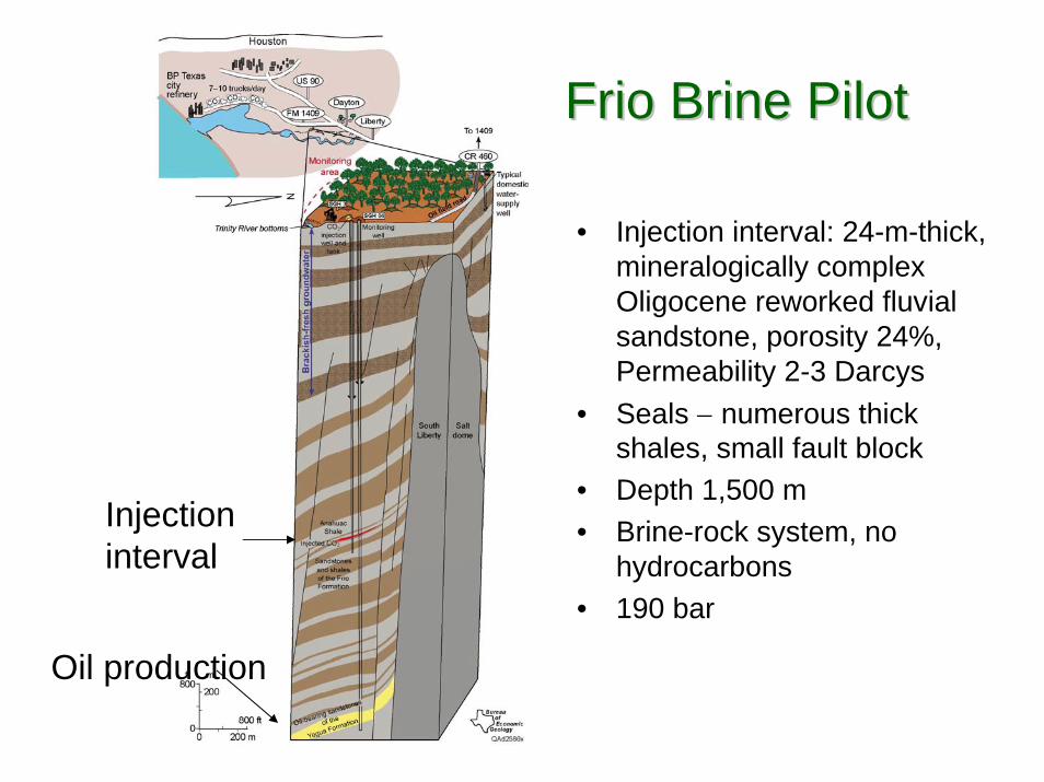
During site selection we determined that the target is 250- to 400-m-thick, regionally extensive, Oligocene Frio sandstone, which underlies many sources along the Gulf Coast. To reduce perceived risk and liability, we elected to inject into a fault-bounded compartment, which are common around salt domes. In order to develop a detailed characterization at minimal expense and conduct the experiment with minimal environmental impact, we decided to develop the experimental site in an oil field. We proposed a site in South Liberty oil field, where access to several idle wells and a recent 3-D seismic survey were donated by Texas American Resources Company. During scoping modeling, we realized that the volume of rock through which CO2 passes is critical to assuring that breakthrough to the observation well will occur. This realization resulted in our selecting the close (30-m) well spacing and the upper part (10 m) of a 23-m-thick upper Frio “C” sandstone as the injection interval. The top Frio “C” lies at depths of about 1,500 m. The seal on the injection interval is shale overlying the “C” sandstone. The regional seal is the locally 78-m-thick Anahuac shale.
The study area is in the low-topographic-relief, lower coastal plain of the Gulf of Mexico on the terrace above the Trinity River. The area was developed as an oil field in 1950 and is now densely wooded marginal wetland that is agricultural and rural residential with other low-density uses.
Characterization
The experiment site is on the southeast flank of a salt dome (figure 1) within South Liberty oil field. Bounding faults radiate away from the salt dome, trending northeast in the site area and dipping to the northwest. Reservoir characteristics and hydrology in the oil-productive zones beneath the brine saturated injection zone suggest that the faults are sealing. At the experiment site, dip on the top Frio “C” is south at 16°. Although dips are steep, correlations and FMI logs identify no evidence of fracturing between the faults. Log-determined porosity in the sandstone is 17 to 37 percent, and permeability derived from Frio porosity cross-plotted versus permeability is 14 to 600 md (figure 2). Analysis of core from the injection well shows that the lower high-permeability zone lies within a thick-bedded, crossbedded fluvial sandstone, and the highest permeability lies within massive marine, reworked fluvial sandstone beneath the top “C” transgressive marine shale. Sandstones are well sorted, mineralogically complex, minimally cemented, fine sandstones. Shales are bedded or burrowed, plastic, and nonfissile. The low-permeability sandstones that form the lower boundary of the injection interval represent a marine burrowed local flooding surface. Measured temperature in the injection interval is 56° C, pressure at this depth is measured at 152 bar, and estimated salinity is between 75,000 and 125,000 ppm. No free hydrocarbon is present however brines are nearly saturated with dissolved methane (J. Kharaka, USGS, personal communication, 2004). Under these conditions, CO2 will be supercritical.

Figure 1. Block diagram showing general site setting and a reservoir model showing detailed site stratigraphy in the upper Frio Formation. Reservoir model prepared by J. Yeh, Bureau of Economic Geology.
Well Construction and Permitting
The experimental well has been permitted by the Texas Commission on Environmental Quality, Underground Injection Control Division, as a Class 5 experimental well with concurrence of the Texas Railroad Commission. However, to assure conformance of injection, well engineering has been adapted from Class 1 techniques using a design developed by Sandia Technologies LLC. Detailed characterization of the area of review was provided in a report to accompany the Class 5 application [5], cement was injected behind casing for the entire well, and stakeholders were informed through public meetings. The observation well originally had a typical oil-production well construction, with no cement behind casing between the top of the production interval (2,417 m) and the base of surface casing (621 m). To control behind-casing leakage and allow isolation of the injection zone for observation, we have done remedial cement squeezes behind casing to attempt to limit annular flow. The injection will test the success of this remediation and the methods for measuring potential leakage. We also completed a report assessing environmental impacts of the experiment for National Energy Policy Act (NEPA) review [6].
Modeling
Modeling using TOUGH2 has helped us identify significant areas of uncertainty that will be resolved by field testing. TOUGH2 is a general-purpose simulator for multiphase flows in porous and fractured media [7]; here we use a fluid-property model for supercritical CO2 [8]. One key uncertainty is to determine the appropriate conceptual model for two-phase behavior of CO2 and brine within a heterogeneous permeability system at field scale. We focus here on two aspects: how CO2 will move into the pore system under pressure from injection and how it will drain out of the pore system under gravity. An introduced immiscible fluid has a widely observed tendency to minimize the area wetted. As injection proceeds, the introduced fluid may preferentially move into areas that have already been wetted by that fluid and by-pass areas that have not been wetted, a process described as fingering. Analysis [9] suggests that hydrodynamic causes of fingering may be millimeter to meter scale and therefore not significant for
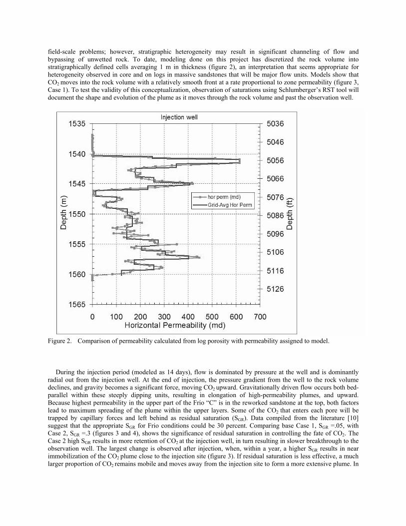
field-scale problems; however, stratigraphic heterogeneity may result in significant channeling of flow and bypassing of unwetted rock. To date, modeling done on this project has discretized the rock volume into stratigraphically defined cells averaging 1 m in thickness (figure 2), an interpretation that seems appropriate for heterogeneity observed in core and on logs in massive sandstones that will be major flow units. Models show that CO2 moves into the rock volume with a relatively smooth front at a rate proportional to zone permeability (figure 3, Case 1). To test the validity of this conceptualization, observation of saturations using Schlumberger’s RST tool will document the shape and evolution of the plume as it moves through the rock volume and past the observation well.
Figure 2. Comparison of permeability calculated from log porosity with permeability assigned to model.
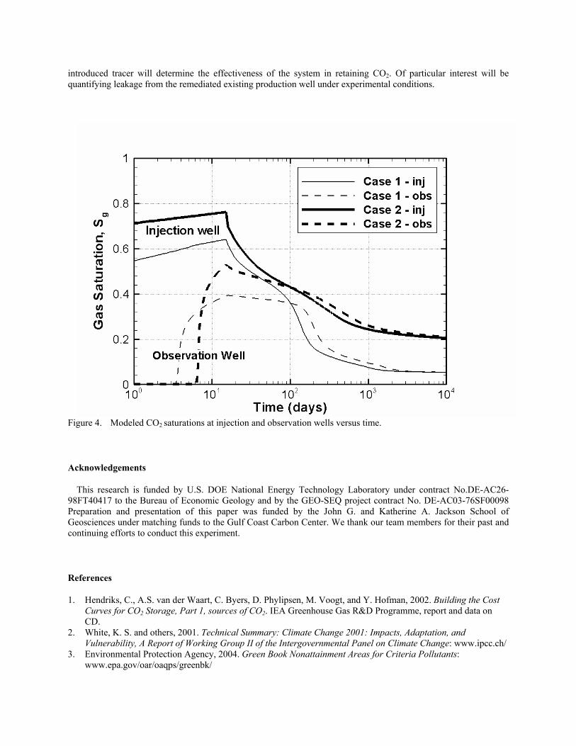
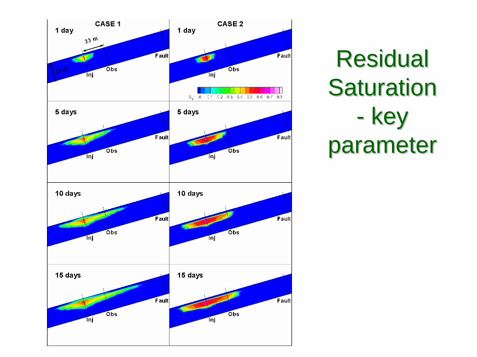
During the injection period (modeled as 14 days), flow is dominated by pressure at the well and is dominantly radial out from the injection well. At the end of injection, the pressure gradient from the well to the rock volume declines, and gravity becomes a significant force, moving CO2 upward. Gravitationally driven flow occurs both bed-parallel within these steeply dipping units, resulting in elongation of high-permeability plumes, and upward. Because highest permeability in the upper part of the Frio “C” is in the reworked sandstone at the top, both factors lead to maximum spreading of the plume within the upper layers. Some of the CO2 that enters each pore will be trapped by capillary forces and left behind as residual saturation (SGR). Data compiled from the literature [10] suggest that the appropriate SGR for Frio conditions could be 30 percent. Comparing base Case 1, SGR =.05, with Case 2, SGR =.3 (figures 3 and 4), shows the significance of residual saturation in controlling the fate of CO2. The Case 2 high SGR results in more retention of CO2 at the injection well, in turn resulting in slower breakthrough to the observation well. The largest change is observed after injection, when, within a year, a higher SGR results in near immobilization of the CO2 plume close to the injection site (figure 3). If residual saturation is less effective, a much larger proportion of CO2 remains mobile and moves away from the injection site to form a more extensive plume. In
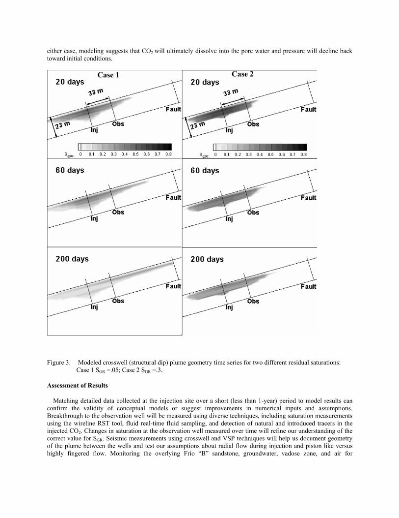
either case, modeling suggests that CO2 will ultimately dissolve into the pore water and pressure will decline back toward initial conditions.
Figure 3. Modeled crosswell (structural dip) plume geometry time series for two different residual saturations: Case 1 SGR =.05; Case 2 SGR =.3.
Assessment of Results
Matching detailed data collected at the injection site over a short (less than 1-year) period to model results can confirm the validity of conceptual models or suggest improvements in numerical inputs and assumptions. Breakthrough to the observation well will be measured using diverse techniques, including saturation measurements using the wireline RST tool, fluid real-time fluid sampling, and detection of natural and introduced tracers in the injected CO2. Changes in saturation at the observation well measured over time will refine our understanding of the correct value for SGR. Seismic measurements using crosswell and VSP techniques will help us document geometry of the plume between the wells and test our assumptions about radial flow during injection and piston like versus highly fingered flow. Monitoring the overlying Frio “B” sandstone, groundwater, vadose zone, and air for
introduced tracer will determine the effectiveness of the system in retaining CO2. Of particular interest will be quantifying leakage from the remediated existing production well under experimental conditions.
Figure 4. Modeled CO2 saturations at injection and observation wells versus time.
Acknowledgements
This research is funded by U.S. DOE National Energy Technology Laboratory under contract No.DE-AC26-98FT40417 to the Bureau of Economic Geology and by the GEO-SEQ project contract No. DE-AC03-76SF00098 Preparation and presentation of this paper was funded by the John G. and Katherine A. Jackson School of Geosciences under matching funds to the Gulf Coast Carbon Center. We thank our team members for their past and continuing efforts to conduct this experiment.
References
1. Hendriks, C., A.S. van der Waart, C. Byers, D. Phylipsen, M. Voogt, and Y. Hofman, 2002. Building the Cost Curves for CO2 Storage, Part 1, sources of CO2. IEA Greenhouse Gas R&D Programme, report and data on CD.
2. White, K. S. and others, 2001. Technical Summary: Climate Change 2001: Impacts, Adaptation, and Vulnerability, A Report of Working Group II of the Intergovernmental Panel on Climate Change: www.ipcc.ch/
3. Environmental Protection Agency, 2004. Green Book Nonattainment Areas for Criteria Pollutants: www.epa.gov/oar/oaqps/greenbk/

4. Hovorka, S.D., and Knox, P.R. 2003. “Frio Brine Sequestration Pilot in the Texas Gulf Coast,” in Greenhouse Gas Control Technologies, Vol. 1, Eds. J. Gale and Y. Kaya, (Amsterdam, Elsevier Science Ltd.) 583-586.
5. Hovorka, S.D. and others 2004. Report to the Texas Commission on Environmental Quality to Accompany a Class V Application for an Experimental Technology Pilot Injection Well: Frio Pilot in CO2 Sequestration in Brine-Bearing Sandstones: www.beg.utexas.edu/environqlty/co2seq/pubs_presentations/friopilotapplication.pdf.
6. Knox, P.R., J.G. Paine, and S.D. Hovorka, 2003. Environmental Assessment: Optimal Geological Environments for Carbon Dioxide Disposal in Brine Formations (Saline Aquifers) in the United States—Pilot Experiment in the Frio Formation, Houston Area: www.beg.utexas.edu/environqlty/co2seq/pubs_presentations/Frio_draftea4_03.pdf.
7. Pruess, K., C. Oldenburg, and G. Moridis, 1999, TOUGH2 User’s Guide, Version 2.0 (Berkeley, CA, Lawrence Berkeley National Laboratory) Report LBNL-43134.
8. Pruess, K. and J. Garcia. 2002. Multiphase Flow Dynamics during CO2 Injection into Saline Aquifers. Environmental Geology 42:282-295.
9. Pruess, K. and others, 2001. Numerical Modeling of Aquifer Disposal of CO2. SPE 66537. www-esd.lbl.gov/GEOSEQ/pdf/pruess_spe66537.pdf
10. Holtz, M.H., 2002. Optimization of CO2 Sequestered as a Residual Phase in Brine-Saturated Formations. http://www.beg.utexas.edu/environqlty/co2seq/pubs_presentations/holtz_poster.pdf

Susan Hovorka *Christine Doughty**
and Mark Holtz*
*Bureau of Economic Geology,Jackson School of Geosciences
University of Texas at Austin** Lawrence Berkeley National Lab
TESTING EFFICIENCY OF TESTING EFFICIENCY OF STORAGE IN THE STORAGE IN THE
SUBSURFACE: FRIO BRINE SUBSURFACE: FRIO BRINE PILOT EXPERIMENTPILOT EXPERIMENT
Texas Gulf CoastTexas Gulf Coast
Frio Brine Pilot Research TeamFrio Brine Pilot Research Team
• Funded by US DOE National Energy Technology Lab: Karen Cohen/Charles Byrer• Bureau of Economic Geology, Jackson School, The University of Texas at Austin: Susan
Hovorka, Mark Holtz, Shinichi Sakurai, Seay Nance, Joseph Yeh, Paul Knox, Khaled Faoud• Lawrence Berkeley National Lab, (Geo-Seq): Larry Myer, Tom Daley, Barry Freifeld, Rob Trautz,
Christine Doughty, Sally Benson, Karsten Pruess, Curt Oldenburg, Jennifer Lewicki, Ernie Major, Mike Hoversten, Mac Kennedy; Don Lippert
• Oak Ridge National Lab: Dave Cole, Tommy Phelps • Lawrence Livermore National Lab: Kevin Knauss, Jim Johnson • Alberta Research Council: Bill Gunter, John Robinson• Texas American Resources: Don Charbula, David Hargiss• Sandia Technologies: Dan Collins, “Spud” Miller, David Freeman; Phil Papadeau • BP: Charles Christopher, Mike Chambers • Schlumberger: T. S. Ramakrishna and others • SEQUIRE – National Energy Technology Lab: Curt White, Rod Diehl, Grant Bromhall, Brian
Stratizar, Art Wells • University of West Virginia: Henry Rausch• USGS: Yousif Kharaka, Bill Evans, Evangelos Kakauros, Jim Thorsen• Praxair: Joe Shine, Dan Dalton• Australian CO2CRC (CSRIO): Kevin Dodds• Core Labs: Paul Martin and others
•Demonstrate that CO2 can be injected into a brine formation without adverse health, safety, or environmental effects
•Determine the subsurface distribution of injected CO2 using a diverse monitoring technologies
•Demonstrate validity of conceptual and numerical models
•Develop experience necessary for success of large-scale CO2injection experiments
How can we demonstrate that geologic How can we demonstrate that geologic storage is an effective method of storage is an effective method of reducing emissions of COreducing emissions of CO22 to the to the
atmosphere?atmosphere?
#
#
#
#
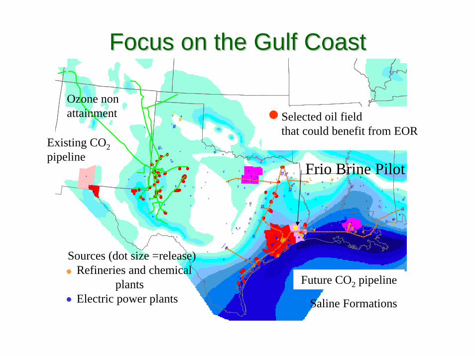
Saline Formations
Focus on the Gulf CoastFocus on the Gulf Coast#
#
#
#
#
#
#
#
Ozone nonattainment
#
#
#
#
##
#
#
##
##
##
#
#
#
###
# #
#
##
#
##
#
#
#
#
#
#
#
#
###
#
##
#
## #
#
# #
#
# ##
#
## #
#
#
##
#
#
#
#
##
##
##
#
#
###
#
#
#####
##
##
#
#
#
#
#
#
# ##
#
#
#
#
# #
#
#
#
# #
#
#
#
#
##
#
##
##
#
## ##
#
#
#
#
###
#
####
##
#
#
##
##
##
# #
##
#
# #
#
#
#
#
#
##
#
##
#
# #
#
#
#
#
#
#
#
#
#
##
# ##
#
#
#
#
#
##
#
#
#
#
#
#
#
#
#
#
##
#
###
#
#
#
#
#
#
#
#
#
#
#
##
#
#
#
#
###
#
#
##
##
# #
#
#
#
#
#### ###
#
#
##
#
#
#
#
#
#
#
#
#
##
#
#
#
#
#
#
#
#
#
#
#
#
#
#
#
#
#
#
#
#
#
#
#
#
#
#
#
#
##
# #
#
#
#
#
#
#
#
#
#
#
#
#
#
#
#
#
#
#
#
#
#
#
#
#
#
#
#
#
##
#
#
#
##
#
#
#
#
#
#
#
#
#
#
#
#
#
#
#
#
#
#
##
#
##
#
##
#
##
##
##
##
##
###
# #
#
#
#
####
#
#
#
##
##
#
#
#
##
#
#
#
##
#
## # ##
#
## #
#
#
#
#
# #
## #
#
#
#
#
#
##
##
#
#
##
#
#
#
#
#
#
#
#
#
Sources (dot size =release)Refineries and chemical
plantsElectric power plants
#
#
#
#
Selected oil fieldthat could benefit from EOR
#
#
#
#
Existing CO2pipeline
#
#
#
#
Future CO2 pipeline
Frio Brine Pilot
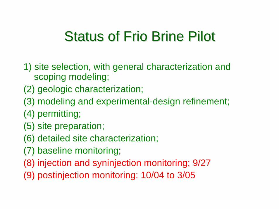
Status of Frio Brine PilotStatus of Frio Brine Pilot
1) site selection, with general characterization and scoping modeling;
(2) geologic characterization; (3) modeling and experimental-design refinement; (4) permitting; (5) site preparation; (6) detailed site characterization; (7) baseline monitoring; (8) injection and syninjection monitoring; 9/27(9) postinjection monitoring: 10/04 to 3/05

Site SettingSite Setting
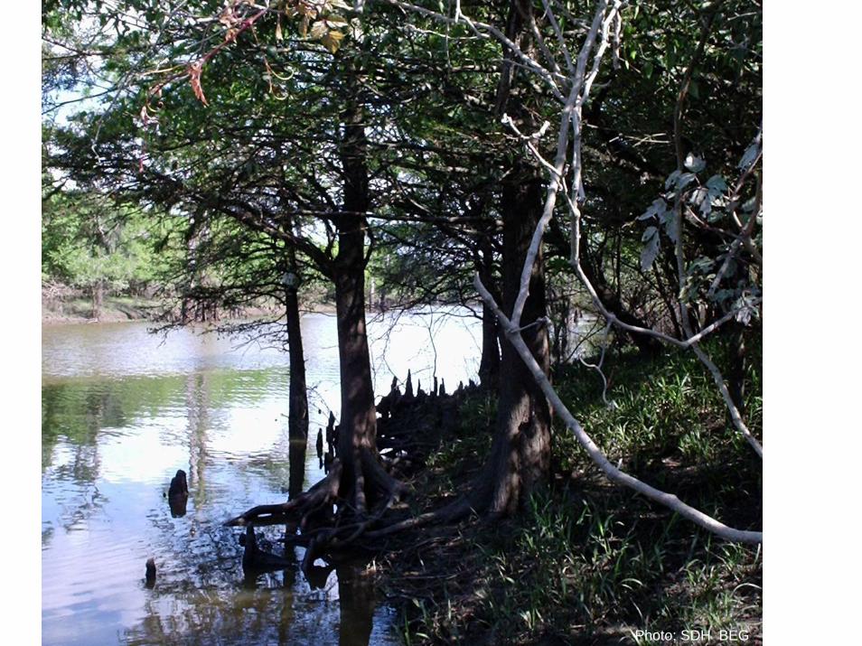
Photo: SDH BEG

Observation WellInjection Well
Frio Brine PilotFrio Brine Pilot
• Injection interval: 24-m-thick, mineralogically complex Oligocene reworked fluvial sandstone, porosity 24%, Permeability 2-3 Darcys
• Seals − numerous thick shales, small fault block
• Depth 1,500 m• Brine-rock system, no
hydrocarbons• 190 bar
Injection interval
Oil production
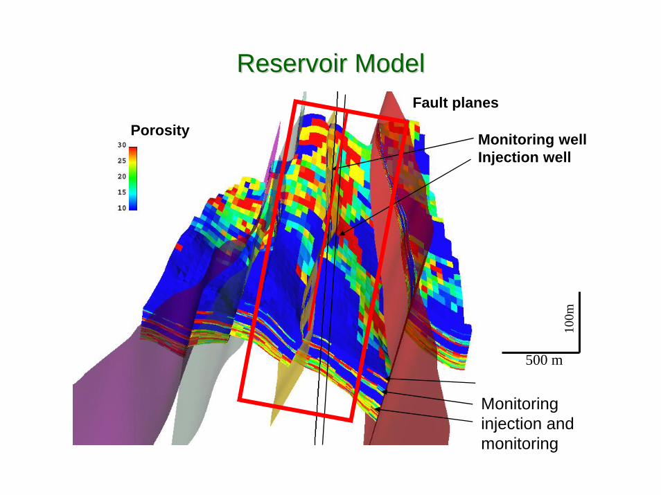
Porosity
Fault planes
Monitoringinjection and monitoring
Monitoring wellInjection well
Reservoir ModelReservoir Model
500 m
100m

Core has been slabbed Core has been slabbed while still frozen, and while still frozen, and
samples cut for samples cut for petrophysical, petrophysical,
petrographic, and petrographic, and geochemical analysisgeochemical analysis
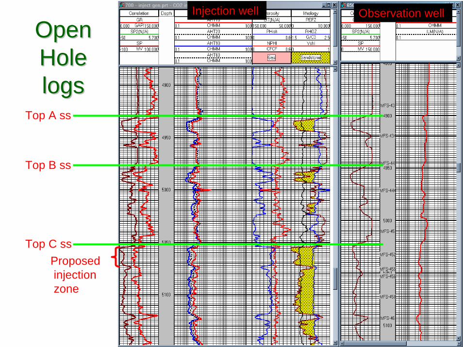
Open Open Hole Hole logslogs
Injection well Observation well
Top A ss
Top B ss
Top C ssProposedinjectionzone

Log Permeability Calibrated with Plug Log Permeability Calibrated with Plug PermeabilityPermeability
Log Interpretation, Shinichi Sakurai
Injection Zone
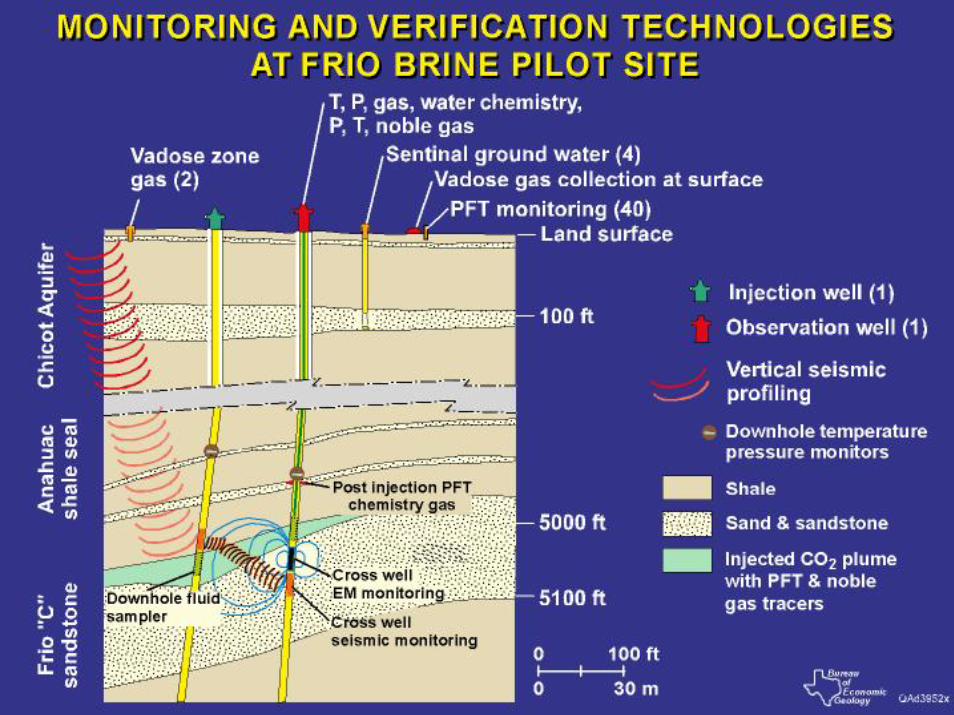

Frio PreFrio Pre--Injection GeophysicsInjection GeophysicsVSP- Designed for monitoringand imaging
- 8 Explosive Shot Points(100 – 1500 m offsets)
- 80 – 240 3C Sensors(1.5 – 7.5 m spacing)
Cross Well- Designed for monitoring and CO2 saturation estimation
- P and S Seismic and EM- > 75 m coverage @ 1.5 m Spacing
(orbital-vibrator seismic source,3C geophone sensor)
- Dual Frequency E.M.
P-Wave
S-wave
P-Wave
Denser spacing inreservoir interval
Reflection
From Tom Daley, LBNL

How Modeling and Monitoring will Assess COHow Modeling and Monitoring will Assess CO22PerformancePerformance
• Modeling has identified variables which appear to control CO2 injection and post injection migration.
• Measurements made over a short time frame and small distance will confirm the correct value for these variables
• Better conceptualized and calibrated models will be used to develop larger scale longer time frame injections
Residual gas saturation of 5%
Residual gas saturation of 30%
TOUGH2 simulations C. Doughty LBNL
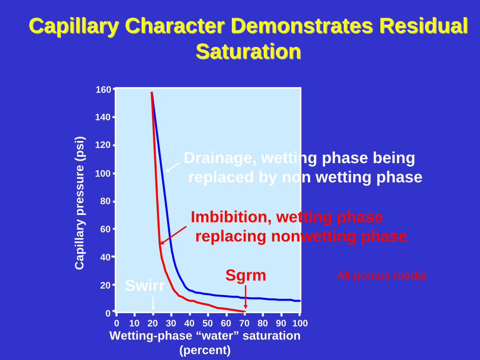
Capillary Character Demonstrates Residual Capillary Character Demonstrates Residual SaturationSaturation
0
20
40
60
80
100
120
140
160
0 10 20 30 40 50 60 70 80 90 100Wetting-phase “water” saturation
(percent)
Cap
illar
y pr
essu
re (p
si)
Drainage, wetting phase beingreplaced by non wetting phase
Imbibition, wetting phasereplacing nonwetting phase
Swirr Sgrm All porous media
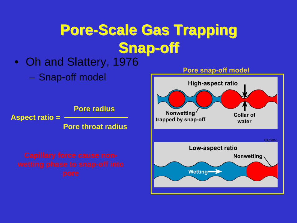
PorePore--Scale Gas TrappingScale Gas TrappingSnapSnap--offoff
• Oh and Slattery, 1976– Snap-off model
Capillary force cause non-wetting phase to snap-off into
pore
Aspect ratio =Pore radius
Pore throat radius
Residual Residual SaturationSaturation
-- key key parameterparameter
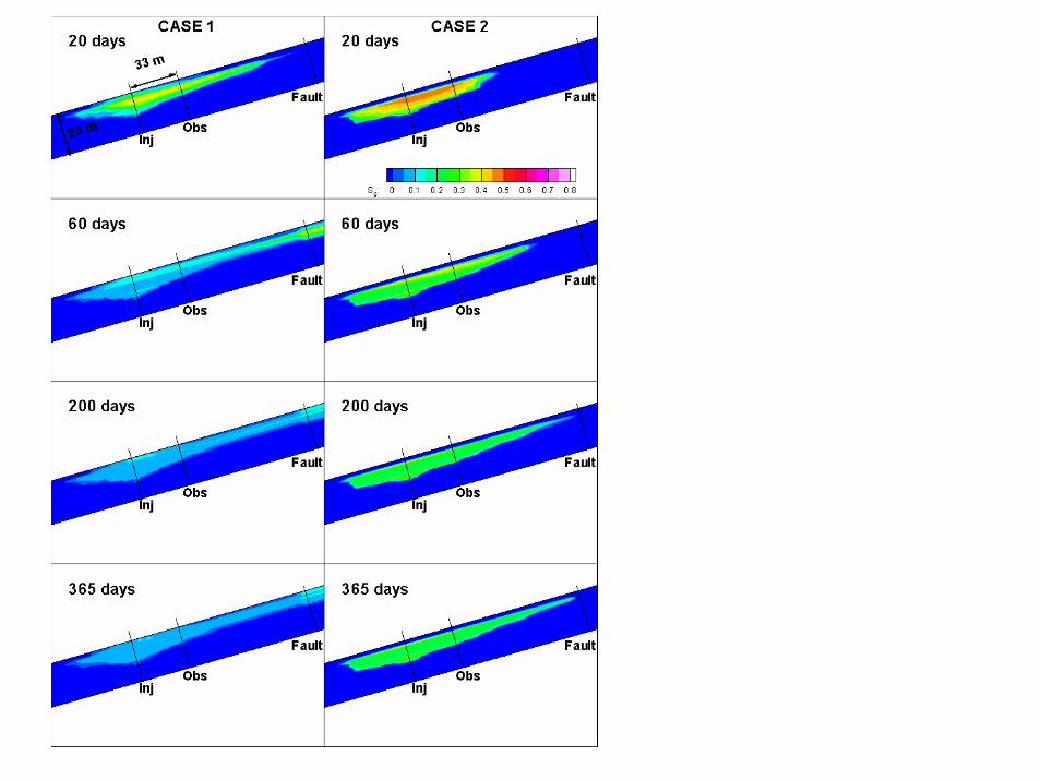

Case 1 Case 2
Impact of Residual Saturation on COImpact of Residual Saturation on CO22DistributionDistribution

Frio Brine Pilot SummaryFrio Brine Pilot Summary
• MMV demonstration in high permeability sandstone
• Comparison of diverse MMV technologies
• Better understanding of CO2 behavior though model matching
• Invitation for participation • Updates: www.gulfcoastcarbon.org


