SUBSURFACE EXPLORATIONS STANDARDSmsa.maryland.gov/megafile/msa/speccol/sc5300/sc... · SUBSURFACE...
36
MARYLAND STATE HIGHWAY ADMINISTRATION STANDARD SPECIFICATIONS FOR SUBSURFACE EXPLORATIONS I Maryland State Highway Administration Standard Specifications for Subsurface Explorations Contact: Freddie J. Baker Maryland State Highway Administration Office of Materials and Technology Field Explorations Division 2323 W. Joppa Road Lutherville, Maryland 21093 (410) 321-3161 Fax (410) 321-3099 SHA Internet: http://www.marylandroads.com/businesswithsha/bizStdsSpecs/desManualStdPub/hardcopyPubInfoOrdering/ omr/omrpub.asp Initial Release: 04/04/01 Revised: 09/23/05
Transcript of SUBSURFACE EXPLORATIONS STANDARDSmsa.maryland.gov/megafile/msa/speccol/sc5300/sc... · SUBSURFACE...
MARYLAND STATE HIGHWAY ADMINISTRATION
STANDARD SPECIFICATIONS FOR SUBSURFACE EXPLORATIONS
I
Maryland State Highway Administration
Standard Specifications for Subsurface Explorations
Contact: Freddie J. Baker
Maryland State Highway Administration Office of Materials and Technology Field Explorations Division 2323 W. Joppa Road Lutherville, Maryland 21093 (410) 321-3161 Fax (410) 321-3099 SHA Internet: http://www.marylandroads.com/businesswithsha/bizStdsSpecs/desManualStdPub/hardcopyPubInfoOrdering/omr/omrpub.asp Initial Release: 04/04/01 Revised: 09/23/05
MARYLAND STATE HIGHWAY ADMINISTRATION
STANDARD SPECIFICATIONS FOR SUBSURFACE EXPLORATIONS
II
TABLE OF CONTENTS SUBSURFACE EXPLORATIONS - GENERAL SPECIFICATIONS Page
GS –1 SCOPE 1 GS-2 GENERAL REQUIREMENTS 1 GS-2.1 Engineer 1 GS-2.2 On-Site Equipment Protection 1 GS-2.3 Maintenance and Control of Traffic 1 GS-2.4 Permits, Utility Clearances and Licenses 2 GS-2.5 Public Convenience 2 GS-2.6 Safety 3 GS-3 RESPONSIBILITY FOR DAMAGE CLAIMS, ETC 4 GS-3.1 Public Liability 4
(1) Contractor's Public Liability and Property Damage 4 Liability Insurance
(2) Contractor's Protective Liability and Property 5
Damage Liability Insurance
GS-4 UNDERGROUND PIPES, UTILITIES AND OTHER OBSTRUCTIONS 5 GS-5 PROTECTION OF SAMPLES AND RECORDS 5 SUBSURFACE EXPLORATIONS TECHNICAL SPECIFICATIONS TS-1 GENERAL 6 TS-2 CONDUCT OF THE WORK 6
TS-2.1 General 6
TS-2.2 Borings in Streets and Paved Areas 6
TS-2.3 Refilling of Holes 6
TS-2.4 Cleaning up 7 TS-3 BORING LOCATIONS AND SAMPLES 7
MARYLAND STATE HIGHWAY ADMINISTRATION
STANDARD SPECIFICATIONS FOR SUBSURFACE EXPLORATIONS
III
TS-4 PROCEDURES FOR MAINTAINING AN OPEN BORE HOLE 7 TS-5 RECORDS AND LOGS 7 TS-6 FINAL DRILLER’S LOG’S 8 TS-7 RETAINAGE OF SAMPLES AND CORES 8 TS-8 STANDARD PENETRATION TEST BORINGS 8
TS-8.1 General 8
TS-8.2 Driving casing 9
TS-8.3 Hollow Stem Augers 9
TS-8.4 Frequency of Sampling 10
TS-8.5 Sampling Procedure 10
TS-8.6 Sampling Devices 10
TS-8.7 Preservation and Identification of Samples 11
TS-8.8 Determination of Running Sand 11
TS-8.9 Ground Water 12
TS-8.10 Removal of Casing or Hollow Stem Augers From Ground 12
TS-8.11 Record Data 12 TS-9 CORE BORINGS 15
TS-9.1 General 15
TS-9.2 Drilling Devices 15
TS-9.3 Maintaining An Open Bore Hole For Casing 16
TS-9.4 Coring Procedure 16
TS-9.5 Preservation and Identification of Cores 16
TS-9.6 Record Data 17 TS-10 SEALING BORE HOLES 17
TS-10.1 Sealing Materials 17
MARYLAND STATE HIGHWAY ADMINISTRATION
STANDARD SPECIFICATIONS FOR SUBSURFACE EXPLORATIONS
IV
TS-10.2 Sealing Procedures 18
TS-11 WELLS/PIEZOMETERS 18
TS-11.1 General 18 TS-11.2 Wellpoints 18 TS-11.3 Shallow Monitoring Wells Installation 19 TS-11.4 Piezometers Installation 19 TS-11.5 Monitoring Ground Water Levels 20
TS-11.6 Piezometers or Shallow Monitoring Wells Abandonment 21 TS-12 INCLINOMETER INSTALLATION 21
TS-12.1 General 21
TS-13 SOIL PERMEABILITY TESTS 22
TS-13.1 General 22 TS-13.2 Testing Procedure 22 TS-13.3 Record Data 24
TS-14 AUGER BORINGS 24
TS-14.1 Boring and Sampling Procedure 24 TS-14.2 Depth of Borings 24 TS-14.3 Frequency of Sampling 25 TS-14.4 Preservation, Identification and Quantity of Samples 25 TS-14.5 Protection of Samples and Records 27 TS-14.6 Visual Description of Samples 27 TS-14.7 Record Data 27
TS-15 PATCHING OF BORE HOLES IN BRIDGE DECKS 28
TS-15.1 Patching Procedure 28
MARYLAND STATE HIGHWAY ADMINISTRATION
STANDARD SPECIFICATIONS FOR SUBSURFACE EXPLORATIONS
V
TS-16 PAVEMENT CORING 28
TS-16.1 Measurement and Payment 29
TS-17 PATCHING PAVEMENT CORE HOLES 29 TS-18 FLAT PLATE DILATOMETER 29 TS-19 PREBORING PRESSUREMETER ( PBPMT) 29 TS-20 VANE SHEAR TESTING 30 TS-21 LABORATORY TESTING OF RECOVERED SOIL SAMPLES 30
MARYLAND STATE HIGHWAY ADMINISTRATION
STANDARD SPECIFICATIONS FOR SUBSURFACE EXPLORATIONS
1
SUBSURFACE EXPLORATIONS
GENERAL SPECIFICATIONS
GS-1 SCOPE The scope of work to be performed under this specification consists of the exploration of subsurface throughout the State of Maryland. The work to be performed by the Contractor consists of the furnishing of all materials, labor, tools, machinery and other equipment, vehicular transportation, and all incidentals necessary and proper for the expeditious completion of these subsurface investigations; all in accordance with these specifications and the Maryland Department Of Transportation/State Highway Administration Specifications entitled "Standard Specifications for Construction & Materials" dated January 2001; and project plans, which will be provided to the Contractor. GS-2 GENERAL REQUIREMENTS GS-2.1 Engineer Wherever in these Specifications and/or other Contract Documents the term Engineer or "MD SHA" is used without further qualification, it shall mean the Maryland State Highway Administration or its representative. GS-2.2 On-Site Equipment Protection When borings or in-situ tests are to be drilled on or adjacent to public highways, private entrances, or walkways or other private properties, it shall be the Contractor's responsibility to adequately, and continuously maintain safety on all portions of the project site. No equipment or material shall be left unattended within 30 feet of a traveled roadway, unless an approved protective barrier is used or an approved work zone traffic control plan is in place. GS-2.3 Maintenance and Control of Traffic
Maintenance of Traffic will be supplied by the Administration when required for a job assignment. Maintenance of Traffic shall be as specified by the Engineer, or the District Traffic Engineer, as required for each individual work site and in accordance with the latest “Manual on Uniform Traffic Control Devices” (MUTCD), the Federal Highway Administration’s “Traffic Control Handbook”, Section 104 of the Specifications, and the SHA Traffic Control plans.
At the direction of the Engineer, work may not be permitted at or near traveled lanes based on
traffic volumes and conditions. The traffic conditions will be determined by the Engineer. In some cases, the period for drilling operations or the Contractor’s work hours may be limited between 9:00 am and 3:00 pm as may be directed by the District Traffic Engineer. Whenever MOT will be required on any work assignment which will result in a different than the usual work start time for the Contractor’s personnel, the Contractor shall adjust to the new start time, which is dictated by the MOT time restrictions.
MARYLAND STATE HIGHWAY ADMINISTRATION
STANDARD SPECIFICATIONS FOR SUBSURFACE EXPLORATIONS
2
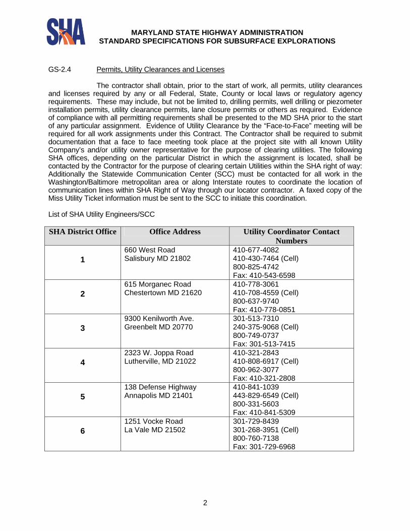
GS-2.4 Permits, Utility Clearances and Licenses The contractor shall obtain, prior to the start of work, all permits, utility clearances and licenses required by any or all Federal, State, County or local laws or regulatory agency requirements. These may include, but not be limited to, drilling permits, well drilling or piezometer installation permits, utility clearance permits, lane closure permits or others as required. Evidence of compliance with all permitting requirements shall be presented to the MD SHA prior to the start of any particular assignment. Evidence of Utility Clearance by the “Face-to-Face” meeting will be required for all work assignments under this Contract. The Contractor shall be required to submit documentation that a face to face meeting took place at the project site with all known Utility Company’s and/or utility owner representative for the purpose of clearing utilities. The following SHA offices, depending on the particular District in which the assignment is located, shall be contacted by the Contractor for the purpose of clearing certain Utilities within the SHA right of way: Additionally the Statewide Communication Center (SCC) must be contacted for all work in the Washington/Baltimore metropolitan area or along Interstate routes to coordinate the location of communication lines within SHA Right of Way through our locator contractor. A faxed copy of the Miss Utility Ticket information must be sent to the SCC to initiate this coordination. List of SHA Utility Engineers/SCC SHA District Office Office Address Utility Coordinator Contact
Numbers
1 660 West Road Salisbury MD 21802
410-677-4082 410-430-7464 (Cell) 800-825-4742 Fax: 410-543-6598
2
615 Morganec Road Chestertown MD 21620
410-778-3061 410-708-4559 (Cell) 800-637-9740 Fax: 410-778-0851
3
9300 Kenilworth Ave. Greenbelt MD 20770
301-513-7310 240-375-9068 (Cell) 800-749-0737 Fax: 301-513-7415
4
2323 W. Joppa Road Lutherville, MD 21022
410-321-2843 410-808-6917 (Cell) 800-962-3077 Fax: 410-321-2808
5
138 Defense Highway Annapolis MD 21401
410-841-1039 443-829-6549 (Cell) 800-331-5603 Fax: 410-841-5309
6
1251 Vocke Road La Vale MD 21502
301-729-8439 301-268-3951 (Cell) 800-760-7138 Fax: 301-729-6968
MARYLAND STATE HIGHWAY ADMINISTRATION
STANDARD SPECIFICATIONS FOR SUBSURFACE EXPLORATIONS
3
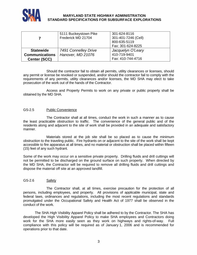
7
5111 Buckeystown Pike Frederick MD 21704
301-624-8116 301-401-7246 (Cell) 800-635-5119 Fax: 301-624-8225
Statewide Communications
Center (SCC)
7491 Connelley Drive Hanover, MD 21076
Jacquelyn O'Leary 410-719-9401 Fax: 410-744-4716
Should the contractor fail to obtain all permits, utility clearances or licenses, should any permit or license be revoked or suspended, and/or should the contractor fail to comply with the requirements of any permits, utility clearances and/or licenses, the MD SHA may elect to take prosecution of the work out of the hands of the Contractor. Access and Property Permits to work on any private or public property shall be obtained by the MD SHA. GS-2.5 Public Convenience The Contractor shall at all times, conduct the work in such a manner as to cause the least practicable obstruction to traffic. The convenience of the general public and of the residents along and adjacent to the site of work shall be provided in an adequate and satisfactory manner. Materials stored at the job site shall be so placed as to cause the minimum obstruction to the traveling public. Fire hydrants on or adjacent to the site of the work shall be kept accessible to fire apparatus at all times, and no material or obstruction shall be placed within fifteen (15) feet of any such hydrant. Some of the work may occur on a sensitive private property. Drilling fluids and drill cuttings will not be permitted to be discharged on the ground surface on such property. When directed by the MD SHA, the Contractor will be required to remove all drilling fluids and drill cuttings and dispose the material off site at an approved landfill. GS-2.6 Safety
The Contractor shall, at all times, exercise precaution for the protection of all persons, including employees, and property. All provisions of applicable municipal, state and federal laws, ordinances and regulations, including the most recent regulations and standards promulgated under the Occupational Safety and Health Act of 1977 shall be observed in the conduct of the work.
The SHA High Visibility Apparel Policy shall be adhered to by the Contractor. The SHA has
developed the High Visibility Apparel Policy to make SHA employees and Contractors doing work for the SHA more easily seen as they work on highways and rights-of-way. Full compliance with this policy will be required as of January 1, 2006 and is recommended for operations prior to that date.
MARYLAND STATE HIGHWAY ADMINISTRATION
STANDARD SPECIFICATIONS FOR SUBSURFACE EXPLORATIONS
4
The High Visibility Apparel policy adopts the Headwear standard from the American
National Standards Institute/International Safety and Equipment Association (ANSI/ISEA 107-2004). This standard provides guidelines for visibility protection for all persons who must perform activities on SHA highways and rights-of-way.
The standard consists of three class levels; a minimum of a Class 2 ANSI/ISEA 107-2004 will be required for all persons who work on SHA highways and rights-of-way. The apparel will be fluorescent yellow-green background and will be the outermost garment worn. If any construction operation, practice, or condition is deemed by the MD SHA to be unsafe, the Contractor, when notified in writing by the MD SHA, shall take such corrective action as shall be appropriate in the circumstances, or as shall be directed by the MD SHA. However, when in the opinion of the MD SHA, any operation, practice or condition endangers persons, including employees or property, it shall be summarily discontinued, and adequate remedial action taken by the Contractor before the affected part of the work is resumed. Nothing in the foregoing paragraphs shall be construed as relieving the Contractor from full responsibility for safe prosecution of the work at all times. GS-3 RESPONSIBILITY FOR DAMAGE CLAIMS, ETC The Contractor shall indemnify and save harmless the MD SHA and any representative thereof, from all suites, actions, or claims of any character brought on account of any injuries or damages sustained by any person or property in consequence of any neglect in safeguarding the work, or on account of any act or omission by the said Contractor, or on account of any claims or amounts recovered from any infringement of patent, trademark, or copyright, or from any claims or amounts arising or recovered under the Workmen's Compensation law, or any other law, by-law, ordinances, order or decree. The Contractor shall be responsible for all damage or injury to property of any character during the prosecution of the work resulting from any act, omission, neglect, or misconduct, the manner or method of executing said work satisfactorily, or due to the non-execution of the said work, and said responsibility shall continue until the work approved by MD SHA shall have been completed and accepted. GS-3.1 Public Liability Before any work under this contract is commenced, the Contractor shall, in addition to any other forms of insurance or bonds required under the terms of the contract and specifications, procure and maintain during the life of the contract the following types of insurance in the amounts set forth. (1) Contractor's Public Liability and Property Damage Liability Insurance The Contractor shall furnish evidence satisfactory to the MD SHA that, with respect to the operations he performs, he carries regular Contractor's Public Liability Insurance providing for a limit of not less than One Million Dollars ($1,000,000.00) liability for all damages arising out of bodily injuries to or death of one person, and a total (or aggregate) limit of One Million Dollars ($1,000,000.00) liability for all damages arising out of bodily injuries to or death of two or more persons in any one accident; and regular Contractor's Property Damage Liability Insurance
MARYLAND STATE HIGHWAY ADMINISTRATION
STANDARD SPECIFICATIONS FOR SUBSURFACE EXPLORATIONS
5
providing for a limit of not less than One Million Dollars ($1,000,000.00) liability for all damages arising out of injury to or destruction of property in any one accident, and a total (or aggregate) limit of One Million Dollars ($1,000,000.00) liability for all damages arising out of injury to or destruction of property during the life of the contract. A copy of the policy for such insurance in the name of the Contractor shall be delivered to the MD SHA. (2) Contractor's Protective Liability and Property Damage Liability Insurance If any part of the work is to be performed by a subcontractor, the Contractor shall furnish evidence satisfactory to the MD SHA that, with respect to the operations performed for him by subcontractors, he carries in his own behalf regular Contractor's Protective Public Liability Insurance providing for a limit of not less than One Million Dollars ($1,000,000.00) liability for all damages arising out of bodily injuries to or death of one person, and a total (or aggregate) limit of One Million Dollars ($1,000,000.00) liability for all damages arising out of bodily injuries to or death of two or more persons in any one accident; and regular Contractor's Protective Property Damage Liability Insurance providing for a limit of not less than One Million Dollars ($1,000,000.00) liability for all damages arising out of injury to or destruction of property in any one accident, and a total (or aggregate) limit of One Million Dollars ($1,000,000.00) liability for all damages arising out of injury to or destruction of property during the life of the contract. A copy of the policy for such insurance in the name of the Contractor shall be delivered to the MD SHA. GS-4 UNDERGROUND PIPES, UTILITIES AND OTHER OBSTRUCTIONS Plans may be provided by MD SHA showing the locations of various underground pipes, utilities, and other structures in the general work area. This information was obtained from the most reliable sources available; however, the MD SHA makes no warranty, expressed or implied, as to the accuracy, type or number of underground pipes, utilities or obstructions within the project site. It shall be the responsibility of the Contractor to verify or determine the locations of all underground pipes, utilities and structures in the immediate vicinity of his operations, and to exercise all due precautions to prevent damage to all underground pipes, utilities and structures. Should any damage to such pipes, utilities or structures occur as a result of the Contractor's operations, the Contractor shall, at his own cost and expense, restore such utilities or structures to a condition equal to that which existed before the damage occurred. GS-5 PROTECTION OF SAMPLES AND RECORDS The Contractor shall provide a location for the storage of samples and records so as to protect them against theft, loss, freezing, or damage. Storage and preservation of all samples and records prior to completion of the work shall be the responsibility of the Contractor. All samples and records shall be kept for review by MD SHA until the subsurface information for a specific project is presented and found acceptable to MD SHA.
MARYLAND STATE HIGHWAY ADMINISTRATION
STANDARD SPECIFICATIONS FOR SUBSURFACE EXPLORATIONS
6
SUBSURFACE EXPLORATIONS
TECHNICAL SPECIFICATIONS TS-1 GENERAL
The Contractor shall so conduct his work as to accurately determine the nature and depth of each stratum of material encountered and to preserve the natural properties of the materials for future laboratory testing. All methods and equipment shall be as specified herein and shall be subject to the approval of Maryland State Highway Administration and hereinafter referred to as the MD SHA. TS-2 CONDUCT OF THE WORK TS-2.1 General
The Contractor shall perform such clearing and grubbing as may be necessary to provide access and working space at the site or sites of the work; and do all other work which may be necessary to move his equipment around or between the test boring locations. It shall be the contractor's responsibility to perform any clearing or grubbing in accordance with any local, municipal, state, or federal laws, and property owner(s) requirements. All applicable sediment and erosion control regulations, tree protection regulations and all other environmental rules and regulations, affecting the prosecution of the work, shall be strictly adhered by the contractor. TS-2.2 Borings in Streets and Paved Areas
Where borings are to be drilled in sidewalks, streets or other paved areas, the area of paving damaged shall be kept to the minimum required for satisfactory completion of the work. All damaged paving shall be repaired or replaced in kind as soon as practicable and to the satisfaction of the MD SHA. TS-2.3 Refilling of Holes
Upon the satisfactory completion of each boring, the measurement of the zero hour and 24 hour groundwater level as well as the bottom depth of the hole at each reading, and the acceptance thereof by the MD SHA, the Contractor shall immediately refill the hole with the drill cuttings. If required, or as directed by the MD SHA, sealing of the hole shall be performed in accordance with the requirements of ARTICLE TS-10 "SEALING BORE HOLES." TS-2.4 Cleaning up
Upon completion of the work, the Contractor shall promptly remove all of his equipment, including all markers, ranges, and stakes placed by him, and shall leave the site in a clean and presentable condition, satisfactory to the MD SHA and the property owners involved.
MARYLAND STATE HIGHWAY ADMINISTRATION
STANDARD SPECIFICATIONS FOR SUBSURFACE EXPLORATIONS
7
TS-3 BORING LOCATIONS AND SAMPLES
The MD SHA will designate, by means of stakes or other marks, the locations of all borings and will establish the existing ground elevation at each boring location.
The Contractor shall not proceed with any boring until the location has been marked in the field by the MD SHA, nor shall he proceed until he has determined the location of all underground utilities and structures in the vicinity of the boring. Should the Contractor determine that a conflict exists between a proposed boring and an existing utility he shall immediately inform the MD SHA, who will then establish a new boring location. The designation of boring locations by the MD SHA shall not in any way relieve the Contractor of his responsibility for damage to underground pipes, utilities or structures.
During the progress of the work, the MD SHA will specify the criteria to which each boring shall be drilled in order that the character of the material at desired elevations or depths can be determined or verified. TS-4 PROCEDURES FOR MAINTAINING AN OPEN BORE HOLE An open bore hole shall be maintained at all times through the use of casing, hollow stem augers or drilling mud. All casing shall be extra-heavy steel or black wrought iron pipe not less than 3-1/2 inch nominal inside diameter. The Contractor may, at his option, utilize flush joint casing instead of conventional pipe casing. Hollow stem augers, of the required diameter, may be utilized in place of driven casing. The use of drilling mud may be permitted provided that the bore hole remains open to the full depth at all times. If drilling mud is used, the MD SHA reserves the right to specify an organic self destroying drilling fluid additive in place of bentonite or other inorganic clay so that accurate ground water measurements can be made in the bore hole. TS-5 RECORDS AND LOGS
The Contractor shall record on standardized boring log forms provided by the MD SHA, such portions of the several categories of data outlined hereinafter as are deemed by the MD SHA to be relevant to the type of boring work accomplished in each case. In addition, each and every boring log shall record the following information:
(1) Title of project and designation of section thereof.
(2) Date of starting and completing borings.
(3) Boring number, (to conform to number assigned on the plans or as furnished by the MD SHA).
(4) Names of the Contractor, Inspector and drilling crew.
(5) Location of site by name, and/or survey station and offset, if any, right or
left of centerline or provide Maryland grid coordinates as measured by a
MARYLAND STATE HIGHWAY ADMINISTRATION
STANDARD SPECIFICATIONS FOR SUBSURFACE EXPLORATIONS
8
GPS measuring device approved by the MD SHA or supplied by the MD SHA.
(6) Ground elevation at boring, as furnished by the MD SHA. (7) Relocated boring’s new Station and the corresponding elevation and
offset and reason for the relocation.
(8) Type and size of drilling equipment used to drill the hole, including make, model and type of hammer.
(9) Procedure used for maintaining an open bore hole. If drilling mud is used,
the type of material used to form the mud.
(10) Depth to top of ground water if present, measured as provided in Article TS-8.9 "Ground Water."
TS-6 FINAL DRILLER’S LOG’S
The final driller’s log shall be submitted with the Geotechnical report for the project to MD SHA within 10 days after completion. TS-7 RETAINAGE OF SAMPLES AND CORES
If upon reviewing the geotechnical report for a specific project,the MD SHA may elect to review testing samples and or cores. All samples and cores, suitably packed and identified as herein specified, shall be delivered to the Maryland State Highway Administration, Field Explorations Division, 2323 W. Joppa Road, Lutherville, Maryland 21093, or other location as may be specified, within 15 days of a request.
All soil samples shall be protected during handling, storage and shipment, from vibration, freezing, and excessive heat.
Sample Jar Lids are to be labeled with the MD SHA Project Identification, Boring
Number, Sample Number and Blow Count. Sample Jar Boxes shall be labeled with the MD SHA Project Identification,
Project Description, Boring Numbers and Sample Numbers. If Sample is complete or continued in the next box, that box shall also be labeled as complete or continued. TS-8 STANDARD PENETRATION TEST BORINGS TS-8.1 General
Standard penetration test borings through soil, utilizing the procedures for maintaining an open bore hole specified in Article TS-4, will be required for subsurface exploration at the locations indicated on the plans and/or as directed by the MD SHA. In general, the selection of the procedure to be used for maintaining an open bore hole will be selected and approved by the MD SHA. The MD SHA reserves the right, however, to change the procedure to be used for maintaining an open bore hole if the procedure being used by the
MARYLAND STATE HIGHWAY ADMINISTRATION
STANDARD SPECIFICATIONS FOR SUBSURFACE EXPLORATIONS
9
Contractor fails to maintain an open hole, results in the recovery of unsuitable or unrepresentative samples or is otherwise not satisfactory. TS-8.2 Driving casing
If casing is used to maintain an open bore hole, it shall be sunk vertically through earth and other materials, including boulders, to such depth below the ground surface as is, in the opinion of the MD SHA, consistent with good practice for conditions encountered. The casing shall be driven without the use of water unless the MD SHA specifically authorizes simultaneous washing and driving; in which case, the boring log shall record the depths between which such practice was followed. A continuous record shall be kept of the number of hammer blows per foot of penetration required in driving the casing. To maintain casing penetration data on a comparative basis, the same weight and fall of casing hammer shall be used for driving casings by all drilling rigs used on this work.
Should a boulder or a stratum of rock with soil beneath be encountered before the required depth of boring has been attained, the Contractor will be required to core drill through the boulder or rock stratum, case the hole, and extend the casing as hereinafter specified in Article TS-9 "Core Borings." Payment for such core drilling will be made at the unit price per linear foot bid in the "Bid or Proposal" for core borings of the size specified by the MD SHA for the particular hole being drilled, provided that the boulder or rock stratum exceeds one (1) foot in thickness.
Blasting with small explosive charges to facilitate penetration of boulders and other obstructions will be not be permitted.
Between the depth intervals, as hereinafter specified, at which sampling is to be accomplished, loose material within the casing shall be removed by the usual wash pipe method or by other suitable means. In no case will the use of bottom discharge fishtail bits be permitted; however, side discharge fishtail bits may be used. The process of jetting through an open-tube sampler and then sampling when the desired depth is reached will not be permitted. TS-8.3 Hollow Stem Augers
If hollow stem augers are used to maintain an open bore hole, the procedure to be used shall be as follows: The augers, with bit attached to the bottom section, shall be advanced by rotating the augers while a downward force is applied to the top section of auger until the depth is reached at which sampling is to be accomplished. When augering between samples, a center plug or drag bit assembly shall be in place to prevent loose material from entering the hollow stem auger. This assembly shall be held in place by a cap and drill rod connecting the auger and assembly to the rotating spindle on the drill rig. The hollow stem augers shall meet the requirements of Acker Model 330359-0 or approved equal,
Upon reaching the depth at which a soil sample is to be obtained, the center plug and drag bit assembly shall be removed to permit lowering of the soil sampling device or core barrel through the hollow stem auger.
Should a boulder or a stratum of rock with soil beneath be encountered before the required depth of boring has been attained, the Contractor will be required to core drill through the boulder or stratum of rock and obtain soil samples of the material beneath. The Contractor shall be responsible for maintaining an open hole through the material that lies below
MARYLAND STATE HIGHWAY ADMINISTRATION
STANDARD SPECIFICATIONS FOR SUBSURFACE EXPLORATIONS
10
the depth interval in which rock coring was performed. If this cannot be accomplished by advancing the hollow stem augers, the Contractor shall use casing or drilling mud, altering his drilling procedures as required to advance the boring to the depth required by the MD SHA.
TS-8.4 Frequency of Sampling
At every change in the character of the material, and at intervals not to exceed five (5) feet, advancement of the hole shall be stopped, all loose material shall be removed from the hole, and a sample of the soil shall be procured as hereinafter specified. The five (5) foot sample interval shall be measured from the top of the first sample to the top of the second sample. The MD SHA reserves the right to require the procurement of additional samples at intermediate depths when, in his opinion, such additional sampling is necessary for proper analysis of subsurface conditions. TS-8.5 Sampling Procedure
The sampling device shall be driven until either 18 inches have been penetrated or 50 blows have been applied with penetration of six (6) inches or less. The number of blows required to effect each six (6) inches of penetration or fraction thereof shall be recorded. The first six (6) inch penetration is considered to be a seating drive. The number of blows required for the second and third six (6) inches of penetration added together is considered the penetration resistance, N. If the sampler is driven less than 18 inches, the penetration resistance is the number of blows required for the last one (1) foot of penetration. The sample so obtained shall be representative of the material from which it is taken, and shall be in an unwashed condition. Samples recovered from wash water, commonly termed "wash samples" will be unacceptable. After the recovered sample has been removed from the sampling device, the sampling device shall be thoroughly washed to prevent contamination of the next sample. The split barrel soil sampler shall not be driven more than 18 inches.
To facilitate comparison of the resistance to penetration of the various strata, the sampling device shall always be driven with the same weight and fall of drop hammer, which hammer shall consist of a weight of one hundred and forty (140) pounds freely falling through a vertical distance of thirty (30) inches. The driving of the split barrel sampler will be accomplished using a fully automatic trip hammer. The use of manila or wire rope to raise the hammer will be permitted only when using skid rig or tri-pod drill equipment. Exceptions may be granted upon request. The sampling hammer need not necessarily have the same weight and fall as the casing hammer. To prevent whipping of the drill rod under the impact of the drop hammer, the drill rod will have a stiffness equal to or greater than "A" rod which has an outside diameter of 1-5/8 inches and an inside diameter of 1-1/8 inches. Penetration and sampling data shall be recorded as herein specified.
Sampling of soil by the above procedure shall be continued until a required depth is achieved or until refusal, defined as 50 blows or more per inch or less of penetration, is obtained. If further advancement of the hole is required, rock coring or Denison sampling will be employed. TS-8.6 Sampling Devices
MARYLAND STATE HIGHWAY ADMINISTRATION
STANDARD SPECIFICATIONS FOR SUBSURFACE EXPLORATIONS
11
All sampling devices used by the Contractor shall have prior approval of the MD SHA. The split barrel sampler shall be Acker Part 22017-2, or approved equal, and shall be 2.0 inches O.D. and 1.5 inches I.D. The sampler shall be in conformance with AASHTO T206.
Sample retainers shall be used with the sampler when necessary to avoid loss of the sample. In cases where the material encountered is so cohesionless that the standard sampler fails to recover a sample on the second trial, a flapper valve, or a sand trap, or other approved device shall be used to recover a sample. The use of such a device shall be noted on the boring log. TS-8.7 Preservation and Identification of Samples
A representative portion of each sample obtained with the standard split-barrel
sampler shall be removed with as little disturbance as practicable, and immediately placed in a suitable, tightly capped, sample jar to be provided by the Contractor. These jars shall be of clear glass; shall have a large mouth, suitable gasket seal, and screw top; and shall be about sixteen (16) ounces in volume, and three and one half inches (3-½) inches at the minimum opening. Each sample jar shall be clearly and permanently labeled to show the project and section, the number of the test boring and station location, the elevation or depth at which the sample was taken, the number of blows of the sampler, and the sample number.
The Contractor shall pack all glass jar samples in containers acceptable to the
MD SHA, and of sufficient durability to withstand handling without breakage of the sample jars. On the top and one end of each container, the Contractor shall neatly and legibly paint or stencil, using waterproof paint, the following identifying data: title of project and designation of section thereof; MD SHA Charge Number; location of site by name and/or survey station; boring numbers; and name of Contractor; or as required or directed by the MD SHA. Use of a label, approved by the MD SHA, is also acceptable. The description of soils encountered shall be made by the driller in the field for use on the preliminary driller's log. On the final boring log, the description and identification of the boring data shall be furnished by the Contractor’s Certified Driller or Soils Engineer/Geologist. Should the MD SHA indicate that the soils description and identification on the final boring logs will be performed by another party rather than the Contractor, then additional jar samples of the type specified herein shall be required. TS-8.8 Determination of Running Sand
Any time that sand, coarse or fine, is encountered, the MD SHA may order that the following test be made to determine if the water content and the pressure upon the material is sufficient to cause it to run when unconfined.
Upon encountering sand, a sample of the material shall be obtained by the method previously specified. The casing shall then be driven into the sand two (2) feet below the elevation at which the sand was encountered, and carefully washed out to the bottom. The hole shall then be allowed to stand ten (10) minutes, and the elevation at which the sand then stands in the casing shall be measured. The water in the casing shall then be removed to a point five (5) feet above the bottom of the casing to produce an unbalanced hydrostatic condition, and the elevation of the top of the sand shall again be measured.
MARYLAND STATE HIGHWAY ADMINISTRATION
STANDARD SPECIFICATIONS FOR SUBSURFACE EXPLORATIONS
12
The foregoing test will ordinarily be required at sites of future construction excavation where sand is encountered at depths near or above the anticipated elevation of the bottom of such excavation.
The test for running sand will be considered a normal procedure in the drilling of standard penetration borings. TS-8.9 Ground Water
Ground water level during the drilling of the boring shall be determined by first bailing the water from the hole and then observing the rise in level as the groundwater enters the hole. Ordinarily, the Contractor shall bail the hole at the completion of each day's work; and before starting work the following morning, shall measure and record the elevation of the water surface in the hole. The final water level reading shall be taken a minimum of twenty-four (24) hours after the completion of any boring. Water levels taken immediately upon completion will not be accepted in place of 24 hour readings. Exceptions are if the boring caved after completion, or had to be backfilled for public safety. In these cases, the reason for not obtaining the ground water level must be recorded on the boring log.
At anytime that a groundwater level is determined, the bottom depth of the hole shall also be measured and recorded.
It should be noted that if drilling mud is used to maintain an open bore hole, the MD SHA reserves the right to specify an organic self destroying drilling fluid additive in place of bentonite or other inorganic clay so that accurate water table measurements can be made in the bore hole. TS-8.10 Removal of Casing or Hollow Stem Augers From Ground
Upon completion of each boring, the casing or hollow stem augers shall be removed by the Contractor. TS-8.11 Record Data
In addition to the data specified in Article TS-5, "Records and Logs." the Contractor shall record the following data on the boring logs:
(1) Diameter of hole and description of sampling device.
(2) Weight and fall of both casing hammer, if used, and sampling hammer.
(3) Continuous record of number of hammer blows per foot penetration of
casing, if used.
(4) Number of blows of sampling hammer required to drive the sampling device a total of eighteen (18) inches, recorded as 3 - six inch increments. If driving is hard and requires in excess of 50 blows to drive the sampler six (6) inches, the driving shall be stopped at 50 blows and the penetration measured. Refusal shall be defined as resistance, which
MARYLAND STATE HIGHWAY ADMINISTRATION
STANDARD SPECIFICATIONS FOR SUBSURFACE EXPLORATIONS
13
requires 50 or more blows to drive the sampling device one-(1) inches or less.
(5) Depth of each change or stratum of material.
(6) Depth of bottom of sampler at start of driving for sample, and length at
which driven. (7) Description of each material encountered based upon visual examination.
On the Preliminary Driller’s Log, this description shall be made by the driller in the field. On the Final Log, this description shall be furnished by the MD SHA or made by a qualified Soils Engineer or Geologist retained by the Contractor. Soils shall be described in accordance with AASHTO Standards and the following sequence of terms as described in SHA Standards: A. Order of Description: Soils shall be described in the field in
the following order: 1) Moisture Content
2) Density or Consistency 3) Color 4) Grain Size 5) Other descriptive information
Examples: (a) Wet, Dense, Red, Silty Sand, Trace of Mica
(b) Moist, Stiff, Gray, Silty Clay, Little Sand, Trace of Organic
B. Water Content: The description of moisture content is
defined as follows:
1) Dry: Little or no water in sample 2) Damp: Slight moisture on hands when handling sample.
Sample must be squeezed to produce moisture. 3) Moist: Water on hands with minimal handling. 4) Wet: Sample contains free water.
C. Density or Consistency: The description for granular soil
density and clayey soil consistency is shown in the following table:
Sand and Gravel Silt and Clay
BPF Density BPF Consistency 0-4 Very Loose 0-1 Very Soft
5-10 Loose 2-4 Soft 11-24 Medium Dense 5-8 Medium Stiff
MARYLAND STATE HIGHWAY ADMINISTRATION
STANDARD SPECIFICATIONS FOR SUBSURFACE EXPLORATIONS
14
25-50 Dense 9-15 Stiff Over 50 Very Dense 16-30 Very Stiff 31-60 Hard Over 60 Very Hard D. Color: Common descriptive terms such as red, gray, brown
with adjectives such as dark, light etc. are acceptable. Note that the word “mottled” will be acceptable for cohesive soils exhibiting multiple colors.
E. Grain Size: Most soils contain various proportions of gravel,
sand, clay or silt. When describing the soils, the secondary constituents are considered as modifiers, e.g., sandy silt, gravelly sand, etc. The following definitions of secondary components are to be used:
Percent in Soil Mixture Description >0% to 10% Trace >10% to 25% Little >25% to 35% Some ( or use a modifying word) >35% to 50% And Examples: (a) Clay, Some Silt (or silty clay) (b) Silt and Sand (c) Clayey Silt, Little Gravel, Trace sand (d) Coarse Sand, Little Gravel In granular soils, an abnormal particle size distribution may be
visible. Note this type of soil as follows: 1) Coarse - uniformly sized large particles 2) Fine - uniformly small particles
Granular soils generally contain coarse, medium and fine particles. No adjective noting particle size is needed.
F. Other Important Factors
Others items that may be found in a soil sample are to be
described on the driller’s log. These items may include the following:
1) Organic material including root fragments, wood,
vegetation. 2) Components in fill soils that may include rubble, paving
fragments, metal, wood, glass, plastic or any other man-made objects.
MARYLAND STATE HIGHWAY ADMINISTRATION
STANDARD SPECIFICATIONS FOR SUBSURFACE EXPLORATIONS
15
3) Organic odors. 4) Petroleum products or odors.
G. Fill Soils
Fill soils are to be described on the driller’s log. The project area contains areas of varying thicknesses of soils placed as fill material during previous construction. The fill soils may in some cases be difficult to distinguish from undisturbed, natural soils. To help distinguish the fill soils from undisturbed soils, the following list of items can be used:
(1) Fill soils tend to have a strong “earthy” odor as compared
to undisturbed soils. (2) Fill soils do not generally exhibit the natural grain size
distribution or layering. The soil particles are generally mixed and do not exhibit continuity from sample to sample.
(3) Fill soils may exhibit rapid changes in moisture content.
(8) Records of all tests for running sand and tabulation of results thereof.
(9) Record the elevation of boulders and boulder layers, the elevation where any loss of drilling fluids occurred, Artesian pressures.
TS-9 CORE BORINGS TS-9.1 General
Wherever boulders or other rock over one (1) foot in depth are encountered in obtaining standard penetration borings, and where directed by the MD SHA, the Contractor shall procure a core therefrom. The core size to be recovered will be NX (2-1/8" core) or correlative wireline sizes if the Contractor is specifically instructed in the letter soliciting proposals to use wireline coring equipment, or if drilling conditions indicate the need for wireline coring techniques. Fragments of rock, large gravel, hard strata, or boulders that may require drilling in the amount of one (1) foot or less will not be considered as being in this category, and payment for such footage will be made at the unit price per linear foot bid in the "Bid or Proposal" for "Standard Penetration Borings. In cases where disintegrated rock or other hard but unconsolidated material is encountered, the Contractor shall wash and chop by the usual wash pipe method or advance the hollow stem augers until material is reached which, in the opinion of the MD SHA, requires coring. TS-9.2 Drilling Devices
The Contractor shall use either a rotary diamond drill or steel cutter bit, provided that the core obtained by the method is acceptable to the MD SHA. All core drilling shall be done using a swivel type, longitudinally split Group "M", double tube core barrel, unless the Contractor is specifically required to use wireline coring equipment. The Contractor may
MARYLAND STATE HIGHWAY ADMINISTRATION
STANDARD SPECIFICATIONS FOR SUBSURFACE EXPLORATIONS
16
substitute wireline coring equipment for the swivel type, Group "M", longitudinally split double tube barrel if approved by the MD SHA. TS-9.3 Maintaining An Open Bore Hole For Casing
The Contractor shall provide an open hole before beginning rock coring. If casing is used to maintain an open bore hole, the casing shall be properly seated on the rock to prevent seepage of overburden material into the hole from which the core is to be taken. If, in the opinion of the MD SHA, the hole in the boulder or rock requires casing so that an underlying soil stratum can be sampled, the Contractor shall case the hole with casing of such size that subsequent soil samples of the required diameter can be recovered. If necessary, flush joint casing shall be used for this purpose, the hole through the boulder or rock stratum being reamed before casing. The operation of reaming and casing shall be repeated as many times as necessary to drive the casing to the ordered depth to obtain the required soil samples.
If hollow stem augers are used to maintain an open bore hole, the Contractor shall seal the augers on top of the rock as required for casing. In the event this cannot be accomplished, the Contractor shall use casing or drilling mud to obtain a satisfactory seal. Where a soil stratum underlying boulders or rock is encountered, an open hole will be required which may also necessitate the use of casing or drilling mud. TS-9.4 Coring Procedure
Cores shall be drilled in such a manner as to assure maximum percentage of recovery of each core. Should it be impractical at any depth or penetration of rock to obtain a core, or should a seam of soil be encountered, particular care shall be taken to obtain the best samples possible of the material, as well as correct measurements of the intervals of depth from which no core was obtainable. Unless otherwise directed by the MD SHA, the core barrel shall be pulled at intervals not exceeding approximately five (5) feet, and the core recovered. TS-9.5 Preservation and Identification of Cores
All rock cores shall be carefully handled to insure their proper identification, and shall be placed in suitable core boxes in the exact order of their removal from the bore hole. Samples from more than one boring shall not be packed in the same core box without the specified approval of the MD SHA. Core boxes shall be of uniform size, shall be constructed of lumber, and shall have hinged lids with latches to prevent accidental opening of the lid during handling, shipment, and storage. Suitable partitions or dividing strips shall be provided in the boxes to prevent the possibility of any section of core becoming dislocated from its proper sequence. The top and bottom depth of each "pull" of core shall be clearly and permanently marked on the frame of the core box and/or on the dividing strips, or in another suitable manner acceptable to the MD SHA. On the top of each core box lid, the Contractor shall neatly and legibly paint or stencil, using waterproof paint, the following identifying data: The MD SHA Contract Number, Title of project and designation of section thereof; location of site by name and/or survey station; boring number; and name of Contractor; and date; all as required or directed by the MD SHA.
On the inside of each core box lid, the Contractor shall neatly and legibly paint or
stencil, using waterproof paint, the following identifying data: The boring number; start and end
MARYLAND STATE HIGHWAY ADMINISTRATION
STANDARD SPECIFICATIONS FOR SUBSURFACE EXPLORATIONS
17
depth of each run; the percent of recovery (REC); percent of rock quality designation (RQD). Runs and calculations of each REC and RQD are not to exceed five (5) feet.
TS-9.6 Record Data
In addition to such portions of the data required under "Records and Logs," Article TS-5, as are deemed applicable by the MD SHA, the logs of core borings in rock shall record the following:
(1) Size and type of core bit used.
(2) Description of rock encountered in accordance with the following classifications. (On the Preliminary Driller's Log, this description shall be made by the driller in the field. On the Final Log, this description shall be furnished by the MD SHA.
Type: Shale, gabbro, gneiss, serpentine, etc.
Continuity of the rock: Solid, blocky or broken.
Physical Features: Porous, dense, color, etc. Gross Homogeneity: Massive or layered. If banded, indicate thickness
of bands; if separations exist, indicate interval between separations.
Degree of Weathering: Fresh or weathered. If weathered, indicate
approximate percent of weathered components.
(3) Percent of recovery (equals length of recovered core divided by the
length of rock cored. The length of the cored rock used in this computation shall not exceed five (5) feet).
(4) Rock Quality Designation (RQD), equals combined length of pieces four
inches or more in length divided by the length of the rock core run, expressed as a percentage.
(5) Top and bottom elevation of all voids, cavities, and soft seams
encountered in the rock.
(6) Description of any conditions requiring use of casing.
(7) Description of any unusual conditions encountered.
(8) Loss of drilling water
TS-10 SEALING BORE HOLES TS-10.1 Sealing Materials
MARYLAND STATE HIGHWAY ADMINISTRATION
STANDARD SPECIFICATIONS FOR SUBSURFACE EXPLORATIONS
18
Sealing materials shall consist of either neat cement and water or a cement grout. Neat cement and water shall be composed of one (1) bag of Portland cement to five (5) to eight (8) gallons of water. Cement grout shall be composed of not more than two (2) parts of sand and one (1) part of cement (per bag of cement) to five (5) to eight (8) gallons of water. TS-10.2 Sealing Procedures
Upon the satisfactory completion of a boring, the measurement of the zero hour and 24 hour groundwater level as well as the bottom depth of hole at each reading, and the acceptance thereof by the MD SHA, the Contractor will seal the bore hole. The purposes of sealing the bore hole are to prevent possible contamination of the groundwater by infiltration from the surface and to confine water within an aquifer.
Sealing material shall be placed in such a way that the entire hole is completely filled without voids and that the sealing material is in close contact with the sides of the hole. In caving ground, the Contractor will be responsible for maintaining an open hole until the 24 hour water table is obtained and the sealing material is placed. The method proposed by the Contractor to introduce sealing material into the hole shall be approved by the MD SHA before sealing begins. All applicable rules and regulations of local, state and Federal agencies pertaining to preventing contamination of groundwater shall be observed. TS-11 WELLS/PIEZOMETERS TS-11.1 General
At certain locations where borings have been taken or at other locations specified, the MD SHA may require the installation of Piezometers or shallow monitoring wells consisting of a perforated screen wellpoint, with all necessary pipe and fittings, sand fill, and clay bentonite seal, for the purpose of determining the elevation or depth of the ground water over an extended period of time.
The MD SHA may require the drilling Contractor to take samples at specified
boring locations during the installation of Piezometers or shallow monitoring wells for laboratory testing and for sample identification using the Munsell Notation for texture and color. Sampling of materials from these locations for laboratory testing shall be as specified in TS-19.
Where continuous water level monitoring is needed, the MD SHA may require
the use of Electronic Automated Monitoring Wells for continuous well data reading. If required, the MD SHA will provide the Electronic Automated Well device to be attached to the Piezometers or shallow monitoring wells. The installation of the Electronic Automated Monitoring Wells shall be completed as described in the sections below.
Piezometers or Shallow Monitoring Wells shall be installed by a Master Well
Driller, licensed by the State of Maryland. The Master Well Driller shall be at the drill site during the entire well installation process and shall perform the work in accordance with the current regulations of the Maryland Department of the Environment (MDE). TS-11.2 Wellpoints
Both metal and plastic wellpoints may be used in the monitoring of ground water levels. If a metal wellpoint is used, the outer portion of the wellpoint cylinder shall consist of a
MARYLAND STATE HIGHWAY ADMINISTRATION
STANDARD SPECIFICATIONS FOR SUBSURFACE EXPLORATIONS
19
bronze filter screen with a mesh equivalent to a No. 15 slot (0.015 inches). The screen shall be supported internally with a perforated steel shell with anti-corrosive coating. If a plastic wellpoint is used, the outer portion shall consist of a polyvinyl-chloride plastic filter screen with slot sizes of 0.010 inches or 0.020 inches, as directed by the MD SHA. The screen shall be supported internally by a perforated polyvinyl-chloride plastic shell. Both types of wellpoints shall have an inside diameter of two (2.0) inches, a nominal length of sixty (60.0) inches, and a watertight cap screwed onto the bottom of the wellpoint. As an alternate to the watertight cap on the bottom, the wellpoint may have a drive point, or pointed end. Additional lengths of wellpoint may be required by the MD SHA.
TS-11.3 Shallow Monitoring Wells Installation Shallow Monitoring Wells shall be installed by auguring a 2.5 feet deep hole in the ground with a 3-in. bucket auger and placing 6-in. of silica sand in the bottom of the hole. The well shall be inserted into the hole with the vented well-point into but not through the sand and pouring and tamping more of the same sand in the annular space around the screens - this shall be at least 6-in. below the ground surface. The next step shall be pouring and wetting 2-in. of bentonite above the sand and then pouring of grout to the ground surface. A final mound of grout shall be placed around the pipe to prevent surface water from puddling around the pipe. A concrete pad may be used in place of the grout to prevent surface water from entering around the pipe. TS-11.4 Piezometers Installation
Upon completion of a boring at a location designated for a piezometer installation, the Contractor shall remove the wash pipe and/or any sampling devices from the bore hole. The casing or hollow stem augers shall then be withdrawn approximately two (2) feet. The wellpoint with pipe attached shall then be inserted into the casing or hollow stem augers and secured so that the bottom of the wellpoint will be approximately one (1) foot above the bottom of the hole. Medium sand, all of which shall pass a No. 8 screen, shall then be poured down the hole until the sand covers the bottom six (6) feet of the well point assembly. The casing or hollow stem augers shall then be withdrawn at such a rate that the level of the casing or hollow stem be maintained approximately at the level of the bottom of the casing or hollow stem augers until a point three (3) feet below the ground surface is reached. From this point, the hole shall be filled to the ground surface with impervious clay, tamped in place, to provide a seal against the entrance of surface water.
As an alternate method, depending upon the elevation of the water table as measured during the drilling operation, the MD SHA may order that the wellpoint be located at a certain depth other than one (1) foot above the bottom of the hole. In this case, the procedure shall be as herein before specified, except that as the casing or hollow stem augers are removed from the hole, the hole shall be filled with sand until the elevation at which the wellpoint is to be placed is reached. The wellpoint and pipe shall then be inserted into the hole and the casing or hollow stem augers withdrawn the remaining distance while, at the same time, sand is deposited as herein before specified. The top three (3) feet of the hole shall be sealed with impervious clay in a manner similar to the previous method.
In lieu of the aforementioned well construction procedures, the Contractor may
choose to use pre-packed well screens containing the well screen, filter medium and filter cloth. The use of pre-packed well screens will require the approval from the MD SHA before use and the screens must be designed for the subsurface conditions in which they will be installed.
MARYLAND STATE HIGHWAY ADMINISTRATION
STANDARD SPECIFICATIONS FOR SUBSURFACE EXPLORATIONS
20
The pre-packed well screens shall be Johnson Screen VEE-PACK PVC Pre-
Packed Screen, Size 3.63 O.D./2.00 I.D., as manufactured by U.S. Filter Company, P.O. Box 64118, St. Paul, Minnesota 55164, 651-638-3160, or approved equal.
Drilling mud will not be used to maintain an open bore hole in holes where piezometers are to be installed, unless specifically authorized by the MD SHA, in which case an organic self destroying drilling fluid additive shall be used to produce the mud.
Upon completion of the installation of the piezometers, the top of the two (2.0) inch pipe shall extend a minimum of four (4) feet above the ground surface, terminating with a screw-on watertight cap through which has been drilled a 1/8 inch hole. If the piezometers are located in areas of pedestrian or vehicular traffic, the cap shall be flush with the surface of the ground, sidewalk or pavement. To mark the location of the piezometer, the Contractor shall neatly and legibly paint or stencil, using waterproof paint, the following identifying data on a stake, or on the pavement or concrete in pedestrians or vehicular areas: Survey station and elevation, piezometer number, and title of project. The stake, if used, shall extend at least four (4) feet above the surface of the ground.
The stake shall be painted bright orange upon which will be printed the identifying information in black marker. Above ground protective piezometer covers shall be painted bright orange for visibility and then printed with the identifying information in black marker. White flagging will be attached to all piezometer stakes or above ground covers.
The Maryland Department of the Environment Well Identification tag shall be attached to the outside of above ground protective covers or inside of flush mount protective covers immediately upon completion of the piezometer construction.
The Contractor’s log shall note that the well was installed and furnish the Well Identification number. The contractor shall furnish the MD SHA a copy of the MDE well permit and well completion report as an attachment to the test boring log for each well installed.
Following the completion of the piezometer installation and the installation of the
flush mount or above ground protective cover, the Maryland Department of the Environment (MDE) Well Identification Tag must be affixed to the well. In the case of flush mount cover installation, the tag shall be affixed to the 2.0 inch well pipe located beneath the protective cover. For above ground protective covers, the tag shall be affixed to the exterior of the above ground protective cover.
The manner of affixing the tag to the well will be in accordance with MDE
regulations.
The Contractor should note that in certain cases either a steel flush mounted or steel above ground cover will be required at the top of the piezometer pipe. TS-11.5 Monitoring Ground Water Levels
Twenty-four (24) hours after the installation of the piezometer, the Contractor shall measure and record the depth of the ground water. The Contractor should note however, that the MD SHA may require that the depth of the ground water also be determined at other times during the progress of the work.
MARYLAND STATE HIGHWAY ADMINISTRATION
STANDARD SPECIFICATIONS FOR SUBSURFACE EXPLORATIONS
21
TS-11.6 Piezometers or Shallow Monitoring Wells Abandonment
Prior to the conclusion of the Contract or within one year from the date of the Piezometer installation, abandonment of the Piezometers may be required. The drilling firm that installed the Piezometers or the Shallow Monitoring Wells shall also be required to abandon them in accordance with the requirements of the Maryland Department of the Environment (MDE), the MD County Health Department Regulations, and in accordance with COMAR Regulation 26.04.04.11 entitled "Abandonment Standards". The Contractor shall provide the MD SHA with a copy of the well abandonment report within 30 days after performing this work. The MD SHA will contact each Contractor when Piezometers or Shallow Monitoring Wells abandonment are required TS-12 INCLINOMETER INSTALLATION TS-12.1 General
At certain locations where borings are to be taken or at other locations specified, the MD SHA may require the installation of Inclinometers to monitor deformations in the earth or ground, long term and short term land slides and/ or stability of slopes. Telescopic Coupling Sections with 3.34 inches casing shall be used with the following casings; large diameter casing (85 mm, 3.34 inch) suitable for landslides and long term monitoring; medium diameter casing (70 mm, 2.75 inch) suitable for construction projects and for slope stability monitoring when only a moderate degree of deformation is expected; small diameter casing (48 mm, 1.9 inch) which is suitable for applications where small deformations are distributed over broad zones. The specific size of inclinometer to be installed will be determined by the MD SHA.
The MD SHA may require the drilling Contractor to take samples at the specified
boring locations during the installation of Inclinometers for laboratory testing and for sample identification using the Munsell Notation for texture and color. Inclinometer casings shall be installed at the locations and depths as Specified by the MD SHA.
Foundations shall be drilled using continuous or standard sampling to the depth
as specified by the MD SHA. .
The casing shall be installed in the pre-drilled hole. After installation, the casing groove spiral shall not exceed one degree per 10 feet of length, the orientation of the grooves at the top of the casing shall be within 10 degrees of the planned orientation, and no part of the casing shall deviate from vertical by more than 4 percent of the depth to that part.
The bottom of the casing shall be a minimum of 10 feet anchored into hard
ground to provide the required rigidity for the inclinometer casing. Correct casing groove orientation shall be maintained throughout installation. Once installed, the casing shall not be rotated to align the grooves.
MARYLAND STATE HIGHWAY ADMINISTRATION
STANDARD SPECIFICATIONS FOR SUBSURFACE EXPLORATIONS
22
The groove orientation shall be in perpendicular with the direction of the potential movement or as may be specified by the MD SHA. The casing shall be fully plumb and no tilting in any direction shall be allowed.
The inclinometer casing manufactured by Slope Indicator Co., Seattle, WA or GeoGroup Inc., Gaithersburg, MD, or equivalent shall be acceptable.
Couplings shall be of the telescoping type to permit the casing to adjust to
compression of the foundation. Cement grout shall be Type III Portland cement and water. Special grout Type B
shall include cement, bentonite, and water, and shall have a 7-day unconfined compressive strength of not less than 300 psf and not more than 500 psf. The material filled around the casing shall meet the shear strength of the in-situ material.
Telescoping couplings shall be installed in the fully extended position. After
completion of installation, a post-installation acceptance test shall be performed to verify that there is no grout in the inclinometer casing, that groove orientation and verticality are correct, and that the inclinometer probe tracks correctly in all four orientations. Groove alignment shall be checked with a spiral probe. The post installation acceptance test shall be verified by the MD SHA or its designated agent in the field. In the event of any failed post installation acceptance test, the Contractor shall be required to re-install another inclinometer at a location approved by the MD SHA.
After completion of installation, the as-built location in horizontal position shall be
determined to an accuracy of ± 0.03 foot, and the elevation of the top of the inclinometer casing to an accuracy of ± 0.01 foot. The point selected to determine horizontal position shall be marked on the casing and indicated on the installation record sheet. TS-13 SOIL PERMEABILITY TESTS TS-13.1 General
Soil permeability tests will be required during the drilling of standard penetration borings using casing only where so directed by the MD SHA. The use of hollow stem augers or drilling mud to maintain an open bore hole will not be permitted when soil permeability tests are to be performed. The intent here is to measure, at locations and depths selected by the MD SHA, the permeability of individual soil strata penetrated by the borings. The MD SHA will designate the testing procedure (Method A or Method B) to be used for each hole unless an alternative to Methods A and B is required by the MD SHA. TS-13.2 Testing Procedure
(1) Method A (Bottom of boring flush with bottom of casing)
Where Method A of soil permeability tests are required, the boring procedure shall be the same as specified for Standard Penetration Borings, up to the cleaning out of the casing prior to taking a sample. From this point, the procedure shall be modified as follows: Cleaning out of the casing shall be done with a clean-out auger to an elevation equal to the elevation of the bottom of the casing, and in such a manner that the soil immediately below
MARYLAND STATE HIGHWAY ADMINISTRATION
STANDARD SPECIFICATIONS FOR SUBSURFACE EXPLORATIONS
23
the bottom of the casing shall suffer minimum disturbance. When the hole extends below the groundwater table, the hole shall be kept filled with water during cleaning and during withdrawal of tools to avoid the movement of soil into the bottom of the casing.
After the hole has been cleaned to the proper depth, the test shall begin by adding sufficient clean water at a constant rate through a metering system approved by the MD SHA to maintain a water level at a mark near the top of the casing. In tests that are above the water table, a stable and constant water level is rarely obtained. Surging of the water level within a few tenths of a foot, at a constant rate of flow for about five minutes will be considered satisfactory.
The quantity of water required to maintain the water level at the mark near the top of the casing shall be measured at one (1) minute intervals for a period of five (5) minutes, unless otherwise directed by the MD SHA. Upon completion of the permeability test, a standard split barrel soil sample shall be taken.
(2) Method B (Bottom of boring at a greater depth than bottom of casing)
Where Method B of soil permeability tests are required, the boring procedure shall be the same as specified for Standard Penetration Borings except for the following modifications: A hole extending 1-1/2 feet below the bottom of the casing shall be drilled using a roller bit.
A split barrel soil sample shall then be obtained from a depth of 1-1/2 to 3
feet below the bottom of the casing. Following the taking of the soil sample, the hole that extends three (3) feet below the bottom of the casing shall be cleaned out using a clean-out auger. Cleaning out shall be done in such a manner that the soil immediately below the bottom of the hole will suffer a minimum disturbance. When the hole extends below the groundwater table, the hole shall be kept filled with water during cleaning and withdrawal of tools to avoid the movement of soil into the hole.
After the hole has been cleaned to the proper depth, the test is begun by adding sufficient clean water at a constant rate through a metering system approved by the MD SHA to maintain a water level at a mark near the top of the casing. In tests above the water table, a stable constant water level is rarely obtained and a surging of the level with a few tenths of a foot at a constant rate of flow for about five (5) minutes will be considered satisfactory.
The quantity of water required to maintain the water level at the mark near the top of the casing shall be measured at one (1) minute intervals for a period of five (5) minutes, unless otherwise directed by the MD SHA.
When unconsolidated materials are encountered which cave into the hole, the test can be performed in the following manner: First drive the casing so that the bottom of the casing is at the elevation of the bottom of the depth interval to be tested for permeability. Clean out the casing to the elevation of the bottom of the casing with a clean-out auger and accurately measure and record the depth of the hole. Then pour a measured and recorded volume of pea gravel (1/4" to 3/8") into the casing so that there is slightly more than 3 feet of gravel in the bottom of the casing. Withdraw the casing a distance of 3 feet, being careful not to pull the casing above the top of the gravel, and accurately measure and record the depth to the top of the gravel. The permeability test shall then be performed as specified above
MARYLAND STATE HIGHWAY ADMINISTRATION
STANDARD SPECIFICATIONS FOR SUBSURFACE EXPLORATIONS
24
for the case where gravel is not required to prevent caving of the hole below the bottom of the casing. TS-13.3 Record Data
Additional information required on boring logs shall include the following data:
(1) For Test Method A the depth to the bottom of the casing.
(2) For Test Method B:
Size and type of roller bit used Depth to the bottom of the casing Depth to the bottom of the hole Volume of gravel used, if required to prevent caving. Depth to top of gravel after withdrawal of casing Length of casing used.
(3) Quantity of water, in gallons per minute, or fractions thereof, to keep the
water level at the mark for one (1) minute intervals.
(4) Any other data which the MD SHA may deem pertinent to the proper recording of the soil permeability testing operation.
TS-14 AUGER BORINGS TS-14.1 Boring and Sampling Procedure
Auger borings shall be made by power driven continuous flight augers of six (6) inch minimum diameter, such as Acker Part No. 220138-3, or approved equal, and shall be drilled in accordance with AASHTO T 306. Casing shall be of a size not more than one (1.0) inch larger than the outside diameter of the augers. Hand augers may be used only when their use is approved by the MD SHA, and only when the site of the boring is so inaccessible as to prevent a drilling machine from reaching the boring location. In any case, the equipment shall be subject to the approval of the MD SHA, and shall be such that the required sample can be recovered, the thickness of each soil strata can be measured and the location of the top and bottom of each soil strata can be determined. All samples shall be representative of the strata from which they are taken. All borings shall be left open at least twenty-four (24) hours, after which water table elevations shall be measured and recorded. Upon completion of the boring and determination of the 24 hour groundwater elevation, the hole shall be completely refilled with soil and tamped level with the original ground surface unless the borehole is to be sealed. Sealing the borehole will be performed only if directed by the MD SHA.
Failure to record the zero hour and 24 hour water level and bottom depth of the hole at the recording times will require re-drilling of the boring at the Contractor’s expense unless the depth of a caved hole or similar justification is recorded. TS-14.2 Depth of Borings
In proposed fill areas, auger borings shall be drilled to a minimum depth of five (5) feet below the existing ground surface. Auger borings in proposed cut areas shall be drilled
MARYLAND STATE HIGHWAY ADMINISTRATION
STANDARD SPECIFICATIONS FOR SUBSURFACE EXPLORATIONS
25
to a minimum depth of eight (8) feet below the proposed finished grade. In areas where soil strata of questionable bearing capacity or compressibility extend below the planned boring depth, the boring may be deepened to such depth as may be required to establish the thickness and qualities of such questionable material to the satisfaction of the MD SHA. However, should refusal be encountered in any auger boring, the boring shall be stopped, and enough additional borings made in the immediate vicinity, generally within a radius of fifteen (15) feet, to determine to the satisfaction of the MD SHA whether the refusal was caused by solid rock or a boulder. Auger borings in areas other than those described above shall be drilled to the depths as specified by the MD SHA. TS-14.3 Frequency of Sampling
At every change in character of the material, a bag sample of the soil shall be
procured. The MD SHA reserves the right to require the procurement of additional samples at intermediate depths, when in his opinion, such additional sampling is necessary for proper analysis of subsurface conditions. TS-14.4 Preservation, Identification and Quantity of Samples
The representative samples taken shall be placed in approved dust-tight bags. The minimum weight of each bag sample shall be as follows:
A. Classification Samples
Taken of all materials encountered. Stratification changes in the same boring should be sampled separately. Sample should contain 3-4 lbs. of material and marked for the required/approved laboratory testing which is indicated in the assignment letter. An eight (8) ounce tin container shall also be supplied, filled with a representative portion of soil, be sealed with masking tape and labeled with SHA Charge Number, boring number, depth, estimated moisture content and date.
B. Bulk Sample
Taken of the predominant soils on a project and required for compaction determination. Sample should contain 15 – 25 lbs. (25-35 lbs. if coarse) of material and marked for Proctor T –180 testing. A moisture sample is also included with bag sample.
C. California Bearing Ratio (CBR) Samples
Taken of the predominant subgrade soil encountered on the project. The amount of sample should be 100 – 120 lbs. and also contain a moisture sample marked CBR for testing. The table below shall be used to determine the number of samples to obtain for CBR Testing for the project.
D. Resilient Modulus Testing (Mr.) Samples
MARYLAND STATE HIGHWAY ADMINISTRATION
STANDARD SPECIFICATIONS FOR SUBSURFACE EXPLORATIONS
26
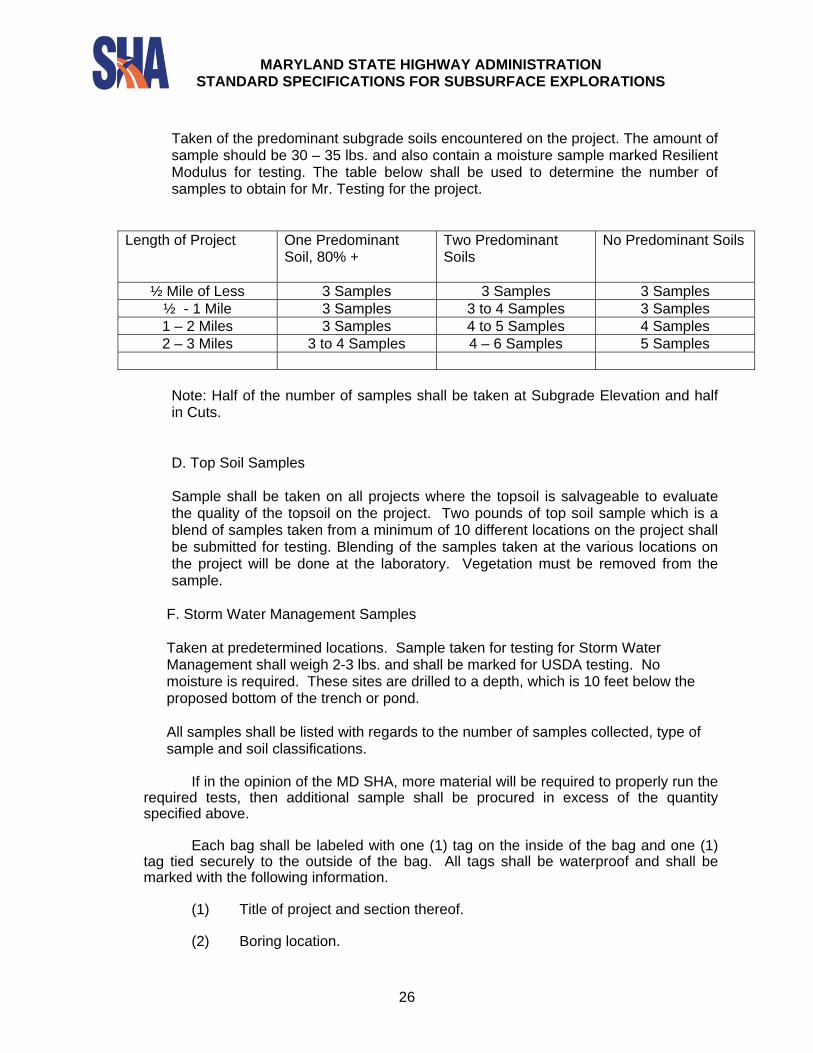
Taken of the predominant subgrade soils encountered on the project. The amount of sample should be 30 – 35 lbs. and also contain a moisture sample marked Resilient Modulus for testing. The table below shall be used to determine the number of samples to obtain for Mr. Testing for the project.
Length of Project One Predominant Soil, 80% +
Two Predominant Soils
No Predominant Soils
½ Mile of Less 3 Samples 3 Samples 3 Samples ½ - 1 Mile 3 Samples 3 to 4 Samples 3 Samples 1 – 2 Miles 3 Samples 4 to 5 Samples 4 Samples 2 – 3 Miles 3 to 4 Samples 4 – 6 Samples 5 Samples
Note: Half of the number of samples shall be taken at Subgrade Elevation and half in Cuts.
D. Top Soil Samples
Sample shall be taken on all projects where the topsoil is salvageable to evaluate the quality of the topsoil on the project. Two pounds of top soil sample which is a blend of samples taken from a minimum of 10 different locations on the project shall be submitted for testing. Blending of the samples taken at the various locations on the project will be done at the laboratory. Vegetation must be removed from the sample.
F. Storm Water Management Samples
Taken at predetermined locations. Sample taken for testing for Storm Water Management shall weigh 2-3 lbs. and shall be marked for USDA testing. No moisture is required. These sites are drilled to a depth, which is 10 feet below the proposed bottom of the trench or pond.
All samples shall be listed with regards to the number of samples collected, type of sample and soil classifications.
If in the opinion of the MD SHA, more material will be required to properly run the required tests, then additional sample shall be procured in excess of the quantity specified above.
Each bag shall be labeled with one (1) tag on the inside of the bag and one (1)
tag tied securely to the outside of the bag. All tags shall be waterproof and shall be marked with the following information.
(1) Title of project and section thereof.
(2) Boring location.
MARYLAND STATE HIGHWAY ADMINISTRATION
STANDARD SPECIFICATIONS FOR SUBSURFACE EXPLORATIONS
27
(3) Sample depth.
TS-14.5 Protection of Samples and Records
The Contractor shall be responsible for the storage and preservation of all samples and records prior to completion of the work, or until such time as they are shipped to the MD SHA. Suitable storage facilities shall be provided so as to protect the samples and records against theft, loss, or damage. All samples to be tested in the laboratory shall be delivered to the MD SHA or other locations to be specified by the MD SHA within 5 days after completing any particular boring. TS-14.6 Visual Description of Samples
The Contractor shall record on the boring log a visual description of all samples, in accordance with the MSMT soils classification system, obtained in the auger borings. This description shall be in accordance with the following:
(1) Kind: Topsoil, clay, silt, sand, gravel, silty clay, sandy silt, etc. (2) Moisture: Dry, moist, wet, saturated, etc.
TS-14.7 Record Data
The Contractor shall record, on 8-1/2 inch by 11 inch standardized boring log forms provided by the MD SHA, the following information for each boring:
(1) Title of project and designation of section thereof.
(2) Date of starting and completing boring.
(3) Hole number.
(4) Names of Contractor, Inspector and Drilling Crew.
(5) Location of site by name, and/or survey station and offset, if any, right or left of centerline.
(6) Ground elevation at hole, as furnished by the MD SHA.
(7) Depth of the top of groundwater after zero hours and 24 hours, if present,
and bottom depth of hole recorded at the same time.
(8) Size and type of auger.
(9) Depth of top and bottom of each soil stratum encountered.
(10) AASHTO or MD SHA approved/designated field classification of material in each stratum.
(11) Depth of bottom of boring.
MARYLAND STATE HIGHWAY ADMINISTRATION
STANDARD SPECIFICATIONS FOR SUBSURFACE EXPLORATIONS
28
(12) Depth of soil samples taken and sample number.
Within twenty-four (24) hours after the completion of each boring, the Contractor
shall hand the MD SHA one (1) legible copy of the driller's log for the boring, prepared to show all relevant data herein specified. TS-15 PATCHING OF BORE HOLES IN BRIDGE DECKS TS-15.1 Patching Procedure The Contractor shall be required to repair all bore holes made on bridge decks prior to moving from the boring locations. The bridge deck bore hole shall be repaired as follows:
1. A “T” bar shall be fabricated from an iron, steel or aluminum bar by cutting a length of bar equal to the diameter of the bore hole plus two (2) inches. A length of treaded rod of the same material as the bar shall be welded to the bar at the center of the bar. The treaded rod shall be sufficiently long to reach through the bridge deck. A metal disk of diameter large enough to just pass through the bore hole shall be fabricated to be attached to the treaded rod by mean of a nut.
2. The bridge shall be notched to receive the excess one (1) inch of bar of the “T” bar handle on either side of the bore hole. The notch shall be ¼ deeper than the diameter of the bar.
3. The “T” bar and the disk shall be inserted into the bore hole and adjusted to match the
depth of the bridge deck.
4. The bore hole shall be filled with a rapid set cementiteous material having a set time of one (1) hour maximum.
5. The surface of the filled bore hole shall be screeded to provide a smooth surface, even
with the adjacent bridge deck.
6. The patched bore hole shall be protected from the weather and traffic until the cementiteous material has set up according to the manufacturer’s recommendations.
TS-16 PAVEMENT CORING
At locations designated by the MD SHA, pavement coring shall be required. The pavement cores shall be made in Bituminous Concrete, Portland Cement Concrete, or Composite Pavements. The Pavement Cores shall be obtained by utilizing a diamond bit attached to the end of the drill rod. The diamond bit will drill a “donut shape” hole in the pavement material and the center is retained and retrieved in the drill rod. The pavement core shall be appropriately labeled and delivered to MD SHA. The diameter of the pavement cores will be specified by the MD SHA in the work assignment request.
MARYLAND STATE HIGHWAY ADMINISTRATION
STANDARD SPECIFICATIONS FOR SUBSURFACE EXPLORATIONS
29
TS-16.1 Measurement and Payment
Measurement of this item will be for each pavement core made in Bituminous Concrete, Portland Cement Concrete, or Composite Pavement regardless of depth of the core. Payment for this item will be made at the unit price per each pavement core in the "Bid or Proposal" which price shall include the coring, recovery, preservation, and delivery of all samples, and all incidental work as specified herein. TS-17 PATCHING PAVEMENT CORE HOLES Upon satisfactory completion of the pavement coring, the Contractor shall be required to patch the hole(s) created by the pavement coring operation. The core hole shall be patched with Bituminous Concrete for Bituminous pavements; Portland Cement for Portland Cement Concrete pavements or Composite patches in Composite Pavements. Patching material shall be placed and compacted in such a way that the entire core hole is completely filled without voids and that the patching material is in close contact with the sides of the core hole. TS-18 FLAT PLATE DILATOMETER
At locations determined by the MD SHA, Flat Dilatometer Tests (DMT) shall be required. The testing may be performed using a special DMT vehicle equipped for this type of testing or from a test drilling machine especially modified to perform this test.
The testing may be performed from by pushing the plate into the ground from the surface or the testing may be started in a previously drilled test hole. The testing apparatus shall be capable of reaching a depth of 100 feet and shall also be capable of penetrating hard clay strata.
The testing shall be performed in accordance with the Standard Test Method for Performing the Flat Plate Dilatometer - ASTM Standard Designation D 6635.
The DMT testing shall be performed such that a computerized or printed table shall be produced that will depict the following: gauge pressure, thrust, A-pressure, B-pressure, dilatometer modulus, dimensionless dilatometer index, dimensionless dilatometer horizontal stress index, pore water pressure, undrained shear strength of cohesive soils, vertical effective stress in one-dimensional compression, overconsolidation ratio, Ko, Phi, constrained modulus of soil compressibility, and soil type. TS-19 PREBORING PRESSUREMETER ( PBPMT)
At locations designated by the MD SHA, Preboring Pressuremeter Tests
(PBPMT) shall be required. The PBPMT tests will consists only of the preboring type where the probe is inserted into a predrilled borehole.
The PBPMT test requires that a test hole be predrilled by the drilling Contractor and that the drilling personnel be available to lower and raise the pressuremeter probe. In boreholes where PBPMT testing is to be performed, hollow stem augers will not be permitted.
MARYLAND STATE HIGHWAY ADMINISTRATION
STANDARD SPECIFICATIONS FOR SUBSURFACE EXPLORATIONS
30
The casing and borehole dimensions shall be coordinated with the PBPMT testing personnel so that the dimensions of the borehole and the shape of the borehole are compatible with the PBPMT testing equipment.
The PBPMT testing shall be performed in accordance with the Standard Test Method for Pressuremeter Testing in Soils, ASTM D 4719. The results of the testing shall include the type of test, boring number, size of probe, description of membrane and sheath on probe, depth of center point of probe, pressure readings at 30 and 60 seconds, volume versus pressure graph, pressuremeter modulus, limit pressure, calibration curves, in-situ stress-strain curve of the soil at each depth. TS-20 VANE SHEAR TESTING
At locations determined by the MD SHA, Field Vane Shear Tests will be required. The testing shall be performed in conjunction with a test boring where soft, saturated cohesive soils are encountered. The dimensions of the field vanes shall be coordinated with the test drilling casing sizes such that the recommended field vane dimensions are compatible with the drill casings. Hollow stem augers will not be permitted in boreholes where field vane shear tests are to be conducted.
The testing shall be performed in accordance with the Standard Method for Field
Vane Shear Test in Cohesive Soils, ASTM D 2573. The test results shall indicate the calculated shear strength of the soil, the test date, boring number, size and shape of the vane, depth of the vane tip, and depth of vane below the bottom of the hole, torque readings, and time to failure of each test. TS-21 LABORATORY TESTING OF RECOVERED SOIL SAMPLES
Laboratory testing consisting of both physical and strength tests of recovered soil
samples will be required. The laboratory testing shall be performed in accordance with the latest edition of Standard Specifications for Transportation Materials and Methods of Sampling and Testing, as published by the American Association of State Highway and Transportation Officials (AASHTO), 444 North Capitol Street, NW, Suite 249, Washington, D.C., 20001, (202) 624-5800 and /or the Annual Book of Standards as published by the American Society for Testing and Materials (ASTM), 100 Barr Harbor Drive, West Conshohocken, Pennsylvania, 19248, (610) 832-9500.
The testing shall be performed in the laboratory of the drilling firm working under
this contract or in a laboratory subcontracted by a drilling firm. The laboratory must be in compliance with and have been inspected in accordance with the Standard Practice for Minimum Requirements for Agencies Engaged in the Testing and/or Inspection of Soil and Rock as Used in Engineering Design and Construction, ASTM D 3740. The testing laboratory shall produce inspection documentation if it has been inspected.
The MD SHA will inspect the testing laboratory for its conformance with the
ASTM 3740 if the lab has not already been inspected. A testing laboratory can be under contract to more than one test-drilling firm.
MARYLAND STATE HIGHWAY ADMINISTRATION
STANDARD SPECIFICATIONS FOR SUBSURFACE EXPLORATIONS
31
The MD SHA will determine the type, number and sequence of soil testing to be performed. The tests will be selected on the basis of priority that will best meet with project schedules and the needs of the design engineers.
Measurement of the laboratory testing will be on a “per each” basis for each test successfully performed. The price paid for each test will include the test results and all laboratory work sheets. Tests that appear to be in error or which have suspect results will be retested at no additional charge to the MD SHA. Should a retest indicate that the initial results were correct, the MD SHA would authorize payment for the retest(s).
Payment for laboratory testing will be on a per each basis for each successful
test as bid in the Proposal for each indicated test. Payment will not be authorized until each individual test result has been received by the MD SHA and the unused samples, properly identified have been delivered to the designated MSHA storage facility.
Subsur_TechSpecs_040401.DOC