Test Methods for the Evaluation of Manufacturing Mobile ...
16
Test Methods for the Evaluation of Mobile Manipulator Safety Paper: Rb28-2-7407: Test Methods for the Evaluation of Manufacturing Mobile Manipulator Safety Jeremy A. Marvel ∗ and Roger Bostelman ∗,∗∗ ∗ National Institute of Standards and Technology 100 Bureau Dr., Stop 8230, Gaithersburg, MD 20899, USA E-mail: {jeremy.marvel, roger.bostelman}@nist.gov ∗∗ IEM, Le2i, Universit´ e de Bourgogne BP 47870, 21078 Dijon, France [Received June 9, 2015; accepted January 18, 2016] This paper presents a test methodology for evaluat- ing the safety of mobile manipulators (robot arms mounted on mobile bases). This methodology ad- dresses the safety concerns relevant to modern, agile, manufacturing practices in which mobile manipula- tors will play a significant role. We consider 1) the unique capabilities and anticipated uses of mobile ma- nipulators and 2) the potential exemptions and special cases in which their behavior may be unpredictable or otherwise contrary to the safety requirements. Fi- nally, we define metrics for assessing compliance with functional safety requirements and anticipated perfor- mance. Keywords: mobile manipulators, AGV safety, robot safety 1. Introduction The need for agility in modern industrial processes is increasing. Traditional paradigms for robotic manipu- lators and controllers are slowly being replaced by sys- tems that are more dexterous, faster, and sensor-driven. As the capabilities and applications of robotics increase, however, the capacity to ensure a safe working environ- ment for humans struggles to keep pace. Even with up- dated safety standards and modern safeguarding technolo- gies in place, robot-related injuries and deaths still occur (e.g., [1]). There is a clear and present need for test meth- ods to verify and validate the safety requirements of cur- rent and next generation robotics. International and national standards efforts are attempt- ing to clearly specify these requirements. However, these efforts are focused on existing robotic technologies such as machine tools (e.g., [2, 3]), industrial robot arms (here- after termed: manipulator) and systems [4–7], and au- tomated guided vehicles (AGVs) [8]. Emerging, novel, and hybrid technologies, such as mobile manipulators, are largely unaddressed. Mobile manipulators are manipula- tors mounted on mobile bases. They combine the agility of manipulators with the mobility of AGVs. They already are being developed and deployed to streamline manufac- turing, healthcare [9], and logistical processes [10]. Such manipulators are quickly becoming an enabling technol- ogy for agile manufacturing. We have previously discussed the application of the ex- isting robot safety standards to mobile manipulators [11]. In that study, we highlighted situations in which these standards are insufficient for providing safe operational conditions. In this paper, we present a series of test methods and metrics to address one of those safety situa- tions: the integration of mobile manipulators into human- occupied industrial settings. These test methods are part of the ongoing efforts at the National Institute of Stan- dards and Technology (NIST) to enable and support the development of safe, collaborative AGV and industrial robot technologies. Section 2 provides a brief overview of mobile manip- ulators and their relationship to the existing safety stan- dards. Section 3 outlines the metrics necessary to verify the safe functionality of mobile manipulators. Section 4 details test methods and potential exceptions of use for identified gaps in the existing standards. 2. Safety Standards Mobile manipulators are a common platform for appli- cations that require a large degree of dexterity deployable in large, unstructured environments. Most such applica- tion domains reside in dangerous environments, where the deployed mobile manipulators are teleoperated by trained experts (e.g., bomb-disposal [12] and search-and- rescue [13] robots). Applying the mobile manipulator paradigm to less hazardous environments (e.g., medical- care [14] and residential service [15]) is an active field of research and development, and focuses on providing the same mobile dexterity to the more mundane setting of hospitals and homes. As of the time this report was written, safety standards do not exist for bomb-disposal, search-and-rescue, or service robots. However, the Inter- national Organization of Standardization (ISO) Technical Committee 184, Subcommittee 2, Working Groups 7 and 8 are developing guidelines for personal care and service Journal of Robotics and Mechatronics Vol.28 No.2, 2016 1
Transcript of Test Methods for the Evaluation of Manufacturing Mobile ...

Test Methods for the Evaluation of Mobile Manipulator Safety
Paper: Rb28-2-7407:
Test Methods for the Evaluation of Manufacturing MobileManipulator Safety
Jeremy A. Marvel∗ and Roger Bostelman∗,∗∗
∗National Institute of Standards and Technology100 Bureau Dr., Stop 8230, Gaithersburg, MD 20899, USA
E-mail: {jeremy.marvel, roger.bostelman}@nist.gov∗∗IEM, Le2i, Universite de Bourgogne
BP 47870, 21078 Dijon, France[Received June 9, 2015; accepted January 18, 2016]
This paper presents a test methodology for evaluat-ing the safety of mobile manipulators (robot armsmounted on mobile bases). This methodology ad-dresses the safety concerns relevant to modern, agile,manufacturing practices in which mobile manipula-tors will play a significant role. We consider 1) theunique capabilities and anticipated uses of mobile ma-nipulators and 2) the potential exemptions and specialcases in which their behavior may be unpredictableor otherwise contrary to the safety requirements. Fi-nally, we define metrics for assessing compliance withfunctional safety requirements and anticipated perfor-mance.
Keywords: mobile manipulators, AGV safety, robotsafety
1. Introduction
The need for agility in modern industrial processes isincreasing. Traditional paradigms for robotic manipu-lators and controllers are slowly being replaced by sys-tems that are more dexterous, faster, and sensor-driven.As the capabilities and applications of robotics increase,however, the capacity to ensure a safe working environ-ment for humans struggles to keep pace. Even with up-dated safety standards and modern safeguarding technolo-gies in place, robot-related injuries and deaths still occur(e.g., [1]). There is a clear and present need for test meth-ods to verify and validate the safety requirements of cur-rent and next generation robotics.
International and national standards efforts are attempt-ing to clearly specify these requirements. However, theseefforts are focused on existing robotic technologies suchas machine tools (e.g., [2, 3]), industrial robot arms (here-after termed: manipulator) and systems [4–7], and au-tomated guided vehicles (AGVs) [8]. Emerging, novel,and hybrid technologies, such as mobile manipulators, arelargely unaddressed. Mobile manipulators are manipula-tors mounted on mobile bases. They combine the agilityof manipulators with the mobility of AGVs. They already
are being developed and deployed to streamline manufac-turing, healthcare [9], and logistical processes [10]. Suchmanipulators are quickly becoming an enabling technol-ogy for agile manufacturing.
We have previously discussed the application of the ex-isting robot safety standards to mobile manipulators [11].In that study, we highlighted situations in which thesestandards are insufficient for providing safe operationalconditions. In this paper, we present a series of testmethods and metrics to address one of those safety situa-tions: the integration of mobile manipulators into human-occupied industrial settings. These test methods are partof the ongoing efforts at the National Institute of Stan-dards and Technology (NIST) to enable and support thedevelopment of safe, collaborative AGV and industrialrobot technologies.
Section 2 provides a brief overview of mobile manip-ulators and their relationship to the existing safety stan-dards. Section 3 outlines the metrics necessary to verifythe safe functionality of mobile manipulators. Section 4details test methods and potential exceptions of use foridentified gaps in the existing standards.
2. Safety Standards
Mobile manipulators are a common platform for appli-cations that require a large degree of dexterity deployablein large, unstructured environments. Most such applica-tion domains reside in dangerous environments, wherethe deployed mobile manipulators are teleoperated bytrained experts (e.g., bomb-disposal [12] and search-and-rescue [13] robots). Applying the mobile manipulatorparadigm to less hazardous environments (e.g., medical-care [14] and residential service [15]) is an active fieldof research and development, and focuses on providingthe same mobile dexterity to the more mundane settingof hospitals and homes. As of the time this report waswritten, safety standards do not exist for bomb-disposal,search-and-rescue, or service robots. However, the Inter-national Organization of Standardization (ISO) TechnicalCommittee 184, Subcommittee 2, Working Groups 7 and8 are developing guidelines for personal care and service
Journal of Robotics and Mechatronics Vol.28 No.2, 2016 1

Marvel, J. A. and Bostelman, R.
robotics, respectively.Vendors of industrial mobile manipulators do not pro-
vide an off-the-shelf, fully integrated, fully autonomous,arm-on-mobile-base capability. Instead, mobile manip-ulator solutions take the form of teleoperated and semi-autonomous platforms for targeted applications. Thesesolutions, however, are expensive, tend toward the proven(but limited) sensing and control functions of classicalAGV design, and are restricted to constrained tasks. Themobile base and the manipulator are frequently treated asseparate components, with the base being used to cart andpark the manipulator to task-relevant locations. Control-ling the mobile manipulator in this manner is conceptu-ally easier, and, generally speaking, safer because it isnot clear when and which safety standards should be en-forced.
2.1. AGV StandardsIn the U.S., the joint American National Standards In-
stitute (ANSI)/Industrial Truck Standards DevelopmentFoundation (ITSDF) standard B56.5-12 [8] defines thesafety requirements for the design, operation, and main-tenance of AGVs. In Europe, AGVs must complywith the safety requirements in Machinery Directive2006/42/EC [16]. European vendors of AGVs must usea type C-standard, EN1525 [17] to show conformance tothose requirements. Attempting to harmonize the numer-ous national safety standards internationally, the ISO draftinternational standard (DIS) 3691-4.2 was in developmentfor many years. ISO/DIS 3691-4.2 was never finished,however, and was deleted because the state-of-the-art ofAGV technology surpassed the information discussed inthe draft standard.
The next generation of AGV safety standards are ex-pected to include several new criteria for 1) measuringdynamic obstacles and obstacles appearing in the “excep-tion” or stop zone, 2) three dimensional (3D) imagingfrom an AGV to detect overhanging obstacles, 3) mannedvehicles with automated functions when operators cannotsee pedestrians, 4) detection of humans (in line-of-sight oroccluded) and located near AGVs using non-contact sen-sors [18], and 5) manipulators onboard AGVs, also withhuman detection from non-contact sensors.
2.2. Industrial Robot StandardsThe international guidelines for the safety of industrial
robots are provided in the two parts of ISO 10218 [4, 5].Part 1 outlines the requirements for the construction andcontrol of robots. It includes provisions for elements suchas electrical connectors, control modes, axis limiting, andactuation. Part 2 establishes the safety requirements forintegrated robot systems. It includes safeguards, externalaxes, and the integration of multiple robots and machinetools. Together, both parts of ISO 10218 ensure safetythroughout the robot workcell. ANSI and the RoboticsIndustries Association (RIA) adopted both parts of ISO10218 in 2012 for the joint ANSI/RIA R15.06 [7] U.S.national standard on robot safety.
Robot safety is concerned with the safety of the humansworking near robots. The classical method of ensuringoperator safety has been to enforce a strict separation ofman and machine by way of physical barriers (e.g., [19]).The 2011 revision of ISO 10218 added language sup-porting limited human-robot collaboration per the guide-lines of the ISO Proposed Draft Technical Specification(PDTS) 15066 [6]. ISO/PDTS 15066 provides two mech-anisms for ensuring operators safety: 1) speed and sepa-ration monitoring (SSM), and 2) power and force limiting(PFL). SSM enforces a minimal separation distance be-tween a human and a moving robot. The robot’s speedis scaled down or stopped based on the measured speedof the human. This ensures that the robot will stop in asafe and controlled manner without making contact withthe human. PFL, in contrast, assumes that the robot andhuman will make contact, and enforces the rule that anyapplied forces and pressures will not cause harm. Thesepower and force limits were previously based on a litera-ture review of injury criteria [20]. However, these valueswill eventually be replaced by the results of an ongoingpain threshold study at the Johannes Gutenberg Univer-sity in Mainz, Germany [21].
2.3. Standards and Mobile ManipulatorsAs a necessary prerequisite, we evaluated the AGV
and industrial robot safety standards to discern the ar-eas where there is sufficient coverage and the areas wherethere is little to no provision for risk minimization.
That evaluation was based on a representative, but notexhaustive, list of risk scenarios involving mobile manip-ulators.1 This list is shown in Table 1, which also listsrelevant standard(s) that provide language for maintaininga safe operating environment for humans. For each sce-nario, we considered the various combinations of move-ment and control of the robot and AGV. We made a dis-tinction between single versus dual control because het-erogeneous robot control and coordination is neither welldefined nor formally supported by the existing standards.
Table 1 shows considerable overlap between the indus-trial robot and AGV safety standards as they apply to mo-bile manipulators. Both standards, for instance, containlanguage to minimize the risks associated with the un-expected enabling of AGV and robot drive motors (sce-nario a) and for handling the presence of people/objectswithin the robot’s work volume and AGV’s path (sce-nario c, first sub-condition). Where a single controllerdrives the mobile manipulator system, the language inboth the industrial robot and AGV standards provides ad-equate provisions for human safety (see scenarios k andl).
In many cases, the risks associated with the operationalconditions are specific to either the manipulator or theAGV base. In such cases, additions to the respective stan-dards may provide suitable coverage for the entire mo-bile manipulator. For example, language for handling the
1. The user can create their own list of safety-related scenarios from a riskassessment of the hazards of the user’s environmental and operationalconditions.
2 Journal of Robotics and Mechatronics Vol.28 No.2, 2016

Test Methods for the Evaluation of Mobile Manipulator Safety
Table 1. Example operational conditions from [11] that have limited or no coverage in either the AGV (A) or robot (R) safetystandards using either a single- or dual-controller mobile manipulator configuration. Conditions marked with “A/R” are covered byboth the AGV and robot standards, while cells marked with “--” are not covered by either.
y Moving AGV +
Stationary Robot Stationary AGV + Moving Robot
Moving AGV + Moving Robot
Single Dual Single Dual Single Dual a Unexpected startup of robot or AGV A/R A/R A/R A/R A/R A/R b Robot/AGV hardware safety interlock A/R A/R A/R A/R A/R A/R
c
Human approach angle other than current direction of AGV travel, human is… …in robot work volume, in AGV path …out of robot work volume, in AGV path …in robot work volume, out of AGV path
A/R A R
A/R A R
A/R A R
A/R A R
A/R A R
A/R A R
d AGV position uncertainty A1 A1 A1 A1 A1 A1 e Robot position uncertainty R2 R2 R2 R2 R2 R2 f Conflicting emergency stop situations A A A A A A g Robot sensing within the restricted space A A A/R3 A/R3 A A h Mobile manipulator stability A4 A4 A4 A4 A4 A4 i Overhanging obstacle extends into robot or AGV path A5 A5 A5 A5 A5 A5 j Reporting joint configuration of robot A/R A A/R A A/R A k Robot/AGV inhibiting motion of the other A/R6 A A/R6 A A/R6 A l Planned/automatic restart from pause/stop A/R A A/R A A/R A m Sensing beyond vehicle path A/R R A/R R A/R R n Competing/incompatible safety protocols A/R -- A/R -- A/R -- o Human carrying large load into AGV/robot path and vice versa -- -- -- -- -- -- p Velocity of any point greater than that of AGV/robot Not Applicable R -- q Unplanned restart from pause/stop A/R -- A/R -- A/R -- r Error recovery startup R -- R -- R -- s AGV/robot software safety interlock R -- R -- R -- t AGV/robot position/configuration update and verification A/R -- A/R -- A/R -- u AGV/robot assumes master control during a pause event A7 -- A7 -- A7 --
1 ANSI/ITSDF B56.5 requires detection of obstacles only within the planned AGV path 2 per ISO 9283 [22]
3 ISO10218-2 requires sensing within a restricted, safeguarded spaces, possible only if the AGV is not moving 4 Partial. Per ANSI/ITSDF B56.5, 4.2.5, 9.2.2: “Only stable or safely arranged loads shall be handled”
5 ANSI/ITSDF B56.5 requires only standard test pieces to be detected within the contour area 6 ANSI/ITSDF B56.5 and ISO 10218-2 each cover part of the motion inhibition requirements, neither covers both separately
7 ANSI/ITSDF B56.5 is not specific to onboard equipment causing a fault
robot position uncertainty (scenario e), and the gravita-tional stability of the mobile manipulator (scenario h), isprovided in the robot and AGV safety standards, respec-tively. This generally holds true for the dual-controllercondition; but, in cases where there is inconsistent or oth-erwise conflicting handing of operational conditions, thelanguage of the robot and AGV standards is insufficientfor maintaining safety.
In Section 4, we focus exclusively on providing testmethods for scenarios n through u from Table 1. Thesewere selected because they each contain configuration op-tions for which there is no coverage within existing safetystandards.
3. Metrics for Mobile Manipulator Safety
Numerous metrics have been defined for evaluating thesafety of robot systems. Traditionally, most metrics takethe form of binary evaluations: does the machinery stopwhen specific events occur, or not? Typically, this resultsin the strict separation of man and machine. As efficiencyand agility requirements increase in manufacturing, strictseparation will not be possible. Activities such as auto-mated assembly will require some level of co-location ofhumans and robots. These requirements provide quan-tifiable guidance for metrics such as minimum separationdistances [7] and maximum safe operational speeds [8].
3.1. Separation Metrics
Anticipating the need for physical interactions betweenhumans and robots, the next generation of safety stan-dards will have established limits on the transfer of forcesand pressures from the robotic system to a human opera-tor (e.g., [7]). However, these limits are still experimen-tal; and, their functional safety – though considered to beoverly conservative – has not been validated [23]. Untilvalidated, these limits will not be included in mobile ma-nipulator testing methodologies. Instead, the test meth-ods described in this paper assess the effectiveness of thesafety standards, sensors, and functions for maintaining asafe separation distance.
A safe separation distance is defined to be a minimumacceptable separation between an active mobile manip-ulator’s constituent components and any humans aroundit. While the mobile manipulator is moving, this mini-mum separation distance, which should be maintained atall times, is 850 mm (assuming normal direction of ap-proach [3]) or the AGV’s minimum stopping distance,whichever is greater. This minimum separation distancemay be reduced to 0.0 m while the mobile manipulator isin a safe paused or stopped state.
The separation distance is measured in 3D using a sim-ple Euclidean distance based on the closest point of ap-proach (see Fig. 1). During the evaluation of the testmethods in Section 4, these distances may be verified forexample, via calibrated tracking systems and downward-facing camera systems. Note, however, that the true sepa-ration distance may be greater or smaller than the observ-
Journal of Robotics and Mechatronics Vol.28 No.2, 2016 3

Marvel, J. A. and Bostelman, R.
Fig. 1. The separation between the human and the mobilemanipulator is measured at the closest point of approach,which may be on the AGV or on the robot arm.
ing system reports due to perspective or scaling. This isillustrated in Fig. 1 where the side view of the encountersituation suggests that the closest point on the mobile ma-nipulator is the gripper on the manipulator, while the topview puts the closest point on the AGV’s wheel. In reality,the closest point is on the side of the AGV.
Note, these metrics do not consider direction of travel.In some cases, the closest point of approach may beachieved even though the separation distance between themobile manipulator and human is increasing. This canhappen, for example, when the arm is rotating to a storedposition as the human is walking away from the AGVbase. Hence, our test methods do not consider the kine-matics or capabilities of the mobile manipulators. Rather,these methods assume that the mobile manipulator canchange direction instantaneously.
The test methods described in Section 4 are intendedfor the verification of mobile manipulator safe functional-ity, and are not intended to prescribe safety systems. Be-cause these test methods require 3D tracking of the mobilemanipulator and obstacles in the environment, the sepa-ration distances may be evaluated post facto. However,because the maintenance of these separation distances isnot verified in real time, no human should be inside thetesting area while these evaluations are occurring.
3.2. Functional Stopping MetricsThe mobile manipulator should come to a controlled
stop when being paused. Controlled stops require that1) the constituent components of a mobile manipulatormaintain adherence to their trajectories, and 2) the AGVdoes not lose traction or cause held/carried objects to fallor be dropped. These actions should be predictable andrepeatable.
The manipulator may be required to make an emer-gency stop. Such stops should take effect immediately,without guarantee for path maintenance. Sudden momen-tum changes may cause held/carried objects to fall. Heldand carried objects should be controlled or secured such
that dropped objects do not constitute a hazard.While paused or stopped, the constituent components
of the mobile manipulator shall remain stationary and allstored energy remains in a safe, controlled state. Theseconditions remain in effect until a restart command is is-sued either manually or automatically per safety proto-cols.
3.3. Human Detection and ArtifactsIn our previous paper [11], we discussed the need for
improved biosimulant test pieces and human-specific de-tection test methods. Such artifacts and test methods arecritical to the verification and validation of safe opera-tions of industrial robots as the physical barriers that sep-arate them from humans disappear. It is likely that the testmethodology presented in this paper will adapt to incor-porate them as these technologies and test methods evolveand mature.
4. Evaluative Test Methods
In this section, we provide test methods and perfor-mance evaluation requirements for scenarios n–u fromTable 1 and label each with a test number from onethrough eight. For each scenario, we present configura-tion setup descriptions, procedural guidelines, and rele-vant measurements. When applicable, “special case” ex-ceptions are also given. These exceptions demonstratethat the risk assessment process may include conditionsthat either contradict or bypass the expected safe behav-ior of a mobile manipulator. Such special cases are pro-vided for illustration purposes only, and are not exhaus-tive. Integrators and users should perform an evaluativerisk assessment of specific applications to verify safe useof mobile manipulators during such operations.
During each test, proper safety precautions should betaken. Humans are not allowed inside the test area whilethe tests are running, and appropriate personal protec-tive equipment (e.g., safety glasses and appropriate pro-tective footwear) should be worn at all times during thetests. Standardized test pieces (Fig. 2, [4, 8]) should beused when applicable, or other biosimulant artifacts (e.g.,mannequins) used when possible. Appropriate emergencystop devices should be in place, and all personnel trainedin their use.
All suggested test methods in this section are expectedto be feasible for manufacturers, users, and systems inte-grators to employ. Standard test methods are developedto ensure repeatability of the test by anyone who uses ordevelops the systems, i.e., mobile manipulators. The testmethods discussed in this section are designed to be con-ceptually simple to understand and simple to implement.
4.1. Test 1: Competing/Incompatible Safety Proto-cols (n)
When producing a mobile manipulator solution thatfollows established standards, an integrator must consult
4 Journal of Robotics and Mechatronics Vol.28 No.2, 2016

Test Methods for the Evaluation of Mobile Manipulator Safety
1 2 3
A B
Fig. 2. Current test pieces used by the AGV (A) and industrial robot (B) standards. (A) shows the 1) vertical (shown being used formeasuring bumper force) 70 mm dia. × 400 mm tall, 2) horizontal 200 mm dia. × 600 mm long, and 3) flat plate 0.5 m square testpieces with their proper coatings. (B) shows the range of artifact radii as a function of the detection zone height.
available national requirements for the constituent parts.However, in the U.S., the AGV and industrial robot safetystandards are not completely compatible. When integrat-ing a dual-controller solution, the two standards may becontradictory with regards to certain requirements. Whenone control protocol mandates a pause or stop, but theother control protocol requires a completely different re-sponse, the results may cause unpredictable and unsafebehaviors. Example behaviors could include:
1. The AGV continues to move when the manipula-tor is emergency stopped in an extended configura-tion. Without the AGV detecting the extended arm,the AGV may continue motion causing an additionalhazard.
2. The manipulator may continue to move when theAGV is emergency stopped. The manipulator maythen extend beyond the AGV and collide with obsta-cles or humans that caused the AGV to stop.
Single-controller systems may circumvent some ofthese behaviors, but the integrator must identify the con-flicts and choose which functions to implement. The cur-rent standards do not provide such guidance.
Ideally the existing standards would be harmonized toremove or resolve conflicts and provide appropriate guid-ance. Until this happens, test methods should identifyconflict states. Here, we provide one such test method toverify three separate conditions. First, in a dual-controllerconfiguration, which controller (the AGV’s, the manipu-lator’s, or both the AGV and manipulator) has emergencycontrol to stop, pause, or command motion of the mov-able components of a mobile manipulator? Second, ina single-controller configuration, are the commanded re-sponses compatible with the chosen standard’s safety re-quirements? Third, in either a single- or dual-controllerconfiguration, are the responses to potential hazards safe?
4.1.1. Test MethodologyTo evaluate the functional response to competing or in-
compatible safety standards protocols, the proposed test
Fig. 3. Test configuration to determine command authorityand identify potential conflicts between the AGV and indus-trial robot arm safety standards.
method involves the mobile manipulator configured as il-lustrated in Fig. 3. The basic test method consists of thefollowing steps.
1. Align the AGV to move forward along a straightpath, with the arm extended statically to the right orleft beyond the AGV’s width.
2. Position an obstacle (block, mannequin, or standard-ized test piece) to the side of the AGV, outside of theAGV’s path, but within the path of the extended arm.
3. Move the AGV forward along the straight path at itsnormal application operational speed.
4. The AGV should stop prior to the arm making con-tact with the obstacle. (Optional supporting safetymaneuver: static arm retracts prior to contact withthe obstacle.)
5. Repeat Steps 1–4 for the arm moving back-and-forthnormal to the travel direction of the AGV. Both theAGV and the manipulator should stop prior to thearm making contact with the obstacle.
Depending on the safety standard being referenced andthe controller configuration, the responses to the above
Journal of Robotics and Mechatronics Vol.28 No.2, 2016 5

Marvel, J. A. and Bostelman, R.
testing scenario are expected to be different. For exam-ple, the U.S. AGV standard allows, although not explic-itly, static and moving components to be automaticallymoved after a safety stop and after the hazard has beenremoved. In the mobile manipulator case, this situationmight, for example, include changing the forward motionprofile of the AGV by moving the robot to its stowed con-figuration to remove the collision hazard. In contrast, theU.S. industrial arm safety standards require the robot tostop completely – either an emergency or a safety rated,monitored stop [7] – prior to collision. However, there isno guidance as to how the stop is propagated or validated.For instance, the moving manipulator may come to a com-plete stop while the AGV is still moving. Or, the movingAGV may come to a complete stop while the manipulatoris still moving.
4.1.2. Special Risk Assessment Case ExampleThe above test methodology may illustrate behaviors
that are incompatible with the intended application of amobile manipulator. Although the reaction to a perceivedhazard may be considered safe, the actual result could po-tentially be undesirable. For instance, say that the obstacleis a part or fixture to be accessed by the manipulator whilethe mobile manipulator is in motion. Upon approach, thepart could be classified within the generic test method asbeing an obstacle. The safe response would halt the mo-bile manipulator or store the arm, even though the appli-cation intends for the arm to access the part.
4.2. Test 2: Human Carrying Large Load intoAGV/Manipulator Path (o)
Any given robot safety system’s protective sensing ca-pabilities are limited by the underlying sensing technolo-gies employed. Industrial robot safety standards requirethat safety sensors monitor workcell entrances and oper-ational zones within the workcell. However, the very na-ture of the mobile manipulator renders the workcell con-cept moot. Moreover, AGV safety standards require 3Dmonitoring of regions surrounding the vehicle, but pro-vide minimal specific sensor resolution (i.e., must sensethe standard test piece) and no accuracy requirements, orany guidance as to how to implement such sensing sys-tems. There are, however, no 3D safety-rated technolo-gies currently acceptable as the sole means of provid-ing protection of a safeguarded space [9]. Consequently,since most such systems are 2D in nature, they are sus-ceptible to limitations of approach angles and occlusions.As a result, although an AGV and an industrial robot areboth expected to detect intrusions into their respectiveprotected zones [2–8], several conditions exist in whichsafety may be compromised.
When large workpieces carried by human operators en-ter the protected regions of either manipulators or AGVs,these pieces may not be detected in time or at all. Dur-ing collisions, impact forces may be transferred throughthe workpiece to the operator. Mobile manipulators posean additional risk with their unrestricted work volumes,
Fig. 4. Test configuration to determine mobile manipulatorresponse to large loads being carried into the AGV or robotarm path.
complicating attempts to monitor and prevent hazard con-ditions. Example behaviors could include:
1. The long material being carried could be smallerthan or not conform in geometry to standard testpieces such that AGV or robot safety sensors do notdetect the material.
2. The manipulator, being required to sense one geo-metric test piece, may not sense the AGV test piecesand vice versa for the AGV not being able to sensethe manipulator test piece (see Fig. 2).
Because of these concerns, our method evaluates 1) thecapabilities of a mobile manipulator to correctly identifylarge payload conditions regardless of the angle of ap-proach, and 2) the capacity of the safety system to stopor pause the motions of the manipulator and AGV.
4.2.1. Test MethodologyOur evaluation methodology and test method involve
the mobile manipulator configured as illustrated in Fig. 4,and follows the steps below.
1. Align the AGV to move forward along a straightpath, and statically position the manipulator suchthat it extends above and beyond the AGV’s height.
2. Position obstacle of different size/shape from AGVand manipulator standard test pieces [4, 8] – abovethe AGV and below the manipulator extended height.
3. Move the AGV forward along the straight path at itsnormal application operational speed.
4. The AGV should stop prior to the arm making con-tact with the obstacle. (Optional supporting safetymaneuver: static arm retracts prior to contact withthe obstacle.)
5. Repeat Steps 1–4 for an arm, moving cyclicallyback-and-forth, reaching above the moving AGV.Both the AGV and the manipulator should stop priorto the arm making contact with the obstacle.
6 Journal of Robotics and Mechatronics Vol.28 No.2, 2016

Test Methods for the Evaluation of Mobile Manipulator Safety
4.2.2. Special Risk Assessment Case ExamplePresence-sensing safety systems such as laser scanners
and laser gates are indiscriminate evaluators of the areaaround a robotic system. As a result, a large compo-nent being held by the AGV or the manipulator may inad-vertently and incorrectly trigger an emergency stop/pauseevent. Similarly, in a dual-controller configuration, theproblem is that the manipulator and/or the AGV may ac-cidentally elicit emergency stop/pause events in one an-other. One remedy to this problem is to have the con-troller ignore all sensor information related to the motionsof held workpieces or onboard equipment. However, un-til such controller capabilities are validated and availableto the public, integrators should take special care whenplacing and orienting sensors. Similarly, users should becognizant of the mobile manipulator’s potential to “self-trigger” (i.e., the separate components sensing one an-other, detect the other as a potential obstacle) when pro-gramming coordinated motions.
4.3. Test 3: Velocity of Any Point Greater ThanThat of AGV/Robot (p)
The safe stopping functions of both industrial manip-ulators and AGVs rely on accurate estimates of the cur-rent velocity. As the complexity and dexterity of roboticsystems increase, however, the actual velocity of a roboticsystem is difficult to define, let alone compute. An AGV’svelocity, for example, is determined by the instantaneousspeed and direction in which the AGV is traveling. Formanipulators, the situation is quite different. In the latestdraft (as of September, 2013) of ISO TS 15066, the cal-culation for SSM (see Section 2.2) uses only the manip-ulator’s speed but does not take into consideration traveldirection. The term “robot speed” is not well defined. Themost common interpretation calculates manipulator speedas the Cartesian motion of the tool flange. This interpreta-tion is limited, particularly because different parts of themanipulator may actually move faster than the tool flangefor certain motions.
In agile manufacturing applications, AGVs and manip-ulators will be integrated to form a mobile manipulator.It is likely that in particular applications, they will movesimultaneously. Because of this, we expect that the ac-tual velocity of any point on a mobile manipulator willbe greater than any of the component speeds taken sepa-rately. Example behaviors could include:
1. The manipulator rotates its base 90◦ or greater fromthe aft AGV end to the side while the AGV is mov-ing forward. The manipulator end-of-arm tool ve-locity added to the AGV velocity would therefore begreater than only the AGV speed where the AGV ormanipulator may not be able to detect obstacles andstop in time to prevent a collision with the obstacle.
2. While the manipulator is moving, the AGV suddenlymoves in the same tangential direction to the end-of-arm tool where AGV reaction may not be able to stopthe mobile manipulator in time to prevent a collision.
Fig. 5. Test configuration to determine mobile manipulatorhandling of the potential for the velocity of any point on therobotic system being faster than the individual speeds of theconstituent parts.
It is therefore vital that these speeds be monitored inreal time to maximize safety performance. Ideally, theCartesian velocities of all actuated joints and attachedcomponents on a mobile manipulator would be knownand shared at all times. None of this information is pro-vided by stock controller configurations. As a minimum,however, the Cartesian velocities of rigid parts nearest todetected obstacles should be approximated as they movetoward potential collision states.
The test method described below evaluates whether amobile manipulator can successfully track and compen-sate for the combined speed of the manipulator and AGV.Specifically, the test method will evaluate whether the mo-bile manipulator responds appropriately, and can success-fully remove the hazard before a collision occurs.
4.3.1. Test MethodologyFigure 5 illustrates the configuration of the mobile ma-
nipulator for this evaluation. The basic test method, be-low, consists of Steps 1–8. Steps 1–5 assess the safe stop-ping behavior of the mobile manipulator, while Steps 6–8establish the functional adherence to established roboticsystem speed limits.
1. Align the AGV to move forward along a straightpath, with the arm set in position 1 as illustrated inFig. 5.
2. Position an obstacle (block, mannequin, or standard-ized test piece) to the side of the AGV, outside of theAGV’s path, but directly within the path of the armwhen it is in or moving towards position 2.
3. Move the AGV forward along the straight path at itshighest application operational speed.
4. During the AGV movement, rotate the manipulator’sbase joint to cause manipulator to move between po-sition 1 and position 2. The end-of-arm-tool flangewill move faster through world coordinate space thanthe AGV.
5. Verify that the AGV and manipulator slow or stopbefore the arm can collide with the obstacle.
Journal of Robotics and Mechatronics Vol.28 No.2, 2016 7

Marvel, J. A. and Bostelman, R.
6. Place a tracking marker on the end-of-arm-toolflange on the manipulator.
7. During the combined AGV-arm motion, track themarker in world Cartesian space.
8. Calculate the velocity and acceleration profiles ofthe tracked marker, smoothing the data with a low-pass filter, if necessary. Verify that the AGV and/ormanipulator slow so the combined end-of-arm-toolspeed never exceeds the highest application opera-tional speed allowed.
4.3.2. Special Risk Assessment Case ExampleOn some movements – for example, when the manip-
ulator is moving from position 2 back to position 1 – theAGV is effectively moving in one direction while the ma-nipulator is moving in another direction. Such a situa-tion can occur when the manipulator moves to remove apotential hazard with an actual velocity (as measured bythe tool flange velocity, with respect to the world) that islower than the velocity limit. However, a second hazardappears in the new manipulator movement path, i.e., op-posite to the arm direction of travel.
There is a related concern if the mobile manipulator iscarrying or holding a large object. While the AGV is turn-ing or the arm is moving, the motions may result in a largemoment arm with the large object that far exceeds the ve-locity limitation. Because neither the industrial robot norAGV safety standards require all points on the held ob-jects to be tracked, it is possible that velocity limits maybe violated through the normal course of operation.
In both cases, internal representations of AGV and ma-nipulator trajectories do not adequately capture the po-tential for collision. As such, a self-centric perspective ofcollisions may not provide sufficient protection dependingon the vectors of AGV and manipulator motion. Rather,mechanisms for modeling relative to a world coordinateframe are likely to be required.
4.4. Test 4: Unplanned Restart from Pause/Stop (q)The AGV and industrial robot safety standards con-
tain language for handling the unexpected restart from astopped or paused state. In both cases, the robotic systemis expected to perform an emergency stop immediately. Inthe single-controller configuration, this is handled inher-ently. However, there are no such requirements when in-tegrating a dual-controller mobile manipulator configura-tion. When recovering from a pause or stop state, restart-ing the motion of a mobile manipulator may trigger anemergency response from either the manipulator or themobile base. If one component starts moving while theother is stopped, the stationary component may interpretthis motion as a failure to maintain the inactive state. Therequired response is to initiate an emergency stop. Dif-ferent circumstances may require an emergency responsewhenever the manipulator or AGV base moves unexpect-edly. Example behaviors could include:
1. After an unexpected manipulator restart and with-out, for example, the AGV receiving manipulatorrestart notification, the AGV could begin drivingwhile the manipulator is extended and even movingwhich could cause a collision with objects local tothe mobile manipulator.
2. The opposite example to 1. is that the manipula-tor could begin moving after an unexpected AGVrestart. Without the manipulator receiving AGVrestart notification, the vehicle could be movingagain, while the manipulator is moving and cause acollision with objects local to the mobile manipula-tor.
The test method described below is used to determinewhether a mobile manipulator will respond appropriatelyto an unplanned restart condition. By testing situationsthat may result in either the AGV or manipulator attempt-ing to move while the other remains in a stopped or pausedstate, we can determine whether the mobile manipulator,1) responds appropriately to potentially conflicting safetystates; and 2) responds correctly when either the arm orthe AGV begin moving when the other is not expecting itto do so.
4.4.1. Test MethodologyOn some movements – for example, when the manip-
ulator is moving from position 2 back to position 1 – theAGV is effectively moving in one direction while the ma-nipulator is moving in another direction. Such a situa-tion can occur when the manipulator moves to remove apotential hazard with an actual velocity (as measured bythe tool flange velocity, with respect to the world) that islower than the velocity limit. However, a second hazardappears in the new manipulator movement path, i.e., op-posite to the arm direction of travel.
There is a related concern if the mobile manipulator iscarrying or holding a large object. While the AGV is turn-ing or the arm is moving, the motions may result in a largemoment arm with the large object that far exceeds the ve-locity limitation. Because neither the industrial robot norAGV safety standards address the issue of monitoring ve-locities of connected components, it is possible said con-nected components may retain or regain activity withoutthe monitoring systems knowledge.
To evaluate the functional response to an unplannedrestart from a pause/stop event, we developed a testmethod based on the configuration shown in Fig. 6. Thecurrent AGV safety standards allow for an automaticrestart 2 s after a potential collision has been cleared.Many commercial AGVs have this functionality enabled,but it is not required. This test methodology utilizes thisand follows the steps below.
1. Align the AGV to move forward along a straightpath, with the arm extended to the right or left be-yond the AGV’s width.
2. Position an obstacle in the path of the AGV, but notin a location where it could collide with the manipu-lator.
8 Journal of Robotics and Mechatronics Vol.28 No.2, 2016

Test Methods for the Evaluation of Mobile Manipulator Safety
Fig. 6. Test configuration to determine mobile manipulatorresponse to unplanned motions following a pause or stop.
3. Move the AGV forward along the straight path atits normal application operational speed. Simultane-ously, move the manipulator back-and-forth normalto the travel direction of the AGV.
4. As the AGV approaches the obstacle, both it and themanipulator should pause or stop their motions.
5. Once both the AGV and the arm have stopped, placea second obstacle next to the AGV, just forward ofthe manipulator, ensuring that any motion of the armor the AGV will cause the arm to collide with theobstacle.
6. Remove the first obstacle that is blocking the AGV’spath. This will clear the first possible collisions state,but the second collision state still exists. (Take pre-cautions when removing the obstacle from the testsite, as the AGV may begin to move again after 2 s.)
7. Determine whether the AGV moves or does notmove with the arm’s collision hazard still in place.If either the arm or the AGV begin to move, deter-mine whether the mobile manipulator immediatelyenters a pause or stopped state.
8. Repeat Steps 1–7, reversing the order of the intro-duction of obstacles to the mobile manipulator.
4.4.2. Special Risk Assessment Case ExampleIn some scenarios, the AGV or manipulator may con-
tinue moving while the other is in a paused or stoppedstate. Suppose the mobile manipulator is paused becauseof a potential collision state between the manipulator andsome obstacle. This conflict may be resolved by com-manding the AGV to move around the obstacle while themanipulator is stationary. In a dual-controller configura-tion, unless this command information is explicitly sharedbetween the arm and the AGV, the AGV’s motions mayresult in an emergency shutdown.
4.5. Test 5: Error Recovery Startup (r)A robotic system enters an error state whenever some
functional constraint has been violated. Such constraints
Fig. 7. Test configuration to determine mobile manipulatorerror recovery precedence.
may include program integrity, motor torque constraints(e.g., collision detection), joint velocity limits, and vir-tual axis limits. Some of these violations cause errors thatwill force the robotic system to stop working. The indus-trial robot safety requirements mandate that an establishederror recovery procedure be in place when this happens.This procedure enables the manipulator to safely restartfrom such errors. The AGV safety standards have no suchrequirement.
In a single-controller configuration, information aboutthe status of either component is always available to theother component. So, one component will be automati-cally aware when the other component is returning froman error state. However, in a dual-controller configura-tion, this information is not automatically available; itmust be communicated and shared explicitly. No sharingrequirements or communication protocols exist for thisfunctionality. Example behaviors could include:
1. A dual-controller mobile manipulator is in an errorstate. When coming back online, the manipulatorsees that the AGV is in an error state, and immedi-ately goes back into an error state, itself.
2. Similarly, when the AGV comes back online, it seesthat the manipulator is in an error state, and then im-mediately reverts back to an error state. The effectis that error recovery is caught in a perpetual error-inducing loop.
If this happens, exception handling or manual interven-tion is required to restart the system components safelyand in the correct order, if known. As a minimum, a mo-bile manipulator standard must specify error recovery re-quirements and procedures to determine precedence.
The purpose of this test is to 1) determine how an errorstate would be propagated from a manipulator to an AGV,and vice versa, and 2) how an operator would effectivelyrecover from an error state involving an AGV and a ma-nipulator in perpetual error propagation events.
4.5.1. Test MethodologyTo evaluate the startup precedence when recovering
from an error, the proposed test method involves the mo-bile manipulator configured as illustrated in Fig. 7, andfollows the steps below:
Journal of Robotics and Mechatronics Vol.28 No.2, 2016 9

Marvel, J. A. and Bostelman, R.
1. Place the AGV on blocks such that it will not moveif the wheels turn. (This is a safety precaution andnot part of the test method itself.)
2. Initiate a joint/torque/current error in the manipula-tor. (For example, such an error can be induced bythe following. Position the inactive manipulator overan immovable object. Insert a pneumatic cylinderor inflatable jack between the end-of-arm-tool flangeand the surface of the object. Add pressure to thecylinder or jack to cause a joint collision fault.)
3. Verify that the manipulator is in an error state, andverify that the AGV is also in an error state as a resultof the manipulator’s error.
4. Attempt to re-enable the AGV, being sure to recordthe steps necessary to simultaneously clear the faultsof the manipulator and AGV. (Note that this may in-clude disabling the connection between the AGV andthe manipulator, or power cycling the AGV, the ma-nipulator, or both.)
5. Repeat Steps 1–4 with the fault originating from theAGV. (For example, disconnecting an encoder fromone of the wheels, or removing power from a posi-tioning scanner can induce such a fault.)
6. Repeat Steps 3–4 with both the AGV and the manip-ulator being in fault states.
4.5.2. Special Risk Assessment Case ExampleIn some cases, it may be possible to remove the fault
state automatically provided enough information of thesituation is known. For instance, a mobile manipulatorthat collides with and becomes wedged against a wall willenter a fault state that can be remedied by the omnidirec-tional AGV base moving away from the wall. Similarly,some error states of an AGV may be remedied simply bystowing the manipulator. Additionally, in circumstanceswhere the motions of the AGV and the manipulator arecommanded via a single controller, the circumstances inwhich the infinite-fault, state-propagation loop may be al-leviated. However, a specific error recovery process muststill be anticipated and described.
4.6. Test 6: AGV/Robot Software Safety Interlock (s)Both the AGV and industrial robot safety standards re-
quire onboard equipment to be interlocked with the con-troller to reduce the risk of injury. These interlocks pre-vent the accidental activation of components. The AGVsafety standards mandate that all such interlocks be im-plemented in hardware. In contrast, industrial robot safetystandards allow for both hardware- and software-based in-terlocks (e.g., dynamic axis limiting or safety rated moni-tored stops). Example behaviors could include:
1. While the manipulator is moving or stopped in anon-stowed position, communication between theAGV and manipulator could be interpreted as theAGV is allowed to move which causes a manipulatorcollision-potential with objects in the environment.
Fig. 8. Test configuration to determine functionality of mo-bile manipulator software safety interlocks.
2. Similarly, while the AGV is stopped, the manipula-tor could be commanded to move and without in-terlock AGV/manipulator communication, the AGVcould begin moving causing a manipulator collision-potential with objects in the environment.
In instances where such software interlocks are re-quired for safe operation, an AGV and a manipulator areexpected to respond accordingly based on two-way signalcommunications. The test methodology below validateswhether the AGV and manipulator respond accordinglyto software-based interlocks. Specifically, the test methoddetermines 1) how two-way software interlocking wouldbe effectively achieved when there are no guidelines orstandards for common communication interfaces; and 2)whether the AGV can signal a safety-rated monitored stopor slowdown of the manipulator, and vice versa.
4.6.1. Test MethodologyTo evaluate the functional response to software inter-
locks, the proposed test method involves the mobile ma-nipulator configured as illustrated in Fig. 8, and followsthe steps below.
1. Align the AGV to move forward along a straightpath, with the arm extended to the right or left be-yond the AGV’s width.
2. Position an obstacle in front of the AGV’s path suchthat, as the mobile manipulator approaches, the ob-stacle could be hit by the AGV, but will remain welloutside the restricted zone of the manipulator.
3. Move the AGV forward along the straight path atits normal application operational speed. Simultane-ously, move the manipulator back-and-forth normalto the travel direction of the AGV.
4. As the AGV nears the obstacle, it should slow andeventually pause. Simultaneous to this, the manipu-lator should also slow and pause/stop accordingly.
5. Remove the obstacle from the AGV path in the di-rection opposite of the manipulator.
6. The AGV and manipulator should resume operationonly once the hazard has been cleared.
10 Journal of Robotics and Mechatronics Vol.28 No.2, 2016

Test Methods for the Evaluation of Mobile Manipulator Safety
7. Repeat Steps 1–6 with the obstacle placed such that itwill be in the manipulator’s restricted zone (but willnot actually collide with the manipulator), but not inthe AGV’s path of travel.
4.6.2. Special Risk Assessment Case ExampleA number of applications exist for which a mobile ma-
nipulator would be ideal or even mandatory. For instance,let the obstacle in question be a workpiece that will beworked on by the manipulator while the AGV is moving.The manipulator is expected to maintain physical contactwith the workpiece at all times. This is a violation ofthe test method because the AGV perceives the connectedcomponent to be in a collision state.
Similarly, strict adherence to the language of the exist-ing standards may actively interfere with the performanceof the mobile manipulator even under otherwise safe cir-cumstances. For example, assume the stowed manipula-tor’s safety system continuously monitors its environmentfor possible collisions. As the AGV base passes an obsta-cle, that obstacle may also pass within the arm’s restrictedspace. If the manipulator is not moving and the AGV isaware of that state, the AGV may not perceive this ob-stacle as a potential hazard. However, current industrialrobot standards allow the arm to signal a pause or stopcommand if the potential exists for the manipulator to be-gin moving and collide with the obstacle.
4.7. Test 7: AGV/Manipulator ConfigurationUpdate and Verification (t)
As with any robotic system, the position uncertaintyof the base components of a mobile manipulator must beminimized to provide safe functionality. The real-timeability to update and verify joint and position informa-tion accurately is critical. Inconsistent or unexpected up-dates can result in unacceptable position uncertainty andreduce the effectiveness of safety systems. Protocols forcollecting, validating, and disseminating positional mea-surements are not mandated in the existing performancerequirements. This shortcoming is especially problematicfor a dual-controller mobile manipulator. Example behav-iors could include:
1. During an assembly operation, the manipulator ex-pects to be positioned by the AGV at one location,although it is instead at a different location becauseof AGV position uncertainty. The manipulator mayattempt to insert a peg in a hole at the expected loca-tion and instead causes an end-of-arm-tool collisionwith the assembly.
2. After the manipulator has inserted a peg-in-hole, themanipulator is not completely clear of the assemblyas commanded and the AGV begins moving causingthe manipulator to collide with nearby objects.
The test methodology below overcomes this shortcom-ing by quantifying the uncertainty in measuring and re-porting positions of the AGV base and the manipulator’saxes.
Fig. 9. Test configuration to determine the effectiveness ofupdating and verifying the positions and configurations of amobile manipulator’s constituent parts.
4.7.1. Test MethodologyTo evaluate the functional sharing of AGV and manipu-
lator configuration information, the proposed test methodinvolves the mobile manipulator configured as illustratedin Fig. 9, and follows the steps below:
1. Align the AGV to move forward along a straightpath, with the arm extended to the right or left be-yond the AGV’s width.
2. Position two obstacles in front of the mobile manip-ulator’s path and off to the side in the same directionas the manipulator. These obstacles should be po-sitioned inline with one another in the direction ofthe AGV’s path of travel, and set at coordinate loca-tions known to the mobile manipulator. The heightof these obstacles should be low enough such that themanipulator will not collide with them as the mobilemanipulator passes by.
3. Move the AGV forward along the straight path at itsnormal application operational speed.
4. As the mobile manipulator approaches the closer ob-stacle move the manipulator such that its end-of-arm-tool touches a specific target location on obsta-cle 1.
5. Measure the position error of the manipulator’s end-of-arm-tool location compared with the actual targetlocation; compare with the manipulator’s expectedrepeatability and the AGV’s localization error. Thiserror characterizes the AGV position update uncer-tainty.
6. Repeat Steps 1–5 with the further of the two obsta-cles moved from its original position, and placed infront of the target obstacle’s position inline with theAGV’s direction of travel (position 2b on Fig. 9).
7. Repeat Steps 1–5 with the original configuration ofobstacles, but increase the height of obstacle 1 (orlower the manipulator) such that the manipulator is
Journal of Robotics and Mechatronics Vol.28 No.2, 2016 11

Marvel, J. A. and Bostelman, R.
now on a collision path with the manipulator. Whilethe AGV is moving, move the manipulator back-and-forth normal to the travel direction of the AGV.
8. The AGV should stop prior to the collision betweenthe manipulator’s tool flange and the obstacle.
4.7.2. Special Risk Assessment Case ExampleThe test methodology described in this section requires
a mobile manipulator to approach and interact with an ob-ject. This is a reasonable expectation given the utility ofmobile manipulators, but may necessitate a violation ofthe minimum separation requirement from Section 3. Thecurrent standards require the detection of humans, but donot prescribe biomimetic artifacts that accurately simulatehumans. Until such artifacts are available, additional pre-cautions – such as reducing the approach speeds or re-quiring audible warnings when approaching a potentialcollision – should be taken when evaluating the mobilemanipulator’s response.
Typically, industrial robots and AGVs carry cables,hoses, or other non-rigid components to execute their as-signed tasks. This causes two problems. First, these com-ponents have unpredictable behaviors, and unexpectedcollisions may occur. Second, measuring and validatingpositional uncertainty is significantly more complicated.Measurement standards for such non-rigid parts do notexist, nor does any common language for describing theconfigurations of such components.
Moreover, manipulators do not generally provide posi-tion information about the components being held. Lim-ited information may be provided for application-specificpurposes (e.g., a transformed tool center point to a specificlocation on a held part for referencing coordinated jointmotions), but the controller does not know the completepart geometry and configuration of these parts. Externalsensors are required for object grasp verification prior toworkpiece-based operations (e.g., palletizing, kitting, orassembly) to minimize grasp slip.
4.8. Test 8: AGV/Manipulator Master ControlDuring Pause Events (u)
AGVs and industrial manipulators have different re-quirements for handling errors and safeguard violations.The non-collaborative industrial robots require a man-ual restart from the disabled state following an error ora safeguard violation. With the adoption of ISO TS15066, collaborative robotic systems will be able to re-spond to hazardous conditions by initiating a safety-ratedcontrolled stop. The manipulator may then restart au-tomatically when a halting condition has been cleared.The AGV safety standards already permit this automaticrestart functionality. However, the question discussed inSection 4.5 still remains, “Which element, the arm or themobile base, assumes master control for initiating a mo-tion restart?” Example behaviors could include:
1. The mobile manipulator is stopped after an error hasoccurred with the manipulator controller. A mas-ter restart is initiated and the AGV begins moving
Fig. 10. Test configuration to determine which of a mobilemanipulator’s components assume master control during apause event.
while the manipulator begin start-up motions wherenormal encoder index pulse location for each jointis initiated. The simultaneous motion could cause amanipulator collision with nearby objects.
2. Again after a master restart, the manipulator andAGV continue, from before the error, with their com-manded tasks. The AGV measures its location andcontinues on with the task. However, the manip-ulator expects to be at location prior to the errorand without knowledge of its base being at a newlocation, the master reset allows both to simultane-ously begin moving causing the manipulator to col-lide with nearby objects.
The preferred response is to have the mobile manipu-lator use contextual clues to accurately determine the cor-rect course of action. However, this requires more ma-chine intelligence than is currently in place. Therefore,an equally acceptable response may be to pause the mo-bile manipulator until all potential hazard states have beencleared. Contextual authority may be assigned followinga risk assessment. The test methodology described belowis designed to determine two things. First, do the AGVand the manipulator both have emergency control to stopor pause the mobile manipulator? Second, do the AGVand manipulator both have command authority to restartthe mobile manipulator?
4.8.1. Test MethodologyTo evaluate the assumption of master control dur-
ing pause and emergency stop events, the proposed testmethod involves the mobile manipulator configured as il-lustrated in Fig. 10, and follows the steps below.
1. Align the AGV to move forward along a straightpath, with the arm extended to the right or left be-yond the AGV’s width. For this test, the arm is ac-tive, but stationary (or oscillating between two Carte-sian points close to one another, e.g., < 5 mm dis-tance). The manipulator can be moving or station-ary, so long as it extends beyond the AGV width andit is active. Applicable manipulator safety standardsshould be in effect.
12 Journal of Robotics and Mechatronics Vol.28 No.2, 2016
Test Methods for the Evaluation of Mobile Manipulator Safety
2. Position an obstacle in front of the AGV’s path suchthat, as the mobile manipulator approaches, the ob-stacle could be hit by the AGV, but will remain welloutside the restricted zone of the manipulator.
3. Move the AGV forward along the straight path at itsnormal application operational speed.
4. As the AGV nears the obstacle, it should slow andeventually pause prior to making contact with the ob-stacle.
5. Retract the obstacle in the same direction as the ma-nipulator until the obstacle is clear of the AGV’s stopfield but still within manipulator’s stop field. Alter-natively, two obstacles can be used, one for the AGVand one for the manipulator.
6. The AGV should remain stationary, even though thehazard has been removed from its immediate path.
7. Retract obstacle further in same direction until theobstacle is clear of both the manipulator and theAGV.
8. Verify that the AGV’s motion resumes.
4.8.2. Special Risk Assessment Case ExampleThe above test methodology is designed with the ex-
pectation that a mobile manipulator will avoid makingcontact with an obstacle. There are circumstances forwhich such behavior may actually be undesirable. Forinstance, if the obstacle is a part that must be accessedby the manipulator while either the manipulator or AGVis in motion, this functionality will actually impede onthe assigned task. Upon approach, the part could betreated by the generic test method as being an obstacle,and the safety standards may require the mobile manipu-lator to stop with the part well outside of the manipulator’sreach. Because the AGV is intended to allow arm accessto the part, the application itself violates this generic testmethod.
Similarly, some applications may not require the coor-dinated control of the manipulator and the AGV. For suchapplications, the manipulator and AGV motions may beasynchronous and unrelated. For example, if the manipu-lator is moving into a stowed, standby position while theAGV is moving to a new workstation, the motions of themanipulator may be insignificant and contained within theprofile of the AGV. However, the manipulator safety stan-dards mandate an omnidirectional protected space. Anobstacle (e.g., a post) being safely passed by the AGVmay actually trigger a pause or stop state because it passeswithin the manipulator’s protected space. In this case, thearm could still safely continue its stowing motion. Theinverse case, when an obstacle is in the protected space ofthe AGV but not in the arm’s protected space, may alsoprevent such potentially safe motions.
5. Mobile Manipulator Tests
The test methods presented in Section 4 are intendedto characterize the safe performance of a mobile ma-nipulator. However, because there are no existing stan-dard mechanisms for the integration of manipulators andAGVs, many mobile manipulator solutions tend to be adhoc. Until such standards are created, both the safety andthe coordinated control of the system are dependent onthe integrator. Here, we attempt to provide a more genericmethod to test mobile manipulator safety and to demon-strate the feasibility of such tests.
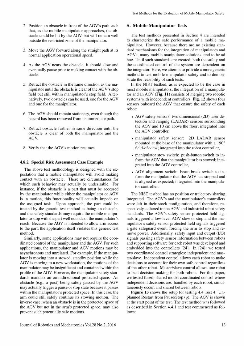
In the NIST testbed, as is expected to be the case inmost mobile manipulators, the integration of a manipula-tor and an AGV (Fig. 11) consists of merging two roboticsystems with independent controllers. Fig. 12 shows foursensors onboard the AGV that ensure the safety of eachrobot:
• AGV safety sensors: two dimensional (2D) laser de-tection and ranging (LADAR) sensors surroundingthe AGV and 10 cm above the floor; integrated intothe AGV controller,
• manipulator safety sensor: 2D LADAR sensormounted at the base of the manipulator with a 190◦field-of-view; integrated into the robot controller,
• manipulator stow switch: push-button switch to in-form the AGV that the manipulator has stowed; inte-grated into the AGV controller,
• AGV alignment switch: beam-break switch to in-form the manipulator that the AGV has stopped andis aligned as expected; integrated into the manipula-tor controller.
The NIST testbed has no position or trajectory sharingintegrated. The AGV’s and the manipulator’s controllerswere left in their stock configuration, and therefore, re-spectively, adhered to the AGV and industrial robot safetystandards. The AGV’s safety sensor protected field sig-nals triggered a low-level AGV slow or stop and the ma-nipulator’s safety sensor protected field signals triggereda gate safeguard event, forcing the arm to stop and re-move power. Additionally, safety input and output (I/O)signals passing safety sensor information between robotsand supporting software for each robot was developed andembedded into the controllers [24]. In [24], we testedtwo coordinated control strategies: independent and mas-ter/slave. Independent control allows each robot to makedecisions to account for their own safe control regardlessof the other robot. Master/slave control allows one robotto lead decision making for both robots. For this paper,we tested fused, shared model coordinated control whereindependent decisions are: handled by each robot, simul-taneously occur, and shared between robots.
Figure 13 shows the setup for testing 4.4 Test 4: Un-planned Restart from Pause/Stop (q). The AGV is shownat the start point of the test. The test method was followedas described in Section 4.4.1 and test commenced as fol-lows:
Journal of Robotics and Mechatronics Vol.28 No.2, 2016 13

Marvel, J. A. and Bostelman, R.
A B
C D
Fig. 11. Series of snapshots from a mobile manipulator test video showing shared model robot coordination. The AGV is movingfrom left to right in (A) and (D) as indicated by the white arrows.
Fig. 12. NIST mobile manipulator testbed showing onboardsafety sensors.
1. The AGV was programmed to move forward alonga straight path between two points, with the arm ex-tended to the right beyond the AGV’s width. Thearm was active, but stationary.
2. An obstacle was positioned to be just to the rightedge of the AGV and within the AGV safety sensorstop field of view. The obstacle was a standard verti-cal cylinder test piece that was well below the manip-ulator safety sensor field of view. A second obstacle,a cardboard cutout of a human, was placed besidethe test piece, outside of the AGV sensor range, yetinside the manipulator sensor range.
3. The AGV was programmed to move along the pathat 1 m/s.
4. Upon detection of the standard test piece, the AGVstopped prior to making contact with the obstacle.
5. The test piece was removed from the AGV safety
sensor detection zone. The cardboard cutout re-mained within the manipulator’s stop field.
6. As expected, the AGV remained stationary, eventhough the hazard was removed from its path.
7. The cardboard cutout obstacle was then moved untilit was clear of both the manipulator and the AGV.
8. The AGV’s motion resumed.
Shared control was needed to accomplish the task, al-though independent control was needed for the decisionsmade by each robot. For example, if the AGV con-troller detected an obstacle in its path, it caused the AGVto stop and also the manipulator to stop. The opposite,manipulator-to-AGV, information was similarly shared.
Test results demonstrated that shared, yet independentcontrol of each robot is effective for this scenario. Fig. 11shows a series of snapshots from a video recording of oneof three duplicate tests. The figure shows the followingresults:
Figure 11(A) the AGV was heading towards a standardobstacle (black cylinder) to the AGV and obstacle to themanipulator (human form cut-out).
Figure 11(B) the AGV safety sensor detected the ob-stacle in the path and stopped. Simultaneously, the obsta-cle to the manipulator (human form cut-out) was detectedby the manipulator safety sensor.
Figure 11(C) the obstacle was removed and the AGVbegan control to move as indicated by the yellow lightsbeing illuminated. However, as shown in the picture, thereis a red light illuminated on the manipulator safety sensorindicating that it detected an obstacle (human-form cut-out), the sensor inputs the information to the manipulatorand in turn, informs the AGV to not move until the obsta-
14 Journal of Robotics and Mechatronics Vol.28 No.2, 2016

Test Methods for the Evaluation of Mobile Manipulator Safety
Fig. 13. The NIST mobile manipulator consists of a 7 DOFindustrial robot arm mounted on top of an omnidirectionalforklift AGV.
cle is removed from the manipulator safety sensor field ofview.
Figure 11(D) as shown in the inset picture, a green lightis illuminated on the manipulator safety sensor indicatingthat it no longer detects an obstacle, the sensor inputs theinformation to the manipulator and in turn, informs theAGV that it can move. The AGV yellow lights indicatethat the AGV is being controlled to move.
Timing and safety field range settings were, as in testresults in [24], viewed as possible instances where theAGV may be too slow to react to possible hazards. Forexample, when the AGV is commanded by the manip-ulator to stop, AGV deceleration combined with manip-ulator safety sensor obstacle detect may be too slow orthe safety field set too short to ensure contact between therobot and obstacle is prevented. In our case, we optimizedthe test based on the current sensor setting placing the ob-stacles to not be contacted since our test considered onlyshared model control. Ideally, as in ANSI/ITSDF B56.5,the AGV is programmed with a controlled braking stopmethod to account for the variability in obstacle detectioncircumstances. Controlled braking allows AGV decelera-tion to be variable, dependent upon safety sensor obstacledetection, so that the AGV can preplan to slow and thenstop before contacting the obstacle.
Test results as compared to metrics proved the follow-ing:
1. Separation Metric:Figure 14 shows a dimensioned drawing of one of the
test setups and distances between the AGV and manipu-lator to a cardboard cutout of a human where several testswere performed. The nearest separation distance to theAGV is approximately 707 mm.
The distance is within the 850 mm metric describedin [3] although the cutout was not struck by the manip-ulator since the AGV could stop within a shorter dis-tance than 850 mm at the 1 m/s velocity. According toANSI/ITSDF B56.5, so long as the obstacle is detectedand not struck by the vehicle frame (or in this case, thefixed robot arm), the test passes. Several (approximately10) iterations were completed where adjustments to thesafety sensor detection range was increased and decreased
Fig. 14. Dimensional drawing of the test setup.
and retested such that, for various vehicle speeds, anystopping distance within the maximum safety sensor de-tection range could be performed. Therefore, we concludethat the separation distance is highly dependent upon thevehicle, safety sensor, and test piece and passes the test,so long as the test pieces are not contacted by either theAGV or manipulator.
2. Functional Stopping Metric:The mobile manipulator came to a controlled stop upon
sensing the B56.5 test piece and the cardboard cutout inall tests. Moreover, when the test piece was removed andthe cardboard cutout not moved, the AGV attempted tomove showing flashing startup lights. However, no mo-tion was detected since the manipulator safety sensor con-tinued to detect the cutout. When the cutout was removed,the AGV resumed motion in the original forward direc-tion.
3. Human Detection and Artifacts:The cardboard cutout and ANSI/ITSDF B56.5 vertical
test piece were used as artifacts to be detected by the AGVand manipulator safety sensors. In every test, these twoartifacts were detected and the vehicle stopped prior tocontacting them with the manipulator or AGV.
6. Discussion
In this paper, we presented test methodologies and met-rics for evaluating the functional safety of mobile manip-ulators. We also provided potential use cases that mayviolate expected safe behaviors. Such cases require thor-ough risk assessments to determine if such contradictorybehaviors should be permitted.
The test was intended to demonstrate feasibility of real,commercial-off-the-shelf robot systems to perform coor-dinated control. The test was also used to validate a pro-posed test method where the authors demonstrated feasi-bility of the proposed Unplanned Restart from Pause/Stop
Journal of Robotics and Mechatronics Vol.28 No.2, 2016 15

Marvel, J. A. and Bostelman, R.
test method. Statistical data from more comprehensivetests could provide increased performance knowledge ofthese robot systems and uncover further robot coordina-tion issues. However, a system (AGV and robot arm) wasused for validation of the proposed generic test method.In order to validate the test method for all systems, othermanufactured systems should also be used to validate thisand all other proposed test methods to ensure expectedsafety performance.
These test methods will be revisited as sensing andsafety capabilities improve, and as safety standards ma-ture and adapt to the state-of-the-art in robotic systemtechnologies. We also expect that standards and improve-ments in mobile manipulator control and performancewill lead to safer and more reliable flexible automationfor the future of smart manufacturing.
References:[1] D. Grubaugh, “Worker killed at Granite City plant,” The Telegraph,
2013.[2] Int. Organization for Standardization (ISO), ISO 13854, Safety of
machinery – Minimum gaps to avoid crushing of parts of the humanbody, 1996.
[3] ISO, ISO 13855, Safety of machinery – Positioning of safeguardswith respect to the approach speeds of parts of the human body,2010.
[4] ISO, ISO 10218-1:2011, Robots and robotic devices – Safety re-quirements – Part 1: Robots, 2011.
[5] ISO, ISO 10218-2:2011, Robots and robotic devices – Safety re-quirements – Part 2: Industrial robot systems and integration, 2011.
[6] American National Standards Institute (ANSI) and Robotics Indus-tries Association (RIA), ANSI/RIA R15.06, Industrial robots androbot systems – Safety requirements, 2012.
[7] ISO, ISO/PDTS 15066, Robots and robotic devices – Industrialsafety requirements – Collaborative industrial robots, unpublished.
[8] ANSI/Industrial Truck Standards Development Foundation(ITSDF), ANSI/ITSDF B56.5, Safety standard for driverless,automatic guided industrial vehicles and automated functions ofmanned industrial vehicles, 2012.
[9] M. Takahashi, T. Moriguchi, S. Tanaka, H. Namikawa, H. Shita-moto, T. Nakano. Y. Minato, T. Ihama, and T. Murayama, “Devel-opment of a Mobile Robot for Transport Application in Hospital,”J. of Robotics and Mechatronics, Vol.24, No.6, 2012.
[10] Y. Kume, Y. Hirata, and K. Kosuge, “Object Handling by Coor-dinated Multiple Mobile Manipulators Without Force/Torque Sen-sors,” J. of Robotics and Mechatronics, Vol.20, No.3 pp. 394-402,2008.
[11] J. Marvel and R. Bostelman. “Towards mobile manipulator safetystandards,” Proc. IEEE Int. Conf. Rob. Sensors Env., pp. 31-36,2013.
[12] P. M. Moubarak and P. Ben-Tzvi, “Adaptive manipulation of a hy-brid mechanism mobile robot,” Proc. IEEE Int. Symp. Rob. Sens.Env., pp. 113-118, 2011.
[13] E. Messina and A. Jacoff, “Performance standards for urbansearch and rescue robots,” Proc. SPIE, Unmanned Syst. Tech. VIII,Vol.6230, 2006.
[14] T. L. Chen and C. C. Kemp, “Lead me by the hand: Evaluation ofa direct physical interface for nursing assistant robots,” Proc. 5thACM/IEEE Int. Conf. Human-Rob. Interact, pp. 367-374, 2010.
[15] S. S. Srinivasa et al., “Herb 2.0: Lessons learned from developinga mobile manipulator for the home,” Proc. IEEE, Vol.100, No.8,pp. 2410-2428, 2012.
[16] European Parliament, “Directive 2006/42/EC of the European Par-liament and of the council of 17 May 2006 on machinery, andamending Directive 95/16/EC,” Official J. of the European Union,L 157, pp. 24-86, 2006.
[17] British Standards Institution, BS EN 1525 Safety of industrialtrucks – Driverless trucks and their systems, 1998.
[18] R. Bostelman, R. Norcross, J. Falco, and J. Marvel, “Develop-ment of standard test methods for unmanned and manned indus-trial vehicles used near humans,” Proc. SPIE Defense, Secur., andSens.: Multisens., Multisource Inf. Fusion: Archit., Algorithms,and Appl., 2013.
[19] J. Rehg, “Introduction to Robotics: A Systems Approach,” PrenticeHall, Inc., 1985.
[20] “BG/BGIA risk assessment recommendations according to ma-chinery directive: Design of workplaces with collaborative robots,U001/2009e October 2009 edition,” BGIA, 2011.
[21] J. Fryman and B. Matthias, “Safety of Industrial Robots: FromConventional to Collaborative Applications,” Proc. 7th. Int. Conf.Safety Indust. Autom. Syst., pp. 198-203, 2012.
[22] ISO, ISO 9283, Manipulating industrial robots – Performance cri-teria and related test methods, 1998.
[23] J. Falco, J. Marvel, and R. Norcross, “Collaborative robotics: Mea-suring blunt force impacts on humans,” Proc. 7th Int. Conf. SafetyInd. Autom. Sys., pp. 186-191, 2012.
[24] R. Bostelman and J. Marvel, “Control Fusion for Safe Multi-robotCoordination,” Proc. SPIE.DSS Defense and Security, Baltimore,MD, 2014.
Name:Jeremy Marvel
Affiliation:National Institute of Standards and Technology
Address:100 Bureau Dr., Stop 8230, Gaithersburg, MD 20899, USABrief Biographical History:2003 Received Bachelor’s in Computer Science from Boston University2005 Received Master’s in Computer Science from Brandeis University2010 Received Ph.D. in Computer Engineering from Case WesternReserve University2010-2011 Adjunct Professor, Akron University2011-2012 Institute for Research in Engineering and Applied Physics,University of Maryland, College Park2012-present Project Leader and Research Scientist, Intelligent SystemsDivision, National Institute of Standards and Technology (NIST)Main Works:• intelligent and adaptive solutions for robot applications, with particularattention paid to human-robot collaborations, multi-robot coordination,safety, perception, and automated parameter optimization
Name:Roger Bostelman
Affiliation:National Institute of Standards and Technology
Address:100 Bureau Dr., Stop 8230, Gaithersburg, MD 20899, USABrief Biographical History:1978-present National Institute of Standards and Technology1987 Received B.S. in Electrical Engineering from the GeorgeWashington University1997 Received M.S. in Tech. Management from University of Maryland,University College2014-present Chairman of ASTM Committee F452015-present Seeking Ph.D. in Computer Science, University ofBourgogneMain Works:• design, building, and testing of mechanical systems and their interfaceelectronics on robot cranes, robot arms, and autonomous vehiclesincluding the RoboCrane, HLPR (Home Lift, Position, and Rehabilitation)Chair, and several other technologies
16 Journal of Robotics and Mechatronics Vol.28 No.2, 2016