Test equipment for physical layer conformance testing of parallel buses exemplified for SFI-4/5...
14
Test equipment for physical layer conformance testing of parallel buses exemplified for SFI-4/5 Interoperability Working Group OFC Atlanta, March 23-28, 2003 Michael Fleischer-Reumann Agilent Technologies
-
Upload
austin-lawson -
Category
Documents
-
view
216 -
download
2
Transcript of Test equipment for physical layer conformance testing of parallel buses exemplified for SFI-4/5...
Test equipment for physical layer conformance testing of parallel buses
exemplified for SFI-4/5
Interoperability Working Group OFC Atlanta, March 23-28, 2003
Michael Fleischer-ReumannAgilent Technologies
Agenda
1. Motivation
2. Location within the system architecture of parallel buses specified by OIF and their architectural parameters
3. General measurement setup to prove SFI-4/5 compliance
4. Focus on timing measurements on SFI-4/5 I/OsSFI-4 output timingSFI-5 output timingSFI-4/5 input timing
5. Specific SFI-5 - item: Jitter and Wander (common and relative)
6. Parallel test equipment: Agilent ParBERT 81250 Platform
7. Summary

Motivation Interoperability – how to demonstrate it?
• Let modules of different vendors work together as demonstrated at the booth
Interoperability – how to assure it?• Let modules of different vendors work together
under corner cases or marginal conditions!• But usually those can not be achieved with
regular modules!• Consequently use test equipment
• for input ports: to generate corner cases according to specifications (e.g. marginal input timing)
• for output ports: check that specified limits are met
to measure the compliance with specifications published in implementation agreements
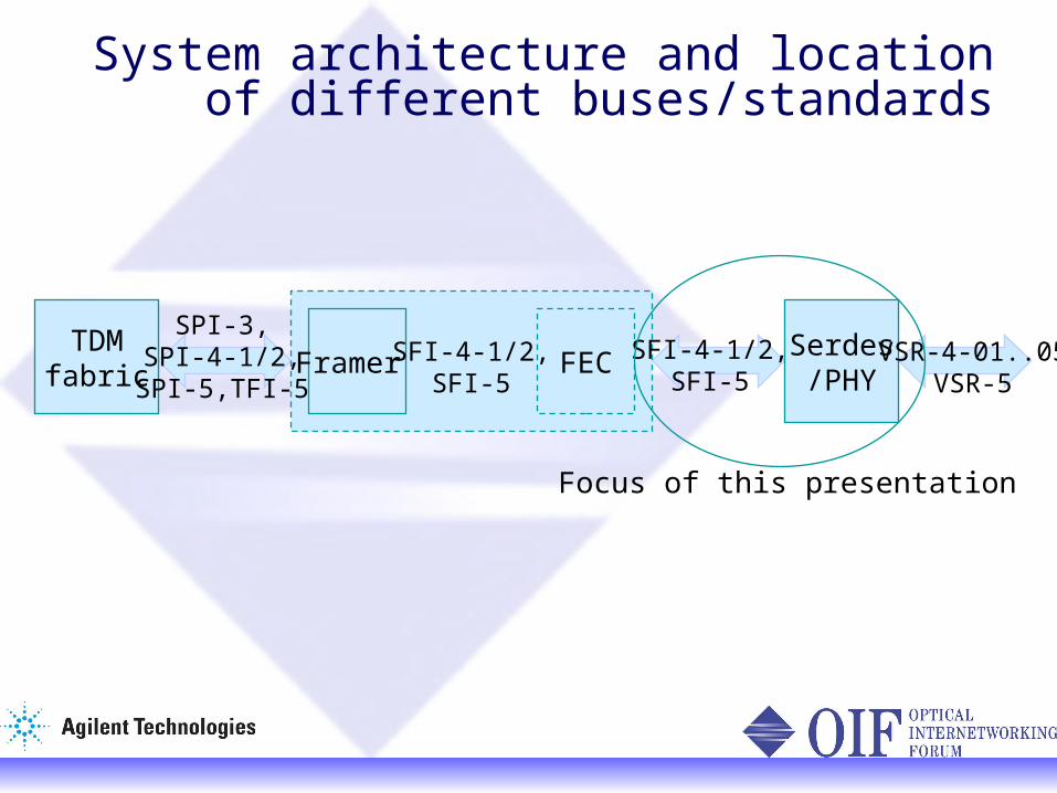
System architecture and location of different buses/standards
TDMfabric FECFramer
Serdes/PHY
SPI-3,SPI-4-1/2,
SPI-5,TFI-5
VSR-4-01..05VSR-5
SFI-4-1/2,SFI-5
SFI-4-1/2,SFI-5
Focus of this presentation

parallel buses specified by OIF (selection)
electrical SFI-4/5 optical VSR-4/5
10Gb/s 40Gb/s 10Gb/s 40Gb/s
SFI-4 SFI-4 phase 2
SFI-5 VSR-4-01 VSR-5
Data channels and rate
16 x diff622Mb/s
4 x diff 2.488...3.125Gb/s
16 x diff 2.488...3.125Gb/s
10 x optical 850nm MM 1.25Gb/s
12 x optical 850nm MM3.318Gb/s
Clock (311) 622MHz
NA 622... 781MHz
NA NA
Other channels
NA NA + Tx/RxDSC Protection & Error Detection Channel (EDC)
NA
Data agnostic
yes yes but:coded and scrambled
Yes but:Deskew signal w/ special data content
No:Sonet cells/frames required
Virtual blocks of EDC shall match SONET frames
A1/B1 bytes boarder used for deskewing
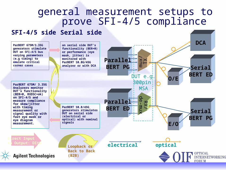
general measurement setups to prove SFI-4/5 compliance
electrical optical
ParallelBERT ED
ParallelBERT PG mux/
TX
RX
/de-m
ux
SerialBERT ED
DCA
O/E
SerialBERT PG
E/O
DUT e.g.300pin
MSA
Serial sideSFI-4/5 side
ParBERT 10.8/45G generators stimulates DUT on serial side (electrical or optical) with nominal signals
ParBERT 675M/ 3.35G Analyzers monitor DUT’s functionality (BER=0, RXDSC=ok) on SFI-4/5 andmeasure compliance for skew/jitter with timing measurement or signal quality with fast eye mask or eye diagram measurement.
on serial side DUT’s functionality (BER=0) or performance (eye mask, jitter) is monitored with ParBERT 10.8G/45G analyzer or with DCA
ParBERT 675M/3.35G generators stimulate DUT on SFI-4/5 bus varying parameters (e.g timing) to emulate critical corner cases
Direct Inputto Output: DItO
Loopback or Back to Back (B2B)

Focus on: Output Timing Measurements (SFI-4)
Specification• Data valid window: UI-400ps
or ts/th=+/-200ps Measurements and results
• BERT-scan:ts/th value and pass/fail, skew between channels
• Fast eye mask:user defined eye mask pass/fail
• Eye diagram
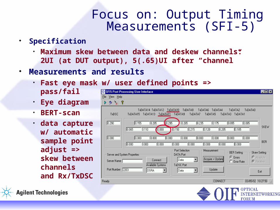
Focus on: Output Timing Measurements (SFI-5)
Specification• Maximum skew between data and deskew
channels: 2UI (at DUT output), 5(.65)UI after “channel”
Measurements and results • Fast eye mask w/ user defined points =>
pass/fail• Eye diagram• BERT-scan• data capture
w/ automaticsample pointadjust =>skew between channels and Rx/TxDSC
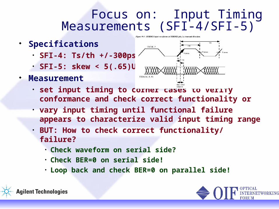
Specifications• SFI-4: Ts/th +/-300ps• SFI-5: skew < 5(.65)UI
Measurement• set input timing to corner cases to verify
conformance and check correct functionality or• vary input timing until functional failure appears
to characterize valid input timing range• BUT: How to check correct functionality/ failure?
• Check waveform on serial side?• Check BER=0 on serial side!• Loop back and check BER=0 on parallel side!
Focus on: Input Timing Measurements (SFI-4/SFI-5)
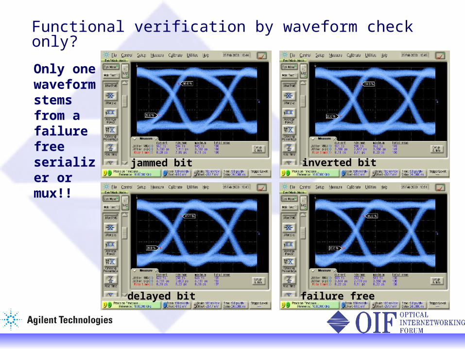
Functional verification by waveform check only?
Only one waveform stems from a failure free serializer or mux!!
failure free
inverted bit
delayed bit
jammed bit

Specific item for SFI-5: HF jitter tolerance
Jitter modulation
inputs
1 : 2poweradder
Eye opening at receiver Pulse or PRBSgenerator
NoiseSource
DJ, (RJ) and TJ are user definable through variable amplitude and frequency simple adjustment to different data rates
ParBERTGenerators D
UT
two ranges: 50 & 500ps/V

range 1: >1.3UI, <120kHz ParBERT in ext. clock mode central clock modulated by
external signal generator
ParBERTGenerators
Specific item for SFI-5: Common plus relative Wander
range 2: <1.3UI, >120kHz ParBERT running at 2.5Gb/s modulate generators with
slightly different frequencies
10MHz ref
f1f1+f
MU
X
Test in two ranges with different setups at discrete frequencies
0.1
10.65
1.3
UI wander
relative
comm
on
f
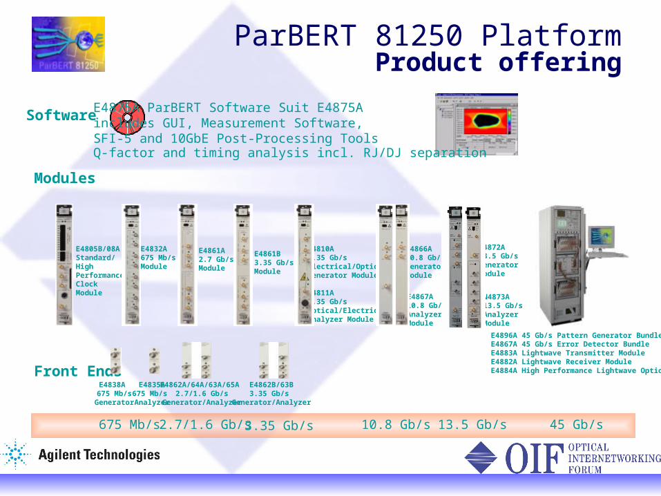
10.8 Gb/s675 Mb/s 2.7/1.6 Gb/s 45 Gb/s3.35 Gb/s
E4805B/08AStandard/HighPerformanceClockModule
E4832A675 Mb/sModule
E4861A2.7 Gb/sModule
E4838A 675 Mb/sGenerator
E4835A675 Mb/s Analyzer
E4862A/64A/63A/65A 2.7/1.6 Gb/s
Generator/Analyzer
E4862B/63B3.35 Gb/s
Generator/Analyzer
E4866A10.8 Gb/sGenerator Module
E4867A10.8 Gb/sAnalyzer Module
E4861B3.35 Gb/sModule
E4810A3.35 Gb/sElectrical/OpticalGenerator Module
E4811A3.35 Gb/sOptical/ElectricalAnalyzer Module
E4896A 45 Gb/s Pattern Generator BundleE4867A 45 Gb/s Error Detector BundleE4883A Lightwave Transmitter ModuleE4882A Lightwave Receiver ModuleE4884A High Performance Lightwave Option
Modules
Front Ends
Software E4875A ParBERT Software Suit E4875A includes GUI, Measurement Software,SFI-5 and 10GbE Post-Processing ToolsQ-factor and timing analysis incl. RJ/DJ separation
13.5 Gb/s
N4872A13.5 Gb/sGenerator Module
N4873A13.5 Gb/sAnalyzer Module
ParBERT 81250 PlatformProduct offering
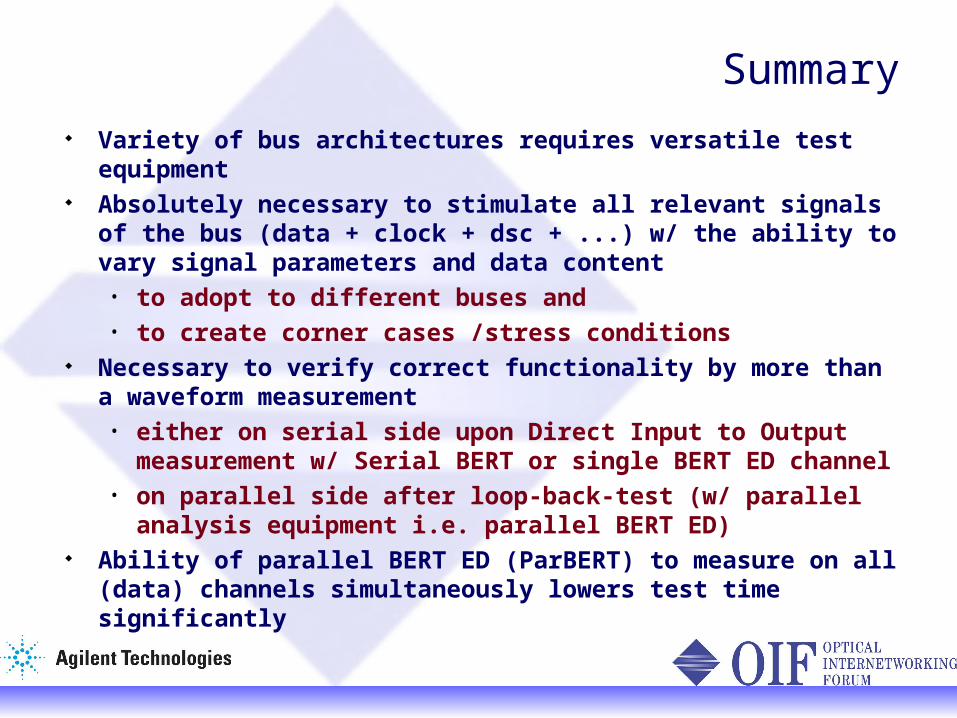
Summary Variety of bus architectures requires versatile test
equipment Absolutely necessary to stimulate all relevant signals of
the bus (data + clock + dsc + ...) w/ the ability to vary signal parameters and data content• to adopt to different buses and • to create corner cases /stress conditions
Necessary to verify correct functionality by more than a waveform measurement • either on serial side upon Direct Input to Output
measurement w/ Serial BERT or single BERT ED channel
• on parallel side after loop-back-test (w/ parallel analysis equipment i.e. parallel BERT ED)
Ability of parallel BERT ED (ParBERT) to measure on all (data) channels simultaneously lowers test time significantly


![Jihad Defined and Exemplified pUpdated]](https://static.fdocuments.net/doc/165x107/577ccff61a28ab9e789107bc/jihad-defined-and-exemplified-pupdated.jpg)