Terrazza Originale Instructions for assembly · Terrazza Originale Instructions for assembly Pent...
104
Terrazza Originale Instructions for assembly Pent roof type A / Gable roof / Head elements / Special shapes Terrazza Originale Instructions for assembly Version 5 12.06.2017 We reserve the right to make technical changes Item number 111361-0000 Page 1/104 English Important notes for retailers/partners and end users Please read carefully before using! These instructions must be kept by the retailer/partner
Transcript of Terrazza Originale Instructions for assembly · Terrazza Originale Instructions for assembly Pent...

Terrazza Originale Instructions for assembly Pent roof type A / Gable roof / Head elements / Special shapes
Terrazza Originale
Instructions for assembly Version 5 12.06.2017
We reserve the right to make technical changes Item number 111361-0000 Page 1/104
English
Important notes for retailers/partners and end users
Please read carefully before using! These instructions must be kept by the retailer/partner

Terrazza Originale
Instructions for assembly Version 5 12.06.2017
We reserve the right to make technical changes Item number 111361-0000 Page 2/104
List of contents
1 Assembly instructions ................................................................................................. 4
1.1 Validity of these instructions ................................................................................................ 4
2 Depiction ....................................................................................................................... 5
2.1 Warnings ............................................................................................................................. 5
2.2 Tips and recommendations ................................................................................................. 5
2.3 Safety instructions ............................................................................................................... 5
2.4 Fundamental safety instructions .......................................................................................... 5
2.5 Qualifications ....................................................................................................................... 6
2.6 Transport ............................................................................................................................. 6
2.7 Fixing material ..................................................................................................................... 6
2.8 Ladders ............................................................................................................................... 6
2.9 Anti-fall guards .................................................................................................................... 6
2.10 Crushing and cutting zones ............................................................................................. 6
2.11 Intended use ................................................................................................................... 7
2.12 Handover ........................................................................................................................ 8
2.13 Functional description ..................................................................................................... 8
2.14 Details on adhesives and sealing compound .................................................................. 8
2.15 Notes on creaking sounds ............................................................................................... 9
2.16 Notes on gutter installation .............................................................................................. 9
2.17 Specifications for drainage of wall bracket ...................................................................... 9
2.18 Unevenness and slopes on the on-site connections ...................................................... 10
2.19 Explanation of symbols ................................................................................................. 11
3 Assembly – Terrazza Originale .................................................................................. 12
3.1 Notes on installing wall bracket + wall bracket glass bead ................................................. 12
3.2 Affixing posts ..................................................................................................................... 16
3.3 Posts set in concrete ......................................................................................................... 19
3.4 Screw foundation system ................................................................................................... 20
3.5 Affixing the aluminium base with the 90 post and 115 post ................................................ 21
3.6 Affixing the roof support ..................................................................................................... 23
3.6.1 Affixing the roof support to the wall bracket ................................................................... 23
3.6.2 Affixing the side roof support ......................................................................................... 24
3.6.3 Affixing the roof support ................................................................................................ 25
3.6.4 Sealing the roof supports to the wall bracket ................................................................. 26
3.7 Affixing the transom + glass butt end ................................................................................. 27
3.8 Fitting the roof covering ..................................................................................................... 28
3.8.1 Special considerations when using glass ...................................................................... 28
3.8.2 Notes on fitting the roof covering ................................................................................... 28
3.8.3 Special considerations when using web plates .............................................................. 30
3.9 Miscellaneous installation notes ........................................................................................ 31
3.9.1 Fitting the side roof support cover strip.......................................................................... 31
3.9.2 Fitting the wall bracket glazing bead ............................................................................. 32
3.9.3 Fitting the leaf guard (optional) ...................................................................................... 33
3.9.4 Installation below the roof overhang .............................................................................. 33
3.10 Affixing posts to a side wall ........................................................................................... 34
3.11 Installation on a side wall .............................................................................................. 35
3.12 Side wall bracket ........................................................................................................... 36
3.13 Wall bracket coupling .................................................................................................... 37
3.14 Gutter coupling.............................................................................................................. 38
3.15 Side-indented posts ...................................................................................................... 39
3.16 Guttering offset ............................................................................................................. 40
3.17 Affixing the roof support to the wall bracket with wall offset ........................................... 41
3.18 Screwing the mounting plates to the roof supports ........................................................ 42
3.19 Installing attachment profiles for glazing elements ........................................................ 43

Terrazza Originale
Instructions for assembly Version 5 12.06.2017
We reserve the right to make technical changes Item number 111361-0000 Page 3/104
3.20 Installing the guttering cover cap ................................................................................... 44
4 Gable roof ................................................................................................................... 45
4.1 Fitting the locking bar ........................................................................................................ 46
4.2 Gutter-to-wall anchorage ................................................................................................... 47
4.3 Fitting the roof support to the corner connector ................................................................. 48
4.4 Fitting the transom to the ridge .......................................................................................... 49
4.5 Fitting the front-mounted guttering wall bracket ................................................................. 50
4.6 Fitting the guttering wall bracket ........................................................................................ 51
4.7 Exploded drawing .............................................................................................................. 53
4.8 Exploded drawing - Options ............................................................................................... 55
5 Installation notes for custom-shaped roofs ............................................................. 57
5.1 Terrazza Type B / Head element Type B ........................................................................... 57
5.1.1 Assembling the kinked side roof support ....................................................................... 58
5.1.2 Fitting the kinked side roof support ................................................................................ 59
5.1.3 Fitting the 135° post ...................................................................................................... 60
5.1.4 Fitting the 135° corner profile ........................................................................................ 62
5.1.5 Fitting the angle bracket shim stop ................................................................................ 65
5.1.6 Sealing the kinked side roof support to the roof covering .............................................. 66
5.1.7 Fitting and sealing the guttering cover cap .................................................................... 67
5.1.8 Sealing, caulking ........................................................................................................... 69
5.1.9 Miscellaneous installation notes .................................................................................... 69
5.2 Terrazza Type N / Head element Type N .......................................................................... 70
5.2.1 Installing the wall bracket support angle ........................................................................ 71
5.2.2 Fitting the gutter corner to a 90° post ............................................................................ 73
5.2.3 Installing the gutter corner and two 180° posts in the corner ......................................... 74
5.2.4 Fitting the roof support to the ridge ................................................................................ 75
5.2.5 Fitting the roof supports 110 (small roof supports) to the roof ridge supports ................ 79
5.2.6 Fitting the stops for the roof covering on the roof ridge supports ................................... 80
5.2.7 Fitting the glazing beads ............................................................................................... 81
5.2.8 Sealing, caulking ........................................................................................................... 82
5.2.9 Miscellaneous installation notes .................................................................................... 83
5.3 Terrazza with angled and partially angled wall bracket ...................................................... 84
5.3.1 Fitting the angled and/or partially angled wall bracket ................................................... 84
5.3.2 Fitting the wall bracket glazing beads ............................................................................ 87
5.3.3 Fitting roof supports to an angled wall bracket .............................................................. 89
5.3.4 Laying the roof covering ................................................................................................ 90
5.3.5 Sealing, caulking ........................................................................................................... 90
5.3.6 Miscellaneous installation notes .................................................................................... 90
5.4 Terrazza with angled or partially angled guttering .............................................................. 91
5.4.1 Fitting angled and/or partially angled guttering .............................................................. 92
5.4.2 Installation of posts ....................................................................................................... 93
5.4.3 Fitting the roof supports to an angled gutter .................................................................. 97
5.4.4 Fitting the stops for the roof covering ............................................................................ 99
5.4.5 Sealing, caulking ......................................................................................................... 100
5.4.6 Miscellaneous installation notes .................................................................................. 100
6 Terrazza Originale exploded drawing ..................................................................... 101
7 Disposal .................................................................................................................... 103
Terrazza Originale
Instructions for assembly Version 5 12.06.2017
We reserve the right to make technical changes Item number 111361-0000 Page 4/104
1 Assembly instructions
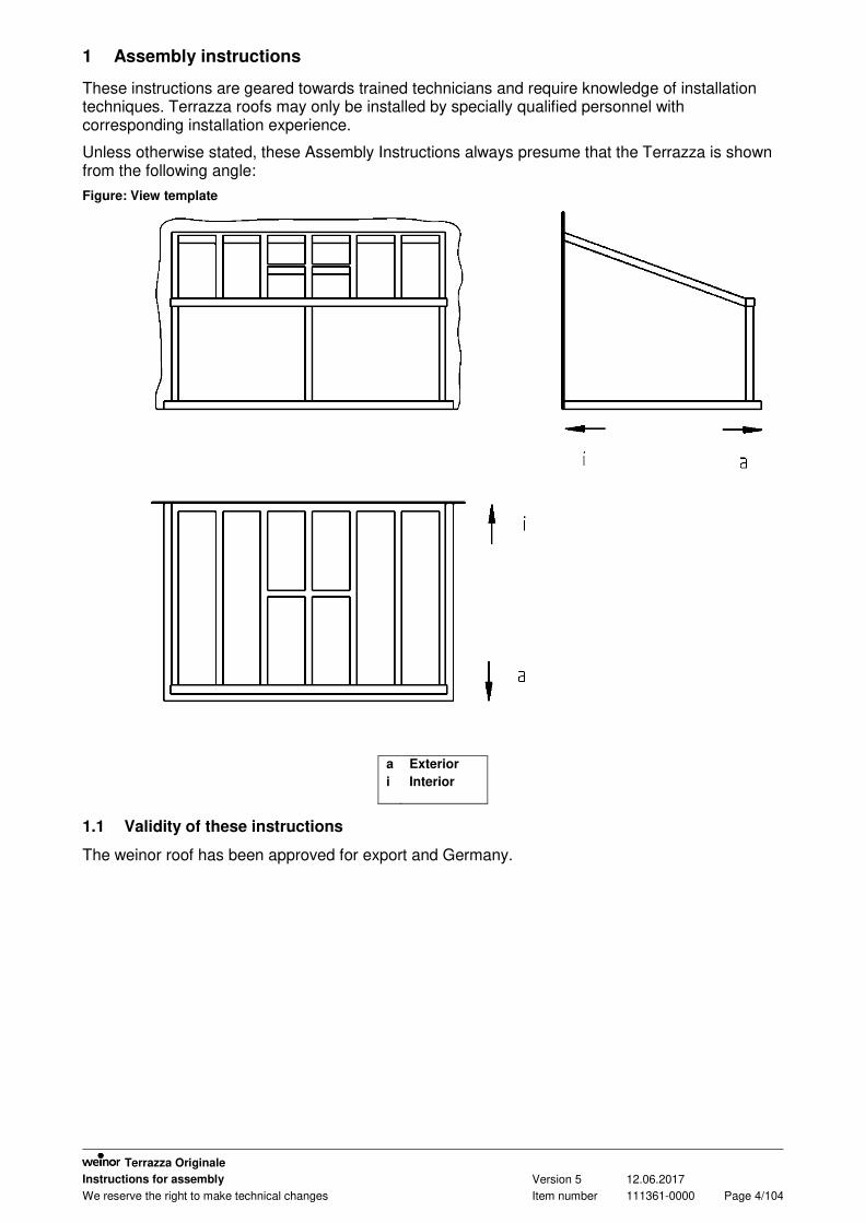
These instructions are geared towards trained technicians and require knowledge of installation techniques. Terrazza roofs may only be installed by specially qualified personnel with corresponding installation experience.
Unless otherwise stated, these Assembly Instructions always presume that the Terrazza is shown from the following angle:
Figure: View template
a
i
Exterior
Interior
1.1 Validity of these instructions
The weinor roof has been approved for export and Germany.

Terrazza Originale
Instructions for assembly Version 5 12.06.2017
We reserve the right to make technical changes Item number 111361-0000 Page 5/104
2 Depiction
2.1 Warnings
The warnings differentiate between personal injury and damage to property. The signal word "Danger" is used for personal injury, and "Caution" for property damage.
Immediate danger to life and limb!
Immediate danger to the product and environment!
2.2 Tips and recommendations
Highlights useful tips and information that enable fast and correct installation.
2.3 Safety instructions
The installation and operating manual must be read and observed. Observe the corresponding accident prevention regulations. Ensure when installing the awning that all existing electrical connections are disconnected. Cordon off a large space around the installation site. Check that all scaffolding and building facilities are duly safe and secure. Observe the stipulations relating to dowels and fixings. Only work with fully intact and appropriate tools. Keep plastic sheeting, packaging material and small parts away from children – risk of
suffocation! For personal safety, it is important that these instructions are complied with. Non-compliance means the manufacturer does not carry any liability. The customer must retain all instructions, and if the product is sold, they must be given to
the new owner.
2.4 Fundamental safety instructions
Personal injury
Risk of personal injury due to improper use of the Terrazza.
Please read and observe the safety instructions contained in this section.
Product and property damage
Risk of damage to the product and property due to improper use of the Terrazza.
Please read and observe the safety instructions contained in this section.
DANGER
IMPORTANT
DANGER
IMPORTANT

Terrazza Originale
Instructions for assembly Version 5 12.06.2017
We reserve the right to make technical changes Item number 111361-0000 Page 6/104
2.5 Qualifications
The instructions for assembly are aimed at qualified technicians who have knowledge of and are experienced in the following areas:
Safety at work, operating safety and accident prevention regulations Use of ladders and scaffolding Handling and transporting long, heavy components Handling and transporting glass panes Handling tools and machines Fitting the fixing materials Estimation of the building structure Start-up and operation of the product If one of these qualifications is lacking, a qualified installation firm must be brought in.
2.6 Transport
The maximum permissible axle loads and gross vehicle weight of the goods vehicles must not be exceeded. Loading a vehicle can alter its handling characteristics. The transported goods must be mounted properly and securely. The packaging of the weinor roof must be protected from moisture. Softened packaging can come loose and cause accidents. Packaging which has been opened for incoming goods inspections must be sealed again properly for further transport. When unloaded, the weinor roof must be carried to the place of installation the right way round so it does not have to be turned round again in a confined space. The instructions on the packaging about which way up the product should be placed must be noted.
2.7 Fixing material
Responsibility for the installation work that is being carried out on-site must always rest with the foreman; it is not possible to issue uniformly applicable instructions due to the differing structural conditions and building regulations that apply at every site. Above all, this implies that all bolts and screws required to affix the weinor roof to the on-site connections (back and side of house wall, concrete base, etc.) must be suitable for the on-site building conditions and the statics requirements.
2.8 Ladders
Do not lean ladders against an unfinished weinor roof. Ladders must be on a firm base and provide adequate support. Only use ladders with adequate load-bearing capacity.
2.9 Anti-fall guards
Workers run the risk of falling when working at elevated heights. Suitable fall protection equipment must be used.
2.10 Crushing and cutting zones
Beware of crushing and cutting zones when installing the roof, e.g. when laying the roof covering, as there is a risk of serious injury.

Terrazza Originale
Instructions for assembly Version 5 12.06.2017
We reserve the right to make technical changes Item number 111361-0000 Page 7/104
2.11 Intended use
Alterations such as attaching items or conversions not envisaged by weinor may only be carried out with weinor's written consent. The type-specific structural standards can also be consulted in order to fit the weinor roof. For a standard snow load of 750N/m², the post must not be any longer than 2.4 m. This means
that the maximum distance from the top of the finished floor to the bottom of the guttering must not exceed 2.4 m.
All supplied profiles and parts (especially posts, roof supports, guttering, transoms, etc.) must be fitted to the roof in accordance with the specifications and must not be omitted.
Important! Please remember that certain areas require the use of laminated sheet glass (LSG). For reasons of structural safety, it is vital that the roof covering is fitted to the roof. The roof structure must therefore never be left to stand alone without the roof covering.
Once the roof has been installed, an additional antifrost hole must be cut through all posts that are to be fitted with drainage. This means that, once the roof is fitted 10 mm to 40 mm above the top edge of the finished floor, a 10 mm hole must be drilled into the front of the post.
Guttering heating can be fitted to help keep the drains from freezing up. Glue on all the screw head caps to prevent them from falling off.
Note: Please also follow all valid DIN standards.
Compliance with any new DIN or EN standards coming into force is also required.
Table: DIN standard
Sealing and gluing jobs must be carried out in accordance with the
following DIN standards:
DIN standard
Energy saving ordinance (Energieeinsparverordnung) EnEV
Wind-tight connections DIN 4108
Sound insulation DIN 4109
Moisture protection DIN 4108
Fire protection DIN 4102
Jointing and caulking DIN 4108 Part 3 Issue: 1981
Application and quality of sealants DIN 1850
Impervious to driving rain DIN 18055 Issue: 1981
Roofing and roof waterproofing DIN 18303
Sealing of joints in external walls using building sealants DIN 18540
Lightning protection VDE 0185
Should national regulations, e.g. building codes of the individual German federal states (Landesbauverordnung (LBO)), require that special regulations or guidelines be followed or lightning protection measures be carried out, these must be put in place. Even if these regulations and guidelines do not require a lightning protection system, we nevertheless recommend that you install one that meets the relevant national standards.

Terrazza Originale
Instructions for assembly Version 5 12.06.2017
We reserve the right to make technical changes Item number 111361-0000 Page 8/104
2.12 Handover
All operating manuals as well as the manufacturer's installation and adjustment instructions for motors, switches and controls must be handed to the user who must be instructed in the operation of the unit. Detailed instruction on the safe and proper operation of the weinor roof must be given. If this is not adhered to and the product is operated incorrectly, the weinor roof may become damaged or accidents could result. The instructions must be kept by the customer and passed on to the new owner if ownership of the weinor roof passes to a third party.
2.13 Functional description
Only high-quality corrosion resistant or anti-corrosion materials are used in weinor roofs. The profiles are made of extruded aluminium. All connecting parts, such as screws, are made of stainless steel. All outside aluminium parts are powder coated.
2.14 Details on adhesives and sealing compound
Recommendations for selecting adhesive and sealing compound: "Takeseal sealant" from Fix-Tec Alternative jointing compounds: Please follow the manufacturer’s guidelines Check on-site whether these are suitable Sealing the on-site circuit points: Choose adhesives and sealants in accordance with the on-site structural conditions Please follow the manufacturer’s guidelines Provision before applying the adhesive and sealant: Clean and prime all parts and surfaces before gluing. If textured paint has been used, sand down the areas to be glued then clean and prime. The gluing/sealing work should only be performed at reasonable temperatures (always follow
the manufacturer’s guidelines for adhesives and sealants). Failure to follow these recommendations may result in: Leakiness in the constructional circuit points a loss in adhesion on certain parts

Terrazza Originale
Instructions for assembly Version 5 12.06.2017
We reserve the right to make technical changes Item number 111361-0000 Page 9/104
2.15 Notes on creaking sounds
The finished product may be prone to creaking as a result of tension in the system's installed parts or also various materials expanding.
2.16 Notes on gutter installation
When installing the guttering, please take the following into account: To prevent the guttering turning away from the glazing elements during its installation or to minimise this effect when laying the roof covering, please install in the following order:
1. Fit the Terrazza 2. Fit the side trapeziums 3. Lay the roof covering 4. Fit the glazing elements
If the guttering is being installed without weinor posts, e.g. on a wall, steps must be taken on-site to prevent the guttering from turning out of position. The guttering must always be handled from below in the region of the post fixation. The guttering should not be supported at the cover cap of the guttering or from above in the region of the cover cap, as otherwise the seal could be damaged, leading to leakiness.
2.17 Specifications for drainage of wall bracket
In the event that the shape of the roof could result in water entering the roof's interior via the wall bracket, the wall bracket components must be sealed on-site to eliminate any chance of water of penetrating here!
This applies to all wall brackets where water cannot be led off to the roof's exterior. For the middle wall bracket on balcony cutouts. For all wall brackets restricted by two walls at the sides. For all wall brackets restricted by a wall and where water cannot be led off to the other
side.

Terrazza Originale
Instructions for assembly Version 5 12.06.2017
We reserve the right to make technical changes Item number 111361-0000 Page 10/104
2.18 Unevenness and slopes on the on-site connections
Any unevenness and slopes on the on-site circuit points must be levelled out on-site. This is necessary to ensure the Terrazza is installed correctly. Possible resources / installation materials for levelling out unevenness: Support blocks Frame wideners
Figure: View of uneven wall from above
1
View from above
Uneven wall

Terrazza Originale
Instructions for assembly Version 5 12.06.2017
We reserve the right to make technical changes Item number 111361-0000 Page 11/104
2.19 Explanation of symbols
In the illustrations shown below on how to install your weinor roof, symbols are used for some installation steps. Please consult the table below for details of what each symbol stands for:
Table: Explanation of symbols
Symbol Explanation Remarks
Seal using appropriate
sealant
See Notes on adhesives and
sealants; order on site or as
optional extras
Seal and firmly tighten all
nuts / screws
On site
Seal using filler cord and a
suitable jointing compound
On site
Firmly tighten nuts / screws On site
Saw component to required
length
On site
Secure roof covering using
glazing packers
On site
Use of pre-compressed
sealing tape
On site
Water drain
Floor or wall

Terrazza Originale
Instructions for assembly Version 5 12.06.2017
We reserve the right to make technical changes Item number 111361-0000 Page 12/104
3 Assembly – Terrazza Originale
3.1 Notes on installing wall bracket + wall bracket glass bead
There are two places where the wall bracket glazing bead can be installed: "top and bottom". Exactly where the wall bracket glazing bead should go depends on the thickness of the roof covering and the roof pitch. Based on the place of installation, different wedge seals will be used. The locations of both the wall bracket glazing bead and the rubber that is to be inserted are indicated on the delivery note supplied. If a sliding skylight is fitted to the wall bracket, the glazing bead wall bracket must be installed and affixed first, followed by the sliding skylight. Figure: Batten
UKW Bottom edge of wall
bracket
(see order confirmation)
Terrazza Originale
Instructions for assembly Version 5 12.06.2017
We reserve the right to make technical changes Item number 111361-0000 Page 13/104
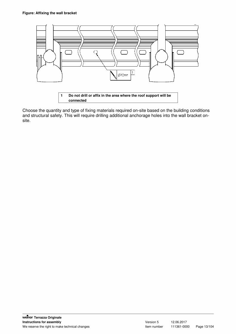
Figure: Affixing the wall bracket
1 Do not drill or affix in the area where the roof support will be
connected
Choose the quantity and type of fixing materials required on-site based on the building conditions and structural safety. This will require drilling additional anchorage holes into the wall bracket on-site.

Terrazza Originale
Instructions for assembly Version 5 12.06.2017
We reserve the right to make technical changes Item number 111361-0000 Page 14/104
Figure: Wall bracket glazing bead
A Wall bracket glazing bead position 1 = bottom
B Wall bracket glazing bead position 2 = top
1 Wedge seal
2 Wall bracket glazing bead
3a Glass
3b Web plate 16 mm

Terrazza Originale
Instructions for assembly Version 5 12.06.2017
We reserve the right to make technical changes Item number 111361-0000 Page 15/104
Figure: Wall bracket
A
B
Uneven facade
Wall bracket
Installation tip for uneven facades: on uneven walls, secure the wall bracket in its intended place; do not tighten the fixing screws; insert the wall bracket glazing bead and affix using e.g. adhesive tape. Now tighten the fixing screws on the wall bracket.

Terrazza Originale
Instructions for assembly Version 5 12.06.2017
We reserve the right to make technical changes Item number 111361-0000 Page 16/104
3.2 Affixing posts
In order to avoid the 90 posts being damaged by frost in winter, an additional Ø10 mm drain hole must be drilled into the posts on site.
This hole is drilled into the front of the 90 posts at around 10 mm to 40 mm above the bottom edge of the finished floor.
The antifrost hole must remain unobstructed, i.e. it must not be concealed by the post plate cover cap.
Figure: Determining the post length
Lp Length of post
UKd Bottom edge of guttering
90 post 115 post
Roof depth Inner edge post
Roof depth Inner edge post

Terrazza Originale
Instructions for assembly Version 5 12.06.2017
We reserve the right to make technical changes Item number 111361-0000 Page 17/104
Figure: Affixing the 90 post
1 Downspout, elbow and rubber optional; saw to length and fit on site
2 Drilled hole to protect against frost damage
3 Screw channels approx. 35mm deep, tap two M8 threads
4 Cover cap for post plate
5 Post plate with holes for attachment to the assembly base and screws
(*) Optional
If no posts are available, the guttering will need to be secured to prevent it from twisting/tipping over
Ø 8
Ø 8,4
WS 13
M8

Terrazza Originale
Instructions for assembly Version 5 12.06.2017
We reserve the right to make technical changes Item number 111361-0000 Page 18/104
Clip profile
Ø 8
Ø 8,4
M8
WS 13
M5x16-
Ø 8
Ø 8,4
WS 13
M8
Clip profile
Figure: Affixing the 115 post
Note: It is possible to selectively bend the clip profile up if it is too loose.
WS 4

Terrazza Originale
Instructions for assembly Version 5 12.06.2017
We reserve the right to make technical changes Item number 111361-0000 Page 19/104
3.3 Posts set in concrete
Note: Applies to the 90 post and 115 post Saw posts to length if required The posts will need to be machined on site to ensure that they cannot be removed from the
foundations. There are various ways of doing this, which can also be combined: On the underside of the 90 post, tap two M8 threads 35 mm deep into the screw
channels and insert screws. Insert screws into the holes on the side of the posts Drill several holes into the side of the posts (at least 13 mm in diameter to allow the
concrete to flow into the posts). Before inserting the posts into the foundations, they will need to be treated with an anti-
corrosion coating. Protective coatings containing chromates or silicate are suitable for this purpose, but adhesive bitumen paint also works.
Then insert the posts into the holes in the foundations; do not set the posts in concrete at this point but simply secure them so that they can be aligned during the installation.
Only after the roof has been fully installed and aligned can the posts be set in concrete in the foundations.
Figure: Setting the posts in concrete
A Trim the posts with stiffeners on site, taking the depth of the concrete encasing into account
B Bucket foundation

Terrazza Originale
Instructions for assembly Version 5 12.06.2017
We reserve the right to make technical changes Item number 111361-0000 Page 20/104
3.4 Screw foundation system
Note: The Krinner company will install the screw foundation system Figure: Krinner screws + plates
Ø 1
3
M1
2x6
0
M12x40
M1
2
M1
2
90 post 115 post
M1
2x6
0
Ø 1
3
M1
2x4
0
M1
2
M1
2

Terrazza Originale
Instructions for assembly Version 5 12.06.2017
We reserve the right to make technical changes Item number 111361-0000 Page 21/104
3.5 Affixing the aluminium base with the 90 post and 115 post
Figure: Aluminium base fixing with 90 post
X Area where post can be affixed to the aluminium base from the back
Z Position of the downspout if a water drain is built into the post. Take care not to damage the downspout
when attaching the screws.
Lep Length of plug-in unit profile
Y Screws fitted on site; number and type of screws depends on on-site conditions
M8x40
M8x40
WS 5
WS 5

Terrazza Originale
Instructions for assembly Version 5 12.06.2017
We reserve the right to make technical changes Item number 111361-0000 Page 22/104
Alternative with 90 post:
Figure: Aluminium base fixing with 115 post
X Area where post can be affixed to the aluminium base from the back
Z Position of the downspout if a water drain is built into the post. Take care not to damage the
downspout when attaching the screws.
Lep Length of plug-in unit profile
Y Screws fitted on site; number and type of screws depends on on-site conditions
WS 5
WS 5
M8x40
M8x40
6.3x50
Y

Terrazza Originale
Instructions for assembly Version 5 12.06.2017
We reserve the right to make technical changes Item number 111361-0000 Page 23/104
3.6 Affixing the roof support
3.6.1 Affixing the roof support to the wall bracket
Figure: Affixing the roof support to the wall bracket
A Dubo retaining ring M5
M5
WS 8

Terrazza Originale
Instructions for assembly Version 5 12.06.2017
We reserve the right to make technical changes Item number 111361-0000 Page 24/104
3.6.2 Affixing the side roof support
Figure: Affixing the side roof support
If required, a screw can be added to affix the cover cap.
M5
WS 8
3.9x13
4.2x25

Terrazza Originale
Instructions for assembly Version 5 12.06.2017
We reserve the right to make technical changes Item number 111361-0000 Page 25/104
3.6.3 Affixing the roof support
Mask the top and bottom web plates using aluminium adhesive tape. Top profile, web plates and glass not supplied. The top profile for the glass must be installed behind the stop; remove the rubber to do so.
Figure: Affixing the roof support
A Dubo retaining ring M5
M5
WS 8
4.2x25

Terrazza Originale
Instructions for assembly Version 5 12.06.2017
We reserve the right to make technical changes Item number 111361-0000 Page 26/104
3.6.4 Sealing the roof supports to the wall bracket
To ensure that no water can penetrate between the roof support and the wall bracket, each roof support must be sealed all the way round the area joined to the wall bracket!
Figure: Sealing the roof supports to the wall bracket

Terrazza Originale
Instructions for assembly Version 5 12.06.2017
We reserve the right to make technical changes Item number 111361-0000 Page 27/104
3.7 Affixing the transom + glass butt end
Before masking with aluminium foil tape, clean the edges of the glass panes using acetone.
Figure: Affixing the transom and glass butt end
A Clean the edges of the glass panes using acetone; mask the glass butt end using alum. foil tape
B Pierce the aluminium foil tape before attaching the top profile of the transom
X Thickness of roof covering
Glue the mounting shoe to the rubber glass support
DIN7991 X
M5x16 10 mm
M5x20 12 mm, 16 mm
Ø 5
M5
M5

Terrazza Originale
Instructions for assembly Version 5 12.06.2017
We reserve the right to make technical changes Item number 111361-0000 Page 28/104
3.8 Fitting the roof covering
3.8.1 Special considerations when using glass
Depending on the roof covering, silicone-free or siliconised seals may be used. If fitting self-cleaning glass: do not allow the glass to come into contact with silicone as it will
impair the self-cleaning effect. Fitters must wear silicone-free clothing (e.g. appropriate trainers if walking over the roof) Avoid using silicone-based sealants near the glass surfaces (e.g. silicone is used to seal
the wall bracket to the wall. As rain washes over the seal and onto the glass, it takes silicone particles with it which deposit on the glass)
If parts become hard to move during the installation work, moisten the seal with some silicone spray or washing-up liquid; never use silicone spray on self-cleaning glass.
3.8.2 Notes on fitting the roof covering
Always follow the manufacturer's guidelines when fitting the roof covering. These include: Guidelines on machining (e.g. trimming) Guidelines on padding and securing Guidelines on thermal expansion Compatibility with adjoining materials (seals) Guidelines on maximum size and loading capacity
The following recommendations do not pretend to be full and complete: Secure the roof covering to prevent it from sliding excessively to the side. Leave enough play if using spacer blocks (take thermal expansion of roof covering into
account). Secure the spacer blocks to prevent them from slipping.
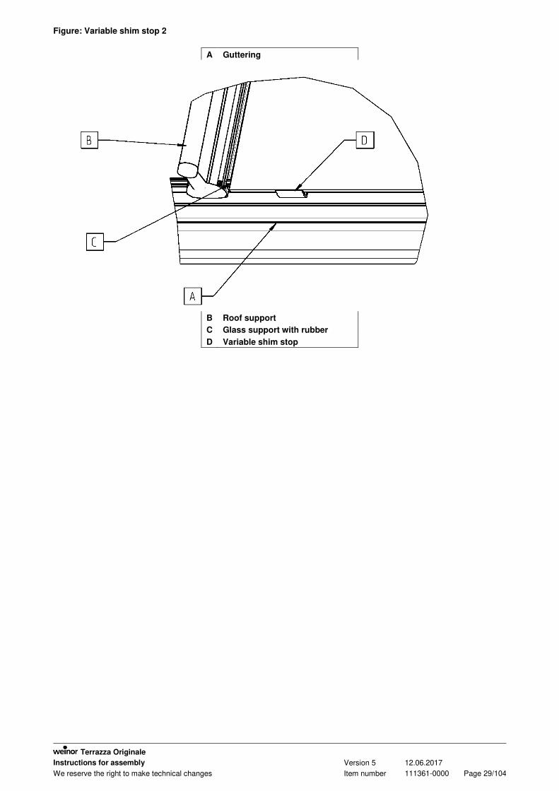
On rectangular roof panels a variable shim stop must be fitted in the middle of each panel if the roof is pitched at > 15 degrees.
Figure: Variable shim stop
Terrazza Originale
Instructions for assembly Version 5 12.06.2017
We reserve the right to make technical changes Item number 111361-0000 Page 29/104
Figure: Variable shim stop 2
A Guttering
B Roof support
C Glass support with rubber
D Variable shim stop

Terrazza Originale
Instructions for assembly Version 5 12.06.2017
We reserve the right to make technical changes Item number 111361-0000 Page 30/104
3.8.3 Special considerations when using web plates
We recommend that you use polycarbonate web plates with the vertical plates spaced no more than 20 mm apart.
When trimming, ensure that you leave at least 10 mm (see sketch) as the rubber wedges will otherwise fit loosely over the pates and could easily be pushed out; trim the plate on both sides if necessary.
Figure: Multi-wall sheets and glass
1 Insert spacer blocks and secure in place to prevent
them from slipping
Depending on the roof covering, silicone-free or siliconised seals may be used.

Terrazza Originale
Instructions for assembly Version 5 12.06.2017
We reserve the right to make technical changes Item number 111361-0000 Page 31/104
3.9 Miscellaneous installation notes
3.9.1 Fitting the side roof support cover strip
Position the side roof support cover strip on the roof support as shown in the drawing. Using your hand or a rubber mallet, tap on the cover plate from above (see direction of arrow);
this will cause the cover strip to lock in place.
Figure: Fitting the cover strips to the roof supports
Figure: Fitting and removing the roof support cover strips

Terrazza Originale
Instructions for assembly Version 5 12.06.2017
We reserve the right to make technical changes Item number 111361-0000 Page 32/104
3.9.2 Fitting the wall bracket glazing bead
On the roof support 150 (Terrazza L), the wall bracket glazing bead must be inserted at an angle between the roof supports and then turned so it is parallel to the wall bracket to leave room to work past the thicker ball-shaped section of the roof support (see drawing).
Insert and rotate the wall bracket glazing bead into the correct groove on the wall bracket as shown in the drawing.
Secure the glazing bead in place using a wedge seal.
Figure: Fitting the glazing bead
A B
C
Wall bracket Roof support 150
Wall bracket glazing bead

Terrazza Originale
Instructions for assembly Version 5 12.06.2017
We reserve the right to make technical changes Item number 111361-0000 Page 33/104
3.9.3 Fitting the leaf guard (optional)
Squeeze the leaf guard and insert it into the guttering from above.
Figure: Fitting the leaf guard
3.9.4 Installation below the roof overhang
Fix the top section of the wall bracket to the wall bracket (see drawing). Insert the roof support. Slide the top section of the wall bracket onto the roof support. Screw the top section of the wall bracket onto the wall bracket. If the wall bracket protrudes to the side of the roof overhang, this end will need to be sealed.
Figure: Installation below the roof overhang

Terrazza Originale
Instructions for assembly Version 5 12.06.2017
We reserve the right to make technical changes Item number 111361-0000 Page 34/104
3.10 Affixing posts to a side wall
When fitting the posts to the wall, the posts are fitted to the substrate using the wall-mounting post plate.
Figure: Affixing posts to a side wall
23 24
(*)
90 post: right wall-mounting post plate cover cap 115 post centre / wall-mounting post plate cover cap 90 post: right wall-mounting post plate with screws 115 post: centre / wall-mounting post plate
Optional

Terrazza Originale
Instructions for assembly Version 5 12.06.2017
We reserve the right to make technical changes Item number 111361-0000 Page 35/104
3.11 Installation on a side wall
If the roof abuts against a wall at one side, the gutter cover plate will need to be screwed onto the gutter before fitting the gutter with posts.
Before the roof support can be fitted, the wall cover plate will need to be screwed onto the roof support and sealed along the side of the roof support.
Once the roof support and the side wall bracket have been fitted, the roof support and guttering will need to be sealed along the side facing the wall.
Trim the profiles on-site where the side wall bracket and the wall bracket meet at the rear wall.
Figure: Installation on a side wall
25 Screwing the plate to the roof support prior to fitting the roof support
4.2x16
4.2x16

Terrazza Originale
Instructions for assembly Version 5 12.06.2017
We reserve the right to make technical changes Item number 111361-0000 Page 36/104
3.12 Side wall bracket
If you have a side wall bracket, the roof will need to be sealed on-site along the wall.
Figure1: Side wall bracket
1 Sealing the plastic profile joints on-site
2 Apply butyl tape between the roof support and the wall bracket
3 Seal all around the wall cover plate
(*) Optional

Terrazza Originale
Instructions for assembly Version 5 12.06.2017
We reserve the right to make technical changes Item number 111361-0000 Page 37/104
3.13 Wall bracket coupling
Thoroughly seal the coupling joint to ensure that water cannot enter the interior.
Figure: Wall bracket coupling
1 Coupling joint on wall bracket profiles
2 If coupling wall bracket profiles, the roof support does not necessarily need to be situated at the coupling
joints
3 Location of the clamping slider in the wall bracket

Terrazza Originale
Instructions for assembly Version 5 12.06.2017
We reserve the right to make technical changes Item number 111361-0000 Page 38/104
3.14 Gutter coupling
Connect the guttering to the coupling profile and caulk. Then place the gutter onto the post and screw in place.
Figure: Gutter coupling
1 Guttering
2 Post
Ø 8
Ø 8,4

Terrazza Originale
Instructions for assembly Version 5 12.06.2017
We reserve the right to make technical changes Item number 111361-0000 Page 39/104
3.15 Side-indented posts
The gutter coupling profile must be slid into the guttering before the cap can be glued on above all side-indented posts.
The post is affixed to the guttering and the guttering coupling profile.
Figure: Side-indented posts
4.2x16
90 post
115 post
Ø 8
Ø 8,4
4,2x25

Terrazza Originale
Instructions for assembly Version 5 12.06.2017
We reserve the right to make technical changes Item number 111361-0000 Page 40/104
3.16 Guttering offset
Figure: Guttering offset
1 Cover cap, WS10
2 Cover cap, WS6
3 Clamp. slider 60x8x3
4 Corner connector for roof support
5 Striker plate for corner connector
6 Disc DIN 9021-5.3-A2
7 Disc DIN 9021-6.4-A2
8 Hex socket head screw ISO 4017-M5x16-A2-70
9 Hex socket head screw ISO 4017-M6x20-A2-70
A The striker plate must always be fitted in such a way that the short
edges of the drilled holes ALWAYS point upwards and outwards!
Check the drill hole positions!
B Steel reinforcement on this side is 100 mm shorter than the gutter

Terrazza Originale
Instructions for assembly Version 5 12.06.2017
We reserve the right to make technical changes Item number 111361-0000 Page 41/104
3.17 Affixing the roof support to the wall bracket with wall offset
Two wall offsets are created as mirror images for the balcony cutout.
Figure: Affixing the roof support to the wall bracket on wall offsets
1 The notches are added to the wall bracket before leaving the factory
2 The notches on the top section of the wall bracket are added on-site

Terrazza Originale
Instructions for assembly Version 5 12.06.2017
We reserve the right to make technical changes Item number 111361-0000 Page 42/104
3.18 Screwing the mounting plates to the roof supports
Select the mounting plates that best suit the roof support in question. Determine where the mounting plates should be fitted onto the roof supports. Align the mounting plates and fix in place using e.g. a C clamp. Drill a 4.8 mm hole through the mounting plates and into the roof support and then screw in
place using self-tapping screws. Be sure not to cause any leaks in the roof support when fitting the mounting plates.
Figure: Screwing the mounting plates to the roof support
1 Support bracket mounting plate for roof support 150
a) Roof support 150
b) Roof support 110
5.5x19 Tx
b) a)

Terrazza Originale
Instructions for assembly Version 5 12.06.2017
We reserve the right to make technical changes Item number 111361-0000 Page 43/104
3.19 Installing attachment profiles for glazing elements
An alternative method for installing the glazing elements is to fit attachment profiles for the 90 posts.
The attachment profiles are fitted to the sides of the 90 posts. The attachment profiles are trimmed to match the length of the 90 posts. At the top end, the attachment profiles will need to be notched on-site to accommodate the
guttering stop. Drill Ø 3.8 mm holes into the 90 posts. Use the attachment profiles as a drilling template. Then screw the attachment profiles in place. Screws should be added approx. every 500 mm. If a gap should remain between the glazing elements and the attachment profiles, this can be
optionally closed using the top profile. Be sure not to damage the 90 posts when installing the attachment profiles and glazing
elements. Note: The attachment profiles are not required with the 115 post.
Figure: Installing attachment profiles for glazing elements
A
B
a)
b)
35
36
27
(*)
90 post in the centre
View from rear
Glazing element with gap towards the attachment profile
Glazing element
Cut a notch in the guttering here
Guttering stop
Top profile
Optional
4,2x16

Terrazza Originale
Instructions for assembly Version 5 12.06.2017
We reserve the right to make technical changes Item number 111361-0000 Page 44/104
3.20 Installing the guttering cover cap
Figure: Installing the guttering cover cap
1
2
3
4
5
Remove the protective film from inside the guttering cover cap.
Affix the guttering cover cap inside to the sides of the guttering and screw on from the outside.
Screw on from inside.
Remove the protective film from one side of the supplied contour sealing compound and stick it on
the outside of the guttering cover cap stud.
Affix the outside of the guttering cover cap to the inside of the guttering cover cap and screw on.
4,2x25
WS 7
WS 7
4,2x16
WS 7
4,2x25
Ø 4
4x16
WS 7

Terrazza Originale
Instructions for assembly Version 5 12.06.2017
We reserve the right to make technical changes Item number 111361-0000 Page 45/104
4 Gable roof
These Assembly Instructions contain features specific to the gable roof only. For all other installation details, please consult the standard assembly instructions for the Terrazza.

Terrazza Originale
Instructions for assembly Version 5 12.06.2017
We reserve the right to make technical changes Item number 111361-0000 Page 46/104
4.1 Fitting the locking bar
Figure: Fitting the locking bar
For information on the front-mounted guttering wall bracket and guttering wall bracket options, please consult the relevant sections.
If taking the guttering wall bracket option, the front and rear locking bars are not used; if taking the front-mounted guttering wall bracket option, the rear locking bar is not used.
Begin by fitting a post as a locking bar between the front two posts on the left and right, and then erect the posts.
Then erect the rear posts. Also use one post here as a locking bar between the posts if this option is being used.
Then affix the guttering to the posts. If using the front locking bar, the round part of the post should be facing the front. If using the rear locking bar (optional), the round part of the post should be facing the rear.
1 Tap 2 x M8 threads approx. 35 mm deep into the screw channels on the both sides of the posts
2 Screw the threads approx. 35 mm deep into both sides of the posts
3 Locking bar
A Front locking bar
B Rear locking bar, optional
v Front
h Rear

Terrazza Originale
Instructions for assembly Version 5 12.06.2017
We reserve the right to make technical changes Item number 111361-0000 Page 47/104
4.2 Gutter-to-wall anchorage
When attaching the gable roof to the wall, always ensure that the roof fits snugly to the wall to prevent the gable roof moving on the building structure. This will require bolting the guttering to the wall on-site using the gutter-to-wall anchorage.
Once the guttering is fitted to the posts, screw the guttering cover plate to the guttering and then seal.
Then affix the guttering to the wall using the gutter-to-wall anchorage. When choosing the screw fittings to attach the gutter-to-wall anchorage to the wall, always take
into account the on-site building conditions.
Figure: Gutter-to-wall anchorage
1 Gutter-to-wall anchorage
2 Wall
3 Screws fitted on-site
A Spacing between guttering and
wall
4,2x16
M6x16

Terrazza Originale
Instructions for assembly Version 5 12.06.2017
We reserve the right to make technical changes Item number 111361-0000 Page 48/104
4.3 Fitting the roof support to the corner connector
Before the roof supports can be screwed together, the clamping sliders for the transoms must first be inserted into the groove on the roof support. When doing this, make sure that the clamping sliders are in the right position.
Coat the front of the roof supports along the ridge with a suitable adhesive and sealant. Slide the roof supports onto the corner connectors and, if necessary, gently tap in place using a
rubber mallet until the two roof supports fit together snugly. Screw the roof support onto the corner connector. Then clean off any residual adhesive and sealant along the joints on the outside of the roof
supports.
Figure: Fitting the roof support to the corner connector
25 Slide the roof support onto the corner connector and affix with screws
26 Once these are connected, clean off any residual adhesive and sealant on the outside of the roof
support
27 Corner connector
28 Clamping slider
29 Tapped hole; facing the ridge
30 Countersunk hole; facing lower end of roof support
M6x30

Terrazza Originale
Instructions for assembly Version 5 12.06.2017
We reserve the right to make technical changes Item number 111361-0000 Page 49/104
4.4 Fitting the transom to the ridge
Screw the transom onto the roof support. Before masking with aluminium foil tape, clean the edges of the glass panes using acetone. Use 80-mm wide aluminium foil tape and cut clean strips. Trim the aluminium concealing tape to the right width if necessary.
Figure2: Fitting the transom to the ridge
1 Cut to match roof pitch
2 Aluminium foil tape
3 Mask the top profile of transom using mirror adhesive tape
M5x8

Terrazza Originale
Instructions for assembly Version 5 12.06.2017
We reserve the right to make technical changes Item number 111361-0000 Page 50/104
4.5 Fitting the front-mounted guttering wall bracket
If the guttering abuts against a wall at the front, the guttering can be affixed to the wall using the guttering angle bracket. The angle bracket is optional.
At this point in time, no posts are used here. The task of bolting the guttering angle bracket to the wall and the guttering is performed on-
site. Bolting to the wall: The appropriate screw fittings must be determined on site based on the state of the building and structural safety requirements. Bolting to the gutter: The holes required to attach the angle bracket to the gutter must be drilled into the gutter on site. To do this, place the guttering against the angle brackets fitted to the wall. Then align the guttering and, using the angle brackets, mark where the holes are to be drilled and drill the holes. When doing this, be sure not to cause any leaks in the gutter.
Figure: Fitting the front-mounted gutter wall bracket
1 Only drill into this area of the gutter; the diameter of the drill holes must match the screws
provided
2 Gutter angle bracket, to be fitted on-site
Cover cap for gutter angle bracket, to be fitted on-site
3 Screws for wall installation; to be selected on-site based on state of building and structural
safety requirements.
4,2x16
5,5x25
M10x30
Terrazza Originale
Instructions for assembly Version 5 12.06.2017
We reserve the right to make technical changes Item number 111361-0000 Page 51/104
4.6 Fitting the guttering wall bracket
If the guttering abuts against a side wall, the guttering can be affixed to the wall using guttering angle brackets. The angle bracket is optional.
At this point in time, no posts are used here. The number of angle brackets with caps must, at a minimum, tally with the number of posts.
The distance between the angle brackets must be no greater than what the distance between the posts would be. The angle brackets are positioned where the posts go.
The drain leading from the guttering is added at the front, next to the guttering angle bracket. The task of bolting the angle bracket to the wall and the guttering is performed on-site. Be sure
not to cause any leaks in the guttering when drilling the holes. The screws required to affix the angle bracket to the wall must be determined on-site based on
the state of the building and structural safety requirements. A bag of screws needed to attach the angle bracket to the gutter is supplied.
First fit the angle brackets to the wall. Then place the gutter against the angle brackets and align. Using the angle brackets, determine where holes need to be drilled to attach the guttering to the angle brackets and then drill the holes into the gutter.
Once this is done, screw the angle brackets onto the gutter. This option can be performed with no additional time and effort if the roof is pitched at no more
than 20° (see Illustration A). If the roof pitch exceeds 20°, the roof supports will need to be adapted on-site (see Illustration
B). In this case, the roof support caps can no longer be used. The roof supports will need to be
covered and sealed on-site.

Terrazza Originale
Instructions for assembly Version 5 12.06.2017
We reserve the right to make technical changes Item number 111361-0000 Page 52/104
Figure: Fitting the gutter wall bracket
1 Roof support adjusted on-site
A Illustration A
B Illustration B

Terrazza Originale
Instructions for assembly Version 5 12.06.2017
We reserve the right to make technical changes Item number 111361-0000 Page 53/104
4.7 Exploded drawing
Figure: Exploded drawing

Terrazza Originale
Instructions for assembly Version 5 12.06.2017
We reserve the right to make technical changes Item number 111361-0000 Page 54/104
Item Designation Item
(untreated) Item (painted) Remarks
1 Guttering cover plate 100429 102177
2 Guttering cover plate for side drain 100435 102180
3 Cover plate for DT150 to wall 100432 102232
4 Cover cap for guttering angle bracket 107850 108051
5 Left-hand guttering cover cap, complete - 120593/ 120594
6 Right-hand guttering cover cap, complete
- 120593/ 120594
7 Cap for roof support 150 109435 109872
8 Cover cap for post plate 108017 108127
9 Side roof support cover strip 116214 116240
10 Top profile 15x20 114926 115080
11 Cover profile 16 mm 101061 102223
12 Left wall-mounting post plate cover cap 108017 108127
13 Right wall-mounting post plate cover cap
108017 108127
14 Aluminium base for post None 102234
15 Post-to-guttering connection 100387 102175
16 Attachment profile for post, 180° 109030 109031
17 Angle bracket for post 101082 None
18 Gutter angle bracket 107851 108052
19 Guttering 101046 102215
20 Universal guttering coupling 109807 None
21 Roof support 150 101038 102207
23 Downspout seal 101057 None
24 Slide-in profile for post, 1500 mm 101172 None
25 Universal complete gable roof corner joint
108482 None
26 53x1.5 downspout 111963 111964
27 53x1.5 downspout coupling 112007 112008
28 Gutter-to-wall anchorage 109666 109667
29 Small base plate for post 116837 116838
30 Glass support 107895 108220
31 Roof support glazing bead 101040 102209
33 Protective leaf grille 113388 None
34 Complete DT150 mounting plate None 101187
35 Post 101048 102217
36 Large, reinforced post plate 101171 102248
37 Post plate for wall 108128 108320
38 Transom 101047 102121
39 Solar cover profile for transom 100892 102202
40 Pipe bend 87° 111870 111871
41 Clamp D53 101123 102233
42 Screw socket, complete None 112061
44 Side wall bracket 108113 101159

Terrazza Originale
Instructions for assembly Version 5 12.06.2017
We reserve the right to make technical changes Item number 111361-0000 Page 55/104
4.8 Exploded drawing - Options
Figure: Front-mounted gutter wall bracket
1 Gutter angle bracket; gutter angle bracket cover cap
2 Screws for wall installation; select on-site
4.2x16
5.5x25
M10x30

Terrazza Originale
Instructions for assembly Version 5 12.06.2017
We reserve the right to make technical changes Item number 111361-0000 Page 56/104
Figure: Gutter wall bracket
1 Screws for wall installation; select on-site

Terrazza Originale
Instructions for assembly Version 5 12.06.2017
We reserve the right to make technical changes Item number 111361-0000 Page 57/104
5 Installation notes for custom-shaped roofs
5.1 Terrazza Type B / Head element Type B
These Assembly Instructions contain features specific to the Type B only. For all other installation details, please consult the standard assembly instructions for the Terrazza.

Terrazza Originale
Instructions for assembly Version 5 12.06.2017
We reserve the right to make technical changes Item number 111361-0000 Page 58/104
5.1.1 Assembling the kinked side roof support
The two parts making up the side roof support will need to be fitted and sealed on-site. Apply a suitable adhesive and sealant to the join between the two parts. Then slide the bottom end of the side roof support over the corner connector and screw the
two roof support parts together.
Figure: Assembling the side roof support
1 Corner connector Slide bottom end of roof support over corner connector
2
M6x20

Terrazza Originale
Instructions for assembly Version 5 12.06.2017
We reserve the right to make technical changes Item number 111361-0000 Page 59/104
5.1.2 Fitting the kinked side roof support
Before fitting the kinked side roof support, check to ensure that the gutter cap has not been fitted to the gutter yet. The gutter cap should only be fitted after the kinked side roof support has been fitted.
The kinked side roof support with attached clamping slider affixes to the wall bracket and guttering.
Before laying the roof covering, make sure that the kinked side roof support is adequately supported underneath the Knick.
This can also be done using the 135° post or 135° corner profile, both of which are available through weinor as optional extras.
Adjust the profiles on-site and screw onto the kinked side roof support and the foundations.
Figure: Fitting the 135° post underneath the side roof support
1 Post, 135 degrees 2 Do not fit the gutter cap before the kinked side roof support has
been fitted

Terrazza Originale
Instructions for assembly Version 5 12.06.2017
We reserve the right to make technical changes Item number 111361-0000 Page 60/104
5.1.3 Fitting the 135° post
Saw the post to length. Align the post to the side roof support and trace the outline of the post on the floor. Using the traced outline, bring the 90x70x7x28 angle bracket into position and affix to the
floor. Position the 135° post over the 90x70x7x28 angle bracket and below the side roof support. Drill into the 135° post and 90x70x7x28 angle bracket and affix (Make sure that you do not
drill into the slotted holes on the angle bracket.). Drill through the side roof support into both 40x40x5x20 angle brackets and affix; apply
sealant to the screws.
Figure: Fitting the 135° post
Attach D12x7 protective caps to all screws that remain visible.
1 Angle bracket 40x40x5x20
2 Angle bracket 90x70x7x28
3 Cover cap D12x7
4.2x16

Terrazza Originale
Instructions for assembly Version 5 12.06.2017
We reserve the right to make technical changes Item number 111361-0000 Page 61/104
Figure: Affixing the 135° post
A Affixing to the side roof support B Affixing to the floor 1 The 135-degree post below the kink should be fitted flush to the
inner surfaces of the side roof support

Terrazza Originale
Instructions for assembly Version 5 12.06.2017
We reserve the right to make technical changes Item number 111361-0000 Page 62/104
5.1.4 Fitting the 135° corner profile
Saw the 135° corner profile to length.
Figure: Fitting the 135° corner profile underneath the side roof support
1 Corner profile, 135 degrees 2 Do not fit the gutter cap before the kinked side roof support has
been fitted

Terrazza Originale
Instructions for assembly Version 5 12.06.2017
We reserve the right to make technical changes Item number 111361-0000 Page 63/104
Option 1:
Position the 135° corner profile below the side roof support and align Drill through the side roof support into the round rod and affix the side roof support to the
round rod; apply sealant to the screws Fit the 90x70x7x28 angle bracket to the outside of the 135° corner profile and affix to the
floor Option 2:
Align the 135° corner profile to the side roof support and trace the outline of the 135° corner profile on the floor
Recess the 90x70x7x28 angle bracket, then position using the traced outline and affix to the floor
Place the 135° corner profile under the side roof support Drill into the side roof support and 135° corner profile and affix; apply sealant to the screws Drill into the 90x70x7x28 angle bracket and the inner face of the 135° corner profile and
affix Attach D12x7 protective caps to all screws that remain visible.
Figure: Fitting the 135° corner profile
V1 Option1 – Affixing the outer 90x70x7x28 angle bracket V2 Option2 – Affixing the inner 90x70x7x28 angle bracket 1 Round rod, D30x60 2 Angle bracket 90x70x7x28 3 Cover cap D12x7
Ø 6
4.2x16
4.2x32

Terrazza Originale
Instructions for assembly Version 5 12.06.2017
We reserve the right to make technical changes Item number 111361-0000 Page 64/104
Figure: Affixing the 135° corner profile
V1 Option1 – Affixing the outer 90x70x7x28 angle bracket V2 Option2 – Affixing the inner 90x70x7x28 angle bracket 1 The 90x70x7x28 angle bracket must be recessed to ensure
that it fits into the 135-degree corner profile (example) 2 Slide the 135-degree corner profile over to the side roof
support stops and fit to the side roof support
If glazing elements are used on the Terrazza, there is no need to attach the 135° corner profile to the 90x70x7x28 angle bracket, provided that the glazing elements are bolted to the floor and the 135° corner section.

Terrazza Originale
Instructions for assembly Version 5 12.06.2017
We reserve the right to make technical changes Item number 111361-0000 Page 65/104
5.1.5 Fitting the angle bracket shim stop
Before installing the roof covering, it is essential that the angle bracket shim stop is fitted to the kinked side roof support.
The items must be fitted in such a way that the angle bracket acts as a stop for the roof covering.
Affix glazing packers between the angle bracket shim stop and the roof covering.
Figure: Shim stop
1 Angle bracket, 20x20x5
2 Clamping slider
Figure: Fitting the shim stop
1 Install glazing packers here before inserting the roof covering
M5x10
M5x10

Terrazza Originale
Instructions for assembly Version 5 12.06.2017
We reserve the right to make technical changes Item number 111361-0000 Page 66/104
5.1.6 Sealing the kinked side roof support to the roof covering
After installing the roof covering, apply aluminium foil tape to the kinked side roof support starting approx. 100 mm above the kink to the gutter.
Make sure that the aluminium foil tape is applied from the roof covering to the roof support to ensure that no water can penetrate.
Figure: Position of aluminium foil tape
1 Aluminium foil tape

Terrazza Originale
Instructions for assembly Version 5 12.06.2017
We reserve the right to make technical changes Item number 111361-0000 Page 67/104
5.1.7 Fitting and sealing the guttering cover cap
After the kinked side roof support has been fitted, slide the guttering cover cap over the guttering and then screw in place.
Also seal the guttering cover cap to the kinked side roof support as well as to the 135° corner profile if provided.
Figure: Fitting the guttering cover cap
On the standard Type B and Type B version with 135° corner profile, be sure to seal the guttering cover cap to the kinked side roof support and/or 135° corner profile.
4.2x25
4.2x16

Terrazza Originale
Instructions for assembly Version 5 12.06.2017
We reserve the right to make technical changes Item number 111361-0000 Page 68/104
Figure: Sealing the guttering cover cap
A Type B with 135-degree post
B Type B with 135-degree corner profile

Terrazza Originale
Instructions for assembly Version 5 12.06.2017
We reserve the right to make technical changes Item number 111361-0000 Page 69/104
5.1.8 Sealing, caulking
When erecting the roof and following completion, seal all areas where water could penetrate into the interior. Always ensure you use appropriate sealants. We recommend:
"Takeseal sealant" from Fix-Tec
The following areas (among others) must be caulked: around the roof supports and wall bracket glazing beads along the wall bracket along the abutting joint between the roof support glazing beads and the wall bracket
glazing beads along the abutting joint between the two roof support sections on the kinked side roof
support
Aluminium foil tape must be applied: from the kinked side roof support to the roof covering
Figure: Sealing the glazing beads
5.1.9 Miscellaneous installation notes
weinor needed the drill holes in the wall bracket in order to construct the roof. The drill holes are not intended to indicate how many mounting holes are actually required on-site or whether the wall bracket can be affixed using the existing drill holes.
Terrazza Originale
Instructions for assembly Version 5 12.06.2017
We reserve the right to make technical changes Item number 111361-0000 Page 70/104
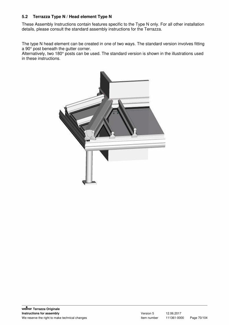
5.2 Terrazza Type N / Head element Type N
These Assembly Instructions contain features specific to the Type N only. For all other installation details, please consult the standard assembly instructions for the Terrazza. The type N head element can be created in one of two ways. The standard version involves fitting a 90° post beneath the gutter corner. Alternatively, two 180° posts can be used. The standard version is shown in the illustrations used in these instructions.

Terrazza Originale
Instructions for assembly Version 5 12.06.2017
We reserve the right to make technical changes Item number 111361-0000 Page 71/104
5.2.1 Installing the wall bracket support angle
A wall bracket support angle must be affixed to the wall bracket at the 90° bend. The task of drilling the holes for the support angle and affixing it is to be done on-site, in line
with the relevant building conditions.
Figure: Fitting the wall bracket support angle
1 Wall bracket support angle, 90 degrees 2 Drill the holes and affix the 90° wall bracket support angle
on-site; the number of fixings and their position must be determined at the site of installation

Terrazza Originale
Instructions for assembly Version 5 12.06.2017
We reserve the right to make technical changes Item number 111361-0000 Page 72/104
Figure: Fitting the 90-degree post plate
1 Cover cap for 90-degree post plate 2 Post plate, 90 degrees 3 Drilled hole to protect against frost damage; only if
draining through the post
Affix the 90° post plate to the 90° post using DIN7991-M8x40 countersunk screws. If using the "drainage through the post" option, drill an additional drainage hole to avoid
frost damage. In this case, please follow the standard assembly instructions.
M8x40

Terrazza Originale
Instructions for assembly Version 5 12.06.2017
We reserve the right to make technical changes Item number 111361-0000 Page 73/104
5.2.2 Fitting the gutter corner to a 90° post
Figure: Installing the roof gutter corner on the post
1 Corner connector 2 Gutter connector
Seal all the way round the joint. To do this, remove the corner connector from the gutter, fit
the gutter to the 90° post, then apply sealant to the corner connector and reinsert into the gutter. Apply a suitable sealant to every abutting joint after each subsequent installation step. Once sealed, the joints should be completely leak-tight.
Attach the 90° gutter connector to the guttering. Affix the guttering to the post and seal. Remove the nuts and washers from the loose ends of the clamps used for tensioning;
remove one of the grub screws from the post to make way for the second section of guttering.
Slide the second section of guttering over the 90° gutter corner connector while also inserting the loose ends of the tensioning clamps into the holes of the support angle.
Affix the guttering to the post and seal. Affix the loose ends of the clamps complete with nuts and washers to the support angles. Remove any excess adhesive and sealant.
Ø 8
Ø 6
M8x50
M6
M8

Terrazza Originale
Instructions for assembly Version 5 12.06.2017
We reserve the right to make technical changes Item number 111361-0000 Page 74/104
5.2.3 Installing the gutter corner and two 180° posts in the corner
Figure: Installing the roof gutter corner on the post
1 Corner connector 2 Gutter connector
Assemble the first section of guttering and the posts. Apply a suitable adhesive and sealant to the guttering and corner connector. Insert the corner connector into the pre-assembled guttering. Affix the 90° gutter connector using a suitable adhesive and sealant. Apply a suitable adhesive and sealant to the mitred part of the second section of guttering. Apply a suitable adhesive and sealant to protruding section of the corner connector. Slide the second section of guttering over the corner connector and insert the kinked
threaded rods used for tensioning into the support angles. Attach the guttering to the posts. Remove any excess adhesive and sealant. Tension the two sections of guttering using the kinked threaded rods and tighten the nuts.
Ø 8
M8x50
Ø 6
M6
M8

Terrazza Originale
Instructions for assembly Version 5 12.06.2017
We reserve the right to make technical changes Item number 111361-0000 Page 75/104
5.2.4 Fitting the roof support to the ridge
Two roof supports need to be fitted to the ridge. Affix both roof supports with attached clamping slider to the guttering and the wall bracket. Glue a cover plate onto the front of the two roof supports where they join and also affix the
cover plate to the shim stops.
Figure: Fitting the front cover plate
1 Front cover plate
4.2x16

Terrazza Originale
Instructions for assembly Version 5 12.06.2017
We reserve the right to make technical changes Item number 111361-0000 Page 76/104
Screw a plate onto the top of the two roof supports and glue in place; affix screws every 500 mm.
Seal the areas around the plate and the roof support as well as the wall bracket. The plate is positioned on the wall bracket below the top sections of the wall bracket.
Figure: Fitting the top cover plate
1 Upper part top section of
wall bracket Figure: Fitting the top section of the wall bracket
1 Top cover plate 2 Cover cap D12x7
4,2x16
4,2x16

Terrazza Originale
Instructions for assembly Version 5 12.06.2017
We reserve the right to make technical changes Item number 111361-0000 Page 77/104
Figure: Sealing the gap between the roof supports
1 Apply butyl tape between the roof supports: secure the drain in the
guttering 2 Stop profile 3 Seal cover plate along entire length of roof support
The gap between the two roof supports must be sealed. To do this, either trim the supplied stop profile to length and then glue to the area below
the roof supports where the two meet or seal the gap using a suitable adhesive and sealant.

Terrazza Originale
Instructions for assembly Version 5 12.06.2017
We reserve the right to make technical changes Item number 111361-0000 Page 78/104
Figure: Fitting the T-shaped cover strip

Terrazza Originale
Instructions for assembly Version 5 12.06.2017
We reserve the right to make technical changes Item number 111361-0000 Page 79/104
5.2.5 Fitting the roof supports 110 (small roof supports) to the roof ridge supports
The roof supports 110 must be attached to the roof supports 150 on the ridge of the roof where corresponding holders have been attached to the roof support 150.
Figure: Location of roof support 110 holder
1 Holder for roof support 110
Affix the roof support 110 to the roof support 150 and seal around the two.
Figure: Affixing the roof support 110
4,2x9,5
4,2x16

Terrazza Originale
Instructions for assembly Version 5 12.06.2017
We reserve the right to make technical changes Item number 111361-0000 Page 80/104
5.2.6 Fitting the stops for the roof covering on the roof ridge supports
Install angle brackets on the roof ridge supports so that they can be used as stops for the roof covering.
Affix glazing packers between the roof covering and the angle brackets.
Figure: Shim stop
1 Angle bracket,
20x20x5 2 Clamping slider
Figure: Fitting the shim stops
1 Install glazing packers here before inserting the roof covering
M5x10
M5x10

Terrazza Originale
Instructions for assembly Version 5 12.06.2017
We reserve the right to make technical changes Item number 111361-0000 Page 81/104
5.2.7 Fitting the glazing beads
First fit the glazing beads to the wall bracket. Then fit the glazing beads to the roof supports.
Figure: Fitting the glazing beads
1 Roof support glazing
bead 2 Wall bracket glazing bead
In the case of the joists, first fit the glazing beads to the roof support 150 and then to the roof support 110.
Figure: Fitting the glazing beads to the joists
1 Glazing bead for roof
support 110

Terrazza Originale
Instructions for assembly Version 5 12.06.2017
We reserve the right to make technical changes Item number 111361-0000 Page 82/104
5.2.8 Sealing, caulking
When erecting the roof and following completion, seal all areas where water could penetrate into the interior. Always ensure you use appropriate sealants.
We recommend: "Takeseal" from Fix-Tec
The following areas (among others) must be caulked:
gutter joints the area where the roof support 110 and roof support 150 join (top and bottom and/or
exterior and interior) the area where the roof support cover plate is joined to the wall brackets below the roof supports on the roof ridge around the roof supports and wall bracket glazing beads along the wall bracket along the abutting joint between the roof support glazing beads and the wall bracket glazing
beads Butyl tape between the roof supports
Aluminium foil tape must be applied:
to the area where the roof support 110 and roof support 150 join
Figure: Position of aluminium foil tape
1 Aluminium foil tape
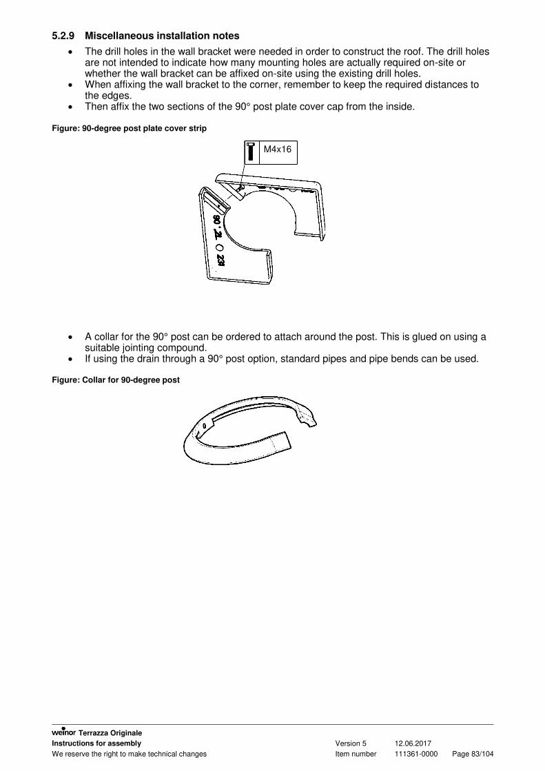
Terrazza Originale
Instructions for assembly Version 5 12.06.2017
We reserve the right to make technical changes Item number 111361-0000 Page 83/104
5.2.9 Miscellaneous installation notes
The drill holes in the wall bracket were needed in order to construct the roof. The drill holes are not intended to indicate how many mounting holes are actually required on-site or whether the wall bracket can be affixed on-site using the existing drill holes.
When affixing the wall bracket to the corner, remember to keep the required distances to the edges.
Then affix the two sections of the 90° post plate cover cap from the inside. Figure: 90-degree post plate cover strip
A collar for the 90° post can be ordered to attach around the post. This is glued on using a suitable jointing compound.
If using the drain through a 90° post option, standard pipes and pipe bends can be used.
Figure: Collar for 90-degree post
M4x16

Terrazza Originale
Instructions for assembly Version 5 12.06.2017
We reserve the right to make technical changes Item number 111361-0000 Page 84/104
5.3 Terrazza with angled and partially angled wall bracket
These Assembly Instructions contain features specific to the angled and partially angled wall bracket. For all other installation details, please consult the standard assembly instructions for the Terrazza.
5.3.1 Fitting the angled and/or partially angled wall bracket
When installing the angled wall bracket, please take the following into account: The roof and angled wall bracket are manufactured to the specifications in the order.
These can only be correctly installed if they match the actual building conditions on-site. If the actual building conditions deviate from the order specifications, fit the angle wall bracket in a way that compensates for the deviations. Installation steps:
Align the sides and the height of the wall bracket. To do this, make sure that, on roofs without a side wall, the angled wall bracket protrudes past the end of the roof to enable a cover plate to be fitted to the wall bracket. The wall bracket has been cut straight here.
On roofs with a side wall, the wall bracket ends 7 mm before the wall and is cut parallel to the side wall. A side cover cap is not fitted to the wall bracket in this case.

Terrazza Originale
Instructions for assembly Version 5 12.06.2017
We reserve the right to make technical changes Item number 111361-0000 Page 85/104
Figure: Cover plate on angled wall bracket
1 Wall bracket cover plate
Figure: Angled wall bracket for side roof supports fitted to the wall
The wall bracket can only be affixed to the wall once the exact position of the angled wall
bracket has been determined. In the case of partially angled wall brackets (= one wall bracket is partially angled, the
second one straight), make sure that the required amount of spacing is left between the edge of the bracket and the kink when affixing the wall bracket parts.
No bolts or screws must be affixed behind any of the roof supports.

Terrazza Originale
Instructions for assembly Version 5 12.06.2017
We reserve the right to make technical changes Item number 111361-0000 Page 86/104
Fixing: Affixing the wall bracket at the kink
1 Angled wall bracket 2 Straight wall bracket 3 Interface between straight and angled wall 4 Choose the fixing materials required on-site based on the
building conditions and structural safety requirements.

Terrazza Originale
Instructions for assembly Version 5 12.06.2017
We reserve the right to make technical changes Item number 111361-0000 Page 87/104
5.3.2 Fitting the wall bracket glazing beads
Before fitting the roof supports, the wall bracket glazing beads must be fitted and affixed in the correct position of every roof area that has an angled wall bracket as it will not be possible to fit the wall bracket glazing beads after the roof supports have been installed.
There are two places where the wall bracket glazing bead can be installed: "top and bottom".
Exactly where the wall bracket glazing bead should go depends on the thickness of the roof covering. Based on the place of installation, different wedge seals (3-4; 4-7; 5-9 mm) will be used. Both the location of the wall bracket glazing bead and the rubber to be inserted are indicated on the delivery note supplied.
Figure: Wall bracket installation
A Wall bracket glazing bead position 1 = bottom
B Wall bracket glazing bead position 2 = top 1 Wedge seal 2 Wall bracket glazing bead 3a Glass
3b Web plate 16 mm

Terrazza Originale
Instructions for assembly Version 5 12.06.2017
We reserve the right to make technical changes Item number 111361-0000 Page 88/104
Figure: Wall bracket installation 2

Terrazza Originale
Instructions for assembly Version 5 12.06.2017
We reserve the right to make technical changes Item number 111361-0000 Page 89/104
5.3.3 Fitting roof supports to an angled wall bracket
The roof supports are always fitted vertically to the guttering. The roof supports are attached to the angled wall bracket using two 20 mm wide clamping
sliders. To fit the roof supports, the roof supports must be positioned between the clamping sliders
and the wall bracket glazing beads from the front. Then place the roof supports over the clamping sliders and affix. Seal around the roof supports and wall bracket. Important! Do NOT deviate from this installation sequence under any circumstances (See
"Fitting the wall bracket glazing beads" and "Fitting roof supports to an angled wall bracket"). The wall bracket glazing beads cannot be fitted if the roof supports have already been installed.
Figure: Fitting roof supports to an angled wall bracket
1 Dubo retaining ring M5 2 Clamping slider 3 Angled wall bracket 4 Wall bracket glazing beads already fitted
M5
WS 8

Terrazza Originale
Instructions for assembly Version 5 12.06.2017
We reserve the right to make technical changes Item number 111361-0000 Page 90/104
5.3.4 Laying the roof covering
Remove the wall bracket glazing bead stays. Position the roof covering between the roof supports and then slide it between the wall
bracket glazing bead and the glass support from underneath. Attach the wedge seals (supplied) to the wall bracket glazing beads and roof support
glazing beads. Figure: Laying the roof covering
1 Place the roof covering into the roof area and slide it
between the wall bracket glazing bead and the glass support.
5.3.5 Sealing, caulking
When erecting the roof and following completion, seal all areas where water could penetrate into the interior. Always ensure you use appropriate sealants. We recommend:
"Takeseal sealant" from Fix-Tec The following areas (among others) must be caulked:
the area where the roof support joins the wall bracket On a roof with partially angled wall bracket: at the point where the angled and straight wall
brackets meet
5.3.6 Miscellaneous installation notes
weinor needed the drill holes in the wall bracket in order to construct the roof. The drill holes are not intended to indicate how many mounting holes are actually required on-site or whether the wall bracket can be affixed using the existing drill holes.

Terrazza Originale
Instructions for assembly Version 5 12.06.2017
We reserve the right to make technical changes Item number 111361-0000 Page 91/104
5.4 Terrazza with angled or partially angled guttering
These Assembly Instructions contain features specific to angled and partially angled guttering. For all other installation details, please consult the standard assembly instructions for the Terrazza.
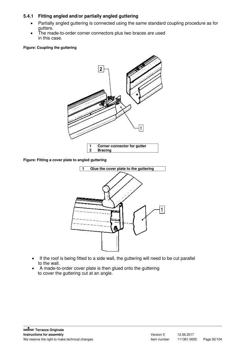
Terrazza Originale
Instructions for assembly Version 5 12.06.2017
We reserve the right to make technical changes Item number 111361-0000 Page 92/104
5.4.1 Fitting angled and/or partially angled guttering
Partially angled guttering is connected using the same standard coupling procedure as for gutters.
The made-to-order corner connectors plus two braces are used in this case.
Figure: Coupling the guttering
1 Corner connector for gutter 2 Bracing
Figure: Fitting a cover plate to angled guttering
1 Glue the cover plate to the guttering
If the roof is being fitted to a side wall, the guttering will need to be cut parallel to the wall.
A made-to-order cover plate is then glued onto the guttering to cover the guttering cut at an angle.

Terrazza Originale
Instructions for assembly Version 5 12.06.2017
We reserve the right to make technical changes Item number 111361-0000 Page 93/104
5.4.2 Installation of posts
On a Terrazza with partially angled guttering, the post is fitted below the straight section of guttering as is standard.
On a Terrazza with partially angled guttering, a notch is cut into the top of the post that is to be fitted below where two sections of guttering join.
Figure: Notched post
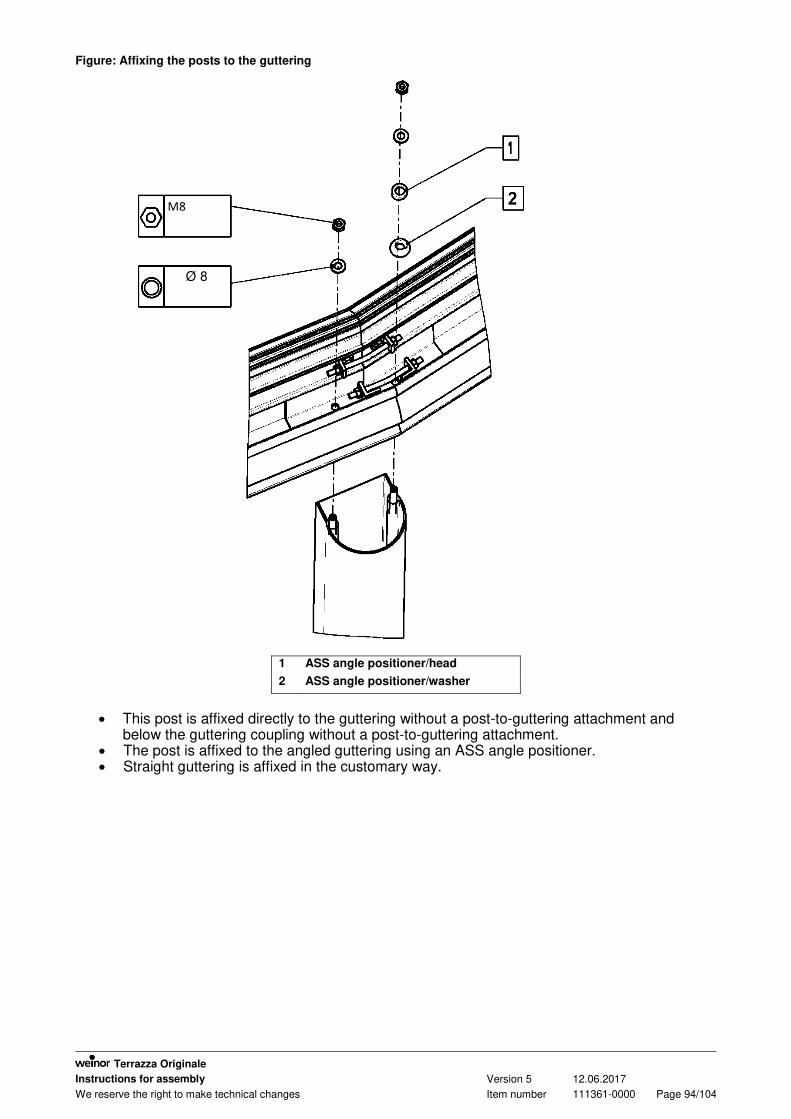
Terrazza Originale
Instructions for assembly Version 5 12.06.2017
We reserve the right to make technical changes Item number 111361-0000 Page 94/104
Figure: Affixing the posts to the guttering
1 ASS angle positioner/head
2 ASS angle positioner/washer
This post is affixed directly to the guttering without a post-to-guttering attachment and
below the guttering coupling without a post-to-guttering attachment. The post is affixed to the angled guttering using an ASS angle positioner. Straight guttering is affixed in the customary way.
Ø 8
M8

Terrazza Originale
Instructions for assembly Version 5 12.06.2017
We reserve the right to make technical changes Item number 111361-0000 Page 95/104
Figure: Guttering pitch
ß Angle of pitch on guttering
On a Terrazza with angled or partially angled guttering, the roof pitch β > 5°, see Figure,
a notch is cut into the top end of the posts and the posts are then fitted without a post-to-guttering attachment.
The post-to-guttering attachment can be used if the guttering pitch is β ≤ 5°. The posts are shortened and unnotched in this case.

Terrazza Originale
Instructions for assembly Version 5 12.06.2017
We reserve the right to make technical changes Item number 111361-0000 Page 96/104
Figure: Angled downspout connection
1 ASS angle positioner/head 2 ASS angle positioner/washer 3 Angled downspout connection
4 Coupling profile for guttering
The angled downspout connection must be fitted to posts that have been designated for
the drain-through-the-post option. A guttering coupling profile must be inserted into the guttering next to each post (except
below the guttering coupling) before the posts are fitted.
M8
Ø 8

Terrazza Originale
Instructions for assembly Version 5 12.06.2017
We reserve the right to make technical changes Item number 111361-0000 Page 97/104
5.4.3 Fitting the roof supports to an angled gutter
The roof supports are fitted to the angled gutter using two 20 mm wide clamping sliders. The side roof supports on the angled guttering must be secured using an additional
clamping slider to prevent them from sliding off to the side, taking both the roof pitch and the angle of the angled guttering into account.
This will require filling the gap between the roof support clamping slider and the cut edge of the guttering with clamping sliders. Trim the clamping sliders to size if necessary.
Leave 2 - 3 mm of play between the inserted clamping slider and the cut edge of the guttering to allow the guttering to compress.
Figure: Affixing the roof support to the guttering
1 Additional clamping slider to prevent guttering from
sliding off to the side 2 Dubo retaining ring M5
3 2-3 mm play to allow guttering to compress
M5

Terrazza Originale
Instructions for assembly Version 5 12.06.2017
We reserve the right to make technical changes Item number 111361-0000 Page 98/104
Figure: Distance between roof support and the joint
When fitting a roof support next to a gutter joint, the distance between the centre of the roof
support to the point where the outer edge of the Terrazza meets the kink in the guttering must be at least 100 mm.
If the angled guttering is pitched at β > 45° or more, the front of the roof supports will need to
be cut at an angle where they meet the guttering so that they do not abut against the guttering. The roof support cover cap can no longer be fitted to the roof supports in this case.
The roof supports are covered using made-to-order plates. The cover plates must be glued onto the roof supports.
Figure: Fitting the roof support cover plate
1 Glue the cover plate to the roof support

Terrazza Originale
Instructions for assembly Version 5 12.06.2017
We reserve the right to make technical changes Item number 111361-0000 Page 99/104
5.4.4 Fitting the stops for the roof covering
Install angle brackets on the roof supports that rest on the angled guttering so that they can
be used as stops for the roof covering. Affix glazing packers between the roof covering and the angle brackets.
Figure: Fitting the shim stop
1 Angle bracket, 20x20x5
2 Clamping slider
Figure: Shim stop
1 Install glazing packers here before inserting the roof covering
M5x10
M5x10
Terrazza Originale
Instructions for assembly Version 5 12.06.2017
We reserve the right to make technical changes Item number 111361-0000 Page 100/104
5.4.5 Sealing, caulking
When erecting the roof and following completion, seal all areas where water could penetrate into the interior. Always ensure you use appropriate sealants. We recommend:
"Takeseal sealant" from Fix-Tec The following areas (among others) must be caulked:
gutter joints Posts that are fitted to the guttering without the post-to-guttering attachment must be
sealed where the join the guttering (especially if these posts have a drain running through them)
along the abutting joint between the two roof support sections on the kinked side roof support
5.4.6 Miscellaneous installation notes
weinor needed the drill holes in the wall bracket in order to construct the roof. The drill holes are not intended to indicate how many mounting holes are actually required on-site or whether the wall bracket can be affixed using the existing drill holes.

Terrazza Originale
Instructions for assembly Version 5 12.06.2017
We reserve the right to make technical changes Item number 111361-0000 Page 101/104
6 Terrazza Originale exploded drawing
Figure: Terrazza Originale exploded drawing

Terrazza Originale
Instructions for assembly Version 5 12.06.2017
We reserve the right to make technical changes Item number 111361-0000 Page 102/104
Item Designation Item (untreated)
Item (painted)
Remarks
1 Guttering cover plate 100429 102177
2 Wall-mounting 110 roof support cover plate 101115 102231
3 Wall-mounting 150 roof support cover plate 100432 102232
4 Wall bracket cover plate 100431 102178
5 Guttering angle bracket cover cap 107850 108051
6 Left-hand guttering cover cap, complete 100389 102176
7 Right-hand guttering cover cap, complete 100389 102176
8 Cap for roof support 110 110329 110331
9 Cap for roof support 150 109435 109872
10 Cover cap for post plate 108017 108127
11 Side roof support cover strip 116214 116240
12 15x20 mm cover profile 114926 115080
13 16 mm cover profile 101061 102223 Optional
14 Post plate cover cap for outside post 117965 117966 Optional
15 Post plate cover cap for centre / wall-mounting post
117967 117968 Optional
16 Left wall-mounting post plate cover cap 108017 108127
17 Right wall-mounting post plate cover cap 108017 108127
18 Aluminium base for post None 102234
19 Post-to-guttering connection 100387 102175
20 180° attachment profile for post 109030 109031
21 Angle bracket for post 101082 None
22 Gutter angle bracket 107851 108052
23 Guttering 101046 102215
24 Universal guttering coupling 109807 None
25 Complete 110 roof support 101039 102208
26 Roof support 150 101038 102207
27 Right wall-mounting 150 roof support None None
28 Downspout seal 101057 None
29 Right 150 side roof support
30 Slide-in profile for post 101172 None
31 53x1.5 mm downspout 111963 112008
32 53x1.5 mm downspout coupling 112007 112008
33 Small base plate for post 116837 116838
34 Glass support with rubber 107895 108220
35 Roof support glazing bead 101040 102209
36 Wall bracket glazing bead 101045 102214
38 Protective leaf grille 113388 None
40 Complete DT110 mounting plate None 101186
41 Complete DT150 mounting plate None 101187
42 90 post 101048 102217
43 Complete outside 115 post None None
44 Complete centre / wall-mounting 115 post None None
45 Post plate for wall 108128 108320
46 Transom 101047 102216
47 Transom cover profile 100067 102144
48 Pipe bend 87° 111870 111871

Terrazza Originale
Instructions for assembly Version 5 12.06.2017
We reserve the right to make technical changes Item number 111361-0000 Page 103/104
49 D53 mm clamp 101123 102233
50 Screw socket, complete None 112061
52 Wall bracket 134 101051 102219
53 Wall bracket 175 101042 102211
54 Top section of wall bracket 34 101054 102222
55 Top section of wall bracket 74 101043 102212
56 Top section of wall bracket 110 101044 102213
57 Side wall bracket 108113 101159
7 Disposal
This product does not contain any materials which pose a risk or danger to other people or the environment. the roof parts should nevertheless be disposed of properly.

Terrazza Originale Instructions for assembly Pent roof type A / Gable roof / Head elements / Special shapes
Terrazza Originale
Instructions for assembly Version 5 12.06.2017
We reserve the right to make technical changes Item number 111361-0000 Page 104/104
weinor GmbH & Co. KG Mathias-Brüggen-Straße 110 50829 Cologne (Germany) www.weinor.com Hotline: +49(0)221/5 97 09-214 Fax: +49(0)221/5 97 09-898