Teri Griha
92
description
Indian Subcontinent Design guidelines by The Energy Resources Institute
Transcript of Teri Griha

National Rating System – GRIHA
(Green Rating for Integrated Habitat Assessment)
An evaluation tool to help design, build, operate, and
maintain a resource-efficient-built environment
Ministry of New and Renewable Energy,
Government of India, New Delhi
and
The Energy and Resources Institute
New Delhi

© Ministry of New and Renewable Energy, Government of India, andThe Energy and Resources Institute, 2008
All rights reserved. No part of this publication may be reproduced in any form or by any means withoutprior written permission of Ministry of New and Renewable Energy, Government of India, and The Energyand Resources Institute.
Published byT E R I PressThe Energy and Resources InstituteDarbari Seth BlockIHC Complex, Lodhi RoadNew Delhi – 110 003India
Printed on recycled paper
Printed in India at New Delhi
Tel. 2468 2100, 4150 4900Fax 2468 2144, 2468 2145
India +91 • Delhi (0) 11E-mail [email protected]
Web www.teriin.org
Contents
Foreword ................................................................................................................... vby Deepak Gupta, Secretary, MNRE, Government of India
Foreword ................................................................................................................... viiby R K Pachauri, Director-General, TERI, New Delhi
PREAMBLE ................................................................................................................................................. 1
1.0 Introducing TERI ..................................................................................................... 1 1.1 Role of TERI in recognizing environment-friendly initiatives .................... 1 1.2 What is a green building? ..................................................................................... 2 1.3 GRIHA: National green building rating system ............................................. 3 1.4 How to get your building rated? ........................................................................ 5 1.5 GRIHA evaluation process ................................................................................... 5 1.6 Synopsis of the criteria for rating ....................................................................... 6 1.7 Scoring points for GRIHA .................................................................................... 9 1.8 Evaluation procedure of criterion of GRIHA .................................................. 10
SECTION 1 SITE SELECTION AND SITE PLANNING ................................................................ 11
Resource conservation and efficient utilization of resources .................................................................. 11Criterion 1 Site selection ............................................................................................................. 11Criterion 2 Preserve and protect landscape during construction .................................... 14Criterion 3 Soil conservation (till post-construction) .......................................................... 18Criterion 4 Design to include existing site features ............................................................ 20Criterion 5 Reduce hard paving on-site and/or provide shaded hard-
paved surfaces ......................................................................................................... 23Criterion 6 Enhance outdoor-lighting system efficiency and use renewable
energy system for meeting outdoor lighting requirement ........................... 26Criterion 7 Plan utilities efficiently and optimize on-site circulation efficiency ......... 27
Health and well-being .................................................................................................................................. 28Criterion 8 Provide minimum level of sanitation/safety facilities for
construction workers .............................................................................................. 28Criterion 9 Reduce air pollution during construction ........................................................ 29
SECTION 2 BUILDING PLANNING AND CONSTRUCTION .................................................... 31Criterion 10 Reduce landscape water requirement ............................................................... 31Criterion 11 Reduce water use in the building ....................................................................... 34Criterion 12 Efficient water use during construction ............................................................ 36Criterion 13 Optimize building design to reduce conventional energy demand .......... 37Criterion 14 Optimize energy performance of building within specified
comfort limits ........................................................................................................... 39Criterion 15 Utilization of fly ash in building structure ...................................................... 42
Criterion 16 Reduce volume, weight, and construction time byadopting efficient technologies (such as pre-cast systems) ......................... 45
Criterion 17 Use low-energy material in interiors ................................................................. 48Criterion 18 Renewable energy utilization .............................................................................. 50Criterion 19 Renewable-energy-based hot water system ..................................................... 52
Recycle, reuse, and recharge of water ........................................................................................................ 54Criterion 20 Waste-water treatment ........................................................................................... 54Criterion 21 Water recycle and reuse (including rainwater) ............................................... 56
Waste management ..................................................................................................................................... 59Criterion 22 Reduction in waste during construction ........................................................... 59Criterion 23 Efficient waste segregation ................................................................................... 60Criterion 24 Storage and disposal of wastes ........................................................................... 61Criterion 25 Resource recovery from waste ............................................................................. 62
Health and well-being .................................................................................................................................. 63Criterion 26 Use low-VOC paints/adhesives/sealants ........................................................ 63Criterion 27 Minimize ozone depleting substances ............................................................... 65Criterion 28 Ensure water quality .............................................................................................. 67Criterion 29 Acceptable outdoor and indoor noise levels ................................................... 69Criterion 30 Tobacco and smoke control .................................................................................. 70Criterion 31 Provide at least, the minimum level of accessibility for persons
with disabilities. ...................................................................................................... 71
SECTION 3 BUILDING OPERATION AND MAINTENANCE ................................................... 73Criterion 32 Energy audit and validation ................................................................................ 73Criterion 33 Operation and maintenance ................................................................................. 74
SECTION 4 INNOVATION POINTS .................................................................................................. 75Criterion 34 Innovation points .................................................................................................... 75
References ........................................................................................................................................... 78
National Rat ing System – ‘GRIHA’ ○ ○ ○ ○ ○ ○ ○ ○ ○ ○ ○ ○ ○ ○ ○ ○ ○ ○ ○ ○ ○ ○ ○ ○ ○ ○ ○ ○ ○ ○ ○ ○
iv Contents ○ ○ ○ ○ ○ ○ ○ ○ ○ ○ ○ ○ ○ ○ ○ ○ ○ ○ ○ ○ ○ ○ ○ ○ ○ ○ ○ ○ ○ ○ ○ ○ ○ ○ ○ ○ ○ ○ ○ ○ ○ ○ ○ ○ ○ ○ ○ ○ ○ ○ ○ ○
Deepak Guptanhid xqIrk SECRETARY
GOVERNMENT OF INDIAMINISTRY OF NEW AND RENEWABLE ENERGY
lfpoHkkjr ljdkj
uohu vkSj uohdj.kh; ÅtkZ ea=ky;
Block No. 14, CGO Complex, Lodi Road, New Delhi – 110 003Tel.: 011-24361481, 24362772 • Fax: 011-24367329 • E-mail: [email protected]

Foreword
The time has come where we can nolonger ignore the benefits of greenbuilding practices that have a major
impact on our environment. The Governmentis taking appropriate steps to ensure thatgreen building practices are mainstreamedthrough a mix of regulations and voluntaryschemes. The National Action Plan on ClimateChange has, therefore, announced a missionon sustainable habitats. In addition, therecently launched ECBC 2007 (EnergyConservation Building Code 2007), the appliancelabelling programme of the Bureau of EnergyEfficiency, and the rating system for appraisaland clearance of large construction projects bythe Ministry of Environment and Forests aresome of the significant steps to move towardsgreen buildings. Several corporateorganizations and institutions have mandatedthe use of green practices in their newconstruction. Development of a holisticframework that meets all the regulatory normsand responds to the needs of differing agro-climatic zones in India is felt to be an urgentneed. GRIHA (Green Rating for IntegratedHabitat Assessment) was developed inresponse to this need.
Keeping in view agro-climatic conditions inIndia and, in particular, the preponderance ofnon-air-conditioned buildings, the NationalRating System – GRIHA – has been developedas a suitable system for all kinds of buildingsin different climatic zones of the country. Thesystem, initially developed by TERI as TERI-GRIHA, has been modified to GRIHA as the
country’s National Rating System afterincorporating various modifications suggestedby a group of architects and experts.
The GRIHA rating system takes intoaccount the provisions of the NationalBuilding Code 2005; the Energy ConservationBuilding Code 2007 announced by BEE andother IS codes.
GRIHA – the National Rating System willevaluate the environmental performance of abuilding holistically over its entire life cycle,thereby providing a definitive standard forwhat constitutes a ‘green building’. The ratingsystem, based on accepted energy andenvironmental principles, will seek to strike abalance between established practices andemerging concepts, both national andinternational.
On a broader scale, this system, along withthe activities and processes that lead up to it,will benefit the community at large withimprovement in the environment by reducingGHG (greenhouse gas) emissions, improvingenergy security, and reducing the stress onnatural resources.
This book provides a comprehensiveunderstanding of GRIHA, its underlyingcriteria and the rating procedure. The bookalso covers best practices that could befollowed to achieve desired GRIHA ratings.
(R K Pachauri)Director-General, TERI


Members of the National Advisory Committee
Secretary, Ministry of New and Renewable Energy Chairman
Director-General, The Energy and Resources Institute Co-Chairman
Senior Representative of the Ministry of Environment and Forests Member(not below Joint Secretary)
Senior Representative of the Ministry of Housing and Urban MemberPoverty Alleviation (not below the rank of Joint Secretary)
Director General, Central Public Works Department Member
Director General, Bureau of Energy Efficiency Member
Additional Director General, Bureau of Indian Standards Member
Principal Secretary, Urban Development, Government Memberof Maharashtra
Municipal Commissioner, Bangalore Member
Director, West Bengal Renewable Energy Development Agency Member
Director, Haryana Renewable Energy Development Agency Member
President, Indian Institute of Architects Member
President, Confederation of Real Estate Developers Associations Memberof India
Advisor, Ministry of New and Renewable Energy Secretary
Head, GRIHA Secretariat, The Energy and Resources Institute Convenor
Members of the Technical Advisory Committee
Advisor, Ministry of New and Renewable Energy Chairman
Shri Sanjay Prakash, Senior Architect, Delhi Member
Dr Vinod Gupta, Senior Architect, Delhi Member
Shri Karan Grover, Senior Architect, Vadodara Member
Shri Ashok B Lal, Senior Architect, Delhi Member
Ms Shakuntala Ghosh, Senior Architect, Kolkata Member
Shri Sanjay Mohe, Senior Architect, Bangalore Member
Chief Architect, Housing and Urban Development Corporation Ltd Member
Shri Tanmay Toathagat, Energy Specialist, Delhi Member
Shri Paritosh Tyagi (ex-Chairman, Central Pollution Control Board) Member
Representative from Bureau of Energy Efficiency Member
Representative from Central Public Works Department Member
Director, Building Materials and Technology Promotion Council Member
Head, GRIHA Secretariat, The Energy and Resources Institute Convenor

1.0 Introducing TERI
TERI (The Energy and ResourcesInstitute), a dynamic and flexibleorganization with a global vision and a
local focus, was established in 1974. Initially thefocus was on documentation and informationdissemination. Research activities in the fieldsof energy, environment, and sustainabledevelopment were initiated towards the end of1982. All these activities were rooted in TERI’sfirm conviction that efficient utilization ofenergy, sustainable use of natural resources,large-scale adoption of renewable energytechnologies, and reduction of all forms of wastewould move the process of developmenttowards the goal of sustainability.
A unique developing-country institution,TERI is deeply committed to every aspect ofsustainable development. From providingenvironment-friendly solutions to rural energyrequirements to helping shape thedevelopment of the Indian oil and gas sector;from tackling global climate change issuesacross continents to helping conserve forests;from advancing solutions to the growingurban transport and air pollution, topromoting energy efficiency in the Indianindustry, the emphasis has always been onfinding innovative solutions to make the worlda better place to live in. Although TERI’svision is global, its roots are firmly entrenchedin the Indian soil. All activities in TERI movefrom formulating local- and national-levelstrategies to shaping global solutions to critical
Preamble
energy and environment-related issues. To thisend, TERI has established regional centres inBangalore, Goa, Guwahati, Kolkata, andMumbai. It has set up affiliate institutes: TERI–NA (The Energy and Resources Institute,North America) in Washington, DC, USA andTERI–Europe, London, UK; and it also has apresence in Japan and Malaysia.
As an extension of its work on environmentmanagement, TERI has designed GRIHA (GreenRating for Integrated Habitat Assessment), a tooldeveloped by TERI for rating the environmentalperformance of buildings, which is now anational rating system.
1.1 Role of TERI in recognizingenvironment-friendly initiatives
1.1.1 TERI Corporate EnvironmentalAwards
The corporate sector is emerging as a criticalplayer in India’s development process. Theenvironmental implications of India’sindustrialization process indicate thatpollution has been rising with, and often fasterthan, the growth in industrial production.Driven by the rising scale and intensity ofenvironmental pressures and the society’schanging expectations from the corporatesector, business and the environment,traditionally seen as divergent issues, aresteadily coming closer.
National Rat ing System – GRIHA ○ ○ ○ ○ ○ ○ ○ ○ ○ ○ ○ ○ ○ ○ ○ ○ ○ ○ ○ ○ ○ ○ ○ ○ ○ ○ ○ ○ ○ ○ ○ ○
2 Preamble ○ ○ ○ ○ ○ ○ ○ ○ ○ ○ ○ ○ ○ ○ ○ ○ ○ ○ ○ ○ ○ ○ ○ ○ ○ ○ ○ ○ ○ ○ ○ ○ ○ ○ ○ ○ ○ ○ ○ ○ ○ ○ ○ ○ ○ ○ ○ ○ ○ ○ ○ ○
Realizing the increasing complexities facingthe environment, corporate houses have begunto recognize their responsibility. In the recentyears, a number of corporate houses havetaken bold and visible steps to integratesustainability elements into their overallcorporate strategy.
In order to provide impetus to sustainabledevelopment and to encourage the ongoingprocess of environmental management andprotection within the corporate sector, TERIinstituted the Corporate EnvironmentalAwards in 2000/01. Encouraged by theoverwhelming response and sincere interestshown by the Indian corporate houses, TERIconfers the awards annually.
1.1.2 TERI Corporate SocialResponsibility Awards
TERI CSR (Corporate Social Responsibility)Awards seeks to identify best practices andinnovations of Indian corporate houses infulfilling their responsibilities towards diversestakeholders. In the process, TERI also aims tosensitize corporate houses to their duties asresponsible citizens of a developing world.
The prime objective of these awards is toassess the extent of integration of CSRconcerns with corporate functioning,responsiveness to the needs of differentstakeholders, and development of innovativepartnership models to fulfil socialresponsibilities.
1.1.3 Eco-rating system – assessing,comparing, and tracking
Eco-rating – an indicator of corporateenvironmental performance/risk at a facilitylevel – has been developed by TERI. Thisrating tool evaluates pollution/environmentalimpact, resource-use efficiency, work-environment contingency, and environmentmanagement systems on an eco-rating model.Based on the evaluation, an indicator of theoverall performance of a unit is provided, arisk profile is assessed, and an assessmentreport is prepared.
1.2 What is a green building?Buildings have major environmental impactsduring their entire life cycle. Resources such as
ground cover, forests, water, and energy aredwindling to give way to buildings. Resource-intensive materials provide structure to abuilding and landscaping adds beauty to it — inturn using up water and pesticides to maintainit. Energy-consuming systems for lighting, airconditioning, and water heating provide comfortto its occupants. Hi-tech controls add intelligenceto ‘inanimate’ buildings so that they can respondto varying conditions, and intelligently monitorand control resource use, security, and usage offire systems and other such systems in thebuilding. Water, another vital resource for theoccupants, gets consumed continuously duringbuilding construction and operation. Severalbuilding processes and occupant functionsgenerate large amounts of waste, which can berecycled for use or can be reused directly.Buildings are thus one of the major pollutantsthat affect urban air quality and contribute toclimate change. Hence the need to design agreen building, the essence of which is toaddress all these issues in an integrated andscientific manner. It is a known fact that it costsmore to design and construct a green building.However, it is also a proven fact that it costs lessto maintain a green building that hastremendous environmental benefits andprovides a better place for the occupants to liveand work in. Thus, the challenge of a greenbuilding is to achieve all its benefits at anaffordable cost.
A green building depletes the naturalresources to a minimum during itsconstruction and operation. The aim of a greenbuilding design is to minimize the demand onnon-renewable resources, maximize theutilization efficiency of these resources whenin use, and maximize the reuse, recycling, andutilization of renewable resources. Itmaximizes the use of efficient buildingmaterials and construction practices; optimizesthe use of on-site sources and sinks by bio-climatic architectural practices; uses minimumenergy to power itself; uses efficientequipment to meet its lighting, air-conditioning, and other needs; maximizes theuse of renewable sources of energy; uses efficientwaste and water management practices; andprovides comfortable and hygienic indoorworking conditions. It is evolved through adesign process that requires input from all
○ ○ ○ ○ ○ ○ ○ ○ ○ ○ ○ ○ ○ ○ ○ ○ ○ ○ ○ ○ ○ ○ ○ ○ ○ ○ ○ ○ ○ ○ ○ ○ National Rat ing System – GRIHA
3○ ○ ○ ○ ○ ○ ○ ○ ○ ○ ○ ○ ○ ○ ○ ○ ○ ○ ○ ○ ○ ○ ○ ○ ○ ○ ○ ○ ○ ○ ○ ○ ○ ○ ○ ○ ○ ○ ○ ○ ○ ○ ○ ○ ○ ○ ○ ○ ○ ○ ○ ○ Preamble
concerned – the architect; landscape designer;and the air conditioning, electrical, plumbing,and energy consultants – to work as a team toaddress all aspects of building and systemplanning, designing, construction, andoperation. They critically evaluate the impactsof each design decision and arrive at viabledesign solutions to minimize the negativeimpacts and enhance the positive impacts onthe environment. In sum, the following aspectsof a green building design are looked into inan integrated way.P Site planningP Building envelope designP Building system design (HVAC [heating
ventilation and air conditioning], lighting,electrical, and water heating)
P Integration of renewable energy sources togenerate energy on-site
P Water and waste managementP Selection of ecologically sustainable
materials (with high recycled content,rapidly renewable resources with lowemission potential, and so on)
P Indoor environmental quality (maintainindoor thermal and visual comfort and airquality)
1.3 GRIHA: National greenbuilding rating system
1.3.1 The context
Internationally, voluntary building ratingsystems have been instrumental in raisingawareness and popularizing green buildingdesigns. However, most of the internationallydevised rating systems have been tailored tosuit the building industry of the country wherethey were developed. TERI, being deeplycommitted to every aspect of sustainabledevelopment, took upon itself theresponsibility of acting as a driving force topopularize green buildings by developing atool for measuring and rating a building’senvironmental performance in the context ofIndia’s varied climate and building practices.This tool, by its qualitative and quantitativeassessment criteria, would be able to ‘rate’ abuilding on the degree of its ‘greenness’. The
rating would be applied to new and existingbuilding stock – commercial, institutional, andresidential – of varied functions.
1.3.2 The challenges
The Indian building industry is highlydecentralized, involving diverse stakeholdersengaged in design, construction, equipmentprovision, installation, and renovation ofbuildings. Each group may be organized to someextent, but there is limited interaction among thegroups, thus disabling the integrated greendesign and application process. Hence, it is veryimportant to define and quantify sustainablebuilding practices and their benefits. It is alsoimperative to delineate the role of each actor inensuring that the building consumes minimalresources in its entire life cycle and leaves behindminimal environmental footprint.
1.3.3 The benefits
TERI’s green building rating will evaluate theenvironmental performance of a buildingholistically over its entire life cycle, therebyproviding a definitive standard for whatconstitutes a ‘green building’. The rating system,based on accepted energy and environmentalprinciples, will seek to strike a balance betweenthe established practices and emerging concepts,both national and international. The guidelines/criteria appraisal may be revised every threeyears to take into account the latest scientificdevelopments during this period.
On a broader scale, this system, along withthe activities and processes that lead up to it,will benefit the community at large with theimprovement in the environment by reducingGHG (greenhouse gas) emissions, improvingenergy security, and reducing the stress onnatural resources.
Some of the benefits of a green design to abuilding owner, user, and the society as awhole are as follows.P Reduced energy consumption without
sacrificing the comfort levelsP Reduced destruction of natural areas,
habitats, and biodiversity, and reduced soilloss from erosion, and other suchdestructive occurrences
P Reduced air and water pollution (withdirect health benefits)
National Rat ing System – GRIHA ○ ○ ○ ○ ○ ○ ○ ○ ○ ○ ○ ○ ○ ○ ○ ○ ○ ○ ○ ○ ○ ○ ○ ○ ○ ○ ○ ○ ○ ○ ○ ○
4 Preamble ○ ○ ○ ○ ○ ○ ○ ○ ○ ○ ○ ○ ○ ○ ○ ○ ○ ○ ○ ○ ○ ○ ○ ○ ○ ○ ○ ○ ○ ○ ○ ○ ○ ○ ○ ○ ○ ○ ○ ○ ○ ○ ○ ○ ○ ○ ○ ○ ○ ○ ○ ○
P Reduced water consumptionP Limited waste generation due to recycling
and reuseP Reduced pollution loadsP Increased user productivityP Enhanced image and marketability
GRIHA’s green design practices, and thearray of individual and institutionalprofessionals who put these in practice, wouldbe publicized and promoted for the followingreasons.P It has immense replication probability for
‘seeing is believing’.P It motivates the user and the owner to fulfil
their commitment to the environment byemulating the example it sets.
P It helps generate awareness on the conceptof green building.
P It stimulates competition among peers toachieve the same performance or toendeavour to better it.
1.3.4 The development andoperationalization process
GRIHA, the national green building ratingsystem, was developed by TERI after athorough study and understanding of thecurrent internationally accepted green buildingrating systems and the prevailing buildingpractices in India. The team has researched onseveral international rating systems. A fewteam members were also sponsored under astudy tour by USAEP (United States AsiaEnvironmental Partnership) to understand theeco-rating systems prevalent in the US. Theteam has vast experience in providing designassistance to green buildings in the countryand long and varied experience in carrying outenergy conservation studies in existing hotels,offices, and other commercial buildings. Theteam has effectively utilized the severalmultidisciplinary strengths and experiences oftheir colleagues at TERI to arrive at the toolsthat addresses crosscutting issues in thedesign, development, and operation of a greenbuilding.
The primary objective of the rating systemis to help design green buildings and, in turn,help evaluate the ‘greenness’ of buildings. Therating system follows best practices along withnational/international codes that are
applicable to the green design of buildings.The green building rating system devised
by TERI is a voluntary scheme. It has deriveduseful inputs from the upcoming mandatorybuilding codes/guidelines being developed bythe BEE (Bureau of Energy Efficiency), theMNRE (Ministry of New and RenewableEnergy), MoEF (Ministry of Environment andForests), and the BIS (Bureau of IndianStandards). The rating system aims to achieveefficient resource utilization and to enhanceresource efficiency and better quality of life inbuildings.
TERI GRIHA has been adopted as a NRS(national rating system) under the MNRE,Government of India, as of 1 November 2007.
1.3.4.1 Operationalization of GRIHA –
the national rating system
National Advisory Council
A NAC (National Advisory Council) has beenconstituted by the MNRE and is convened bythe Advisor of the Ministry. It compriseseminent architects, senior government officialsfrom the Central Ministry, the BEE, the CentralPublic Works Department, and select statenodal agencies; representatives from the ITsector, real estate sector and developers; andrepresentatives from the GRIHA secretariat,TERI. The NAC is chaired by the Secretary,MNRE, and co-chaired by the Director-General, TERI.
The NAC provides advice and direction tothe NRS and is the interface between theMNRE and the rating secretariat, which islocated within TERI. Its broad functions are aslisted below.P Guide the administrative structure for
GRIHAP Decide a fee structureP Endorse the ratingP Recommend incentives and awards by the
Government of India/state governmentsP Endorse modifications/upgrades periodically
Technical Advisory Committee
A TAC (Technical Advisory Committee) hasbeen constituted by the MNRE for providingtechnical advice to the GRIHA team onmodifications and upgradation of the GRIHAframework. The technical advisory team
○ ○ ○ ○ ○ ○ ○ ○ ○ ○ ○ ○ ○ ○ ○ ○ ○ ○ ○ ○ ○ ○ ○ ○ ○ ○ ○ ○ ○ ○ ○ ○ National Rat ing System – GRIHA
5○ ○ ○ ○ ○ ○ ○ ○ ○ ○ ○ ○ ○ ○ ○ ○ ○ ○ ○ ○ ○ ○ ○ ○ ○ ○ ○ ○ ○ ○ ○ ○ ○ ○ ○ ○ ○ ○ ○ ○ ○ ○ ○ ○ ○ ○ ○ ○ ○ ○ ○ ○ Preamble
comprises eminent architects and experts wellversed with design and construction of greenbuildings.
The Ministry proposes to incentivize the NRSwith a view to promote large-scale design andconstruction of green buildings in the country.
1.3.5 The basic features
At present, the system has been developed tohelp ‘design and evaluate’ new buildings(buildings that are still at the inception stages).A building is assessed based on its predictedperformance over its entire life cycle — frominception to operation. The stages of the lifecycle that have been identified for evaluationare pre-construction, building design andconstruction, and building O&M (operationand maintenance). The issues that areaddressed in these stages are as follows.P Pre-construction stage (intra- and inter-site
issues)P Building planning and construction stages
(issues of resource conservation andreduction in resource demand, resourceutilization efficiency, resource recovery andreuse, and provisions for occupant healthand well-being). The prime resources thatare considered in this section are land,water, energy, air, and green cover.
P Building O&M stage (issues of O&M ofbuilding systems and processes, monitoringand recording of consumption, and occupanthealth and well-being, and also issues thataffect the global and local environment).
1.4 How to get your buildingrated?All buildings, except for industrial complexesand housing colonies, which are in the designstage, are eligible for certification under the TERIGRIHA system. Buildings include offices, retailspaces, institutional buildings, hotels, hospitalbuildings, health care facilities, residences, andmulti-family high-rise buildings.
1.4.1 Registration
P A project has to be registered with TERI byfilling in an online registration formavailable on the TERI website.
P Registration cost details are available on theWeb. Registration should preferably be
done at beginning of a project, as there areseveral issues that need to be addressed atthe pre-design stage.
P The registration process includes access tothe essential information related to rating,application form, list of submissions, scorepoints, and the weightage system. Ifdesired by an applicant, a one-day training(for the design team) on the rating systemis also included at a nominal additionalcost.
During the training session, the followingareas will be covered.P Overview of the green building designP Building project and project-specific
guidance systemP Documentation processP Evaluation process
1.4.2 Documentation
The evaluation system covers interdisciplinaryareas. Submissions required for meeting anyparticular criterion are elaborated in specificsections.
1.4.3 Schedule for receipt ofdocuments
All documents (in soft version) related to theattempted criteria should be submitted alongwith the application (pre-construction stage).Only the attempted criteria will be reviewedand a checklist of the same will be attached.
The document covers the details required forapplying for certification. Queries on the rating,which will be responded to within two workingdays, should be sent to [email protected].
1.5 GRIHA evaluation processThe buildings will be evaluated and rated in athree-tier process. The preliminary evaluationwill be done by a team of professionals andexperts from TERI. The TERI team will evaluatethe project and award points. Documents shouldbe submitted in the format prescribed by GRIHAand should be complete in all respects for allattempted criteria. Any attempted criteria forwhich the documentation is incomplete will notbe evaluated. The documentation formats areprovided in a CD along with the GRIHAdocuments.
National Rat ing System – GRIHA ○ ○ ○ ○ ○ ○ ○ ○ ○ ○ ○ ○ ○ ○ ○ ○ ○ ○ ○ ○ ○ ○ ○ ○ ○ ○ ○ ○ ○ ○ ○ ○
6 Preamble ○ ○ ○ ○ ○ ○ ○ ○ ○ ○ ○ ○ ○ ○ ○ ○ ○ ○ ○ ○ ○ ○ ○ ○ ○ ○ ○ ○ ○ ○ ○ ○ ○ ○ ○ ○ ○ ○ ○ ○ ○ ○ ○ ○ ○ ○ ○ ○ ○ ○ ○ ○
The team will first review the mandatorycriteria and reject a project in the event of non-compliance with such criteria. It will thenevaluate the optional criteria and estimate thetotal number of achievable points. Allcompliance of documents will be checked andvetted through the appraisal process as outlinedby GRIHA.
The evaluation summary report will be sentto members of the GRIHA evaluationcommittee comprising of renowned sectorexperts from landscape architecture, lightingand HVAC design, renewable energy, waterand waste management, and buildingmaterials. The committee members will vet thepoints estimated by the technical team andindependently review the documents for theaward of points. The committee will use theevaluation summary report submitted by thetechnical team as a guiding document and willaward provisional points and also comment onspecific criteria, if need be. The evaluationreport will be sent to the project proponent toreview the same and, if desired, take steps toincrease the score. The report will elaborate onthe results of the evaluation committee alongwith its comments. The report will also list thecriteria for which the documentation isincomplete, detailing all the requiredinformation. The client will then be given onemonth to resubmit the document withnecessary modifications. The resubmittedreport should comprise only of additionaldocuments/information desired in theevaluation report, which will again be putthrough the vetting process as describedabove. The evaluation committee will thenaward the final score, which will be presentedto an advisory committee comprising ofeminent personalities and renownedprofessionals in the field for approval andaward of rating. The rating will be valid for aperiod of five years from the date ofcommissioning of the building. TERI reservesthe right to undertake a random audit of anycriteria for which points have been awarded.
1.6 Synopsis of the criteria forratingThe criteria have been categorized as follows.
1.6.1 Site planning
Conservation and efficient utilization
of resources
Objective
To maximize the conservation and utilizationof resources (land, water, natural habitat, avifauna, and energy) and enhance efficiency ofthe systems and operations.
Criterion 1 Site selection
Criterion 2 Preserve and protect the landscapeduring construction/compensatory depositoryforestation
CommitmentProper timing of the construction, preservetopsoil and existing vegetation, staging andspill prevention, and erosion andsedimentation control. Replant on-site treesin the ratio 1:3 to those removed duringconstruction.
Criterion 3 Soil conservation (till post-construction)
CommitmentProper topsoil laying, stabilization of thesoil, and maintenance of adequate fertilityof the soil to support vegetative growth.
Criterion 4 Design to include existing sitefeatures
CommitmentMinimize the disruption of the naturalecosystem and design to harness maximumbenefits of the prevailing micro-climate.
Criterion 5 Reduce hard paving on-site and/or provide shaded hard-paved surfaces
CommitmentMinimize storm water run-off by reducinghard paving on-site.
Criterion 6 Enhance outdoor lighting systemefficiency
CommitmentMeet minimum allowable luminousefficacy (as per lamp type) and makeprogressive use of a renewable-energy-based lighting system.
Criterion 7 Plan utilities efficiently andoptimize on-site circulation efficiency
CommitmentMinimize road and pedestrian walkway
○ ○ ○ ○ ○ ○ ○ ○ ○ ○ ○ ○ ○ ○ ○ ○ ○ ○ ○ ○ ○ ○ ○ ○ ○ ○ ○ ○ ○ ○ ○ ○ National Rat ing System – GRIHA
7○ ○ ○ ○ ○ ○ ○ ○ ○ ○ ○ ○ ○ ○ ○ ○ ○ ○ ○ ○ ○ ○ ○ ○ ○ ○ ○ ○ ○ ○ ○ ○ ○ ○ ○ ○ ○ ○ ○ ○ ○ ○ ○ ○ ○ ○ ○ ○ ○ ○ ○ ○ Preamble
length by appropriate planning andprovide aggregate corridors for utility lines.
Health and well-being
Objectives
To protect the health of construction workersand prevent pollution.
Criterion 8 Provide at least the minimumlevel of sanitation/safety facilities forconstruction workers
CommitmentEnsure cleanliness of workplace withregard to the disposal of waste and effluent,provide clean drinking water and latrinesand urinals as per applicable standard.
Criterion 9 Reduce air pollution duringconstruction
CommitmentEnsure proper screening, coveringstockpiles, covering brick and loads ofdusty materials, wheel-washing facility,and water spraying facility.
1.6.2 Building planning andconstruction stage
Conservation and efficient utilization of
resources
Objective
To maximize resource (water, energy, andmaterials) conservation and enhance efficiencyof the system and operations.
Water
Criterion 10 Reduce landscape waterrequirement
CommitmentLandscape using native species and reducelawn areas while enhancing the irrigationefficiency and reducing the waterrequirement for landscaping purposes.
Criterion 11 Reduce building water useCommitmentReduce building water use by applyinglow-flow fixtures and other similar tools.
Criterion 12 Efficient water use duringconstruction
CommitmentUse materials such as pre-mixed concrete
for preventing loss during mixing. Userecycled treated water and control thewaste of curing water.
Energy: end use
Criterion 13 Optimize building design toreduce the conventional energy demand
CommitmentPlan appropriately to reflect climateresponsiveness, adopt an adequate comfortrange, less air-conditioned areas,daylighting, avoid over-design of thelighting and air-conditioning systems.
Criterion 14 Optimize the energyperformance of the building within specifiedcomfort limits
CommitmentEnsure that energy consumptionin building under a specified category is10%–40% less than that benchmarkedthrough a simulation exercise.
Energy: embodied andconstruction
Criterion 15 Utilization of fly ash in thebuilding structure
CommitmentUse of fly ash for RCC (reinforced cementconcrete) structures with in-fill walls andload bearing structures, mortar, andbinders.
Criterion 16 Reduce volume, weight, and timeof construction by adopting an efficienttechnology (such as pre-cast systems, ready-mix concrete, and others)
CommitmentReplace a part of the energy-intensivematerials with less energy-intensivematerials and/or utilize regionallyavailable materials, which use low-energy/energy-efficient technologies.
Criterion 17 Use low-energy material in theinteriors
CommitmentMinimum 70% in each of the threecategories of interiors (internal partitions,panelling/false ceiling/interior woodfinishes/in-built furniture door/window
National Rat ing System – GRIHA ○ ○ ○ ○ ○ ○ ○ ○ ○ ○ ○ ○ ○ ○ ○ ○ ○ ○ ○ ○ ○ ○ ○ ○ ○ ○ ○ ○ ○ ○ ○ ○
8 Preamble ○ ○ ○ ○ ○ ○ ○ ○ ○ ○ ○ ○ ○ ○ ○ ○ ○ ○ ○ ○ ○ ○ ○ ○ ○ ○ ○ ○ ○ ○ ○ ○ ○ ○ ○ ○ ○ ○ ○ ○ ○ ○ ○ ○ ○ ○ ○ ○ ○ ○ ○ ○
frames, flooring) from low-energymaterials/finishes to minimize the usage ofwood.
Energy: renewable
Criterion 18 Renewable energy utilizationCommitmentMeet energy requirements for a minimumof 10% of the internal lighting load (forgeneral lighting) or its equivalent fromrenewable energy sources (solar, wind,biomass, fuel cells, and others). Energyrequirements will be calculated based onrealistic assumptions which will be subjectto verification during appraisal.
Criterion 19 Renewable-energy-based hot-water system
CommitmentMeet 70% or more of the annual energyrequired for heating water through renewableenergy based water-heating systems.
Recycle, recharge, and reuse ofwater
Objective
To promote the recycle and reuse of water.
Criterion 20 Waste-water treatmentCommitmentProvide necessary treatment of water forachieving the desired concentration ofeffluents.
Criterion 21 Water recycle and reuse(including rainwater)
CommitmentProvide waste-water treatment on-site forachieving prescribed concentration,rainwater harvesting, reuse of treated wastewater and rainwater for meeting thebuilding’s water and irrigation demand.
Waste management
Objective
To minimize waste generation; streamlinewaste segregation, storage, and disposal; andpromote resource recovery from waste.
Criterion 22 Reduction in waste duringconstruction
CommitmentEnsure maximum resource recovery andsafe disposal of wastes generated duringconstruction and reduce the burden onlandfill.
Criterion 23 Efficient waste segregationCommitmentUse different coloured bins for collectingdifferent categories of waste from thebuilding.
Criterion 24 Storage and disposal of wasteCommitmentAllocate separate space for the collectedwaste before transferring it to therecycling/disposal stations.
Criterion 25 Resource recovery from wasteCommitmentEmploy resource recovery systems forbiodegradable waste as per the Solid WasteManagement and Handling Rules, 2000 of theMoEF. Make arrangements for recycling ofwaste through local dealers.
Health and well-being
Objective
To ensure healthy indoor air quality, waterquality, and noise levels, and to reduce theglobal warming potential.
Criterion 26 Use of low VOC (volatile organiccompounds) paints/adhesives/sealants
CommitmentUse only low VOC paints in the interior ofthe building. Use water–based rather thansolvent-based sealants and adhesives.
Criterion 27 Minimize ozone-depletingsubstances
CommitmentEmploy 100% zero ODP (ozone depletionpotential) insulation, HCFC (hydrochloro-fluorocarbon)/and CFC (chlorofluoro-carbon), free HVAC, and refrigerationequipments/and halon-free firesuppression and fire extinguishing systems.
Criterion 28 Ensure water qualityCommitmentEnsure groundwater and municipal water
○ ○ ○ ○ ○ ○ ○ ○ ○ ○ ○ ○ ○ ○ ○ ○ ○ ○ ○ ○ ○ ○ ○ ○ ○ ○ ○ ○ ○ ○ ○ ○ National Rat ing System – GRIHA
9○ ○ ○ ○ ○ ○ ○ ○ ○ ○ ○ ○ ○ ○ ○ ○ ○ ○ ○ ○ ○ ○ ○ ○ ○ ○ ○ ○ ○ ○ ○ ○ ○ ○ ○ ○ ○ ○ ○ ○ ○ ○ ○ ○ ○ ○ ○ ○ ○ ○ ○ ○ Preamble
meet the water quality norms as prescribedin the Indian Standards for variousapplications (Indian Standards for drinking[IS 10500-1991], irrigation applications [IS11624-1986]). In case the water qualitycannot be ensured, provide necessarytreatment of raw water for achieving thedesired concentration for variousapplications.
Criterion 29 Acceptable outdoor and indoornoise levels
CommitmentEnsure outdoor noise level conforms to theCPCB (Central Pollution Control Board)–Environmental Standards–Noise (ambientstandards) and indoor noise levelconforms to the NBC (National BuildingCode of India) 2005 (BIS 2005a).
Criterion 30 Tobacco and smoke controlCommitmentZero exposure to tobacco smoke for non-smokers, and exclusive ventilation forsmoking rooms.
Criterion 31 Provide the minimum level ofaccessibility for persons with disabilities.
CommitmentTo ensure accessibility and usability of thebuilding and its facilities by employees,visitors, and clients with disabilities
Criterion 32 Energy audit and validationCommitmentEnergy audit report to be prepared byapproved auditors of the BEE, Governmentof India.
Criterion 33 Building operation andmaintenance
CommitmentValidate and maintain ‘green’ performancelevels/adopt and propagate green practicesand concepts.
Ensure the inclusion of a specific clause inthe contract document for the commissioningof all electrical and mechanical systems to bemaintained by the owner, supplier oroperator. Provide a core facility/servicemanagement group, if applicable, which willbe responsible for the O&M of the buildingand the electrical and mechanical systemsafter commissioning. Owner/builder/
occupants/service or facility managementgroup to prepare a fully documentedoperations and maintenance manual, CD,multimedia or an information brochurelisting the best practices/dos and don’ts/maintenance requirements for the buildingand the electrical and mechanical systemsalong with the names and addresses of themanufacturers/suppliers of the respectivesystem.
Criterion 34 Innovation pointsCommitmentFour innovation points are available underthe rating system for adopting criteriawhich enhances the green intent of aproject, and one can apply for theinnovation points Some of the probablepoints areP alternative transportationP environmental educationP company policy on green supply chainP enhanced accessibility for physically/
mentally challengedP life cycle cost analysisP any other criteria proposed by applicant
Please note that these innovation pointsare beyond the 100 point and a project canapply for 104 points in all, while the scoringshall be given on a 100-point scale only.
1.7 Scoring points for GRIHAGRIHA is a guiding and performance-orientedsystem where points are earned for meetingthe design and performance intent of thecriteria. Each criterion has points assigned toit. It means that a project intending to meet thecriterion would qualify for the points.Compliances, as specified in the relevantcriterion, have to be submitted in theprescribed format. While the intent of some ofthe criteria is self-validating in nature, thereare others (for example energy consumption,thermal and visual comfort, noise controlcriteria, and indoor pollution levels) whichneed to be validated on-site throughperformance monitoring. The points related tothese criteria (specified under the relevantsections) are awarded provisionally whilecertifying and are converted to firm points
National Rat ing System – GRIHA ○ ○ ○ ○ ○ ○ ○ ○ ○ ○ ○ ○ ○ ○ ○ ○ ○ ○ ○ ○ ○ ○ ○ ○ ○ ○ ○ ○ ○ ○ ○ ○
10 Preamble ○ ○ ○ ○ ○ ○ ○ ○ ○ ○ ○ ○ ○ ○ ○ ○ ○ ○ ○ ○ ○ ○ ○ ○ ○ ○ ○ ○ ○ ○ ○ ○ ○ ○ ○ ○ ○ ○ ○ ○ ○ ○ ○ ○ ○ ○ ○ ○ ○ ○ ○ ○
through monitoring, validation, anddocuments/photographs to support the awardof point.
GRIHA has a 100-point system consistingof some core points, which are mandatory tobe met while the rest are optional points,which can be earned by complying with thecommitment of the criterion for which thepoint is allocated. Different levels ofcertification (one star to five stars) areawarded based on the number of pointsearned. The minimum points required forcertification is 50. Buildings scoring 50–60points, 61–70 points, 71–80 points, and 81–90points will get one star, two stars, three stars,and four stars, respectively. A building scoring91–100 points will receive the maximumrating, which is five stars.
Points scored Rating
50–60 One star61–70 Two stars71–80 Three stars81–90 Four stars91–100 Five stars
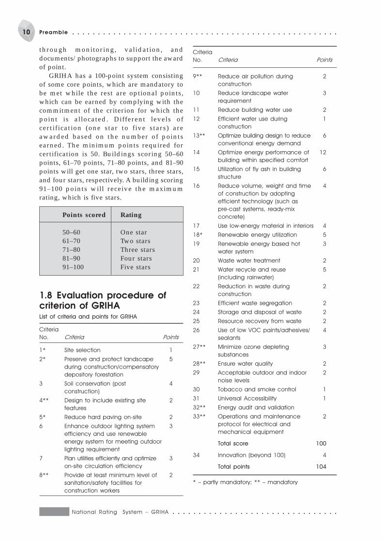
1.8 Evaluation procedure ofcriterion of GRIHAList of criteria and points for GRIHA
Criteria
No. Criteria Points
1* Site selection 1
2* Preserve and protect landscape 5
during construction/compensatory
depository forestation
3 Soil conservation (post 4
construction)
4** Design to include existing site 2
features
5* Reduce hard paving on-site 2
6 Enhance outdoor lighting system 3
efficiency and use renewable
energy system for meeting outdoor
lighting requirement
7 Plan utilities efficiently and optimize 3
on-site circulation efficiency
8** Provide at least minimum level of 2
sanitation/safety facilities for
construction workers
9** Reduce air pollution during 2
construction
10 Reduce landscape water 3
requirement
11 Reduce building water use 2
12 Efficient water use during 1
construction
13** Optimize building design to reduce 6
conventional energy demand
14 Optimize energy performance of 12
building within specified comfort
15 Utilization of fly ash in building 6
structure
16 Reduce volume, weight and time 4
of construction by adopting
efficient technology (such as
pre-cast systems, ready-mix
concrete)
17 Use low-energy material in interiors 4
18* Renewable energy utilization 5
19 Renewable energy based hot 3
water system
20 Waste water treatment 2
21 Water recycle and reuse 5
(including rainwater)
22 Reduction in waste during 2
construction
23 Efficient waste segregation 2
24 Storage and disposal of waste 2
25 Resource recovery from waste 2
26 Use of low VOC paints/adhesives/ 4
sealants
27** Minimize ozone depleting 3
substances
28** Ensure water quality 2
29 Acceptable outdoor and indoor 2
noise levels
30 Tobacco and smoke control 1
31 Universal Accessibility 1
32** Energy audit and validation
33** Operations and maintenance 2
protocol for electrical and
mechanical equipment
Total score 100
34 Innovation (beyond 100) 4
Total points 104
* – partly mandatory; ** – mandatory
Criteria
No. Criteria Points
Resource conservation and efficient utilization of resources
Criterion 1 P Site selection
Objective
Site selection is the first step to a sustainable habitat and needs to be done appropriately, prior
to commencement of design phase. Site selection and analysis should be carried out to create
living spaces that are in harmony with the local environment. The development of a project
should not cause damage to the natural surroundings of the site but, in fact, should try to
improve it by restoring its balance. Thus, site selection should be carried out in light of a holistic
perspective of land use, development intensity, social well-being, and preservation of the
environment.
S E C T I O N 1Site selection and
site planning
given site is of prime importance. The criteriafor getting points under this head have beenelaborated below. The resource efficiencymeasures are aimed at applying appropriatesite planning techniques, concepts and designinterventions in order to enhance the efficientutilization of site resources, minimize on-sitevehicular pollution, enhance energy efficiencyof site lighting, and enhance functionalefficiency of the utility lines.
The process of site selection forsustainable development involvesidentifying and analysing the site with
respect to the sustainable building designcriteria. The development of the site forbuilding purposes requires disruption anddisturbance of the existing natural system. Themost sustainable and environment-sensitivedevelopment is one that entails minimal sitedisturbance. Thus, resource conservation in a
1.1 Commitment1.1.1 The selected site should be in conformitywith the development plan/master plan/UDPFI (Urban Development PlansFormulation and Implementation) guidelines(mandatory). This should comply with theprovisions of eco-sensitive zone regulations,coastal zone regulations, heritage areas
(identified in the master plan or issuedseparately as specific guidelines), water bodyzones (in such zones, no construction ispermitted in the water-spread and buffer beltof 30 m minimum around the FTL [full tanklevel]), various hazard prone area regulations,and others if the site falls under any such area.
National Rat ing System – GRIHA ○ ○ ○ ○ ○ ○ ○ ○ ○ ○ ○ ○ ○ ○ ○ ○ ○ ○ ○ ○ ○ ○ ○ ○ ○ ○ ○ ○ ○ ○ ○ ○
12 Section 1 Si te select ion and s i te planning ○ ○ ○ ○ ○ ○ ○ ○ ○ ○ ○ ○ ○ ○ ○ ○ ○ ○ ○ ○ ○ ○ ○ ○ ○ ○ ○ ○ ○ ○ ○ ○
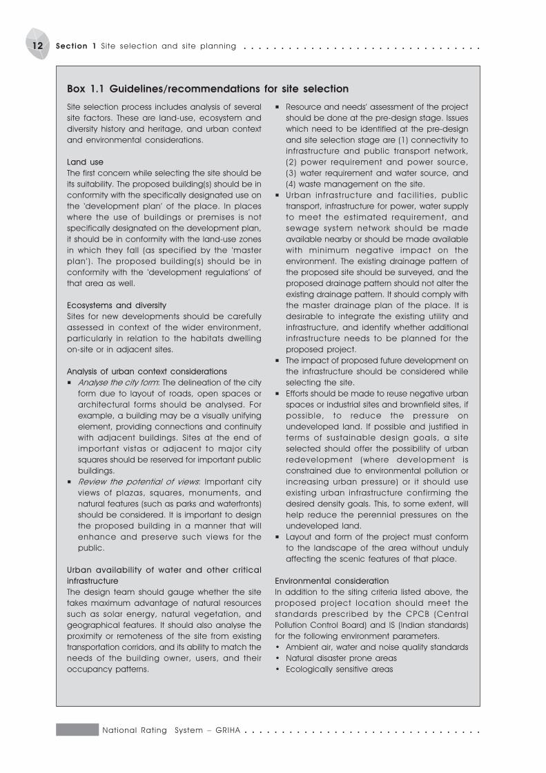
Box 1.1 Guidelines/recommendations for site selection
Site selection process includes analysis of several
site factors. These are land-use, ecosystem and
diversity history and heritage, and urban context
and environmental considerations.
Land use
The first concern while selecting the site should be
its suitability. The proposed building(s) should be in
conformity with the specifically designated use on
the ‘development plan’ of the place. In places
where the use of buildings or premises is not
specifically designated on the development plan,
it should be in conformity with the land-use zones
in which they fall (as specified by the ‘master
plan’). The proposed building(s) should be in
conformity with the ‘development regulations’ of
that area as well.
Ecosystems and diversity
Sites for new developments should be carefully
assessed in context of the wider environment,
particularly in relation to the habitats dwelling
on-site or in adjacent sites.
Analysis of urban context considerations
P Analyse the city form: The delineation of the city
form due to layout of roads, open spaces or
architectural forms should be analysed. For
example, a building may be a visually unifying
element, providing connections and continuity
with adjacent buildings. Sites at the end of
important vistas or adjacent to major city
squares should be reserved for important public
buildings.
P Review the potential of views: Important city
views of plazas, squares, monuments, and
natural features (such as parks and waterfronts)
should be considered. It is important to design
the proposed building in a manner that will
enhance and preserve such views for the
public.
Urban availabil ity of water and other crit ical
infrastructure
The design team should gauge whether the site
takes maximum advantage of natural resources
such as solar energy, natural vegetation, and
geographical features. It should also analyse the
proximity or remoteness of the site from existing
transportation corridors, and its ability to match the
needs of the building owner, users, and their
occupancy patterns.
P Resource and needs’ assessment of the project
should be done at the pre-design stage. Issues
which need to be identified at the pre-design
and site selection stage are (1) connectivity to
infrastructure and public transport network,
(2) power requirement and power source,
(3) water requirement and water source, and
(4) waste management on the site.
P Urban infrastructure and faci l i t ies, publ ic
transport, infrastructure for power, water supply
to meet the est imated requirement, and
sewage system network should be made
available nearby or should be made available
with minimum negative impact on the
environment. The existing drainage pattern of
the proposed site should be surveyed, and the
proposed drainage pattern should not alter the
existing drainage pattern. It should comply with
the master drainage plan of the place. It is
desirable to integrate the existing utility and
infrastructure, and identify whether additional
infrastructure needs to be planned for the
proposed project.
P The impact of proposed future development on
the infrastructure should be considered while
selecting the site.
P Efforts should be made to reuse negative urban
spaces or industrial sites and brownfield sites, if
possible, to reduce the pressure on
undeveloped land. If possible and justified in
terms of sustainable design goals, a s i te
selected should offer the possibility of urban
redevelopment (where development is
constrained due to environmental pollution or
increasing urban pressure) or it should use
existing urban infrastructure confirming the
desired density goals. This, to some extent, will
help reduce the perennial pressures on the
undeveloped land.
P Layout and form of the project must conform
to the landscape of the area without unduly
affecting the scenic features of that place.
Environmental consideration
In addition to the siting criteria listed above, the
proposed project location should meet the
standards prescr ibed by the CPCB (Central
Pollution Control Board) and IS (Indian standards)
for the following environment parameters.
· Ambient air, water and noise quality standards
· Natural disaster prone areas
· Ecologically sensitive areas
○ ○ ○ ○ ○ ○ ○ ○ ○ ○ ○ ○ ○ ○ ○ ○ ○ ○ ○ ○ ○ ○ ○ ○ ○ ○ ○ ○ ○ ○ ○ ○ National Rat ing System – GRIHA
13○ ○ ○ ○ ○ ○ ○ ○ ○ ○ ○ ○ ○ ○ ○ ○ ○ ○ ○ ○ ○ ○ ○ ○ ○ ○ ○ ○ ○ ○ ○ ○ Section 1: S i te select ion and s i te planning
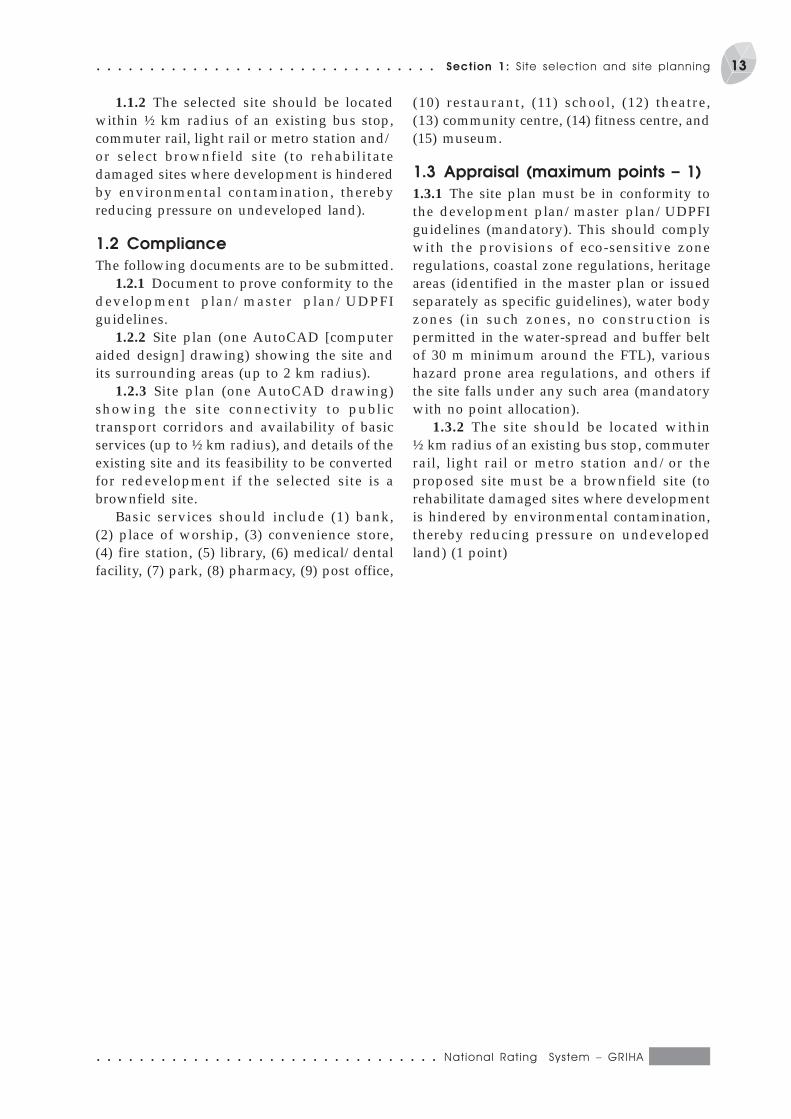
1.1.2 The selected site should be locatedwithin ½ km radius of an existing bus stop,commuter rail, light rail or metro station and/or select brownfield site (to rehabilitatedamaged sites where development is hinderedby environmental contamination, therebyreducing pressure on undeveloped land).
1.2 Compliance
The following documents are to be submitted.1.2.1 Document to prove conformity to the
development plan/master plan/UDPFIguidelines.
1.2.2 Site plan (one AutoCAD [computeraided design] drawing) showing the site andits surrounding areas (up to 2 km radius).
1.2.3 Site plan (one AutoCAD drawing)showing the site connectivity to publictransport corridors and availability of basicservices (up to ½ km radius), and details of theexisting site and its feasibility to be convertedfor redevelopment if the selected site is abrownfield site.
Basic services should include (1) bank,(2) place of worship, (3) convenience store,(4) fire station, (5) library, (6) medical/dentalfacility, (7) park, (8) pharmacy, (9) post office,
(10) restaurant, (11) school, (12) theatre,(13) community centre, (14) fitness centre, and(15) museum.
1.3 Appraisal (maximum points – 1)
1.3.1 The site plan must be in conformity tothe development plan/master plan/UDPFIguidelines (mandatory). This should complywith the provisions of eco-sensitive zoneregulations, coastal zone regulations, heritageareas (identified in the master plan or issuedseparately as specific guidelines), water bodyzones (in such zones, no construction ispermitted in the water-spread and buffer beltof 30 m minimum around the FTL), varioushazard prone area regulations, and others ifthe site falls under any such area (mandatorywith no point allocation).
1.3.2 The site should be located within½ km radius of an existing bus stop, commuterrail, light rail or metro station and/or theproposed site must be a brownfield site (torehabilitate damaged sites where developmentis hindered by environmental contamination,thereby reducing pressure on undevelopedland) (1 point)
National Rat ing System – GRIHA ○ ○ ○ ○ ○ ○ ○ ○ ○ ○ ○ ○ ○ ○ ○ ○ ○ ○ ○ ○ ○ ○ ○ ○ ○ ○ ○ ○ ○ ○ ○ ○
14 Section 1 Si te select ion and s i te planning ○ ○ ○ ○ ○ ○ ○ ○ ○ ○ ○ ○ ○ ○ ○ ○ ○ ○ ○ ○ ○ ○ ○ ○ ○ ○ ○ ○ ○ ○ ○ ○
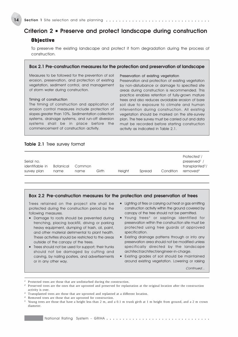
Box 2.1 Pre-construction measures for the protection and preservation of landscape
Table 2.1 Tree survey format
Protected1 /
Serial no. preserved2 /
identifiable in Botanical Common transplanted3 /
survey plan name name Girth Height Spread Condition removed4
Box 2.2 Pre-construction measures for the protection and preservation of trees
1 Protected trees are those that are undisturbed during the construction.2 Preserved trees are the ones that are uprooted and preserved for replantation at the original location after the construction
activity is over.3 Transplanted trees are those that are uprooted and replanted at a different location.4 Removed trees are those that are uprooted for construction.5 Young trees are those that have a height less than 2 m, and a 0.1 m trunk girth at 1 m height from ground, and a 2 m crown
diameter.
P Lighting of fires or carrying out heat or gas emitting
construction activity within the ground covered by
canopy of the tree should not be permitted.
P Young trees5 or sapl ings ident i f ied for
preservation within the construction site must be
protected using tree guards of approved
specification.
P Existing drainage patterns through or into any
preservation area should not be modified unless
specif ical ly di rected by the landscape
architect/architect/engineer-in-charge.
P Existing grades of soil should be maintained
around existing vegetation. Lowering or raising
Continued...
Criterion 2 P Preserve and protect landscape during construction
Objective
To preserve the existing landscape and protect it from degradation during the process of
construction.
Measures to be followed for the prevention of soil
erosion, preservation, and protection of existing
vegetation, sediment control, and management
of storm water during construction.
Timing of construction
The timing of construction and application of
erosion control measures include protection of
slopes greater than 10%. Sedimentation collection
systems, drainage systems, and run-off diversion
systems shal l be in place before the
commencement of construction activity.
Preservation of existing vegetation
Preservation and protection of existing vegetation
by non-disturbance or damage to specified site
areas during construction is recommended. This
practice enables retention of fully-grown mature
trees and also reduces avoidable erosion of bare
soi l due to exposure to cl imate and human
intervent ion dur ing construct ion. Al l exist ing
vegetation should be marked on the site-survey
plan. The tree survey must be carried out and data
must be recorded before starting construction
activity as indicated in Table 2.1.
Trees retained on the project s i te shal l be
protected during the construction period by the
following measures.
P Damage to roots should be prevented during
trenching, placing backfill, driving or parking
heavy equipment, dumping of trash, oil, paint,
and other material detrimental to plant health.
These activities should be restricted to the areas
outside of the canopy of the trees.
P Trees should not be used for support; their trunks
should not be damaged by cutt ing and
carving, by nailing posters, and advertisements
or in any other way.
○ ○ ○ ○ ○ ○ ○ ○ ○ ○ ○ ○ ○ ○ ○ ○ ○ ○ ○ ○ ○ ○ ○ ○ ○ ○ ○ ○ ○ ○ ○ ○ National Rat ing System – GRIHA
15○ ○ ○ ○ ○ ○ ○ ○ ○ ○ ○ ○ ○ ○ ○ ○ ○ ○ ○ ○ ○ ○ ○ ○ ○ ○ ○ ○ ○ ○ ○ ○ Section 1: S i te select ion and s i te planning
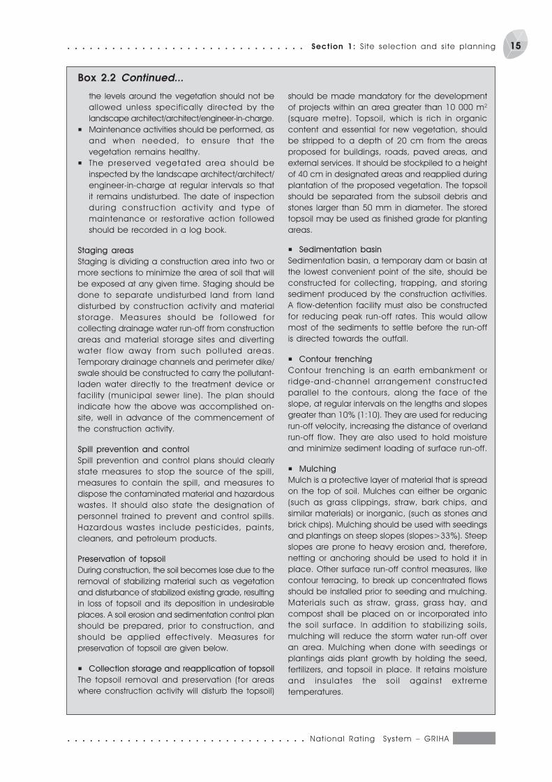
the levels around the vegetation should not be
allowed unless specifically directed by the
landscape architect/architect/engineer-in-charge.
P Maintenance activities should be performed, as
and when needed, to ensure that the
vegetation remains healthy.
P The preserved vegetated area should be
inspected by the landscape architect/architect/
engineer-in-charge at regular intervals so that
it remains undisturbed. The date of inspection
dur ing construct ion activ i ty and type of
maintenance or restorative action followed
should be recorded in a log book.
Staging areas
Staging is dividing a construction area into two or
more sections to minimize the area of soil that will
be exposed at any given time. Staging should be
done to separate undisturbed land from land
disturbed by construction activity and material
storage. Measures should be fol lowed for
collecting drainage water run-off from construction
areas and material storage sites and diverting
water f low away f rom such pol luted areas.
Temporary drainage channels and perimeter dike/
swale should be constructed to carry the pollutant-
laden water directly to the treatment device or
facility (municipal sewer line). The plan should
indicate how the above was accomplished on-
site, well in advance of the commencement of
the construction activity.
Spill prevention and control
Spill prevention and control plans should clearly
state measures to stop the source of the spill,
measures to contain the spill, and measures to
dispose the contaminated material and hazardous
wastes. It should also state the designation of
personnel trained to prevent and control spills.
Hazardous wastes include pesticides, paints,
cleaners, and petroleum products.
Preservation of topsoil
During construction, the soil becomes lose due to the
removal of stabilizing material such as vegetation
and disturbance of stabilized existing grade, resulting
in loss of topsoil and its deposition in undesirable
places. A soil erosion and sedimentation control plan
should be prepared, prior to construction, and
should be applied effectively. Measures for
preservation of topsoil are given below.
P Collection storage and reapplication of topsoil
The topsoil removal and preservation (for areas
where construction activity will disturb the topsoil)
should be made mandatory for the development
of projects within an area greater than 10 000 m2
(square metre). Topsoil, which is rich in organic
content and essential for new vegetation, should
be stripped to a depth of 20 cm from the areas
proposed for buildings, roads, paved areas, and
external services. It should be stockpiled to a height
of 40 cm in designated areas and reapplied during
plantation of the proposed vegetation. The topsoil
should be separated from the subsoil debris and
stones larger than 50 mm in diameter. The stored
topsoil may be used as finished grade for planting
areas.
P Sedimentation basin
Sedimentation basin, a temporary dam or basin at
the lowest convenient point of the site, should be
constructed for collecting, trapping, and storing
sediment produced by the construction activities.
A flow-detention facility must also be constructed
for reducing peak run-off rates. This would allow
most of the sediments to settle before the run-off
is directed towards the outfall.
P Contour trenching
Contour trenching is an earth embankment or
r idge-and-channel arrangement constructed
parallel to the contours, along the face of the
slope, at regular intervals on the lengths and slopes
greater than 10% (1:10). They are used for reducing
run-off velocity, increasing the distance of overland
run-off flow. They are also used to hold moisture
and minimize sediment loading of surface run-off.
P Mulching
Mulch is a protective layer of material that is spread
on the top of soil. Mulches can either be organic
(such as grass clippings, straw, bark chips, and
similar materials) or inorganic, (such as stones and
brick chips). Mulching should be used with seedings
and plantings on steep slopes (slopes>33%). Steep
slopes are prone to heavy erosion and, therefore,
netting or anchoring should be used to hold it in
place. Other surface run-off control measures, like
contour terracing, to break up concentrated flows
should be installed prior to seeding and mulching.
Materials such as straw, grass, grass hay, and
compost shall be placed on or incorporated into
the soil surface. In addition to stabilizing soils,
mulching will reduce the storm water run-off over
an area. Mulching when done with seedings or
plantings aids plant growth by holding the seed,
fertilizers, and topsoil in place. It retains moisture
and insulates the soi l against extreme
temperatures.
Box 2.2 Continued...
National Rat ing System – GRIHA ○ ○ ○ ○ ○ ○ ○ ○ ○ ○ ○ ○ ○ ○ ○ ○ ○ ○ ○ ○ ○ ○ ○ ○ ○ ○ ○ ○ ○ ○ ○ ○
16 Section 1 Si te select ion and s i te planning ○ ○ ○ ○ ○ ○ ○ ○ ○ ○ ○ ○ ○ ○ ○ ○ ○ ○ ○ ○ ○ ○ ○ ○ ○ ○ ○ ○ ○ ○ ○ ○
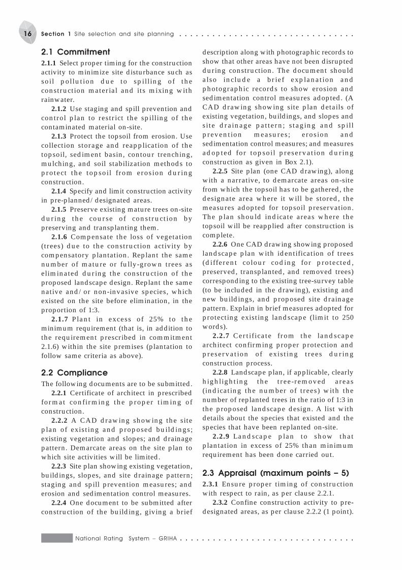
2.1 Commitment
2.1.1 Select proper timing for the constructionactivity to minimize site disturbance such assoil pollution due to spilling of theconstruction material and its mixing withrainwater.
2.1.2 Use staging and spill prevention andcontrol plan to restrict the spilling of thecontaminated material on-site.
2.1.3 Protect the topsoil from erosion. Usecollection storage and reapplication of thetopsoil, sediment basin, contour trenching,mulching, and soil stabilization methods toprotect the topsoil from erosion duringconstruction.
2.1.4 Specify and limit construction activityin pre-planned/designated areas.
2.1.5 Preserve existing mature trees on-siteduring the course of construction bypreserving and transplanting them.
2.1.6 Compensate the loss of vegetation(trees) due to the construction activity bycompensatory plantation. Replant the samenumber of mature or fully-grown trees aseliminated during the construction of theproposed landscape design. Replant the samenative and/or non-invasive species, whichexisted on the site before elimination, in theproportion of 1:3.
2.1.7 Plant in excess of 25% to theminimum requirement (that is, in addition tothe requirement prescribed in commitment2.1.6) within the site premises (plantation tofollow same criteria as above).
2.2 Compliance
The following documents are to be submitted.2.2.1 Certificate of architect in prescribed
format confirming the proper timing ofconstruction.
2.2.2 A CAD drawing showing the siteplan of existing and proposed buildings;existing vegetation and slopes; and drainagepattern. Demarcate areas on the site plan towhich site activities will be limited.
2.2.3 Site plan showing existing vegetation,buildings, slopes, and site drainage pattern;staging and spill prevention measures; anderosion and sedimentation control measures.
2.2.4 One document to be submitted afterconstruction of the building, giving a brief
description along with photographic records toshow that other areas have not been disruptedduring construction. The document shouldalso include a brief explanation andphotographic records to show erosion andsedimentation control measures adopted. (ACAD drawing showing site plan details ofexisting vegetation, buildings, and slopes andsite drainage pattern; staging and spillprevention measures; erosion andsedimentation control measures; and measuresadopted for topsoil preservation duringconstruction as given in Box 2.1).
2.2.5 Site plan (one CAD drawing), alongwith a narrative, to demarcate areas on-sitefrom which the topsoil has to be gathered, thedesignate area where it will be stored, themeasures adopted for topsoil preservation.The plan should indicate areas where thetopsoil will be reapplied after construction iscomplete.
2.2.6 One CAD drawing showing proposedlandscape plan with identification of trees(different colour coding for protected,preserved, transplanted, and removed trees)corresponding to the existing tree-survey table(to be included in the drawing), existing andnew buildings, and proposed site drainagepattern. Explain in brief measures adopted forprotecting existing landscape (limit to 250words).
2.2.7 Certificate from the landscapearchitect confirming proper protection andpreservation of existing trees duringconstruction process.
2.2.8 Landscape plan, if applicable, clearlyhighlighting the tree-removed areas(indicating the number of trees) with thenumber of replanted trees in the ratio of 1:3 inthe proposed landscape design. A list withdetails about the species that existed and thespecies that have been replanted on-site.
2.2.9 Landscape plan to show thatplantation in excess of 25% than minimumrequirement has been done carried out.
2.3 Appraisal (maximum points – 5)
2.3.1 Ensure proper timing of constructionwith respect to rain, as per clause 2.2.1.
2.3.2 Confine construction activity to pre-designated areas, as per clause 2.2.2 (1 point).

○ ○ ○ ○ ○ ○ ○ ○ ○ ○ ○ ○ ○ ○ ○ ○ ○ ○ ○ ○ ○ ○ ○ ○ ○ ○ ○ ○ ○ ○ ○ ○ National Rat ing System – GRIHA
17○ ○ ○ ○ ○ ○ ○ ○ ○ ○ ○ ○ ○ ○ ○ ○ ○ ○ ○ ○ ○ ○ ○ ○ ○ ○ ○ ○ ○ ○ ○ ○ Section 1: S i te select ion and s i te planning
2.3.3 Proper implementation of staging andspill prevention plan.
2.3.4 Effective erosion and sedimentationcontrol to prevent erosion, as per clause 2.2.3(1 point – mandatory).
2.3.5 Preserve topsoil by employingmeasures described in Box 2.1, as per clause2.2.4 (1 point).
2.3.6 Preserve existing vegetation by
means of non-disturbance or damage to treesand other forms of vegetation, as per clauses2.2.5 and 2.2.6 or
2.3.7 Trees/plants replanted within sitepremises in ratio of 1:3, as per clause 2.2.7(1 point – mandatory).
2.3.8 Trees/plants replanted within sitepremises in excess of 25% than minimumrequirement, as per clause 2.2.8 (1 point).
National Rat ing System – GRIHA ○ ○ ○ ○ ○ ○ ○ ○ ○ ○ ○ ○ ○ ○ ○ ○ ○ ○ ○ ○ ○ ○ ○ ○ ○ ○ ○ ○ ○ ○ ○ ○
18 Section 1 Si te select ion and s i te planning ○ ○ ○ ○ ○ ○ ○ ○ ○ ○ ○ ○ ○ ○ ○ ○ ○ ○ ○ ○ ○ ○ ○ ○ ○ ○ ○ ○ ○ ○ ○ ○
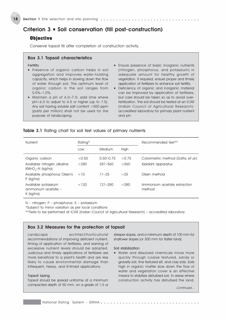
Criterion 3 P Soil conservation (till post-construction)
Objective
Conserve topsoil till after completion of construction activity.
Box 3.1 Topsoil characteristics
Fertility
P Presence of organic carbon helps in soi l
aggregation and improves water-holding
capacity, which helps in slowing down the flow
of water through soil. The optimum level of
organic carbon in the soi l ranges f rom
0.5%–1.0%.
P Maintain a pH of 6.0–7.5; add lime where
pH<6.0 to adjust to 6.5 or higher (up to 7.5).
Any soil having soluble salt content >500 ppm
(parts per million) shall not be used for the
purpose of landscaping.
P Ensure presence of basic inorganic nutrients
(ni t rogen, phosphorus, and potassium) in
adequate amount for healthy growth of
vegetation. If required, ensure proper and timely
application of fertilizers to enhance soil fertility.
P Deficiency of organic and inorganic material
can be improved by application of fertilizers,
but care should be taken so as to avoid over-
fertilization. The soil should be tested at an ICAR
(Indian Counci l of Agricultural Research)-
accredited laboratory for primary plant nutrient
and pH.
Box 3.2 Measures for the protection of topsoil
Landscape architect/hort icultur ist
recommendations of improving deficient nutrient,
timing of application of fertilizers, and warning of
excessive nutrient levels should be adopted.
Judicious and timely applications of fertilizers are
more beneficial to a plant’s health and are less
l ikely to cause environmental damage than
infrequent, heavy, and ill-timed applications.
Topsoil laying
Topsoil should be spread uniformly at a minimum
compacted depth of 50 mm, on a grade of 1:3 or
steeper slopes, and a minimum depth of 100 mm for
shallower slopes (or 300 mm for flatter land).
Soil stabilization
P Water and dissolved chemicals move more
quickly through coarse textured, sandy or
gravelly soil, fine textured silt, and clay soils. Soils
high in organic matter slow down the flow of
water and vegetation cover is an effective
means to stabilize disturbed soil. In areas where
construction activity has disturbed the land,
Table 3.1 Rating chart for soil test values of primary nutrients
Nutrient Rating* Recommended test**
Low Medium High
Organic carbon <0.50 0.50–0.75 >0.75 Colorimetric method (Datta et al.)
Available nitrogen alkaline <280 281–560 >560 Kjeldahl apparatus
KMnO4–N (kg/ha)
Available phosphorus Olsen’s <10 11–25 >25 Olsen method
P (kg/ha)
Available potassium <120 121–280 >280 Ammonium acetate extraction
ammonium acetate – method
K (kg/ha)
N – nitrogen; P – phosphorus; K – potassium
*Subject to minor variation as per local conditions
**Tests to be performed at ICAR (Indian Council of Agricultural Research) – accredited laboratory.
Continued...
○ ○ ○ ○ ○ ○ ○ ○ ○ ○ ○ ○ ○ ○ ○ ○ ○ ○ ○ ○ ○ ○ ○ ○ ○ ○ ○ ○ ○ ○ ○ ○ National Rat ing System – GRIHA
19○ ○ ○ ○ ○ ○ ○ ○ ○ ○ ○ ○ ○ ○ ○ ○ ○ ○ ○ ○ ○ ○ ○ ○ ○ ○ ○ ○ ○ ○ ○ ○ Section 1: S i te select ion and s i te planning
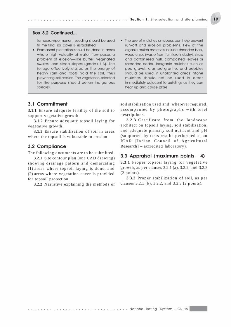
3.1 Commitment
3.1.1 Ensure adequate fertility of the soil tosupport vegetative growth.
3.1.2 Ensure adequate topsoil laying forvegetative growth.
3.1.3 Ensure stabilization of soil in areaswhere the topsoil is vulnerable to erosion.
3.2 Compliance
The following documents are to be submitted.3.2.1 Site contour plan (one CAD drawing)
showing drainage pattern and demarcating(1) areas where topsoil laying is done, and(2) areas where vegetation cover is providedfor topsoil protection.
3.2.2 Narrative explaining the methods of
soil stabilization used and, wherever required,accompanied by photographs with briefdescriptions.
3.2.3 Certificate from the landscapearchitect on topsoil laying, soil stabilization,and adequate primary soil nutrient and pH(supported by tests results performed at anICAR [Indian Council of AgriculturalResearch] – accredited laboratory).
3.3 Appraisal (maximum points – 4)
3.3.1 Proper topsoil laying for vegetativegrowth, as per clauses 3.2.1 (a), 3.2.2, and 3.2.3(2 points).
3.3.2 Proper stabilization of soil, as perclauses 3.2.1 (b), 3.2.2, and 3.2.3 (2 points).
Box 3.2 Continued...
temporary/permanent seeding should be used
till the final soil cover is established.
P Permanent plantation should be done in areas
where high velocity of water f low poses a
problem of erosion—like buffer, vegetated
swales, and steep slopes (grade>1:3). The
foliage effectively dissipates the energy of
heavy rain and roots hold the soi l , thus
preventing soil erosion. The vegetation selected
for the purpose should be an indigenous
species.
P The use of mulches on slopes can help prevent
run-off and erosion problems. Few of the
organic mulch materials include shredded bark,
wood chips (waste from furniture industry), straw
and cottonseed hull, composted leaves or
shredded cedar. Inorganic mulches such as
pea gravel, crushed granite, and pebbles
should be used in unplanted areas. Stone
mulches should not be used in areas
immediately adjacent to buildings as they can
heat up and cause glare.
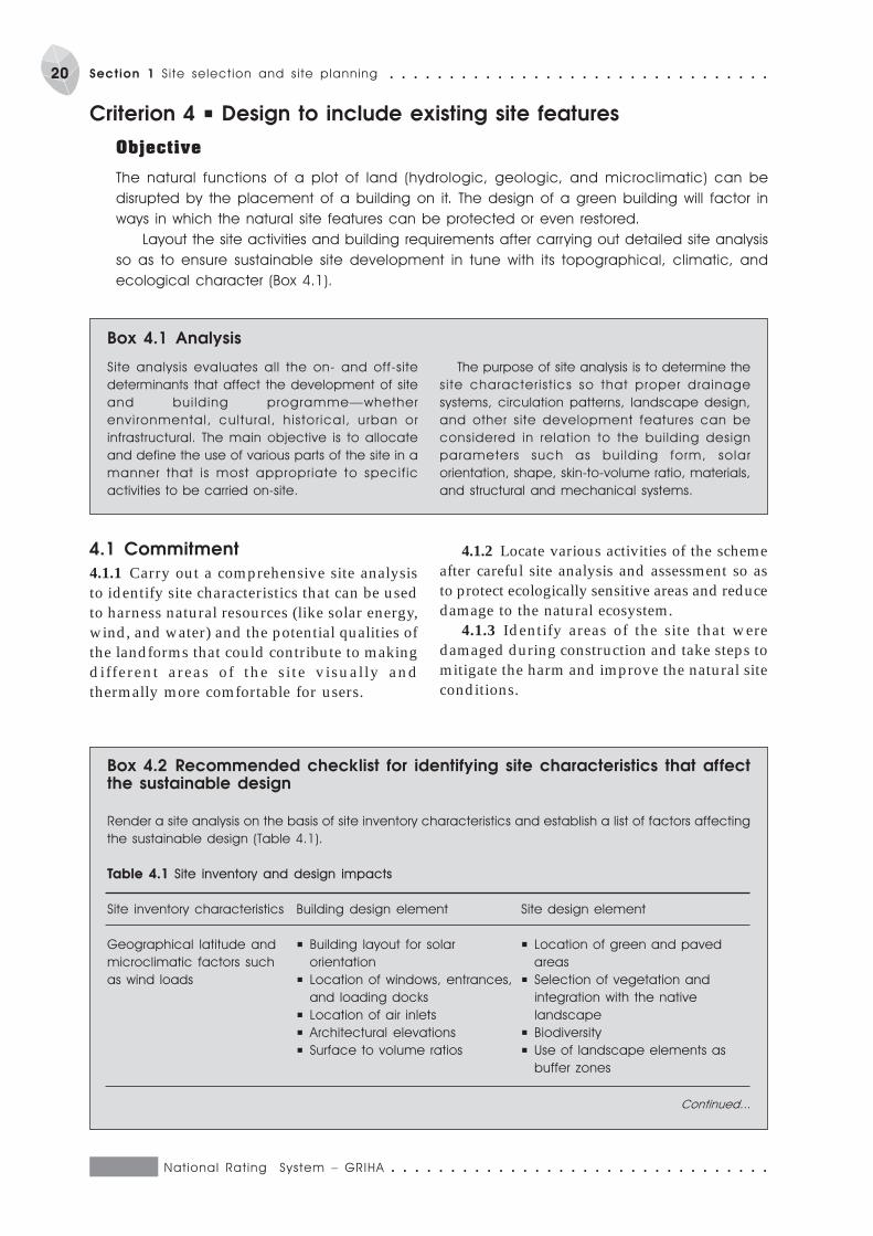
National Rat ing System – GRIHA ○ ○ ○ ○ ○ ○ ○ ○ ○ ○ ○ ○ ○ ○ ○ ○ ○ ○ ○ ○ ○ ○ ○ ○ ○ ○ ○ ○ ○ ○ ○ ○
20 Section 1 Si te select ion and s i te planning ○ ○ ○ ○ ○ ○ ○ ○ ○ ○ ○ ○ ○ ○ ○ ○ ○ ○ ○ ○ ○ ○ ○ ○ ○ ○ ○ ○ ○ ○ ○ ○
Criterion 4 P Design to include existing site features
Objective
The natural functions of a plot of land (hydrologic, geologic, and microclimatic) can be
disrupted by the placement of a building on it. The design of a green building will factor in
ways in which the natural site features can be protected or even restored.
Layout the site activities and building requirements after carrying out detailed site analysis
so as to ensure sustainable site development in tune with its topographical, climatic, and
ecological character (Box 4.1).
Box 4.1 Analysis
Site analysis evaluates all the on- and off-site
determinants that affect the development of site
and bui lding programme—whether
envi ronmental, cultural, histor ical, urban or
infrastructural. The main objective is to allocate
and define the use of various parts of the site in a
manner that is most appropriate to specif ic
activities to be carried on-site.
The purpose of site analysis is to determine the
site character ist ics so that proper drainage
systems, circulation patterns, landscape design,
and other site development features can be
considered in relation to the building design
parameters such as bui lding form, solar
orientation, shape, skin-to-volume ratio, materials,
and structural and mechanical systems.
4.1 Commitment
4.1.1 Carry out a comprehensive site analysisto identify site characteristics that can be usedto harness natural resources (like solar energy,wind, and water) and the potential qualities ofthe landforms that could contribute to makingdifferent areas of the site visually andthermally more comfortable for users.
4.1.2 Locate various activities of the schemeafter careful site analysis and assessment so asto protect ecologically sensitive areas and reducedamage to the natural ecosystem.
4.1.3 Identify areas of the site that weredamaged during construction and take steps tomitigate the harm and improve the natural siteconditions.
Box 4.2 Recommended checklist for identifying site characteristics that affectthe sustainable design
Render a site analysis on the basis of site inventory characteristics and establish a list of factors affecting
the sustainable design (Table 4.1).
Table 4.1 Site inventory and design impacts
Site inventory characteristics Building design element Site design element
Geographical latitude and P Building layout for solar P Location of green and paved
microclimatic factors such orientation areas
as wind loads P Location of windows, entrances, P Selection of vegetation and
and loading docks integration with the native
P Location of air inlets landscape
P Architectural elevations P Biodiversity
P Surface to volume ratios P Use of landscape elements as
buffer zones
Continued...
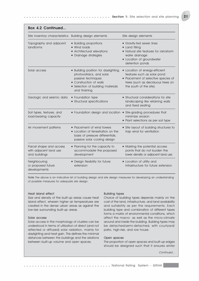
○ ○ ○ ○ ○ ○ ○ ○ ○ ○ ○ ○ ○ ○ ○ ○ ○ ○ ○ ○ ○ ○ ○ ○ ○ ○ ○ ○ ○ ○ ○ ○ National Rat ing System – GRIHA
21○ ○ ○ ○ ○ ○ ○ ○ ○ ○ ○ ○ ○ ○ ○ ○ ○ ○ ○ ○ ○ ○ ○ ○ ○ ○ ○ ○ ○ ○ ○ ○ Section 1: S i te select ion and s i te planning
Topography and adjacent P Building proportions P Gravity-fed sewer lines
landforms P Wind loads P Land filling
P Architectural elevations P Natural site features for rain/storm
P Drainage strategies water drainage
P Location of groundwater
detention ponds
Solar access P Building position for daylighting, P Location of energy-efficient
photovoltaics, and solar features such as solar pond
passive techniques P Placement of selective species of
P Construction of walls trees (such as deciduous trees on
P Selection of building materials the south of the site)
and finishing
Geologic and seismic data P Foundation type P Structural considerations for site
P Structural specifications landscaping like retaining walls
and fixed seating
Soil types, textures, and P Foundation design and location P Site-grading procedures that
load-bearing capacity minimize erosion
P Plant selections as per soil type
Air movement patterns P Placement of wind towers P Site layout of building structures to
P Location of fenestration on the trap wind for ventilation
basis of pressure differentials,
passive solar cooling design
Parcel shape and access P Planning for the capacity to P Marking the potential access
with adjacent land use accommodate the proposed points that do not burden the
and buildings development lower density or adjacent land use
Neighbouring P Design flexibility for future P Location of utility and
or proposed future extension infrastructure for future extension
developments
Note The above is an indicative list of building design and site design measures for developing an understanding
of possible measures for adequate site design.
Site inventory characteristics Building design elements Site design elements
Heat island effect
Size and density of the built-up areas cause heat
island effect, wherein higher air temperatures are
created in the dense urban areas as against the
low-rise surrounding built-up areas.
Solar access
Solar access in the morphology of clusters can be
understood in terms of utilization of direct (and not
reflected or diffused) solar radiation, mainly for
daylighting and heat gain. This defines the minimal
distances between the buildings and the relations
between built-up volume and open spaces.
Building types
Choice of building types depends mainly on the
cost of the land, infrastructure, and land availability
and suitability as per the requirements. Each
building type and combination of different types
forms a matrix of environmental conditions, which
affect the macro- as well as the micro-climate
around and inside the building. Building types may
be detached/semi-detached, with courtyard/
patio, high-rise, and row house.
Open spaces
The proportion of open spaces and built-up edges
should be designed such that it ensures winter
Continued...
Box 4.2 Continued...
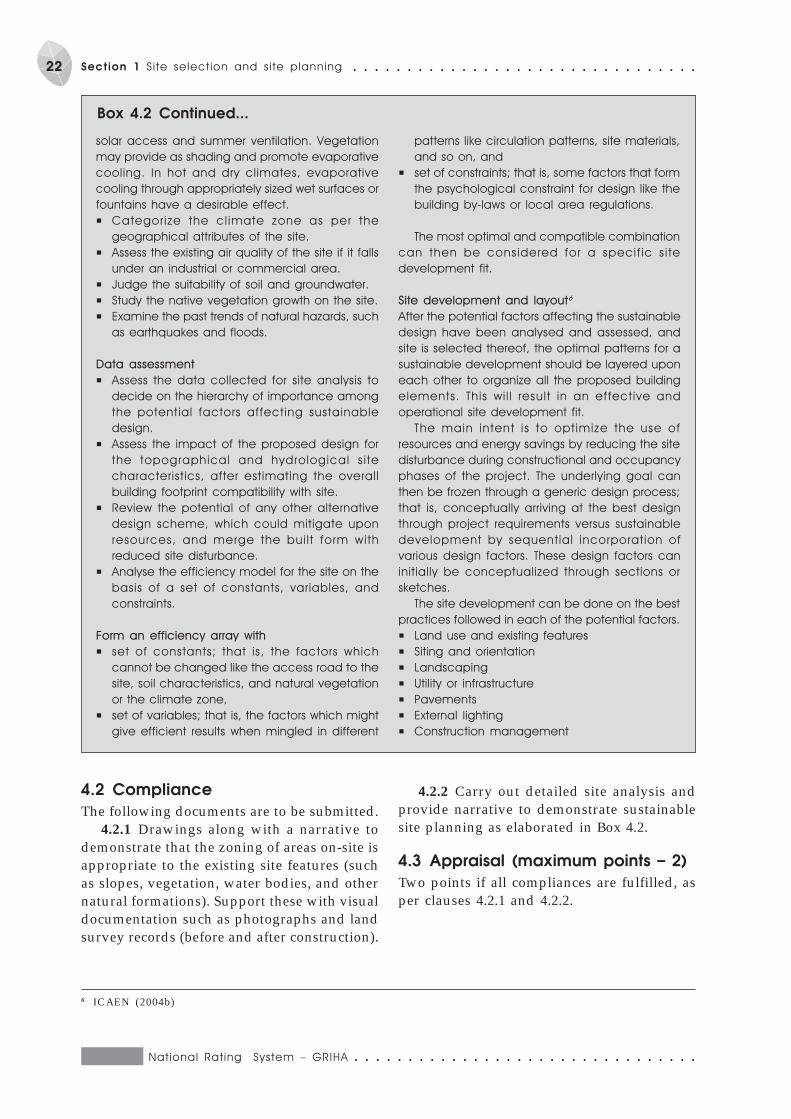
National Rat ing System – GRIHA ○ ○ ○ ○ ○ ○ ○ ○ ○ ○ ○ ○ ○ ○ ○ ○ ○ ○ ○ ○ ○ ○ ○ ○ ○ ○ ○ ○ ○ ○ ○ ○
22 Section 1 Si te select ion and s i te planning ○ ○ ○ ○ ○ ○ ○ ○ ○ ○ ○ ○ ○ ○ ○ ○ ○ ○ ○ ○ ○ ○ ○ ○ ○ ○ ○ ○ ○ ○ ○ ○
Box 4.2 Continued...
solar access and summer ventilation. Vegetation
may provide as shading and promote evaporative
cooling. In hot and dry climates, evaporative
cooling through appropriately sized wet surfaces or
fountains have a desirable effect.
P Categorize the cl imate zone as per the
geographical attributes of the site.
P Assess the existing air quality of the site if it falls
under an industrial or commercial area.
P Judge the suitability of soil and groundwater.
P Study the native vegetation growth on the site.
P Examine the past trends of natural hazards, such
as earthquakes and floods.
Data assessment
P Assess the data collected for site analysis to
decide on the hierarchy of importance among
the potential factors affecting sustainable
design.
P Assess the impact of the proposed design for
the topographical and hydrological s i te
characteristics, after estimating the overall
building footprint compatibility with site.
P Review the potential of any other alternative
design scheme, which could mitigate upon
resources, and merge the bui l t form with
reduced site disturbance.
P Analyse the efficiency model for the site on the
basis of a set of constants, variables, and
constraints.
Form an efficiency array with
P set of constants; that is, the factors which
cannot be changed like the access road to the
site, soil characteristics, and natural vegetation
or the climate zone,
P set of variables; that is, the factors which might
give efficient results when mingled in different
patterns like circulation patterns, site materials,
and so on, and
P set of constraints; that is, some factors that form
the psychological constraint for design like the
building by-laws or local area regulations.
The most optimal and compatible combination
can then be considered for a specif ic s i te
development fit.
Site development and layout6
After the potential factors affecting the sustainable
design have been analysed and assessed, and
site is selected thereof, the optimal patterns for a
sustainable development should be layered upon
each other to organize all the proposed building
elements. This wi l l result in an effective and
operational site development fit.
The main intent is to optimize the use of
resources and energy savings by reducing the site
disturbance during constructional and occupancy
phases of the project. The underlying goal can
then be frozen through a generic design process;
that is, conceptually arriving at the best design
through project requirements versus sustainable
development by sequential incorporation of
various design factors. These design factors can
initially be conceptualized through sections or
sketches.
The site development can be done on the best
practices followed in each of the potential factors.
P Land use and existing features
P Siting and orientation
P Landscaping
P Utility or infrastructure
P Pavements
P External lighting
P Construction management
6 ICAEN (2004b)
4.2 Compliance
The following documents are to be submitted.4.2.1 Drawings along with a narrative to
demonstrate that the zoning of areas on-site isappropriate to the existing site features (suchas slopes, vegetation, water bodies, and othernatural formations). Support these with visualdocumentation such as photographs and landsurvey records (before and after construction).
4.2.2 Carry out detailed site analysis andprovide narrative to demonstrate sustainablesite planning as elaborated in Box 4.2.
4.3 Appraisal (maximum points – 2)
Two points if all compliances are fulfilled, asper clauses 4.2.1 and 4.2.2.
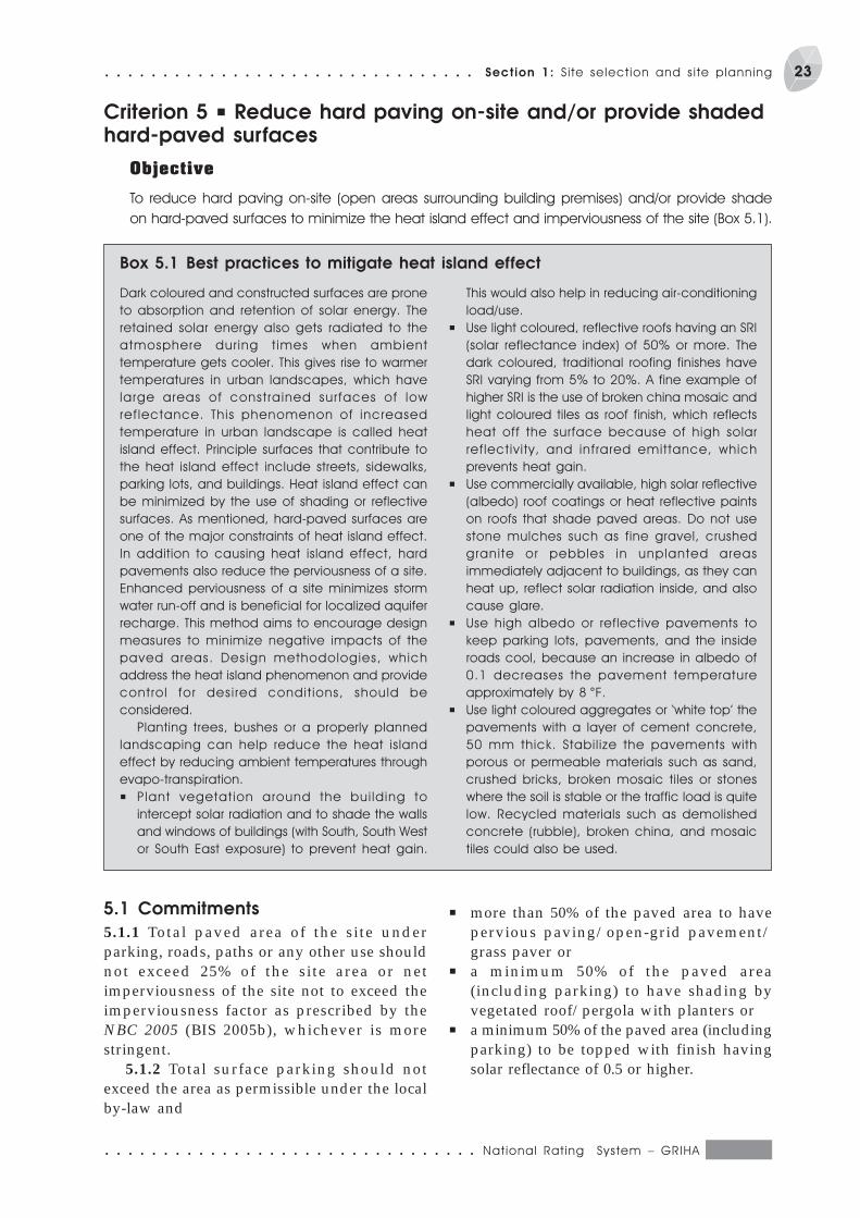
○ ○ ○ ○ ○ ○ ○ ○ ○ ○ ○ ○ ○ ○ ○ ○ ○ ○ ○ ○ ○ ○ ○ ○ ○ ○ ○ ○ ○ ○ ○ ○ National Rat ing System – GRIHA
23○ ○ ○ ○ ○ ○ ○ ○ ○ ○ ○ ○ ○ ○ ○ ○ ○ ○ ○ ○ ○ ○ ○ ○ ○ ○ ○ ○ ○ ○ ○ ○ Section 1: S i te select ion and s i te planning
Criterion 5 P Reduce hard paving on-site and/or provide shadedhard-paved surfaces
Objective
To reduce hard paving on-site (open areas surrounding building premises) and/or provide shade
on hard-paved surfaces to minimize the heat island effect and imperviousness of the site (Box 5.1).
Dark coloured and constructed surfaces are prone
to absorption and retention of solar energy. The
retained solar energy also gets radiated to the
atmosphere dur ing t imes when ambient
temperature gets cooler. This gives rise to warmer
temperatures in urban landscapes, which have
large areas of constrained surfaces of low
ref lectance. This phenomenon of increased
temperature in urban landscape is called heat
island effect. Principle surfaces that contribute to
the heat island effect include streets, sidewalks,
parking lots, and buildings. Heat island effect can
be minimized by the use of shading or reflective
surfaces. As mentioned, hard-paved surfaces are
one of the major constraints of heat island effect.
In addition to causing heat island effect, hard
pavements also reduce the perviousness of a site.
Enhanced perviousness of a site minimizes storm
water run-off and is beneficial for localized aquifer
recharge. This method aims to encourage design
measures to minimize negative impacts of the
paved areas. Design methodologies, which
address the heat island phenomenon and provide
control for desi red condit ions, should be
considered.
Planting trees, bushes or a properly planned
landscaping can help reduce the heat island
effect by reducing ambient temperatures through
evapo-transpiration.
P Plant vegetat ion around the bui lding to
intercept solar radiation and to shade the walls
and windows of buildings (with South, South West
or South East exposure) to prevent heat gain.
Box 5.1 Best practices to mitigate heat island effect
This would also help in reducing air-conditioning
load/use.
P Use light coloured, reflective roofs having an SRI
(solar reflectance index) of 50% or more. The
dark coloured, traditional roofing finishes have
SRI varying from 5% to 20%. A fine example of
higher SRI is the use of broken china mosaic and
light coloured tiles as roof finish, which reflects
heat off the surface because of high solar
reflectivity, and infrared emittance, which
prevents heat gain.
P Use commercially available, high solar reflective
(albedo) roof coatings or heat reflective paints
on roofs that shade paved areas. Do not use
stone mulches such as fine gravel, crushed
granite or pebbles in unplanted areas
immediately adjacent to buildings, as they can
heat up, reflect solar radiation inside, and also
cause glare.
P Use high albedo or reflective pavements to
keep parking lots, pavements, and the inside
roads cool, because an increase in albedo of
0.1 decreases the pavement temperature
approximately by 8 °F.
P Use light coloured aggregates or ‘white top’ the
pavements with a layer of cement concrete,
50 mm thick. Stabil ize the pavements with
porous or permeable materials such as sand,
crushed bricks, broken mosaic tiles or stones
where the soil is stable or the traffic load is quite
low. Recycled materials such as demolished
concrete (rubble), broken china, and mosaic
tiles could also be used.
5.1 Commitments
5.1.1 Total paved area of the site underparking, roads, paths or any other use shouldnot exceed 25% of the site area or netimperviousness of the site not to exceed theimperviousness factor as prescribed by theNBC 2005 (BIS 2005b), whichever is morestringent.
5.1.2 Total surface parking should notexceed the area as permissible under the localby-law and
P more than 50% of the paved area to havepervious paving/open-grid pavement/grass paver or
P a minimum 50% of the paved area(including parking) to have shading byvegetated roof/pergola with planters or
P a minimum 50% of the paved area (includingparking) to be topped with finish havingsolar reflectance of 0.5 or higher.
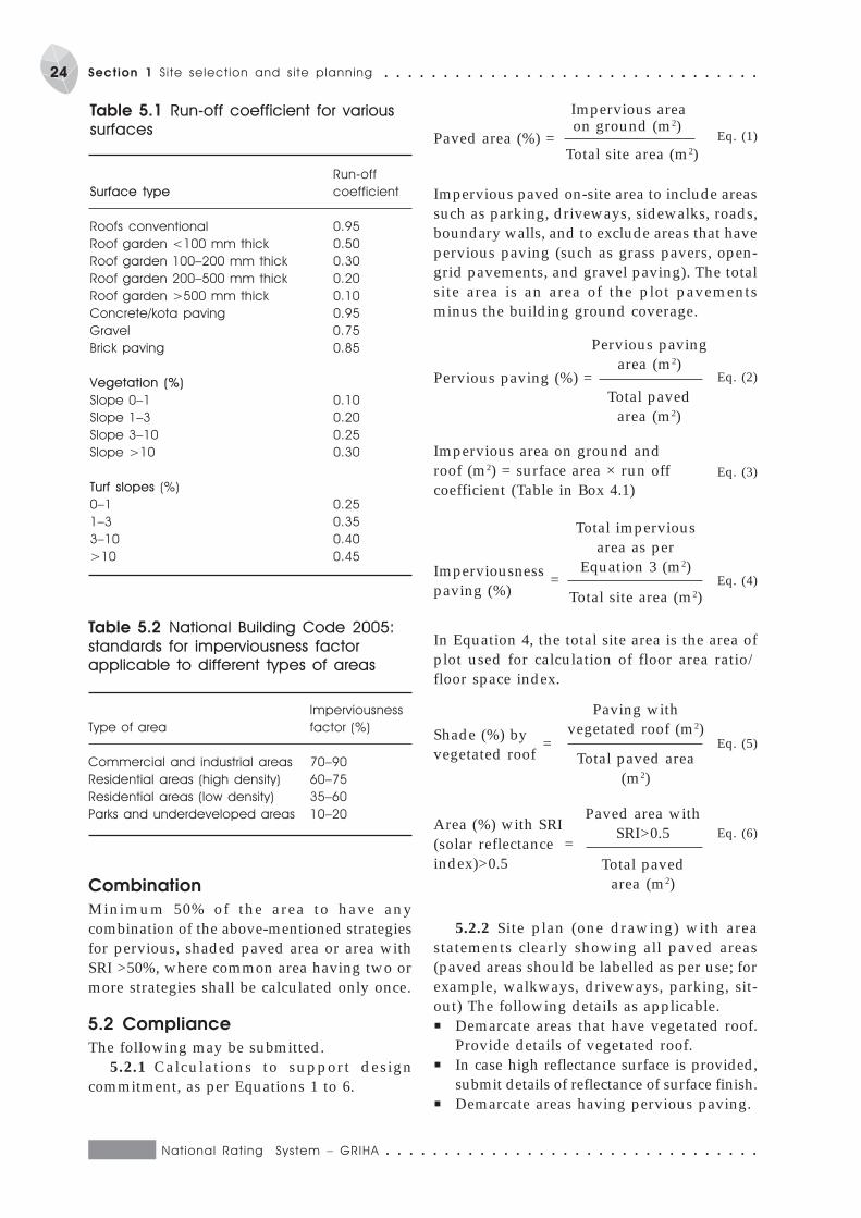
National Rat ing System – GRIHA ○ ○ ○ ○ ○ ○ ○ ○ ○ ○ ○ ○ ○ ○ ○ ○ ○ ○ ○ ○ ○ ○ ○ ○ ○ ○ ○ ○ ○ ○ ○ ○
24 Section 1 Si te select ion and s i te planning ○ ○ ○ ○ ○ ○ ○ ○ ○ ○ ○ ○ ○ ○ ○ ○ ○ ○ ○ ○ ○ ○ ○ ○ ○ ○ ○ ○ ○ ○ ○ ○
Table 5.2 National Building Code 2005:
standards for imperviousness factor
applicable to different types of areas
Imperviousness
Type of area factor (%)
Commercial and industrial areas 70–90
Residential areas (high density) 60–75
Residential areas (low density) 35–60
Parks and underdeveloped areas 10–20
Table 5.1 Run-off coefficient for various
surfaces
Run-off
Surface type coefficient
Roofs conventional 0.95
Roof garden <100 mm thick 0.50
Roof garden 100–200 mm thick 0.30
Roof garden 200–500 mm thick 0.20
Roof garden >500 mm thick 0.10
Concrete/kota paving 0.95
Gravel 0.75
Brick paving 0.85
Vegetation (%)
Slope 0–1 0.10
Slope 1–3 0.20
Slope 3–10 0.25
Slope >10 0.30
Turf slopes (%)
0–1 0.25
1–3 0.35
3–10 0.40
>10 0.45
Paved area (%) =
Impervious area
Eq. (1) on ground (m2)
Total site area (m2)
Impervious paved on-site area to include areassuch as parking, driveways, sidewalks, roads,boundary walls, and to exclude areas that havepervious paving (such as grass pavers, open-grid pavements, and gravel paving). The totalsite area is an area of the plot pavementsminus the building ground coverage.
Pervious paving (%) =
Pervious pavingarea (m2)
Total pavedarea (m2)
Eq. (2)
Impervious area on ground androof (m2) = surface area × run offcoefficient (Table in Box 4.1)
Eq. (3)
Imperviousness =paving (%)
Total imperviousarea as per
Equation 3 (m2)Eq. (4)
Total site area (m2)
Shade (%) by =vegetated roof
Paving withvegetated roof (m2)
Eq. (5)Total paved area
(m2)
Combination
Minimum 50% of the area to have anycombination of the above-mentioned strategiesfor pervious, shaded paved area or area withSRI >50%, where common area having two ormore strategies shall be calculated only once.
5.2 Compliance
The following may be submitted.5.2.1 Calculations to support design
commitment, as per Equations 1 to 6.
In Equation 4, the total site area is the area ofplot used for calculation of floor area ratio/floor space index.
Area (%) with SRI(solar reflectance =index)>0.5
Paved area withSRI>0.5 Eq. (6)
Total pavedarea (m2)
5.2.2 Site plan (one drawing) with areastatements clearly showing all paved areas(paved areas should be labelled as per use; forexample, walkways, driveways, parking, sit-out) The following details as applicable.P Demarcate areas that have vegetated roof.
Provide details of vegetated roof.P In case high reflectance surface is provided,
submit details of reflectance of surface finish.P Demarcate areas having pervious paving.

○ ○ ○ ○ ○ ○ ○ ○ ○ ○ ○ ○ ○ ○ ○ ○ ○ ○ ○ ○ ○ ○ ○ ○ ○ ○ ○ ○ ○ ○ ○ ○ National Rat ing System – GRIHA
25○ ○ ○ ○ ○ ○ ○ ○ ○ ○ ○ ○ ○ ○ ○ ○ ○ ○ ○ ○ ○ ○ ○ ○ ○ ○ ○ ○ ○ ○ ○ ○ Section 1: S i te select ion and s i te planning
5.2.3 Certificate from the architect tocertify that the total surface parking is aspermitted by local by-law.
5.3 Appraisal (maximum points – 2)
5.3.1 Total paved area of site under parking,roads, paths or any other use not to exceed25% of site area or net imperviousness of siteshould not exceed the imperviousness factor,as prescribed by NBC 2005 (BIS 2005b),whichever is more stringent, as per clauseEquations 1 and 4 (reference documents: 5.2.1and 5.2.2) (1 point).
5.3.2 Total surface parking not to exceed aspermitted by local by-law (mandatory) andP more than 50% of the paved area to have
pervious paving/open-grid pavement/grass paver (Equation 2) or
P minimum 50% of the paved area (includingparking) to have shading by vegetatedroof/pergola with planters (Equation 3) or
P minimum 50% of the paved area (includingparking) to be topped with solar reflectanceof 0.5 or higher (Equation 4) (1 point).(reference documents: 5.2.1 and 5.2.2).
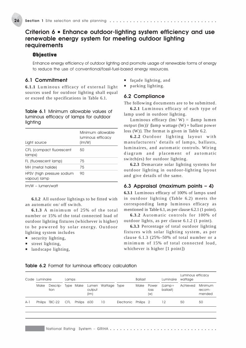
National Rat ing System – GRIHA ○ ○ ○ ○ ○ ○ ○ ○ ○ ○ ○ ○ ○ ○ ○ ○ ○ ○ ○ ○ ○ ○ ○ ○ ○ ○ ○ ○ ○ ○ ○ ○
26 Section 1 Si te select ion and s i te planning ○ ○ ○ ○ ○ ○ ○ ○ ○ ○ ○ ○ ○ ○ ○ ○ ○ ○ ○ ○ ○ ○ ○ ○ ○ ○ ○ ○ ○ ○ ○ ○
6.1 Commitment
6.1.1 Luminous efficacy of external lightsources used for outdoor lighting shall equalor exceed the specifications in Table 6.1.
Criterion 6 P Enhance outdoor-lighting system efficiency and userenewable energy system for meeting outdoor lightingrequirements
Objective
Enhance energy efficiency of outdoor lighting and promote usage of renewable forms of energy
to reduce the use of conventional/fossil-fuel-based energy resources.
Table 6.1 Minimum allowable values of
luminous efficacy of lamps for outdoor
lighting
Minimum allowable
luminous efficacy
Light source (lm/W)
CFL (compact fluorescent 50
lamps)
FL (fluorescent lamp) 75
MH (metal halide) 75
HPSV (high pressure sodium 90
vapour) lamp
lm/W – lumen/watt
6.1.2 All outdoor lightings to be fitted withan automatic on/off switch.
6.1.3 A minimum of 25% of the totalnumber or 15% of the total connected load ofoutdoor lighting fixtures (whichever is higher)to be powered by solar energy. Outdoorlighting system includesP security lighting,P street lighting,P landscape lighting,
P façade lighting, andP parking lighting.
6.2 Compliance
The following documents are to be submitted.6.2.1 Luminous efficacy of each type of
lamp used in outdoor lighting.Luminous efficacy (lm/W) = {lamp lumen
output (lm)}/{lamp wattage (W) + ballast powerloss (W)}. The format is given in Table 6.2.
6.2.2 Outdoor lighting layout withmanufacturers’ details of lamps, ballasts,luminaires, and automatic controls. Wiringdiagram and placement of automaticswitch(es) for outdoor lighting.
6.2.3 Demarcate solar lighting systems foroutdoor lighting in outdoor-lighting layoutand give details of the same.
6.3 Appraisal (maximum points – 4)
6.3.1 Luminous efficacy of 100% of lamps usedin outdoor lighting (Table 6.2) meets thecorresponding lamp luminous efficacy asmentioned in Table 6.1, as per clause 6.2.1 (1 point).
6.3.2 Automatic controls for 100% ofoutdoor lights, as per clause 6.1.2 (1 point).
6.3.3 Percentage of total outdoor lightingfixtures with solar lighting system, as perclause 6.1.3 (25%–50% of total number or aminimum of 15% of total connected load,whichever is higher [1 point])
Table 6.2 Format for luminous efficacy calculation
Luminous efficacy
Code Luminaire Lamps Ballast Luminaire wattage
Make Descrip- Type Make Lumen Wattage Type Make Power (Lamp+ Achieved Minimum
tion output loss ballast) recom-
(lm) (w) mended
A-1 Philips TBC-22 CFL Philips 600 10 Electronic Philips 2 12 50 50
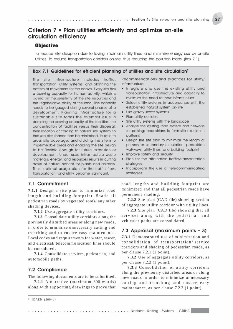
○ ○ ○ ○ ○ ○ ○ ○ ○ ○ ○ ○ ○ ○ ○ ○ ○ ○ ○ ○ ○ ○ ○ ○ ○ ○ ○ ○ ○ ○ ○ ○ National Rat ing System – GRIHA
27○ ○ ○ ○ ○ ○ ○ ○ ○ ○ ○ ○ ○ ○ ○ ○ ○ ○ ○ ○ ○ ○ ○ ○ ○ ○ ○ ○ ○ ○ ○ ○ Section 1: S i te select ion and s i te planning
Criterion 7 P Plan utilities efficiently and optimize on-sitecirculation efficiency
Objective
To reduce site disruption due to laying, maintain utility lines, and minimize energy use by on-site
utilities. To reduce transportation corridors on-site, thus reducing the pollution loads. (Box 7.1).
Box 7.1 Guidelines for efficient planning of utilities and site circulation7
The s i te inf rastructure includes t raff ic,
transportation, utility systems, and planning the
pattern of movement for the above. Every site has
a carrying capacity for human activity, which is
based on the sensitivity of the site resources and
the regenerative ability of the land. This capacity
needs to be gauged during several phases of a
development. Planning infrastructure for a
sustainable s i te forms the foremost issue in
deciding the carrying capacity of the facilities, the
concentration of facilities versus their dispersal,
their location according to natural site system so
that site disturbance can be minimized, its ratio to
gross site coverage, and dividing the site into
impermeable areas and enabling the site design
to be flexible enough for future extension or
development. Under-used infrastructure waste
materials, energy, and resources results in cutting
down of natural habitat for plants and animals.
Thus, optimal usage plan for the traffic flow,
transportation, and utility become significant.
Recommendations and practices for ut i l i ty/
infrastructure
P Integrate and use the exist ing ut i l i ty and
transportation infrastructure and capacity to
minimize the need for new infrastructure
P Select utility systems in accordance with the
established natural system on-site
P Use gravity sewer systems
P Plan utility corridors
P Site utility systems with the landscape
P Analyse the existing road system and networks
for parking; pedestrians to form site circulation
patterns
P Design the site plan to minimize the length of
primary or secondary circulation, pedestrian
walkways, utility lines, and building footprint
P Improve safety and security
P Plan for the alternative traffic/transportation
strategies
P Incorporate the use of telecommunicating
strategies
7.1 Commitment
7.1.1 Design a site plan to minimize roadlength and building footprint. Shade allpedestrian roads by vegetated roofs/any othershading devices.
7.1.2 Use aggregate utility corridors.7.1.3 Consolidate utility corridors along the
previously disturbed areas or along new roads,in order to minimize unnecessary cutting andtrenching and to ensure easy maintenance.Local codes and requirements for water, sewer,and electrical/telecommunication lines shouldbe considered.
7.1.4 Consolidate services, pedestrian, andautomobile paths.
7.2 Compliance
The following documents are to be submitted.7.2.1 A narrative (maximum 300 words)
along with supporting drawings to prove that
road lengths and building footprint areminimized and that all pedestrian roads havepermanent shading.
7.2.2 Site plan (CAD file) showing sectionof aggregate utility corridor with utility lines.
7.2.3 Site plan (CAD file) showing that allservices along with the pedestrian andvehicular paths are consolidated.
7.3 Appraisal (maximum points – 3)
7.3.1 Demonstrated use of minimization andconsolidation of transportation/servicecorridors and shading of pedestrian roads, asper clause 7.2.1 (1 point).
7.3.2 Use of aggregate utility corridors, asper clause 7.2.2 (1 point).
7.3.3 Consolidation of utility corridorsalong the previously disturbed areas or alongnew roads in order to minimize unnecessarycutting and trenching and ensure easymaintenance, as per clause 7.2.3 (1 point).
7 ICAEN (2004b)
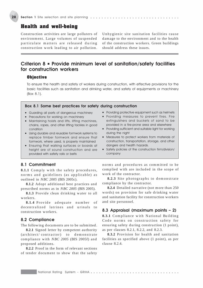
National Rat ing System – GRIHA ○ ○ ○ ○ ○ ○ ○ ○ ○ ○ ○ ○ ○ ○ ○ ○ ○ ○ ○ ○ ○ ○ ○ ○ ○ ○ ○ ○ ○ ○ ○ ○
28 Section 1 Si te select ion and s i te planning ○ ○ ○ ○ ○ ○ ○ ○ ○ ○ ○ ○ ○ ○ ○ ○ ○ ○ ○ ○ ○ ○ ○ ○ ○ ○ ○ ○ ○ ○ ○ ○
Health and well-being
Construction activities are large polluters ofenvironment. Large volumes of suspendedparticulate matters are released duringconstruction work leading to air pollution.
Unhygienic site sanitation facilities causedamage to the environment and to the healthof the construction workers. Green buildingsshould address these issues.
Criterion 8 P Provide minimum level of sanitation/safety facilitiesfor construction workers
Objective
To ensure the health and safety of workers during construction, with effective provisions for the
basic facilities such as sanitation and drinking water, and safety of equipments or machinery
(Box 8.1).
Box 8.1 Some best practices for safety during construction
P Guarding all parts of dangerous machinery
P Precautions for working on machinery
P Maintaining hoists and lifts, lifting machines,
chains, ropes, and other lifting tackles in good
condition
P Using durable and reusable formwork systems to
replace t imber formwork and ensure that
formwork, where used, is properly maintained
P Ensuring that walking surfaces or boards at
height are of sound construction and are
provided with safety rails or belts
P Providing protective equipment such as helmets
P Providing measures to prevent f i res. F i re
ext inguishers and buckets of sand to be
provided in a fire-prone area and elsewhere
P Providing sufficient and suitable light for working
during the night
P Measures to protect workers from materials of
construction, transportation, storage, and other
dangers and health hazards.
P Safety policies of the construction firm/division/
company
8.1 Commitment
8.1.1 Comply with the safety procedures,norms and guidelines (as applicable) asoutlined in NBC 2005 (BIS 2005c).
8.1.2 Adopt additional best practices andprescribed norms as in NBC 2005 (BIS 2005).
8.1.3 Provide clean drinking water to allworkers.
8.1.4 Provide adequate number ofdecentralized latrines and urinals toconstruction workers.
8.2 Compliance
The following documents are to be submitted.8.2.1 Signed letter by competent authority
(architect/contractor) to demonstratecompliance with NBC 2005 (BIS 2005f) andproposed additions.
8.2.2 Proof in the form of relevant sectionsof tender document to show that the safety
norms and procedures as committed to becomplied with are included in the scope ofwork of the contractor.
8.2.3 Site photographs to demonstratecompliance by the contractor.
8.2.4 Detailed narrative (not more than 250words) on provision for safe drinking waterand sanitation facility for construction workersand site personnel.
8.3 Appraisal (maximum points – 2)
8.3.1 Compliance with National BuildingCode norms on construction safety forensuring safety during construction (1 point),as per clauses 8.2.1, 8.2.2, and 8.2.3.
8.3.2 Provision for health and sanitationfacilities as specified above (1 point), as perclause 8.2.4.
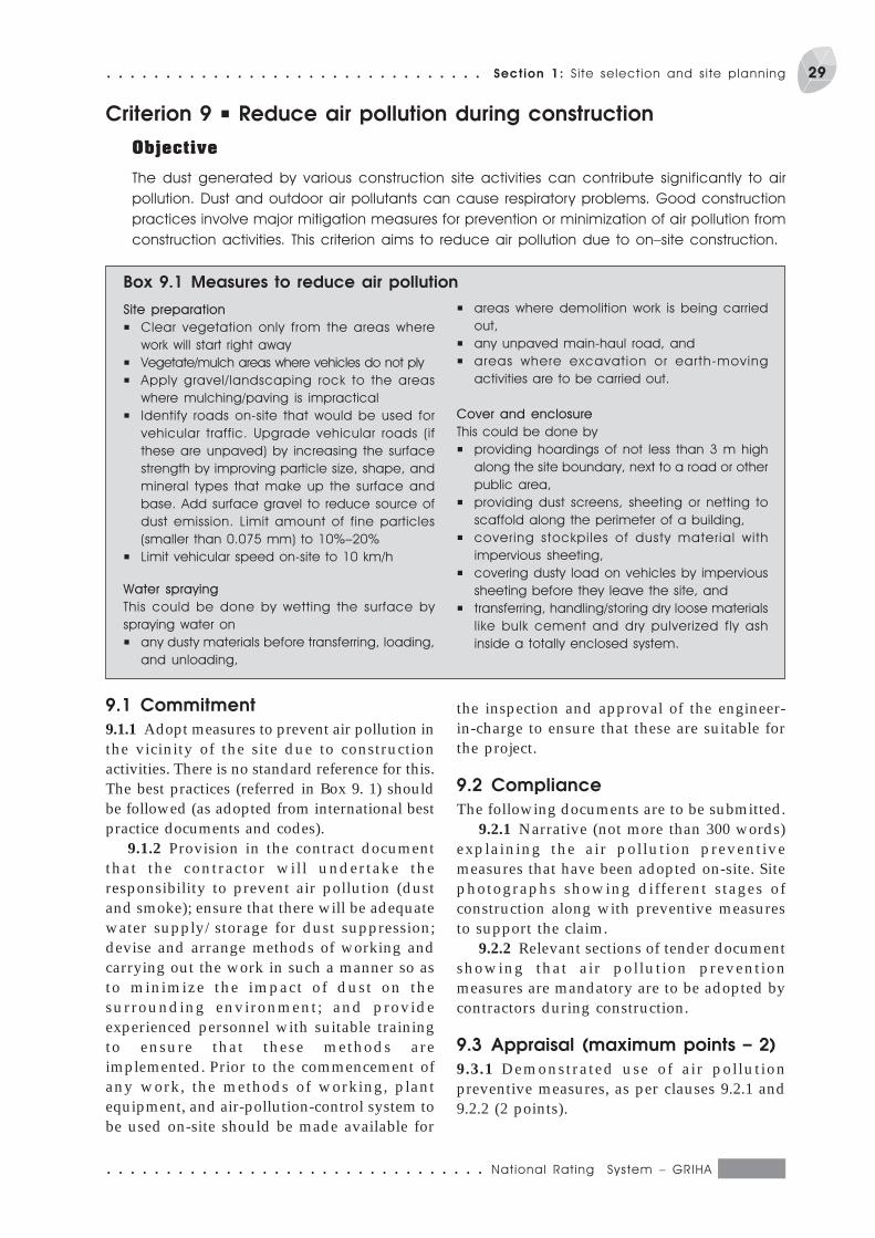
○ ○ ○ ○ ○ ○ ○ ○ ○ ○ ○ ○ ○ ○ ○ ○ ○ ○ ○ ○ ○ ○ ○ ○ ○ ○ ○ ○ ○ ○ ○ ○ National Rat ing System – GRIHA
29○ ○ ○ ○ ○ ○ ○ ○ ○ ○ ○ ○ ○ ○ ○ ○ ○ ○ ○ ○ ○ ○ ○ ○ ○ ○ ○ ○ ○ ○ ○ ○ Section 1: S i te select ion and s i te planning
Criterion 9 P Reduce air pollution during construction
Objective
The dust generated by various construction site activities can contribute significantly to air
pollution. Dust and outdoor air pollutants can cause respiratory problems. Good construction
practices involve major mitigation measures for prevention or minimization of air pollution from
construction activities. This criterion aims to reduce air pollution due to on–site construction.
Box 9.1 Measures to reduce air pollution
Site preparation
P Clear vegetation only from the areas where
work will start right away
P Vegetate/mulch areas where vehicles do not ply
P Apply gravel/landscaping rock to the areas
where mulching/paving is impractical
P Identify roads on-site that would be used for
vehicular traffic. Upgrade vehicular roads (if
these are unpaved) by increasing the surface
strength by improving particle size, shape, and
mineral types that make up the surface and
base. Add surface gravel to reduce source of
dust emission. Limit amount of fine particles
(smaller than 0.075 mm) to 10%–20%
P Limit vehicular speed on-site to 10 km/h
Water spraying
This could be done by wetting the surface by
spraying water on
P any dusty materials before transferring, loading,
and unloading,
P areas where demolition work is being carried
out,
P any unpaved main-haul road, and
P areas where excavation or earth-moving
activities are to be carried out.
Cover and enclosure
This could be done by
P providing hoardings of not less than 3 m high
along the site boundary, next to a road or other
public area,
P providing dust screens, sheeting or netting to
scaffold along the perimeter of a building,
P covering stockpi les of dusty material with
impervious sheeting,
P covering dusty load on vehicles by impervious
sheeting before they leave the site, and
P transferring, handling/storing dry loose materials
like bulk cement and dry pulverized fly ash
inside a totally enclosed system.
9.1 Commitment
9.1.1 Adopt measures to prevent air pollution inthe vicinity of the site due to constructionactivities. There is no standard reference for this.The best practices (referred in Box 9. 1) shouldbe followed (as adopted from international bestpractice documents and codes).
9.1.2 Provision in the contract documentthat the contractor will undertake theresponsibility to prevent air pollution (dustand smoke); ensure that there will be adequatewater supply/storage for dust suppression;devise and arrange methods of working andcarrying out the work in such a manner so asto minimize the impact of dust on thesurrounding environment; and provideexperienced personnel with suitable trainingto ensure that these methods areimplemented. Prior to the commencement ofany work, the methods of working, plantequipment, and air-pollution-control system tobe used on-site should be made available for
the inspection and approval of the engineer-in-charge to ensure that these are suitable forthe project.
9.2 Compliance
The following documents are to be submitted.9.2.1 Narrative (not more than 300 words)
explaining the air pollution preventivemeasures that have been adopted on-site. Sitephotographs showing different stages ofconstruction along with preventive measuresto support the claim.
9.2.2 Relevant sections of tender documentshowing that air pollution preventionmeasures are mandatory are to be adopted bycontractors during construction.
9.3 Appraisal (maximum points – 2)
9.3.1 Demonstrated use of air pollutionpreventive measures, as per clauses 9.2.1 and9.2.2 (2 points).

Criterion 10 P Reduce landscape water requirement
Objective
To reduce the landscape water requirement so as to minimize the load on the municipal water
supply and depletion of groundwater resources (Box 10.1).
S E C T I O N 2Building planning and
construction
Conservation and efficient
utilization of resources
Appropriate interventions at the planning anddesign stage can save valuable resources(water, energy, and materials) throughout thelife cycle of a building. The following criteriaaim to ensure saving such valuable resources.
An integrated approach to buildingplanning and construction is requiredto achieve maximum benefit in terms
of the environment. Appropriate interventionsat the design and construction stages arecritical to any sustainable building. Theseinterventions lead to reduced demand fordepletable resources and efficient resourceutilization. Options for recycling and reuse ofwaste adds to the sustainability of the buildingas a system.
10.1 Commitment
10.1.1 Design the landscape so as to reducewater consumption by 30% or more (up to50%).
10.2 Compliance
The following documents are to be submitted.10.2.1 Narrative demonstrating water
saving measures adopted in the landscapeplan.
10.2.2 Plan indicating the plants list, natureof species, and area covered.
10.2.3 Calculation of the water requirementafter establishment for landscape in LPD (litres
per day) for each month due to variation inPET (potential evapo-transpiration rate).
10.2.4 Provide cut sheets of the irrigationequipment showing technical specifications,such as flow rate and dimensions.
10.3 Appraisal (maximum points – 3)
10.3.1 Reduction in water consumption by30%, as per clause 10.2.3 (1 point).
10.3.2 Reduction in water consumption by40%, as per clause 10.2.3 (1 point).
10.3.3 Reduction in water consumption by50%, as per clause 10.2.3 (1 point).
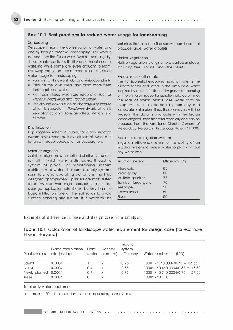
National Rat ing System – GRIHA ○ ○ ○ ○ ○ ○ ○ ○ ○ ○ ○ ○ ○ ○ ○ ○ ○ ○ ○ ○ ○ ○ ○ ○ ○ ○ ○ ○ ○ ○ ○ ○
32 Section 2: Bui lding planning and construct ion ○ ○ ○ ○ ○ ○ ○ ○ ○ ○ ○ ○ ○ ○ ○ ○ ○ ○ ○ ○ ○ ○ ○ ○ ○ ○ ○ ○ ○ ○
Xeriscaping
Xeriscape means the conservation of water and
energy through creative landscaping. This word is
derived from the Greek word, ‘Xeros’, meaning dry.
These plants can live with little or no supplemental
watering while some are even drought tolerant.
Following are some recommendations to reduce
water usage for landscaping.
P Pant a mix of native shrubs and xeriscape plants.
P Reduce the lawn area, and plant more trees
that require no water.
P Plant palm trees, which are xerophytic, such as
Phoenix dactylifera and Yucca starlite.
P Use ground covers such as Asparagus sprengeri,
which is succulent; Pandanus dwarf, which is
xerophyt ic; and Bougainvi l lea, which is a
climber.
Drip irrigation
Drip irrigation system or sub-surface drip irrigation
system saves water as it avoids loss of water due
to run-off, deep percolation or evaporation.
Sprinkler irrigation
Sprinkler irrigation is a method similar to natural
rainfall in which water is distributed through a
system of pipes. For maintaining uniform
distribution of water, the pump supply system,
sprinklers, and operating condit ions must be
designed appropriately. Sprinklers are most suited
to sandy soi ls with high inf i l t rat ion rates. The
average application rate should be less than the
basic infiltration rate of the soil so as to avoid
surface ponding and run-off. It is better to use
sprinklers that produce fine sprays than those that
produce larger water droplets.
Native vegetation
Native vegetation is original to a particular place,
including trees, shrubs, and other plants.
Evapo-transpiration rate
The PET (potential evapo-transpiration rate) is the
climate factor and refers to the amount of water
required by a plant for its healthy growth (depending
on the climate). Evapo-transpiration rate determines
the rate at which plants lose water through
evaporation. It is affected by humidity and
temperature at a given time. These rates vary with the
season. The data is available with the Indian
Meteorological Department for each city and can be
procured from the Additional Director General of
Meteorology (Research), Shivajinagar, Pune – 411 005.
Efficiencies of irrigation systems
Irr igation efficiency refers to the ability of an
irrigation system to deliver water to plants without
any water loss.
Irrigation system Efficiency (%)
Micro-drip 85
Micro-spray 80
Multiple sprinkler 75
Sprinkler, large guns 70
Seepage 50
Crown flood 50
Flood 50
Box 10.1 Best practices to reduce water usage for landscaping
Example of difference in base and design case from Jabalpur.
Table 10.1 Calculation of landscape water requirement for design case (for example,
Hissar, Haryana)
Irrigation
Evapo-transpiration Plant Canopy system
Plant species rate (m/day) factor area (m2) efficiency Water requirement (LPD)
Lawns 0.0004 1 x 0.75 1000*×*1*0.0004/0.75 = 53.33
Native 0.0004 0.4 x 0.85 1000*×*0.4*0.0004/0.85 = 18.82
Newly planted 0.0004 0.7 x 0.75 1000*×*0.7*0.0004/0.75 = 37.33
Trees 0.0004 0 x 1000*×*0 = 0
Total daily water requirement
m – metre; LPD – litres per day; x – corresponding conopy area

○ ○ ○ ○ ○ ○ ○ ○ ○ ○ ○ ○ ○ ○ ○ ○ ○ ○ ○ ○ ○ ○ ○ ○ ○ ○ ○ ○ ○ ○ ○ ○ National Rat ing System – GRIHA
33○ ○ ○ ○ ○ ○ ○ ○ ○ ○ ○ ○ ○ ○ ○ ○ ○ ○ ○ ○ ○ ○ ○ ○ ○ ○ ○ ○ ○ ○ Section 2: Bui lding planning and construct ion
Table 10.2 Calculation of landscape water requirement for base case (for example,
Hissar, Haryana)
Irrigation
Evapo-transpiration Plant Canopy system
Plant species rate (m/day) factor area (m2) efficiency Water requirement (LPD)
Lawns 0.0004 1 4x 0.75 1000*4x*1*0.0004/0.75 = 213.33
Total water requirement
Total daily water requirement (litres)
Total monthly water requirement (litres)
Total annual water requirement (litres)
Daily water requirement for base case (litres) = 1000*area of lawns (m2)*1*0.002/0.75
Monthly water requirement for base case (litres)
Annual water requirement for base case (litres)
Water use reduction (%) = [Annual water demand (base case) – annual water demand (design case) /
annual water demand (base case)] *100
Canopy area
Canopy area is square foot area of plant – view of the plant
a) assumed as 269 sq. ft. per tree and 162 numbers in an acre
b) assumed as area covered by shrubs and grass
Plant factor
Plant factor refers to the water requirement of plants. Plants are classified according to the resistance
to stress.
LPD – litres per day; m – metre
Table 10.3 Calculation of landscape water requirement for design case (for example,
Hissar, Haryana)
Evapo-transpiration Plant Canopy Irrigation system
Plant species rate (m/day) factor area (m2) efficiency Water requirement (LPD)
Lawns 0.002 1 100 0.75 1000*100*1*0.002/0.75
Native 0.002 0.4 100 0.85 1000*100*0.4*0.002/0.85
Newly planted 0.002 0.7 100 0.75 1000*100*0.7*0.002/0.75
Trees 0.002 0 100 0
Total water requirement
Total daily water requirement (litres)
Total monthly water requirement (litres)
Total annual water requirement (litres)
Daily water requirement for base case (litres) = 1000*area of lawns (m2)*1*0.002/0.75
Monthly water requirement for base case (litres)
Annual water requirement for base case (litres)
Water use reduction (%) = [Annual irrigation water requirement (base case – design case)/base case] * 100
Canopy area
Canopy area is square foot area of plant – view of the plant
a) assumed as 269 sq. ft. per tree and 162 numbers in an acre
b) assumed as area covered by shrubs and grass
Plant factor
Plant factor refers to the water requirement of plant. Plants are classified
according to the resistance to stress.
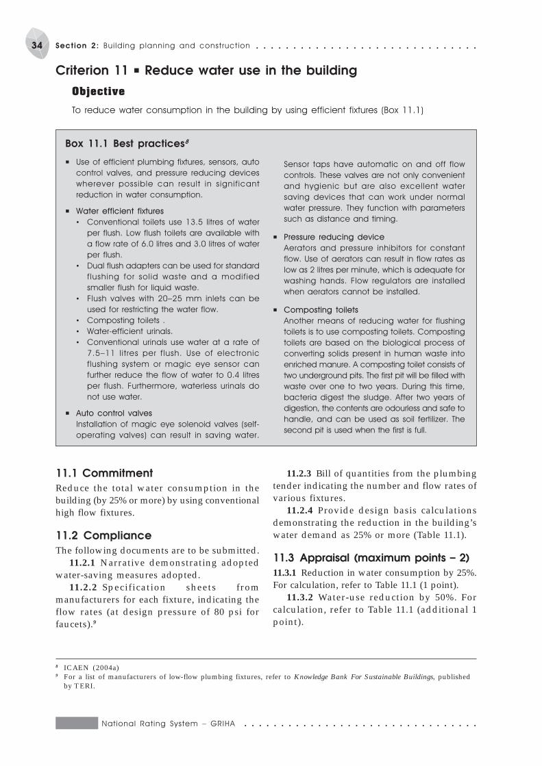
National Rat ing System – GRIHA ○ ○ ○ ○ ○ ○ ○ ○ ○ ○ ○ ○ ○ ○ ○ ○ ○ ○ ○ ○ ○ ○ ○ ○ ○ ○ ○ ○ ○ ○ ○ ○
34 Section 2: Bui lding planning and construct ion ○ ○ ○ ○ ○ ○ ○ ○ ○ ○ ○ ○ ○ ○ ○ ○ ○ ○ ○ ○ ○ ○ ○ ○ ○ ○ ○ ○ ○ ○
11.1 Commitment
Reduce the total water consumption in thebuilding (by 25% or more) by using conventionalhigh flow fixtures.
11.2 Compliance
The following documents are to be submitted.11.2.1 Narrative demonstrating adopted
water-saving measures adopted.11.2.2 Specification sheets from
manufacturers for each fixture, indicating theflow rates (at design pressure of 80 psi forfaucets).9
Criterion 11 P Reduce water use in the building
Objective
To reduce water consumption in the building by using efficient fixtures (Box 11.1)
11.2.3 Bill of quantities from the plumbingtender indicating the number and flow rates ofvarious fixtures.
11.2.4 Provide design basis calculationsdemonstrating the reduction in the building’swater demand as 25% or more (Table 11.1).
11.3 Appraisal (maximum points – 2)
11.3.1 Reduction in water consumption by 25%.For calculation, refer to Table 11.1 (1 point).
11.3.2 Water-use reduction by 50%. Forcalculation, refer to Table 11.1 (additional 1point).
P Use of efficient plumbing fixtures, sensors, auto
control valves, and pressure reducing devices
wherever possible can result in signif icant
reduction in water consumption.
P Water efficient fixtures
• Conventional toilets use 13.5 litres of water
per flush. Low flush toilets are available with
a flow rate of 6.0 litres and 3.0 litres of water
per flush.
• Dual flush adapters can be used for standard
flushing for sol id waste and a modif ied
smaller flush for liquid waste.
• Flush valves with 20–25 mm inlets can be
used for restricting the water flow.
• Composting toilets .
• Water-efficient urinals.
• Conventional urinals use water at a rate of
7.5–11 l itres per f lush. Use of electronic
flushing system or magic eye sensor can
further reduce the flow of water to 0.4 litres
per flush. Furthermore, waterless urinals do
not use water.
P Auto control valves
Installation of magic eye solenoid valves (self-
operating valves) can result in saving water.
Sensor taps have automatic on and off flow
controls. These valves are not only convenient
and hygienic but are also excellent water
saving devices that can work under normal
water pressure. They function with parameters
such as distance and timing.
P Pressure reducing device
Aerators and pressure inhibitors for constant
flow. Use of aerators can result in flow rates as
low as 2 litres per minute, which is adequate for
washing hands. Flow regulators are installed
when aerators cannot be installed.
P Composting toilets
Another means of reducing water for flushing
toilets is to use composting toilets. Composting
toilets are based on the biological process of
converting solids present in human waste into
enriched manure. A composting toilet consists of
two underground pits. The first pit will be filled with
waste over one to two years. During this time,
bacteria digest the sludge. After two years of
digestion, the contents are odourless and safe to
handle, and can be used as soil fertilizer. The
second pit is used when the first is full.
Box 11.1 Best practices8
8 ICAEN (2004a)9 For a list of manufacturers of low-flow plumbing fixtures, refer to Knowledge Bank For Sustainable Buildings, published
by TERI.
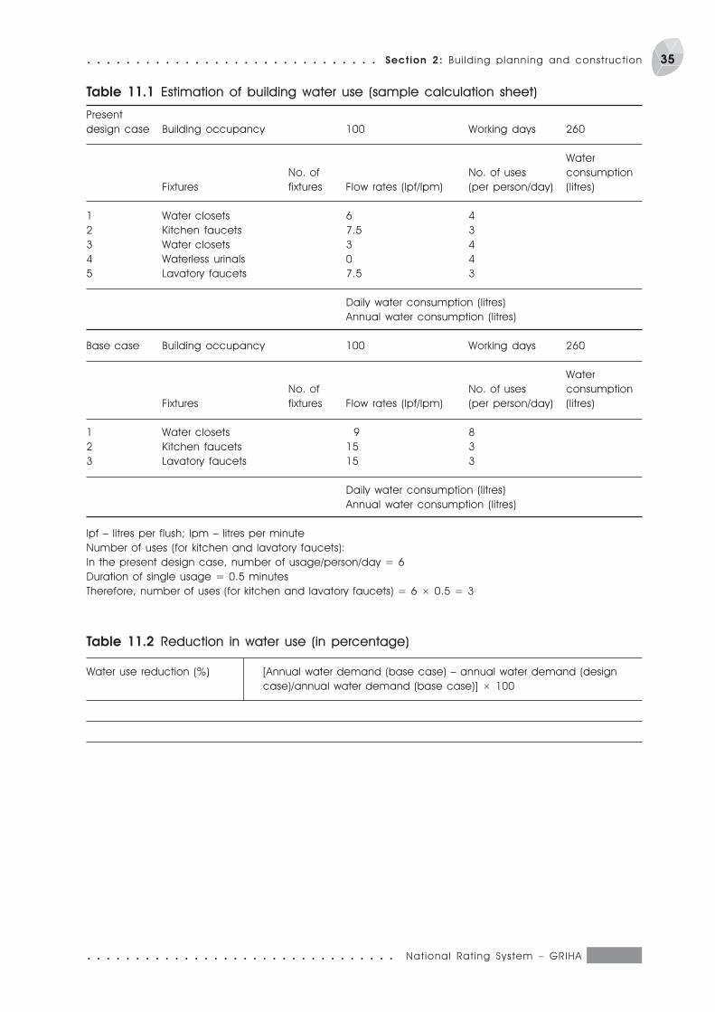
○ ○ ○ ○ ○ ○ ○ ○ ○ ○ ○ ○ ○ ○ ○ ○ ○ ○ ○ ○ ○ ○ ○ ○ ○ ○ ○ ○ ○ ○ ○ ○ National Rat ing System – GRIHA
35○ ○ ○ ○ ○ ○ ○ ○ ○ ○ ○ ○ ○ ○ ○ ○ ○ ○ ○ ○ ○ ○ ○ ○ ○ ○ ○ ○ ○ ○ Section 2: Bui lding planning and construct ion
Table 11.1 Estimation of building water use (sample calculation sheet)
Present
design case Building occupancy 100 Working days 260
Water
No. of No. of uses consumption
Fixtures fixtures Flow rates (lpf/lpm) (per person/day) (litres)
1 Water closets 6 4
2 Kitchen faucets 7.5 3
3 Water closets 3 4
4 Waterless urinals 0 4
5 Lavatory faucets 7.5 3
Daily water consumption (litres)
Annual water consumption (litres)
Base case Building occupancy 100 Working days 260
Water
No. of No. of uses consumption
Fixtures fixtures Flow rates (lpf/lpm) (per person/day) (litres)
1 Water closets 9 8
2 Kitchen faucets 15 3
3 Lavatory faucets 15 3
Daily water consumption (litres)
Annual water consumption (litres)
lpf – litres per flush; lpm – litres per minute
Number of uses (for kitchen and lavatory faucets):
In the present design case, number of usage/person/day = 6
Duration of single usage = 0.5 minutes
Therefore, number of uses (for kitchen and lavatory faucets) = 6 × 0.5 = 3
Table 11.2 Reduction in water use (in percentage)
Water use reduction (%) [Annual water demand (base case) – annual water demand (design
case)/annual water demand (base case)] × 100
National Rat ing System – GRIHA ○ ○ ○ ○ ○ ○ ○ ○ ○ ○ ○ ○ ○ ○ ○ ○ ○ ○ ○ ○ ○ ○ ○ ○ ○ ○ ○ ○ ○ ○ ○ ○
36 Section 2: Bui lding planning and construct ion ○ ○ ○ ○ ○ ○ ○ ○ ○ ○ ○ ○ ○ ○ ○ ○ ○ ○ ○ ○ ○ ○ ○ ○ ○ ○ ○ ○ ○ ○
12.1 Commitment
12.1.1 Use materials such as pre-mixedconcrete for preventing water loss duringmixing.
12.1.2 Use recycled treated water.12.1.3 Control the waste of curing water
(Box 12.1).
12.2 Compliance
The following documents are to be submitted.12.2.1 Certificate from architect confirming
the initiatives taken to minimize the use ofpotable water during construction.
Criterion 12 P Efficient water use during construction
Objective
To minimize use of potable water during construction.
The following are guidelines to avoid wastage of
curing water.
P Curing chemicals should be sprayed on
concrete structures and free flowing water
should not be cured.
P After cur ing on the f i rst day, al l concrete
structures should be painted with cur ing
chemicals. This will stop daily water curing and
save water.
Box 12.1 Controlling waste of curing water
P Water should be sprayed on concrete structures
after covering them with cloth/gunny bags. This
decreases water rebound and ensures sustained
and complete curing.
P Ponds should be made using cement and sand
mortar to avoid water flowing away from the flat
surface while curing.
P Water ponding should be done on all sunken
slabs. This also highlights the importance of
having an impervious formwork.
12.2.2 Narrative on the initiatives of wateruse minimization, indicating the varioussources of water.
12.3 Appraisal ( maximum points – 1)
12.3.1 Efforts to minimize potable water usefor construction, as per clauses 11.2.1 and12.2.2 (1 point).
Note This point is completely subject to theevaluator’s discretion
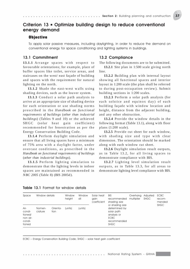
○ ○ ○ ○ ○ ○ ○ ○ ○ ○ ○ ○ ○ ○ ○ ○ ○ ○ ○ ○ ○ ○ ○ ○ ○ ○ ○ ○ ○ ○ ○ ○ National Rat ing System – GRIHA
37○ ○ ○ ○ ○ ○ ○ ○ ○ ○ ○ ○ ○ ○ ○ ○ ○ ○ ○ ○ ○ ○ ○ ○ ○ ○ ○ ○ ○ ○ Section 2: Bui lding planning and construct ion
Criterion 13 P Optimize building design to reduce conventionalenergy demand
Objective
To apply solar passive measures, including daylighting, in order to reduce the demand on
conventional energy for space conditioning and lighting systems in buildings.
13.1 Commitment
13.1.1 Arrange spaces with respect tofavourable orientations; for example, place ofbuffer spaces like toilet, service areas, andstaircases on the west/east façade of buildingand spaces with the requirement for naturallighting on the north.
13.1.2 Shade the east-west walls usingshading devices, such as the louver system.
13.1.3 Conduct a solar path analysis toarrive at an appropriate size of shading devicefor each orientation or use shading normsprescribed in the Handbook on functionalrequirements of buildings (other than industrialbuildings) (Tables 9 and 10) or the achievedSHGC (solar heat gain coefficient)recommended for fenestration as per theEnergy Conservation Building Code.
13.1.4 Perform daylight simulation andensure that all living spaces have a minimumof 75% area with a daylight factor, underovercast conditions, as prescribed in theHandbook on functional requirements of buildings(other than industrial buildings).
13.1.5 Perform lighting simulation todemonstrate that the lighting levels in indoorspaces are maintained as recommended inNBC 2005 (Table 8) (BIS 2005d).
13.2 Compliance
The following documents are to be submitted.13.2.1 Site plan in 1:500 scale giving north
line.13.2.2 Building plan with internal layout
showing all functional spaces and interiorlayout in 1:200 scale (the plan shall be referredto during post-occupation review). Submitbuilding sections in 1:200 scales.
13.2.3 Perform a solar path analysis (foreach solstice and equinox day) of eachbuilding façade with window location andheight, distance from the adjacent building,and any other obstruction.
13.2.4 Provide the window details in thefollowing format (Table 13.1), along with floorplans (1:200 scale).
13.2.5 Provide cut sheet for each window,with shading size and type with cleardimension. The orientation should be markedalong with each window cut sheet.
13.2.6 Daylight simulation result outputs,as in Table 13.2, for all living spaces todemonstrate compliance with BIS.
13.2.7 Lighting level simulation resultoutputs, as in Table 13.3, for all areas todemonstrate lighting level compliance with BIS.
Table 13.1 Format for window details
Space Window details Window Window Solar heat BIS Overhang Adjusted ECBC
height sill gain recommended multiplier SHGC recom-
coefficient shading size mended
or shading size SHGC
Air- Nomen- Orienta- (units) (units) determined by
condi- clature tion solar path
tioned/ analysis or
non air- ECBC
condi- recommended
tioned SHGC
ECBC – Energy Conservation Building Code; SHGC – solar heat gain coefficient
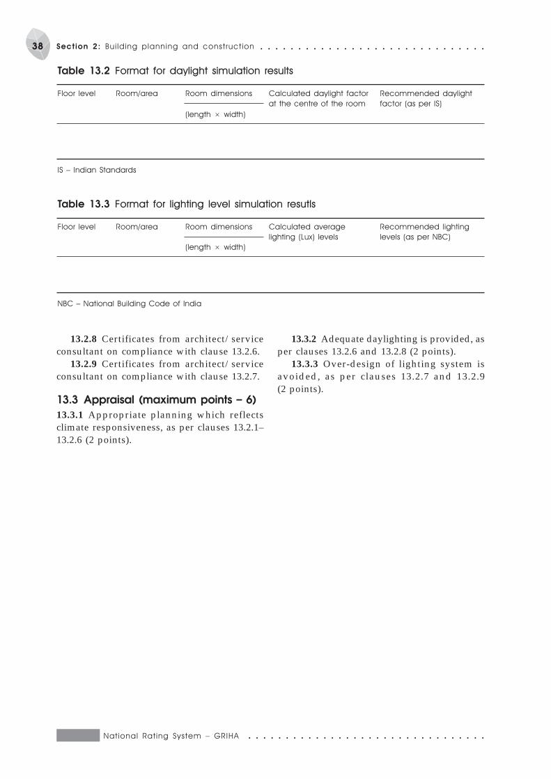
National Rat ing System – GRIHA ○ ○ ○ ○ ○ ○ ○ ○ ○ ○ ○ ○ ○ ○ ○ ○ ○ ○ ○ ○ ○ ○ ○ ○ ○ ○ ○ ○ ○ ○ ○ ○
38 Section 2: Bui lding planning and construct ion ○ ○ ○ ○ ○ ○ ○ ○ ○ ○ ○ ○ ○ ○ ○ ○ ○ ○ ○ ○ ○ ○ ○ ○ ○ ○ ○ ○ ○ ○
13.2.8 Certificates from architect/serviceconsultant on compliance with clause 13.2.6.
13.2.9 Certificates from architect/serviceconsultant on compliance with clause 13.2.7.
13.3 Appraisal (maximum points – 6)
13.3.1 Appropriate planning which reflectsclimate responsiveness, as per clauses 13.2.1–13.2.6 (2 points).
Table 13.2 Format for daylight simulation results
Floor level Room/area Room dimensions Calculated daylight factor Recommended daylight
at the centre of the room factor (as per IS)
(length × width)
IS – Indian Standards
Table 13.3 Format for lighting level simulation resutls
Floor level Room/area Room dimensions Calculated average Recommended lighting
lighting (Lux) levels levels (as per NBC)
(length × width)
NBC – National Building Code of India
13.3.2 Adequate daylighting is provided, asper clauses 13.2.6 and 13.2.8 (2 points).
13.3.3 Over-design of lighting system isavoided, as per clauses 13.2.7 and 13.2.9(2 points).
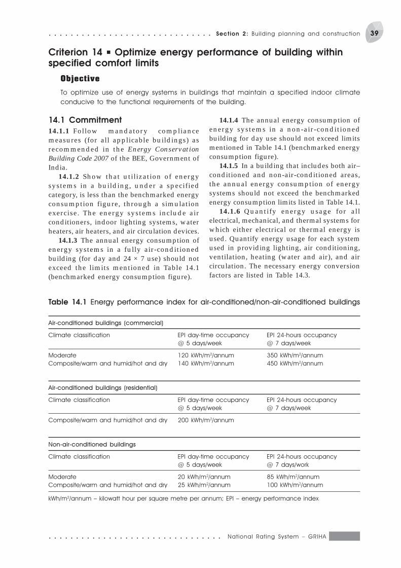
○ ○ ○ ○ ○ ○ ○ ○ ○ ○ ○ ○ ○ ○ ○ ○ ○ ○ ○ ○ ○ ○ ○ ○ ○ ○ ○ ○ ○ ○ ○ ○ National Rat ing System – GRIHA
39○ ○ ○ ○ ○ ○ ○ ○ ○ ○ ○ ○ ○ ○ ○ ○ ○ ○ ○ ○ ○ ○ ○ ○ ○ ○ ○ ○ ○ ○ Section 2: Bui lding planning and construct ion
Criterion 14 P Optimize energy performance of building withinspecified comfort limits
Objective
To optimize use of energy systems in buildings that maintain a specified indoor climate
conducive to the functional requirements of the building.
14.1 Commitment
14.1.1 Follow mandatory compliancemeasures (for all applicable buildings) asrecommended in the Energy ConservationBuilding Code 2007 of the BEE, Government ofIndia.
14.1.2 Show that utilization of energysystems in a building, under a specifiedcategory, is less than the benchmarked energyconsumption figure, through a simulationexercise. The energy systems include airconditioners, indoor lighting systems, waterheaters, air heaters, and air circulation devices.
14.1.3 The annual energy consumption ofenergy systems in a fully air-conditionedbuilding (for day and 24 × 7 use) should notexceed the limits mentioned in Table 14.1(benchmarked energy consumption figure).
14.1.4 The annual energy consumption ofenergy systems in a non-air-conditionedbuilding for day use should not exceed limitsmentioned in Table 14.1 (benchmarked energyconsumption figure).
14.1.5 In a building that includes both air–conditioned and non-air-conditioned areas,the annual energy consumption of energysystems should not exceed the benchmarkedenergy consumption limits listed in Table 14.1.
14.1.6 Quantify energy usage for allelectrical, mechanical, and thermal systems forwhich either electrical or thermal energy isused. Quantify energy usage for each systemused in providing lighting, air conditioning,ventilation, heating (water and air), and aircirculation. The necessary energy conversionfactors are listed in Table 14.3.
Table 14.1 Energy performance index for air-conditioned/non-air-conditioned buildings
Air-conditioned buildings (commercial)
Climate classification EPI day-time occupancy EPI 24-hours occupancy
@ 5 days/week @ 7 days/week
Moderate 120 kWh/m2/annum 350 kWh/m2/annum
Composite/warm and humid/hot and dry 140 kWh/m2/annum 450 kWh/m2/annum
Air-conditioned buildings (residential)
Climate classification EPI day-time occupancy EPI 24-hours occupancy
@ 5 days/week @ 7 days/week
Composite/warm and humid/hot and dry 200 kWh/m2/annum
Non-air-conditioned buildings
Climate classification EPI day-time occupancy EPI 24-hours occupancy
@ 5 days/week @ 7 days/work
Moderate 20 kWh/m2/annum 85 kWh/m2/annum
Composite/warm and humid/hot and dry 25 kWh/m2/annum 100 kWh/m2/annum
kWh/m2/annum – kilowatt hour per square metre per annum; EPI – energy performance index
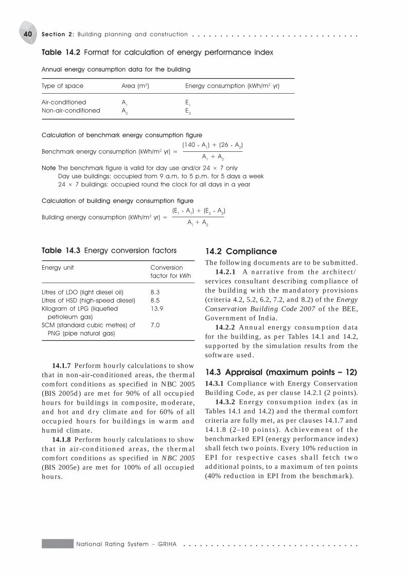
National Rat ing System – GRIHA ○ ○ ○ ○ ○ ○ ○ ○ ○ ○ ○ ○ ○ ○ ○ ○ ○ ○ ○ ○ ○ ○ ○ ○ ○ ○ ○ ○ ○ ○ ○ ○
40 Section 2: Bui lding planning and construct ion ○ ○ ○ ○ ○ ○ ○ ○ ○ ○ ○ ○ ○ ○ ○ ○ ○ ○ ○ ○ ○ ○ ○ ○ ○ ○ ○ ○ ○ ○
Table 14.2 Format for calculation of energy performance index
Annual energy consumption data for the building
Type of space Area (m2) Energy consumption (kWh/m2 yr)
Air-conditioned A1
E1
Non-air-conditioned A2
E2
Calculation of benchmark energy consumption figure
Benchmark energy consumption (kWh/m2 yr) = (140 × A
1) + (26 × A
2)
A
1 + A
2
Note The benchmark figure is valid for day use and/or 24 × 7 only
Day use buildings: occupied from 9 a.m. to 5 p.m. for 5 days a week
24 × 7 buildings: occupied round the clock for all days in a year
Calculation of building energy consumption figure
Building energy consumption (kWh/m2 yr) = (E
1 × A
1) + (E
2 × A
2)
A
1 + A
2
Table 14.3 Energy conversion factors
Energy unit Conversion
factor for kWh
Litres of LDO (light diesel oil) 8.3
Litres of HSD (high-speed diesel) 8.5
Kilogram of LPG (liquefied 13.9
petroleum gas)
SCM (standard cubic metres) of 7.0
PNG (pipe natural gas)
14.1.7 Perform hourly calculations to showthat in non-air-conditioned areas, the thermalcomfort conditions as specified in NBC 2005(BIS 2005d) are met for 90% of all occupiedhours for buildings in composite, moderate,and hot and dry climate and for 60% of alloccupied hours for buildings in warm andhumid climate.
14.1.8 Perform hourly calculations to showthat in air-conditioned areas, the thermalcomfort conditions as specified in NBC 2005(BIS 2005e) are met for 100% of all occupiedhours.
14.2 Compliance
The following documents are to be submitted.14.2.1 A narrative from the architect/
services consultant describing compliance ofthe building with the mandatory provisions(criteria 4.2, 5.2, 6.2, 7.2, and 8.2) of the EnergyConservation Building Code 2007 of the BEE,Government of India.
14.2.2 Annual energy consumption datafor the building, as per Tables 14.1 and 14.2,supported by the simulation results from thesoftware used.
14.3 Appraisal (maximum points – 12)
14.3.1 Compliance with Energy ConservationBuilding Code, as per clause 14.2.1 (2 points).
14.3.2 Energy consumption index (as inTables 14.1 and 14.2) and the thermal comfortcriteria are fully met, as per clauses 14.1.7 and14.1.8 (2–10 points). Achievement of thebenchmarked EPI (energy performance index)shall fetch two points. Every 10% reduction inEPI for respective cases shall fetch twoadditional points, to a maximum of ten points(40% reduction in EPI from the benchmark).
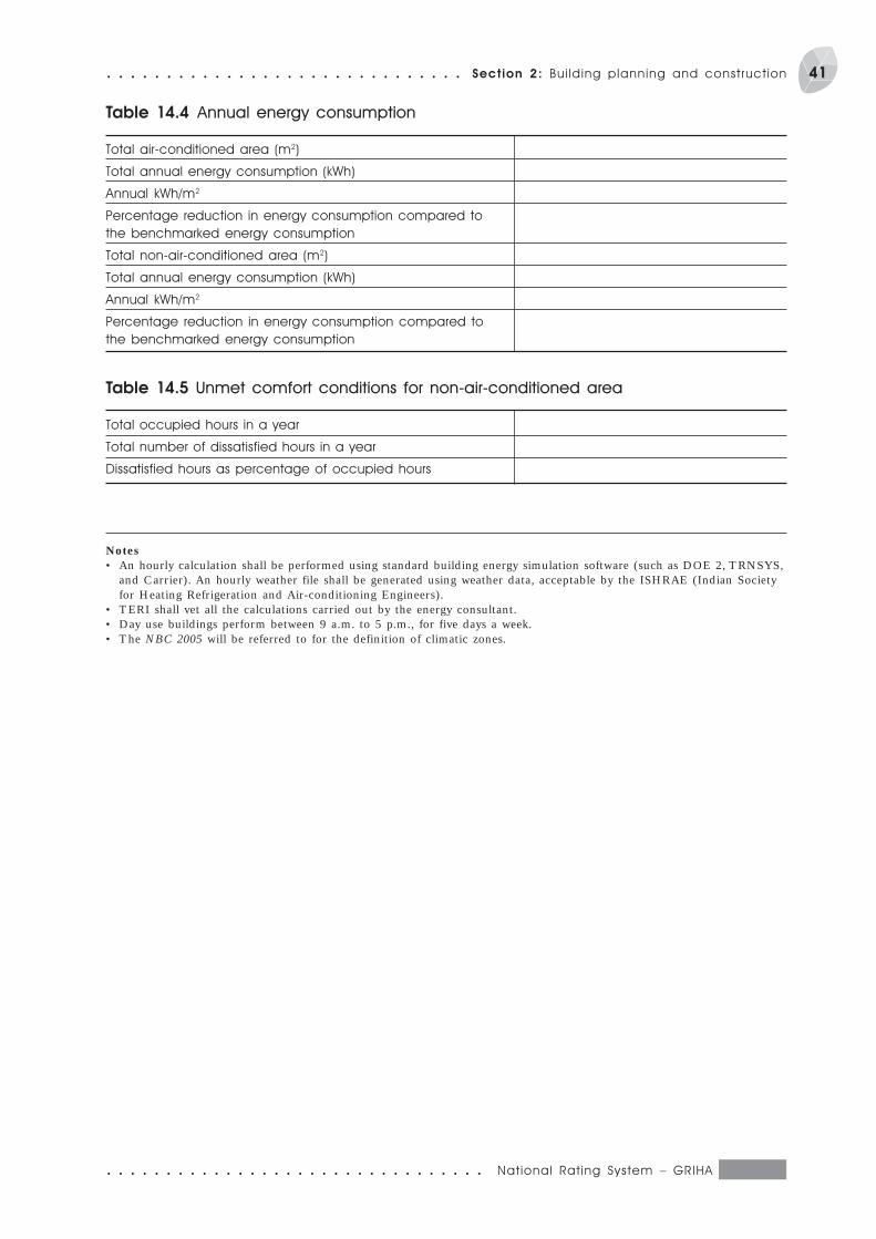
○ ○ ○ ○ ○ ○ ○ ○ ○ ○ ○ ○ ○ ○ ○ ○ ○ ○ ○ ○ ○ ○ ○ ○ ○ ○ ○ ○ ○ ○ ○ ○ National Rat ing System – GRIHA
41○ ○ ○ ○ ○ ○ ○ ○ ○ ○ ○ ○ ○ ○ ○ ○ ○ ○ ○ ○ ○ ○ ○ ○ ○ ○ ○ ○ ○ ○ Section 2: Bui lding planning and construct ion
Table 14.4 Annual energy consumption
Total air-conditioned area (m2)
Total annual energy consumption (kWh)
Annual kWh/m2
Percentage reduction in energy consumption compared to
the benchmarked energy consumption
Total non-air-conditioned area (m2)
Total annual energy consumption (kWh)
Annual kWh/m2
Percentage reduction in energy consumption compared to
the benchmarked energy consumption
Table 14.5 Unmet comfort conditions for non-air-conditioned area
Total occupied hours in a year
Total number of dissatisfied hours in a year
Dissatisfied hours as percentage of occupied hours
Notes• An hourly calculation shall be performed using standard building energy simulation software (such as DOE 2, TRNSYS,
and Carrier). An hourly weather file shall be generated using weather data, acceptable by the ISHRAE (Indian Societyfor Heating Refrigeration and Air-conditioning Engineers).
• TERI shall vet all the calculations carried out by the energy consultant.• Day use buildings perform between 9 a.m. to 5 p.m., for five days a week.• The NBC 2005 will be referred to for the definition of climatic zones.
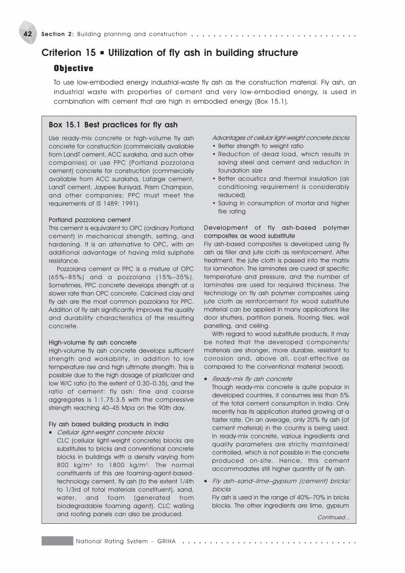
National Rat ing System – GRIHA ○ ○ ○ ○ ○ ○ ○ ○ ○ ○ ○ ○ ○ ○ ○ ○ ○ ○ ○ ○ ○ ○ ○ ○ ○ ○ ○ ○ ○ ○ ○ ○
42 Section 2: Bui lding planning and construct ion ○ ○ ○ ○ ○ ○ ○ ○ ○ ○ ○ ○ ○ ○ ○ ○ ○ ○ ○ ○ ○ ○ ○ ○ ○ ○ ○ ○ ○ ○
Criterion 15 P Utilization of fly ash in building structure
Objective
To use low-embodied energy industrial-waste fly ash as the construction material. Fly ash, an
industrial waste with properties of cement and very low-embodied energy, is used in
combination with cement that are high in embodied energy (Box 15.1).
Use ready-mix concrete or high-volume fly ash
concrete for construction (commercially available
from LandT cement, ACC suraksha, and such other
companies) or use PPC (Port land pozzolana
cement) concrete for construction (commercially
available from ACC suraksha, Lafarge cement,
LandT cement, Jaypee Buniyad, Prism Champion,
and other companies; PPC must meet the
requirements of IS 1489: 1991).
Portland pozzolona cement
This cement is equivalent to OPC (ordinary Portland
cement) in mechanical strength, setting, and
hardening. It is an alternative to OPC, with an
additional advantage of having mild sulphate
resistance.
Pozzolana cement or PPC is a mixture of OPC
(65%–85%) and a pozzolana (15%–35%).
Sometimes, PPC concrete develops strength at a
slower rate than OPC concrete. Calcined clay and
fly ash are the most common pozzolana for PPC.
Addition of fly ash significantly improves the quality
and durabil ity characterist ics of the result ing
concrete.
High-volume fly ash concrete
High-volume fly ash concrete develops sufficient
st rength and workabi l i ty, in addit ion to low
temperature rise and high ultimate strength. This is
possible due to the high dosage of plasticizer and
low W/C ratio (to the extent of 0.30–0.35), and the
rat io of cement: f ly ash: f ine and coarse
aggregates is 1:1.75:3.5 with the compressive
strength reaching 40–45 Mpa on the 90th day.
Fly ash based building products in India
P Cellular light-weight concrete blocks
CLC (cellular light-weight concrete) blocks are
substitutes to bricks and conventional concrete
blocks in buildings with a density varying from
800 kg/m3 to 1800 kg/m3. The normal
constituents of this are foaming-agent-based-
technology cement, fly ash (to the extent 1/4th
to 1/3rd of total materials constituent), sand,
water, and foam (generated from
biodegradable foaming agent). CLC walling
and roofing panels can also be produced.
Box 15.1 Best practices for fly ash
Advantages of cellular light-weight concrete blocks
· Better strength to weight ratio
· Reduction of dead load, which results in
saving steel and cement and reduction in
foundation size
· Better acoustics and thermal insulation (air
conditioning requirement is considerably
reduced)
· Saving in consumption of mortar and higher
fire rating
Development of f ly ash-based polymer
composites as wood substitute
Fly ash-based composites is developed using fly
ash as filler and jute cloth as reinforcement. After
treatment, the jute cloth is passed into the matrix
for lamination. The laminates are cured at specific
temperature and pressure, and the number of
laminates are used for required thickness. The
technology on fly ash polymer composites using
jute cloth as reinforcement for wood substitute
material can be applied in many applications like
door shutters, partition panels, flooring tiles, wall
panelling, and ceiling.
With regard to wood substitute products, it may
be noted that the developed components/
materials are stronger, more durable, resistant to
corrosion and, above al l , cost-effect ive as
compared to the conventional material (wood).
P Ready-mix fly ash concrete
Though ready-mix concrete is quite popular in
developed countries, it consumes less than 5%
of the total cement consumption in India. Only
recently has its application started growing at a
faster rate. On an average, only 20% fly ash (of
cement material) in the country is being used.
In ready-mix concrete, various ingredients and
quality parameters are str ictly maintained/
controlled, which is not possible in the concrete
produced on-s i te. Hence, this cement
accommodates still higher quantity of fly ash.
P Fly ash–sand–lime–gypsum (cement) bricks/
blocks
Fly ash is used in the range of 40%–70% in bricks
blocks. The other ingredients are lime, gypsum
Continued...
○ ○ ○ ○ ○ ○ ○ ○ ○ ○ ○ ○ ○ ○ ○ ○ ○ ○ ○ ○ ○ ○ ○ ○ ○ ○ ○ ○ ○ ○ ○ ○ National Rat ing System – GRIHA
43○ ○ ○ ○ ○ ○ ○ ○ ○ ○ ○ ○ ○ ○ ○ ○ ○ ○ ○ ○ ○ ○ ○ ○ ○ ○ ○ ○ ○ ○ Section 2: Bui lding planning and construct ion
Box 15.1 Continued...
(cement), sand, stone dust/chips, and others.
The minimum compressive strength (28 days) of
70 kg/cm2 can easily be achieved, and this can
go up to 250 kg/cm2 (in autoclaved type).
Advantage of these bricks over burnt clay bricks
· Lower requirement of mortar in construction
· Plastering over brick can be avoided
· Controlled dimensions, edges, and a smooth
and fine finish. The bricks can be in different
colours (using pigments)
· Cost-effect ive, energy-eff icient and
environment friendly (as it avoids the use of
fertile clay)
P Clay-fly ash bricks
The f ly ash content can be 20%–60%,
depending on the quality of clay. The process
of manufacturing is the same as for the burnt
clay bricks.
Advantages
· Fuel requirement is considerably reduced as
fly ash contains some percentage of unburnt
carbon
· Better thermal insulation
· Cost-effective and environment friendly
In i t iat ives taken by var ious government
departments in India
P Initiatives by the Ministry of Environment and
Forests, Government of India
The MoEF issued notification 8.0.763(E), dated
14 September 1999, containing Directive for
greater fly ash utilization, some of which are
listed below.
i. Within a radius of 100 km from coal- or TPP
lignite-based TPP (thermal power plants),
manufacturers of bricks/blocks/tiles should
use at least 25% of fly ash in their product.
ii. Every construction agency engaged in the
construction of buildings within a radius of
50–100 km of TPP had to use 100% fly ash-
based bricks/blocks in their construction
project by the end of August 2007.
Construction agencies, within 50 km radius of
TPP, had to use 100% fly ash-based bricks/
blocks by the end of August 2005. Any brick/
block containing more than 25% fly ash is
categorized as fly ash brick/block.
P Status of standardization in the country
• Several init iatives taken by the country’s
standardizat ion body (Bureau of Indian
Standards) regarding higher utilization of fly
ash are given below.
• Updating IS (Indian Standards) on ‘Portland
Pozzolana Cement – Specification Part 1 Fly
Ash based’ (IS 1489 (Part 1): 1991). In the
amended form, the fly ash constituent shall
not be less than 15% (from earlier 10%) and
not more than 35% (from earlier 25%) by
mass of PPC.
• Revision of the basic Indian Standard Design
Code for Plain and Reinforced Concrete (IS
456:2000). This revised code lays emphasis
on the use of PPC/fly ash in concrete in non-
conducive environmental conditions.
• Revision of the IS on Specification for fly ash
for use as pozzolana and admixture (IS 3812:
2003).
The standards have been updated keeping in
view the change in technologies, which led to the
generation of better quality of fly ashes and their
wider applications. In the revised standard, the
concept of improvement of fly ash properties
through beneficiation/segregation/processing has
also been introduced.
Quality and specifications
The fly ash used shall conform to specifications for
use of fly ash as pozzolana and admixture to
IS 3812: 2003. Moreover, percentage replacement
of cement with fly ash in concrete shall not exceed
the acceptable limits and exposure conditions,
conforming to IS 456: 2000.
· PPC (fly ash based) should conform to IS 1489
(part 1): 1991.
· Cert i f icate f rom an author ized st ructural
engineer that the structural integrity of the
construct ion conforms to the st ructural
standards, as prescribed in the IS Codes.
15.1 Commitment
To achieve the objective, the following criteriacan be applied to different components of thebuilding.
15.1.1 RC (reinforced concrete) (includingready-mix concrete) to make use of fly ash byusing PPC (Portland pozzolona cement)
containing fly ash. A minimum of 15%replacement of cement with fly ash in PPC (byweight of the cement used) in the overall RCfor meeting the equivalent strengthrequirements.
15.1.2 Use fly ash in building blocks for thewalls.
National Rat ing System – GRIHA ○ ○ ○ ○ ○ ○ ○ ○ ○ ○ ○ ○ ○ ○ ○ ○ ○ ○ ○ ○ ○ ○ ○ ○ ○ ○ ○ ○ ○ ○ ○ ○
44 Section 2: Bui lding planning and construct ion ○ ○ ○ ○ ○ ○ ○ ○ ○ ○ ○ ○ ○ ○ ○ ○ ○ ○ ○ ○ ○ ○ ○ ○ ○ ○ ○ ○ ○ ○
Use of fly ash-based bricks/blocks (such asFal-G stabilized, fly ash–sand lime bricks, loadbearing and non-load bearing fly ash-basedconcrete blocks, and fly ash-based light weightaerated concrete walling blocks) in both 100%load-bearing and non-load-bearing wallsystems, which utilize a minimum of 40% offly ash by weight of cement.
15.1.3 Use fly ash in plaster/masonrymortar by employing PPC.
Use plaster and/or masonry mortar, whichutilizes a minimum of 30% of fly ash in PPC,in 100% wall/ceiling finishes and wallconstruction, meeting the required structuralproperties.
15.2 Compliance
The following documents are to be submitted.15.2.1 Fly ash use in RC: Minimum 15%
replacement of cement with fly ash (by weightof cement used) in the total structural concrete.Provide supporting document from themanufacturer of cement specifying the fly ashcontent in PPC used in reinforced concrete.
15.2.2 Fly ash use in building blocks of load-bearing and non-load-bearing walls: Minimum40% replacement of cement with fly ash (byweight of cement used), for 100% load-bearingand non-load-bearing walls. Providesupporting document from the manufacturerof the pre-cast building blocks specifying the
fly ash content of the blocks used in an infillwall system.
15.2.3 Fly ash use in plaster and masonrymortar: Minimum 30% use of fly ash in placeof cement (by weight) in overall plaster andmortar requirements. Provide supportingdocument from the manufacturer of thecement/ready-mix concrete specifying the flyash content in the PPC used in plaster andmasonry mortar.
15.2.4 Certificate from the architectspecifying overall replacement of cement inthe RC and pre-cast building blocks plasterand masonry in the specified format (inprescribed certificate format).
15.3 Appraisal (maximum points – 6)
15.3.1 Minimum 15% replacement of Portlandcement with fly ash (by weight of cement used)in structural concrete, as per clause 15.2.1 — 1point (additional 1 point if more than 30%).
15.3.2 Minimum 40% replacement ofPortland cement with fly ash (by weight ofcement used), for 100% load-bearing and non-load-bearing walls, as per clause 15.2.2 —1 point (additional 1 point if more than 40%).
15.3.3 Minimum 30% replacement ofPortland cement with fly ash (by weight ofcement used) in plaster/masonry mortar, asper clause 15.2.3 — 1 point (additional 1 pointif more than 30%).
○ ○ ○ ○ ○ ○ ○ ○ ○ ○ ○ ○ ○ ○ ○ ○ ○ ○ ○ ○ ○ ○ ○ ○ ○ ○ ○ ○ ○ ○ ○ ○ National Rat ing System – GRIHA
45○ ○ ○ ○ ○ ○ ○ ○ ○ ○ ○ ○ ○ ○ ○ ○ ○ ○ ○ ○ ○ ○ ○ ○ ○ ○ ○ ○ ○ ○ Section 2: Bui lding planning and construct ion
Criterion 16 P Reduce volume, weight, and construction time byadopting efficient technologies (such as pre-cast systems)
Objective
Replace a part of energy-intensive materials with less energy-intensive materials and/or utilize
regionally available materials, which use low-energy/energy-efficient technologies. (Boxes 16.1
and 16.2).
Sustainably managed materials, when compared
with equivalent products for the same application,
have the character ist ics of natural resource
conservation – low-energy content, reduction in the
content of primary/high-energy materials, regional
availability, and low emission levels of pollutant –
in each stage of their life cycle. The amount of
materials used in the construction of buildings, for
either structural or non-structural applications,
represents a significant use of natural resources in
terms of extracted raw materials and embodied
energy.
The aim of this measure is to replace a part of
the energy-intensive materials with less energy-
intensive mater ials and/or ut i l ize regional ly
avai lable mater ials, which offers reduced
transportation, with the use of low-energy/energy-
Box 16.1 Energy-efficient technologies
efficient technologies (not based on the utilization
of fly ash). Examples of such structural or non-
structural appl ications (excluding wood) are
pre-cast technologies for roofing or flooring, pre-
cast infil l wall panels, composite ferrocement
system, and traditional mud walling techniques.
These techniques cause reduction/over-use in the
volume of concrete or steel used and, at the same
time, save on-site construction time. This credit
takes into consideration only those materials or
technologies which are not based on the utilization
of fly ash. The applicant, therefore, can accredit
either in the credit for utilization of fly ash or use of
low-energy technologies. However, i f the
accreditation overlaps on the aforesaid two credits,
points will be awarded to any one of them.
Stabilized compressed earth blocks are made up
of mud stabilized with 5% cement lime and other
mater ials, and compacted in block making
machines with no burning. A good material for
walls such as burnt bricks is economical, energy
saving, and simple to manufacture. The soil to be
used for the blocks should have the requisite
component of clay, silt, and sand. Soil-stabilized
hollow and interlocking blocks can provide better
thermal insulation.
Stabi l ized adobe is an improvement over
traditional adobe or hand-moulded and sun-dried
mud block in which mud is mixed with a small
proportion of cement, lime, broken or cut dry grass
(as reinforcing media to impart added strength
and lower the permeability). It is appropriate for dry
climates.
Pre-cast stone blocks are of larger size than normal
bricks. These are manufactured by using waste
stone pieces of various sizes with lean cement
concrete and enable a rationalized use of locally
Box 16.2 Best practices
available materials. This saves on cement, reduces
thickness of stonewalls, and eliminates the use of
plasters on internal/external surfaces. Use native or
quarried (stone where available within the delivery
radius <100–150 km), which has a very less
embodied energy content, negligible transport
energy costs, and needs only shaping. Lightweight
stone, which is made from cement and recycled
aggregates or furnace clinkers, can also be a
resourceful option.
Pre-cast concrete blocks are made to similar
dimension of stone blocks but without large size
stone pieces. These blocks use coarse and fine
graded aggregate with cement. They have
excellent properties comparable to other masonry
block.
Pre-cast hollow concrete blocks, manufactured
using lean cement concrete mixes and extruded
through block-making machines of egg laying or
static type, need lesser cement mortar and enable
speedy construct ion as compared to br ick
Continued...
National Rat ing System – GRIHA ○ ○ ○ ○ ○ ○ ○ ○ ○ ○ ○ ○ ○ ○ ○ ○ ○ ○ ○ ○ ○ ○ ○ ○ ○ ○ ○ ○ ○ ○ ○ ○
46 Section 2: Bui lding planning and construct ion ○ ○ ○ ○ ○ ○ ○ ○ ○ ○ ○ ○ ○ ○ ○ ○ ○ ○ ○ ○ ○ ○ ○ ○ ○ ○ ○ ○ ○ ○
16.1 Commitment
16.1.1 Structural application
Use of low-energy technologies/materials (notbased on the utilization of fly ash), such asroofing/flooring, columns, and load-bearingwalls, for structural applications. Suchtechnologies cause a minimum 5% (byabsolute volume) reduction in the use of high-energy materials (such as cement, concrete,and steel) when compared to equivalentproducts for the same application for a 100%structural system used in a building, thusmeeting the equivalent strength requirements.
Examples of low-energy products and technologiesused in structural applicationsPre-cast/pre-fabricated technologies such aspre-stressed slab, extruded structural clay joistand filler slab, hollow floor/roof slabs, pre-cast reinforced brick/tile panels, pre-castwaffle/cored units, pre-cast in situ thin-ribbedslabs, filler slabs or burned clay filler pots withRCC structure, micro-concrete roofing, pre-cast hollow plank roofing, funicular shells,zipbloc system, composite columns, reinforcedgrouted brick masonry, stone masonry, pre-cast stone blocks, pre-cast concrete blocks,pre-cast finished concrete blocks, light-weightconcrete blocks over dense concrete blocks,and rat trap masonry.
16.1.2 Non-structural application:
masonry/infill wall system
Use of low-energy technologies/materials (notbased on the utilization of fly ash) for non-structural applications. Such technologies causea minimum 5% by absolute volume reduction in
the use of high-energy materials, such as cement,concrete, and steel, when compared toequivalent products for the same application, for100% infill wall system used in a building,meeting the equivalent strength requirements.
Examples of low-energy product and technologiesin non-structural applicationsInfill wall system using traditional mudwalling system, stabilized adobe walling,compressed earth blocks, hollow, perforated/modular bricks, interlocking bricks, traditionalstone masonry, pre-cast non-load-bearingconcrete blocks, finished concrete blocks, lightweight concrete blocks over dense concreteblocks, pre-cast brick panels, compositeferrocement walling, interlocking concreteblocks, rat trap masonry, and so on.
16.2 Compliance
The following documents are to be submitted.16.2.1 Cut sheets, specification sheets and
bill of quantity demonstrating the percentagereduction in high-energy materials with theuse of low-energy technologies.
16.2.2 Document to demonstrate the use ofthe aforesaid technologies in the relevant floorplans, with clear dimensions and enlisting ofspecifications.
16.2.3 Narrative showing how the selectedtechnology has amounted to reduction in high-energy materials or regional availability whencompared with equivalent products for thesame application. On-site photographs andconstruction project management plan, whichwould clearly demonstrate the use/construction/specifications of low-energytechnologies.
Box 16.2 Continued...
masonry. The cavity in the blocks provide better
thermal insulation and does not need external/
internal plastering. These can be used as walling
block or roofing blocks along with inverted pre-cast
tee beams.
Rat-trap bond is an alternative brick-bonding
system for English and Flemish bond. It saves 25%
of the total number of bricks and 40% of mortar.
Composite ferrocement system is s imple to
construct and is made of ferrocement, that is, rich
mortar reinforced with chicken and welded wire
mesh. This system reduces the wall thickness and
allows larger carpet area. Pre-cast ferrocement
units in trough shape are integrated with RCC
columns. Ferrocement units serve as a permanent
skin unit and a diagonal strut between columns.
Inside cladding can be done with mud blocks or
any locally viable material.

○ ○ ○ ○ ○ ○ ○ ○ ○ ○ ○ ○ ○ ○ ○ ○ ○ ○ ○ ○ ○ ○ ○ ○ ○ ○ ○ ○ ○ ○ ○ ○ National Rat ing System – GRIHA
47○ ○ ○ ○ ○ ○ ○ ○ ○ ○ ○ ○ ○ ○ ○ ○ ○ ○ ○ ○ ○ ○ ○ ○ ○ ○ ○ ○ ○ ○ Section 2: Bui lding planning and construct ion
16.3 Appraisal (maximum points – 4)
16.3.1 Structural application
P Use of low-energy technologies in structuralapplication clearly demonstrating aminimum 5% reduction in high energymaterials such as cement, concrete, steel,sand, and bricks by absolute volume whencompared with equivalent products for thesame application, for 100% structural systemused in a building, meeting the equivalentstrength requirements, as per all complianceclauses (2 points).
16.3.2 Non-structural application
P Use of low-energy technologies/materials(not based on the utilization of industrialwaste), which are used for non-structuralapplications such as infill wall system andcause a minimum 5% reduction in the useof high-energy materials, such as cement,concrete, and steel, by absolute volumewhen compared with equivalent productsfor the same application, for 100% infillwall system used in a building, meeting theequivalent strength requirements, as per allcompliance clauses (2 points).
National Rat ing System – GRIHA ○ ○ ○ ○ ○ ○ ○ ○ ○ ○ ○ ○ ○ ○ ○ ○ ○ ○ ○ ○ ○ ○ ○ ○ ○ ○ ○ ○ ○ ○ ○ ○
48 Section 2: Bui lding planning and construct ion ○ ○ ○ ○ ○ ○ ○ ○ ○ ○ ○ ○ ○ ○ ○ ○ ○ ○ ○ ○ ○ ○ ○ ○ ○ ○ ○ ○ ○ ○
Criterion 17 P Use low-energy material in interiors
Objective
To use low-energy/recycled materials/finishes/products in the interiors, which minimize the use
of wood as a natural resource. To use low-energy materials and products, such as composite
wood products/renewable materials/reused wood/low embodied energy products/products
which utilize industrial waste/recycled products.
The various interior finishes used in the sub-system of the building or the interior, which serve
the aim of the credit, have been divided into the following three major categories. If any interior
finish, acclaimed for credit, falls beyond this classification, the applicant has to clearly confirm
the criteria that meet the requirements of the credit.
P Sub-assembly/internal partitions/interior wood finishes/panelling/false ceiling/in-built furniture/
cabinetry
P Flooring
P Doors/windows and frames
· Composite wood products such as hardboards,
blockboards, lumber-core plywood, veneered
panels, particle boards, medium/low density
fibreboards made from recycled wood scrap
from sawmill dusts or furniture industry bonded
with glue or resin under heat and pressure.
· Rapidly renewable materials/products, which
are made from small diameter trees and fast
growing low utilized species harvested within a
10 year cycle or shorter such as bamboo,
rubber, eucrasia, eucalyptus, poplar, jute/cotton
stalks. The products include, among others,
engineered products, bamboo ply boards,
rubber, jute stalk boards.
· Products, which utilize industrial waste such as
wood waste, agricultural waste and natural
fibres like sisal, coir, and glass fibre in inorganic
matr ices l ike gypsum, cement, and other
binders such as fibrous gypsum plaster boards.
· Salvaged timber and reused wood products
such as antique furniture.
· Low embodied energy products, which use
recycled materials like glass, crushed stone, and
other waste, such as terrazzo, or which are
resource efficient f inishes such as f inished
concrete flooring, ceiling tiles, and ceramic
tiles.
Box 17.1 Examples of low energy materials for interiors
17.1 Commitment
A minimum of 70% of the total quantity of allinterior finishes and products used in each ofthe categories mentioned above should below-energy finishes/materials/products,which minimize wood as a natural resource orutilize industrial waste by using products inany category as listed in Box 17.1.
17.2 Compliance
The following documents are to be submitted.17.2.1 Cut sheets, specification sheets,
commercial brochures or certificate from themanufacturer of the low energy finishes orproducts used in each category.
17.2.2 For each category, clearly demonstrateand differentiate the use of the aforesaidfinishes/products in the relevant interior
layouts/plans in a CAD drawing, either byshading, rendering or highlighting with cleardimension and enlisting specifications.
17.2.3 The bill of quantity for each of thecategory, as applicable to the applicant, clearlydemonstrating that minimum 70% of the totalquantity of all interior finishes and productsare low energy.
17.2.4 A narrative and photographsshowing how the selected low-energy finishesor products have minimized wood as naturalresource or utilized low energy material andproducts, when compared with equivalentproducts for the same application.
17.2.5 Certificate from architect/interiordesigner for use of low-energy material/product in various categories meeting requiredcriteria as described in the Commitment.

○ ○ ○ ○ ○ ○ ○ ○ ○ ○ ○ ○ ○ ○ ○ ○ ○ ○ ○ ○ ○ ○ ○ ○ ○ ○ ○ ○ ○ ○ ○ ○ National Rat ing System – GRIHA
49○ ○ ○ ○ ○ ○ ○ ○ ○ ○ ○ ○ ○ ○ ○ ○ ○ ○ ○ ○ ○ ○ ○ ○ ○ ○ ○ ○ ○ ○ Section 2: Bui lding planning and construct ion
17.3 Appraisal (maximum points – 4)
A minimum of 70% of the total quantity (grossarea) of all interior finishes and products usedfor each of the category, as applicable, to below- energy finishes, for each of the followingcategory.
17.3.1 Sub-assembly/internal partitions/panelling/false ceiling/in-built furniture(2 points), as per clauses 17.2.1–17.2.5.
17.3.2 Flooring (1 point), as per clauses17.2.1–17.2.5.
17.3.3 Doors/windows and frames(1 point), as per clauses 17.2.1–17.2.5.
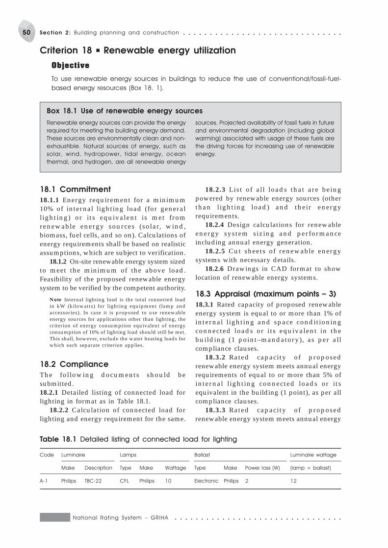
National Rat ing System – GRIHA ○ ○ ○ ○ ○ ○ ○ ○ ○ ○ ○ ○ ○ ○ ○ ○ ○ ○ ○ ○ ○ ○ ○ ○ ○ ○ ○ ○ ○ ○ ○ ○
50 Section 2: Bui lding planning and construct ion ○ ○ ○ ○ ○ ○ ○ ○ ○ ○ ○ ○ ○ ○ ○ ○ ○ ○ ○ ○ ○ ○ ○ ○ ○ ○ ○ ○ ○ ○
Criterion 18 P Renewable energy utilization
Objective
To use renewable energy sources in buildings to reduce the use of conventional/fossil-fuel-
based energy resources (Box 18. 1).
Renewable energy sources can provide the energy
required for meeting the building energy demand.
These sources are environmentally clean and non-
exhaustible. Natural sources of energy, such as
solar, wind, hydropower, t idal energy, ocean
thermal, and hydrogen, are all renewable energy
Box 18.1 Use of renewable energy sources
sources. Projected availability of fossil fuels in future
and environmental degradation (including global
warming) associated with usage of these fuels are
the driving forces for increasing use of renewable
energy.
18.1 Commitment
18.1.1 Energy requirement for a minimum10% of internal lighting load (for generallighting) or its equivalent is met fromrenewable energy sources (solar, wind,biomass, fuel cells, and so on). Calculations ofenergy requirements shall be based on realisticassumptions, which are subject to verification.
18.1.2 On-site renewable energy system sizedto meet the minimum of the above load.Feasibility of the proposed renewable energysystem to be verified by the competent authority.
Note Internal lighting load is the total connected loadin kW (kilowatts) for lighting equipment (lamp andaccessories). In case it is proposed to use renewableenergy sources for applications other than lighting, thecriterion of energy consumption equivalent of energyconsumption of 10% of lighting load should still be met.This shall, however, exclude the water heating loads forwhich each separate criterion applies.
18.2 Compliance
The following documents should besubmitted.18.2.1 Detailed listing of connected load forlighting in format as in Table 18.1.
18.2.2 Calculation of connected load forlighting and energy requirement for the same.
18.2.3 List of all loads that are beingpowered by renewable energy sources (otherthan lighting load) and their energyrequirements.
18.2.4 Design calculations for renewableenergy system sizing and performanceincluding annual energy generation.
18.2.5 Cut sheets of renewable energysystems with necessary details.
18.2.6 Drawings in CAD format to showlocation of renewable energy systems.
18.3 Appraisal (maximum points – 3)
18.3.1 Rated capacity of proposed renewableenergy system is equal to or more than 1% ofinternal lighting and space conditioningconnected loads or its equivalent in thebuilding (1 point–mandatory), as per allcompliance clauses.
18.3.2 Rated capacity of proposedrenewable energy system meets annual energyrequirements of equal to or more than 5% ofinternal lighting connected loads or itsequivalent in the building (1 point), as per allcompliance clauses.
18.3.3 Rated capacity of proposedrenewable energy system meets annual energy
Table 18.1 Detailed listing of connected load for lighting
Code Luminaire Lamps Ballast Luminaire wattage
Make Description Type Make Wattage Type Make Power loss (W) (lamp + ballast)
A-1 Philips TBC-22 CFL Philips 10 Electronic Philips 2 12

○ ○ ○ ○ ○ ○ ○ ○ ○ ○ ○ ○ ○ ○ ○ ○ ○ ○ ○ ○ ○ ○ ○ ○ ○ ○ ○ ○ ○ ○ ○ ○ National Rat ing System – GRIHA
51○ ○ ○ ○ ○ ○ ○ ○ ○ ○ ○ ○ ○ ○ ○ ○ ○ ○ ○ ○ ○ ○ ○ ○ ○ ○ ○ ○ ○ ○ Section 2: Bui lding planning and construct ion
requirements of equal to or more than 10% ofinternal lighting connected loads or itsequivalent in the building (1 point), as per allcompliance clauses.
18.3.4 Rated capacity of proposedrenewable energy system meets annual energyrequirements of equal to or more than 20% ofinternal lighting connected loads or itsequivalent in the building, as per allcompliance clauses (2 points).
18.3.5 Rated capacity of proposedrenewable energy system meets annual energyrequirements of equal to or more than 30% ofinternal lighting connected loads or itsequivalent in the building, as per allcompliance clauses (3 points).
Note Lighting design shall be based on minimumrequirements as per NBC 2005 (BIS 2005d) (criterion
12.1.5).
National Rat ing System – GRIHA ○ ○ ○ ○ ○ ○ ○ ○ ○ ○ ○ ○ ○ ○ ○ ○ ○ ○ ○ ○ ○ ○ ○ ○ ○ ○ ○ ○ ○ ○ ○ ○
52 Section 2: Bui lding planning and construct ion ○ ○ ○ ○ ○ ○ ○ ○ ○ ○ ○ ○ ○ ○ ○ ○ ○ ○ ○ ○ ○ ○ ○ ○ ○ ○ ○ ○ ○ ○
Criterion 19 P Renewable-energy-based hot water system
Objective
To use renewable energy sources to meet the hot-water requirement.
Guidelines for sizing, installation, and use of solar
collectors
P Solar collectors should face south for maximum
solar radiation collection.
P The solar collector tilt should be equal to the
latitude of the place for maximum annual
energy collection.
P The solar collector tilt should be equal to latitude
+ 150, gives maximum energy collection in
winter.
P The solar collector tilt should be equal to latitude
-150, gives maximum energy collection in
summer.
P Always check the load carrying capacity of the
roof before placing the solar collector. Typically,
each solar collector of 2 m2 area weighs 50 kg.
The solar tank, when filled with water, weighs
1.2–1.4 kg per l i t re capacity of tank. (For
example, 100 litre capacity tank weighs 120 kg)
P Ensure proper anchoring of the system duly
considering wind conditions.
P Solar col lectors and tank must be easi ly
accessible for cleaning and maintenance.
P A typical solar collector needs 1.3–1.5 times the
collector area for installation. For example, a
single collector system of 100-litre capacity,
having 2 m2 area, requires an area of 3 m2 for
installation.
Guidelines for solar collector selection and use
P Check hardness of water to be used in solar
system/collector?. Solar collectors have small
diameter pipes, which get chocked due to
deposition of salt from hard water. In case of hard
water, either water softener or heat-exchanger-
type solar water heater should be used.
P It is a good practice to consider solar collector
location and optimize the associated hot/cold
water piping layout during the building design
stage to reduce the cost and heat losses due
to longer piping.
P Always use good quality and long lasting pipes
and insulation for trouble-free working.
P It’s important to check operating pressure of
supply of cold water l ine, especially when
pressurized water is circulated. Most solar
systems available in India are not designed for
pressurized water supply.
P Ensure continuous supply of water to the solar
system for efficient and trouble-free operations.
P When not in use, during long periods always
cover the solar collectors with non-transparent
covers (such as an old bed sheet or jute cloth)/
to avoid overheating of solar system).
P It is a good practice to use the entire hot water
at a time.
P Avoid using back up heater. Do not keep back-
up heater switched on.
P Set the thermostat of back-up heater at
55–60 °C.
P Use proper vent or vacuum release valve and
pressure relief valve for safe operation of solar
system.
P Human body can tolerate temperature up to
45 °C. Human skin burns at water temperature
above 55 °C. Storage water heater temperature
can be set at 55 + 5 °C.
Guidelines for system sizing
P Typically, a solar hot water system is sized to
meet one day’s requirement of hot water during
winter. Typical hot water consumptions for
various activities are given below. These can be
used as guidelines for calculating total hot water
requirement. (The consumption figures may vary
depending on l i fe style, age, habits, and
weather conditions.)
P For bathing using bucket water = 15 litre per
person per day (one bucket).
P For shower bath = 25 litre per person per day.
P For bathtub = 35–50 litre per person per day.
P For cooking = 5 litre per person per day.
P For washing clothes = 10 litre per person per day.
P For washing utensils and other purposes = 5 litre
per person per meal.
P For making tea/coffee = 150 ml per person per cup
Box 19.1 Guidelines
19.1 Commitment
19.1.1 Ensure that a minimum 50% of theannual energy requirement for heating water(for applications such as hot water for all
needs, like for canteen, washing, and bathrooms/toilets, except for space heating) issupplied from renewable energy sources.
○ ○ ○ ○ ○ ○ ○ ○ ○ ○ ○ ○ ○ ○ ○ ○ ○ ○ ○ ○ ○ ○ ○ ○ ○ ○ ○ ○ ○ ○ ○ ○ National Rat ing System – GRIHA
53○ ○ ○ ○ ○ ○ ○ ○ ○ ○ ○ ○ ○ ○ ○ ○ ○ ○ ○ ○ ○ ○ ○ ○ ○ ○ ○ ○ ○ ○ Section 2: Bui lding planning and construct ion
19.2 Compliance
The following documents are to be submitted.19.2.1 Detailed calculations of hot water
requirements.19.2.2 Detailed calculations on energy
required for heating water for all needs exceptfor space heating (in kWh or litres of fossilfuel).
19.2.3 Detailed design calculations forrenewable energy system sizing andperformance including annual energygeneration.
19.2.4 Layout of the proposed renewableenergy system.
19.2.5 Test reports from approved testcentre for system performance and efficiency.
19.3 Appraisal (maximum points – 3)
19.3.1 Annual energy saved by proposedrenewable energy system is 20% to 50% ofannual energy required for water heating tomeet the hot water requirements of theoccupants in the building, as per allcompliance clauses (1 point).
19.3.2 Annual energy saved by proposedrenewable energy system is 50% to 70% ofannual energy required for water heating tomeet the hot water requirement of theoccupants in the building, as per allcompliance clauses (2 points).
19.3.3 Annual energy saved by proposedrenewable energy system is more than 70% ofannual energy required for water heating tomeet the hot water requirements of theoccupants in the building, as per allcompliance clauses (3 points).
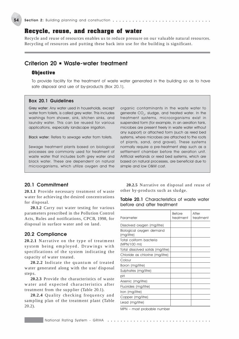
National Rat ing System – GRIHA ○ ○ ○ ○ ○ ○ ○ ○ ○ ○ ○ ○ ○ ○ ○ ○ ○ ○ ○ ○ ○ ○ ○ ○ ○ ○ ○ ○ ○ ○ ○ ○
54 Section 2: Bui lding planning and construct ion ○ ○ ○ ○ ○ ○ ○ ○ ○ ○ ○ ○ ○ ○ ○ ○ ○ ○ ○ ○ ○ ○ ○ ○ ○ ○ ○ ○ ○ ○
Recycle, reuse, and recharge of waterRecycle and reuse of resources enables us to reduce pressure on our valuable natural resources.Recycling of resources and putting these back into use for the building is significant.
Criterion 20 P Waste-water treatment
Objective
To provide facility for the treatment of waste water generated in the building so as to have
safe disposal and use of by-products (Box 20.1).
Grey water: Any water used in households, except
water from toilets, is called grey water. This includes
washings from shower, sink, kitchen sinks, and
laundry water. This can be reused for various
applications, especially landscape irrigation.
Black water: Refers to sewage water from toilets.
Sewage treatment plants based on biological
processes are commonly used for treatment of
waste water that includes both grey water and
black water. These are dependent on natural
microorganisms, which util ize oxygen and the
organic contaminants in the waste water to
generate CO2, sludge, and treated water. In the
treatment systems, microorganisms exist in
suspended form (for example, in an aeration tank,
microbes are present freely in waste water without
any support) or attached form (such as reed bed
systems, where microbes are attached to the roots
of plants, sand, and gravel). These systems
normally require a pre-treatment step such as a
settlement chamber before the aeration unit.
Artificial wetlands or reed bed systems, which are
based on natural processes, are beneficial due to
simple and low O&M cost.
Box 20.1 Guidelines
20.1 Commitment
20.1.1 Provide necessary treatment of wastewater for achieving the desired concentrationsfor disposal.
20.1.2 Carry out water testing for variousparameters prescribed in the Pollution ControlActs, Rules and notifications, CPCB, 1998, fordisposal in surface water and on land.
20.2 Compliance
20.2.1 Narrative on the type of treatmentsystem being employed. Drawings withspecifications of the system indicating thecapacity of water treated.
20.2.2 Indicate the quantum of treatedwater generated along with the use/disposalsteps.
20.2.3 Provide the characteristics of wastewater and expected characteristics aftertreatment from the supplier (Table 20.1).
20.2.4 Quality checking frequency andsampling plan of the treatment plant (Table20.2).
20.2.5 Narrative on disposal and reuse ofother by-products such as sludge.
Table 20.1 Characteristics of waste water
before and after treatment
Before After
Parameter treatment treatment
Dissolved oxygen (mg/litre)
Biological oxygen demand
(mg/litre)
Total coliform bacteria
(MPN/100 ml)
Total dissolved solids (mg/litre)
Chloride as chlorine (mg/litre)
Colour
Boron (mg/litre)
Sulphates (mg/litre)
pH
Arsenic (mg/litre)
Fluorides (mg/litre)
Iron (mg/litre)
Copper (mg/litre)
Lead (mg/litre)
MPN – most probable number
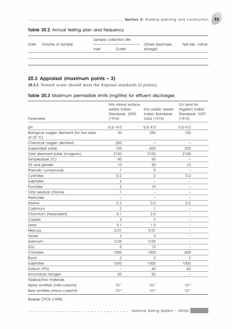
○ ○ ○ ○ ○ ○ ○ ○ ○ ○ ○ ○ ○ ○ ○ ○ ○ ○ ○ ○ ○ ○ ○ ○ ○ ○ ○ ○ ○ ○ ○ ○ National Rat ing System – GRIHA
55○ ○ ○ ○ ○ ○ ○ ○ ○ ○ ○ ○ ○ ○ ○ ○ ○ ○ ○ ○ ○ ○ ○ ○ ○ ○ ○ ○ ○ ○ Section 2: Bui lding planning and construct ion
20.3 Appraisal (maximum points – 2)
20.3.1 Treated water should meet the disposal standards (2 points).
Table 20.2 Annual testing plan and frequency
Sample collection site
Date Volume of sample Others (example, Test lab. name
Inlet Outlet storage)
Table 20.3 Maximum permissible limits (mg/litre) for effluent discharges
Into inland surface On land for
waters Indian Into public sewers irrigation Indian
Standards: 2490 Indian Standards: Standards: 3307
Parameter (1974) 3306 (1974) (1974)
pH 5.5.–9.0 5.5–9.0 5.5–9.0
Biological oxygen demand (for five days 30 350 100
at 20 oC)
Chemical oxygen demand 250 – –
Suspended solids 100 600 200
Total dissolved solids (inorganic) 2100 2100 2100
Temperature (oC) 40 45 –
Oil and grease 10 20 10
Phenolic compounds 1 5 –
Cyanides 0.2 2 0.2
Sulphides 2 – –
Fluorides 2 15 –
Total residual chlorine 1 – –
Pesticides – – –
Arsenic 0.2 0.2 0.2
Cadmium 2 1 –
Chromium (hexavalent) 0.1 2.0 –
Copper 3 3 –
Lead 0.1 1.0 –
Mercury 0.01 0.01 –
Nickel 3 3 –
Selenium 0.05 0.05 –
Zinc 5 15 –
Chlorides 1000 1000 600
Boron 2 2 2
Sulphates 1000 1000 1000
Sodium (9%) – 60 60
Amoniacal nitrogen 50 50 –
Radioactive materials
Alpha emitters (milli-curie/ml) 10–7 10–7 10–8
Beta emitters (micro-curie/ml) 10–6 10–6 10–7
Source CPCB (1998)
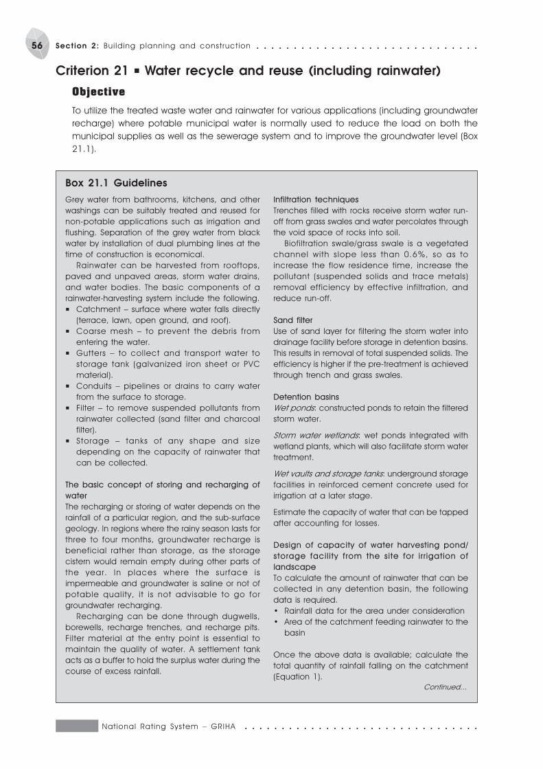
National Rat ing System – GRIHA ○ ○ ○ ○ ○ ○ ○ ○ ○ ○ ○ ○ ○ ○ ○ ○ ○ ○ ○ ○ ○ ○ ○ ○ ○ ○ ○ ○ ○ ○ ○ ○
56 Section 2: Bui lding planning and construct ion ○ ○ ○ ○ ○ ○ ○ ○ ○ ○ ○ ○ ○ ○ ○ ○ ○ ○ ○ ○ ○ ○ ○ ○ ○ ○ ○ ○ ○ ○
Criterion 21 P Water recycle and reuse (including rainwater)
Objective
To utilize the treated waste water and rainwater for various applications (including groundwater
recharge) where potable municipal water is normally used to reduce the load on both the
municipal supplies as well as the sewerage system and to improve the groundwater level (Box
21.1).
Grey water from bathrooms, kitchens, and other
washings can be suitably treated and reused for
non-potable applications such as irrigation and
flushing. Separation of the grey water from black
water by installation of dual plumbing lines at the
time of construction is economical.
Rainwater can be harvested from rooftops,
paved and unpaved areas, storm water drains,
and water bodies. The basic components of a
rainwater-harvesting system include the following.
P Catchment – surface where water falls directly
(terrace, lawn, open ground, and roof).
P Coarse mesh – to prevent the debris from
entering the water.
P Gutters – to collect and transport water to
storage tank (galvanized iron sheet or PVC
material).
P Conduits – pipelines or drains to carry water
from the surface to storage.
P Filter – to remove suspended pollutants from
rainwater collected (sand filter and charcoal
filter).
P Storage – tanks of any shape and s ize
depending on the capacity of rainwater that
can be collected.
The basic concept of storing and recharging of
water
The recharging or storing of water depends on the
rainfall of a particular region, and the sub-surface
geology. In regions where the rainy season lasts for
three to four months, groundwater recharge is
beneficial rather than storage, as the storage
cistern would remain empty during other parts of
the year. In places where the surface is
impermeable and groundwater is saline or not of
potable quality, i t is not advisable to go for
groundwater recharging.
Recharging can be done through dugwells,
borewells, recharge trenches, and recharge pits.
Filter material at the entry point is essential to
maintain the quality of water. A settlement tank
acts as a buffer to hold the surplus water during the
course of excess rainfall.
Infiltration techniques
Trenches filled with rocks receive storm water run-
off from grass swales and water percolates through
the void space of rocks into soil.
Biofiltration swale/grass swale is a vegetated
channel with s lope less than 0.6%, so as to
increase the flow residence time, increase the
pollutant (suspended solids and trace metals)
removal efficiency by effective infiltration, and
reduce run-off.
Sand filter
Use of sand layer for filtering the storm water into
drainage facility before storage in detention basins.
This results in removal of total suspended solids. The
efficiency is higher if the pre-treatment is achieved
through trench and grass swales.
Detention basins
Wet ponds: constructed ponds to retain the filtered
storm water.
Storm water wetlands: wet ponds integrated with
wetland plants, which will also facilitate storm water
treatment.
Wet vaults and storage tanks: underground storage
facilities in reinforced cement concrete used for
irrigation at a later stage.
Estimate the capacity of water that can be tapped
after accounting for losses.
Design of capacity of water harvesting pond/
storage facil i ty from the site for i r r igation of
landscape
To calculate the amount of rainwater that can be
collected in any detention basin, the following
data is required.
· Rainfall data for the area under consideration
· Area of the catchment feeding rainwater to the
basin
Once the above data is available; calculate the
total quantity of rainfall falling on the catchment
(Equation 1).
Box 21.1 Guidelines
Continued...
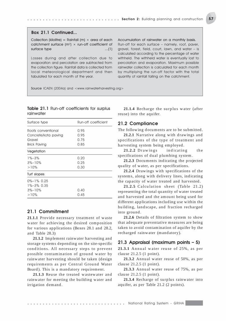
○ ○ ○ ○ ○ ○ ○ ○ ○ ○ ○ ○ ○ ○ ○ ○ ○ ○ ○ ○ ○ ○ ○ ○ ○ ○ ○ ○ ○ ○ ○ ○ National Rat ing System – GRIHA
57○ ○ ○ ○ ○ ○ ○ ○ ○ ○ ○ ○ ○ ○ ○ ○ ○ ○ ○ ○ ○ ○ ○ ○ ○ ○ ○ ○ ○ ○ Section 2: Bui lding planning and construct ion
21.1 Commitment
21.1.1 Provide necessary treatment of wastewater for achieving the desired compositionfor various applications (Boxes 28.1 and 28.2,and Table 28.3)
21.1.2 Implement rainwater harvesting andstorage systems depending on the site-specificconditions. All necessary steps to preventpossible contamination of ground water byrainwater harvesting should be taken (designrequirements as per Central Ground WaterBoard). This is a mandatory requirement.
21.1.3 Reuse the treated wastewater andrainwater for meeting the building water andirrigation demand.
Box 21.1 Continued...
Collection (kilolitre) = Rainfall (m) × area of each
catchment surface (m2) × run-off coefficient of
surface type …(1)
Losses dur ing and after col lect ion due to
evaporation and percolation are subtracted from
the collection figure. Rainfall data is collected from
local meteorological department and then
tabulated for each month of the year.
Accumulation of rainwater on a monthly basis.
Run-off for each surface – namely, roof, paver,
gravel, forest, field, court, lawn, and water – is
calculated according to the percentage of water
withheld. The withheld water is eventually lost to
percolation and evaporation. Maximum possible
rainwater collection is calculated for each month
by multiplying the run-off factor with the total
quantity of rainfall falling on the catchment.
Source ICAEN (2004a) and <www.rainwaterharvesting.org>
Table 21.1 Run-off coefficients for surplus
rainwater
Surface type Run-off coefficient
Roofs conventional 0.95
Concrete/kota paving 0.95
Gravel 0.75
Brick Paving 0.85
Vegetation
1%–3% 0.20
3%–10% 0.25
>10% 0.30
Turf slopes
0%–1% 0.25
1%–3% 0.35
3%–10% 0.40
>10% 0.45
21.1.4 Recharge the surplus water (afterreuse) into the aquifer.
21.2 Compliance
The following documents are to be submitted.21.2.1 Narrative along with drawings and
specifications of the type of treatment andharvesting system being employed.
21.2.2 Drawings indicating thespecifications of dual plumbing system.
21.2.3 Documents indicating the projectedquality of water, as per specifications.
21.2.4 Drawings with specifications of thesystems, along with delivery lines, indicatingthe capacity of water treated and harvested.
21.2.5 Calculation sheet (Table 21.2)representing the total quantity of water treatedand harvested and the amount being used fordifferent applications including use within thebuilding, landscape, and fraction rechargedinto ground.
21.2.6 Details of filtration system to showthat adequate preventative measures are beingtaken to avoid contamination of aquifer by therecharged rainwater (mandatory).
21.3 Appraisal (maximum points – 5)
21.3.1 Annual water reuse of 25%, as perclause 21.2.5 (1 point).
21.3.2 Annual water reuse of 50%, as perclause 21.2.5 (1 point).
21.3.3 Annual water reuse of 75%, as perclause 21.2.5 (1 point).
21.3.4 Recharge of surplus rainwater intoaquifer, as per Table 21.2 (2 points).

National Rat ing System – GRIHA ○ ○ ○ ○ ○ ○ ○ ○ ○ ○ ○ ○ ○ ○ ○ ○ ○ ○ ○ ○ ○ ○ ○ ○ ○ ○ ○ ○ ○ ○ ○ ○
58 Section 2: Bui lding planning and construct ion ○ ○ ○ ○ ○ ○ ○ ○ ○ ○ ○ ○ ○ ○ ○ ○ ○ ○ ○ ○ ○ ○ ○ ○ ○ ○ ○ ○ ○ ○
Table 21.2 Water reuse datasheet
Water
Quantity Quantity requirement Landscape Water Water
of water of water of the water reused for reused for Water Water
treated harvested building demand building landscape recharged Water recharge
Month (kilolitres) (kilolitres) (kilolitres) (kilolitres) (kilolitres) (kilolitres) (kilolitres) reuse (%) (%)
A B C D x y z (x + y)/ ( (z/B) * 100
C + D) ×
100
January
February
March
April
May
June
July
August
September
October
November
December
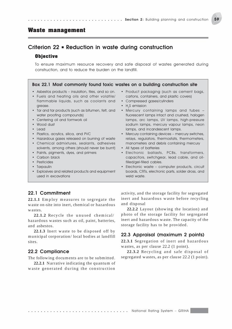
○ ○ ○ ○ ○ ○ ○ ○ ○ ○ ○ ○ ○ ○ ○ ○ ○ ○ ○ ○ ○ ○ ○ ○ ○ ○ ○ ○ ○ ○ ○ ○ National Rat ing System – GRIHA
59○ ○ ○ ○ ○ ○ ○ ○ ○ ○ ○ ○ ○ ○ ○ ○ ○ ○ ○ ○ ○ ○ ○ ○ ○ ○ ○ ○ ○ ○ Section 2: Bui lding planning and construct ion
Waste management
Criterion 22 P Reduction in waste during construction
Objective
To ensure maximum resource recovery and safe disposal of wastes generated during
construction, and to reduce the burden on the landfill.
· Asbestos products – insulation, tiles, and so on.
· Fuels and heating oi ls and other volat i le/
f lammable l iquids, such as coolants and
grease.
· Tar and tar products (such as bitumen, felt, and
water proofing compounds)
· Centering oil and formwork oil
· Wood dust
· Lead
· Plastics, acrylics, silica, and PVC
· Hazardous gases released on burning of waste
· Chemical admixtures, sealants, adhesives
solvents, among others (should never be burnt)
· Paints, pigments, dyes, and primers
· Carbon black
· Pesticides
· Tarpaulin
· Explosives and related products and equipment
used in excavations
· Product packaging (such as cement bags,
cartons, containers, and plastic covers)
· Compressed gases/cylinders
· H2S emission
· Mercury containing lamps and tubes –
fluorescent lamps intact and crushed, halogen
lamps, arc lamps, UV lamps, high-pressure
sodium lamps, mercury vapour lamps, neon
lamps, and incandescent lamps.
· Mercury containing devices – mercury switches,
relays, regulators, thermostats, thermometers,
manometers and debris containing mercury
· All types of batteries
· Electronic bal lasts, PCBs, t ransformers,
capacitors, switchgear, lead cable, and oil-
filled/gel-filled cables.
· Electronic waste – computer products, circuit
boards, CRTs, electronic parts, solder dross, and
weld waste.
Box 22.1 Most commonly found toxic wastes on a building construction site
22.1 Commitment
22.1.1 Employ measures to segregate thewaste on-site into inert, chemical or hazardouswastes.
22.1.2 Recycle the unused chemical/hazardous wastes such as oil, paint, batteries,and asbestos.
22.1.3 Inert waste to be disposed off bymunicipal corporation/local bodies at landfillsites.
22.2 Compliance
The following documents are to be submitted.22.2.1 Narrative indicating the quantum of
waste generated during the construction
activity, and the storage facility for segregatedinert and hazardous waste before recyclingand disposal
22.2.2 Layout (showing the location) andphoto of the storage facility for segregatedinert and hazardous waste. The capacity of thestorage facility has to be provided.
22.3 Appraisal (maximum 2 points)
22.3.1 Segregation of inert and hazardouswastes, as per clause 22.2 (1 point).
22.3.2 Recycling and safe disposal ofsegregated wastes, as per clause 22.2 (1 point).
National Rat ing System – GRIHA ○ ○ ○ ○ ○ ○ ○ ○ ○ ○ ○ ○ ○ ○ ○ ○ ○ ○ ○ ○ ○ ○ ○ ○ ○ ○ ○ ○ ○ ○ ○ ○
60 Section 2: Bui lding planning and construct ion ○ ○ ○ ○ ○ ○ ○ ○ ○ ○ ○ ○ ○ ○ ○ ○ ○ ○ ○ ○ ○ ○ ○ ○ ○ ○ ○ ○ ○ ○
Criterion 23 P Efficient waste segregation
Objective
To promote the segregation of waste for efficient resource recovery.
23.1 Commitment
23.1.1 Use different coloured bins for thecollection of different categories of waste fromthe building (Box 23.1).
23.2 Compliance
The following documents are to be submitted.
Composition of municipal solid waste indicates the
percentage of biodegradable fraction as 52.
Plastics and paper constitute 8% of the total
municipal sol id waste. I t is clear f rom the
composition that a combination of technologies is
essential for managing waste efficiently. For this,
the waste segregation at the source is the most
Box 23.1 Waste segregation
important step. To facilitate this, a multi-bin system
should be arranged for storing biodegradable
waste (such as food leftovers, vegetable, and fruit
peels), non-degradable waste (such as metal
scrap and rubber) and recyclable wastes (such as
paper and plastics). These bins should be in
different colours to facilitate the disposal.
23.2.1 Narrative along with photographs/plan indicating space, locations, and capacityfor multi-coloured bins.
23.3 Appraisal (maximum points – 2)
23.3.1 Provision of multi-coloured bins forwaste segregation at source (2 points).
○ ○ ○ ○ ○ ○ ○ ○ ○ ○ ○ ○ ○ ○ ○ ○ ○ ○ ○ ○ ○ ○ ○ ○ ○ ○ ○ ○ ○ ○ ○ ○ National Rat ing System – GRIHA
61○ ○ ○ ○ ○ ○ ○ ○ ○ ○ ○ ○ ○ ○ ○ ○ ○ ○ ○ ○ ○ ○ ○ ○ ○ ○ ○ ○ ○ ○ Section 2: Bui lding planning and construct ion
Criterion 24 P Storage and disposal of wastes
Objective
To prevent the mixing up of segregated waste before processing or disposal.
In addition to the segregation of wastes at the
source, it is essential to provide for their storage
before the appropriate disposal, which includes
transportat ion to the recycl ing centres, the
common col lect ion centre of the local
municipality, and the decentralized system in the
Box 24.1 Waste storage and disposal
24.1 Commitment
24.1.1 Allocate a separate space for thecollected waste before transferring it to therecycling/disposal stations.
24.2 Compliance
The following documents are to be submitted.
locality. The storage facility should not create any
unhygienic conditions. The capacity of the facility
should be designed so as to accommodate the
entire waste from the building depending on the
population, the type of waste generated, and the
frequency of waste removal from the site.
24.2.1 Narrative along with photographs/plan indicating space, locations, and capacityof the storage area.
24.3 Appraisal (maximum points – 2)
24.3.1 Provision of space for hygienic storage ofsegregated waste, as per clause 24.2 (2 points).
National Rat ing System – GRIHA ○ ○ ○ ○ ○ ○ ○ ○ ○ ○ ○ ○ ○ ○ ○ ○ ○ ○ ○ ○ ○ ○ ○ ○ ○ ○ ○ ○ ○ ○ ○ ○
62 Section 2: Bui lding planning and construct ion ○ ○ ○ ○ ○ ○ ○ ○ ○ ○ ○ ○ ○ ○ ○ ○ ○ ○ ○ ○ ○ ○ ○ ○ ○ ○ ○ ○ ○ ○
Criterion 25 P Resource recovery from waste
Objective
To maximize the recovery of resources from the recyclable and biodegradable waste and to
reduce the burden on landfills.
The municipal solid wastes contain useful resources
that can be recovered after recycling or after
biological processing. Recycling and further
processing would reduce the waste going to landfills
and is beneficial due to the resource generation.
Most non-biodegradable wastes, such as
plast ics, old papers, newspapers, glass,
cardboard, and metal scraps, can be recycled.
Biodegradable wastes (such as food waste and
horticulture), and other organic wastes can be
processed through techniques such as
composting or anaerobic digestion. Processed
waste paper is converted into sheets of recycled
paper, which can be sold to newspaper agencies.
Glass and plastics can be converted into various
household goods.
Horticulture wastes such as grass trimmings,
leaves, and vegetable wastes can be composted
in pits or heaps. Sufficient care should be taken to
prevent pollution due to leachate generation,
odour, flies, and bird menace by providing cover
to the area. The compost generated should meet
the standards prescribed in Management and
Handling Rules, 2000 of the MoEF.
Food wastes and other organic wastes,
including the garden wastes, can also be
processed through anaerobic digest ion to
generate biogas that can be used for cooking
applications in place of liquefied petroleum gas.
In addition, the digested sludge from the bio-
digester has a good manure value.
Box 25.1 Guidelines
25.1 Commitment
25.1.1 Employ resource recovery systems forbiodegradable waste as per the Solid WasteManagement and Handling Rules, 2000 of theMoEF.
25.1.2 Arrangement for recycling of wastethrough local dealers.
25.2 Compliance
The following documents are to be submitted.25.2.1 Narrative indicating the plan and
arrangement with local dealers for recycling ofmaterials generated.
25.2.2 Details of plan and design of thewaste treatment plant along with capacity forthe disposal of biodegradable waste.
25.2.3 Narrative indicating the generationand reuse of by-products from the wastetreatment plant.
25.3 Appraisal (maximum points – 2)
25.3.1 Zero waste generation throughappropriate resource recovery measures as perclauses 25.2.1, 25.2.2, and 25.2.3 (2 points).
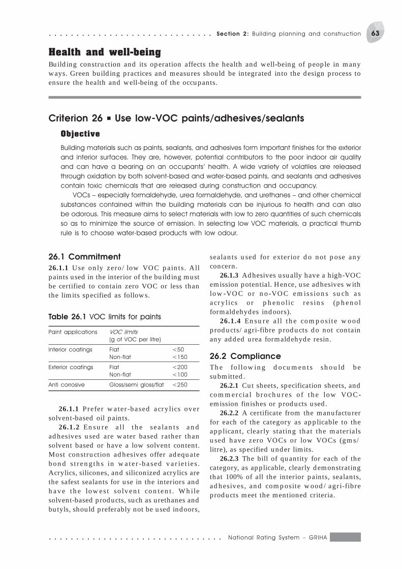
○ ○ ○ ○ ○ ○ ○ ○ ○ ○ ○ ○ ○ ○ ○ ○ ○ ○ ○ ○ ○ ○ ○ ○ ○ ○ ○ ○ ○ ○ ○ ○ National Rat ing System – GRIHA
63○ ○ ○ ○ ○ ○ ○ ○ ○ ○ ○ ○ ○ ○ ○ ○ ○ ○ ○ ○ ○ ○ ○ ○ ○ ○ ○ ○ ○ ○ Section 2: Bui lding planning and construct ion
Health and well-beingBuilding construction and its operation affects the health and well-being of people in manyways. Green building practices and measures should be integrated into the design process toensure the health and well-being of the occupants.
Criterion 26 P Use low-VOC paints/adhesives/sealants
Objective
Building materials such as paints, sealants, and adhesives form important finishes for the exterior
and interior surfaces. They are, however, potential contributors to the poor indoor air quality
and can have a bearing on an occupants’ health. A wide variety of volatiles are released
through oxidation by both solvent-based and water-based paints, and sealants and adhesives
contain toxic chemicals that are released during construction and occupancy.
VOCs – especially formaldehyde, urea formaldehyde, and urethanes – and other chemical
substances contained within the building materials can be injurious to health and can also
be odorous. This measure aims to select materials with low to zero quantities of such chemicals
so as to minimize the source of emission. In selecting low VOC materials, a practical thumb
rule is to choose water-based products with low odour.
26.1 Commitment
26.1.1 Use only zero/low VOC paints. Allpaints used in the interior of the building mustbe certified to contain zero VOC or less thanthe limits specified as follows.
Table 26.1 VOC limits for paints
Paint applications VOC limits
(g of VOC per litre)
Interior coatings Flat <50
Non-flat <150
Exterior coatings Flat <200
Non-flat <100
Anti corrosive Gloss/semi gloss/flat <250
26.1.1 Prefer water-based acrylics oversolvent-based oil paints.
26.1.2 Ensure all the sealants andadhesives used are water based rather thansolvent based or have a low solvent content.Most construction adhesives offer adequatebond strengths in water-based varieties.Acrylics, silicones, and siliconized acrylics arethe safest sealants for use in the interiors andhave the lowest solvent content. Whilesolvent-based products, such as urethanes andbutyls, should preferably not be used indoors,
sealants used for exterior do not pose anyconcern.
26.1.3 Adhesives usually have a high-VOCemission potential. Hence, use adhesives withlow-VOC or no-VOC emissions such asacrylics or phenolic resins (phenolformaldehydes indoors).
26.1.4 Ensure all the composite woodproducts/agri-fibre products do not containany added urea formaldehyde resin.
26.2 Compliance
The following documents should besubmitted.
26.2.1 Cut sheets, specification sheets, andcommercial brochures of the low VOC-emission finishes or products used.
26.2.2 A certificate from the manufacturerfor each of the category as applicable to theapplicant, clearly stating that the materialsused have zero VOCs or low VOCs (gms/litre), as specified under limits.
26.2.3 The bill of quantity for each of thecategory, as applicable, clearly demonstratingthat 100% of all the interior paints, sealants,adhesives, and composite wood/agri-fibreproducts meet the mentioned criteria.

National Rat ing System – GRIHA ○ ○ ○ ○ ○ ○ ○ ○ ○ ○ ○ ○ ○ ○ ○ ○ ○ ○ ○ ○ ○ ○ ○ ○ ○ ○ ○ ○ ○ ○ ○ ○
64 Section 2: Bui lding planning and construct ion ○ ○ ○ ○ ○ ○ ○ ○ ○ ○ ○ ○ ○ ○ ○ ○ ○ ○ ○ ○ ○ ○ ○ ○ ○ ○ ○ ○ ○ ○
26.3 Appraisal (maximum points – 4)
26.3.1 Zero/low-VOC paints: Zero/low-VOCpaints for 100% of all paint used in the interiorof the building (2 points), as per clauses 26.2.1,26.2.2, and 26.2.3.
26.3.2 Low-VOC sealants and adhesives: 100%of all the sealants and adhesives used are
water based rather than solvent based/low insolvent content, as per clauses 26.2.1, 26.2.2,and 26.2.3 (1 point).
26.3.3 100% of composite wood productswith no urea–formaldehyde resins, as perclauses 26.2.1, 26.2.2, and 26.2.3 (1 point).
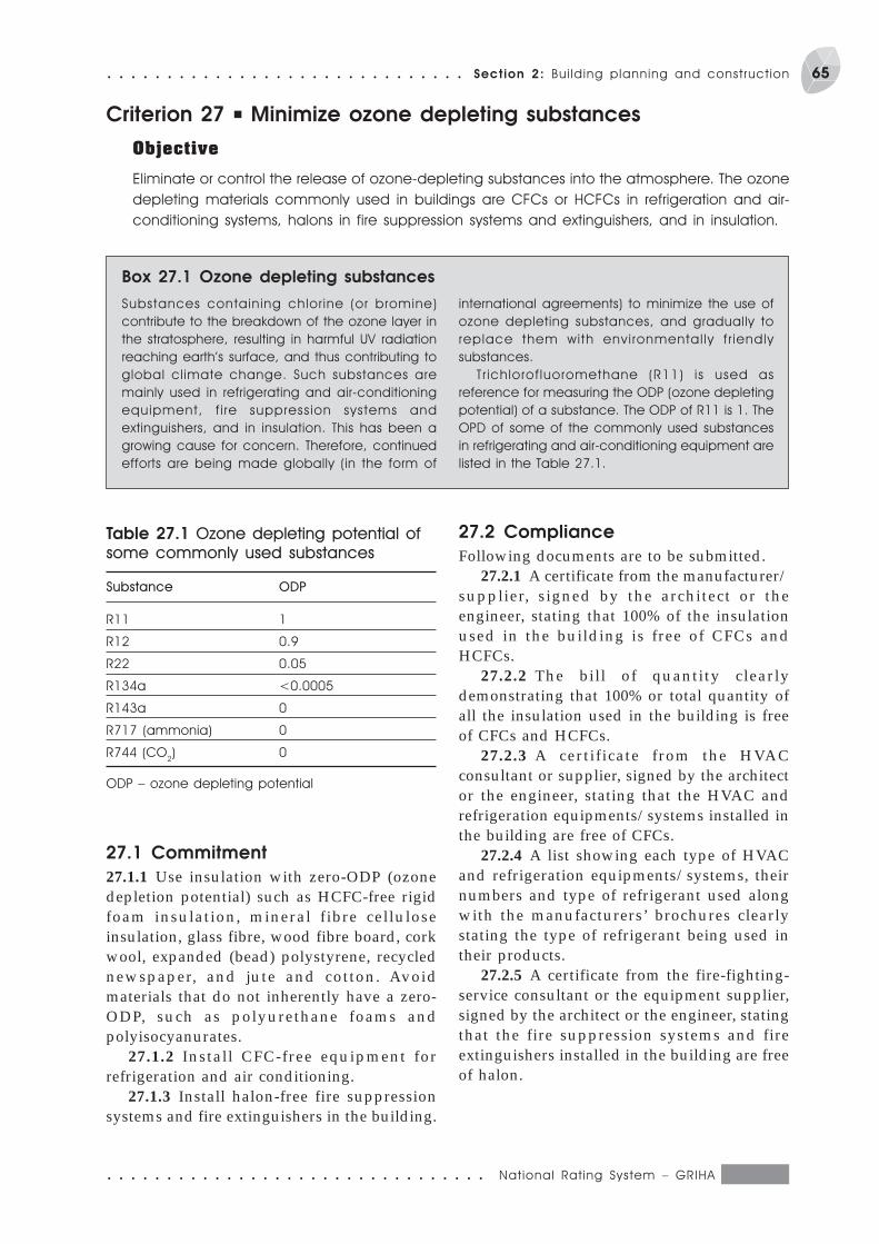
○ ○ ○ ○ ○ ○ ○ ○ ○ ○ ○ ○ ○ ○ ○ ○ ○ ○ ○ ○ ○ ○ ○ ○ ○ ○ ○ ○ ○ ○ ○ ○ National Rat ing System – GRIHA
65○ ○ ○ ○ ○ ○ ○ ○ ○ ○ ○ ○ ○ ○ ○ ○ ○ ○ ○ ○ ○ ○ ○ ○ ○ ○ ○ ○ ○ ○ Section 2: Bui lding planning and construct ion
Criterion 27 P Minimize ozone depleting substances
Objective
Eliminate or control the release of ozone-depleting substances into the atmosphere. The ozone
depleting materials commonly used in buildings are CFCs or HCFCs in refrigeration and air-
conditioning systems, halons in fire suppression systems and extinguishers, and in insulation.
Substances containing chlor ine (or bromine)
contribute to the breakdown of the ozone layer in
the stratosphere, resulting in harmful UV radiation
reaching earth’s surface, and thus contributing to
global climate change. Such substances are
mainly used in refrigerating and air-conditioning
equipment, f i re suppression systems and
extinguishers, and in insulation. This has been a
growing cause for concern. Therefore, continued
efforts are being made globally (in the form of
international agreements) to minimize the use of
ozone depleting substances, and gradually to
replace them with envi ronmental ly f r iendly
substances.
Tr ichlorof luoromethane (R11) is used as
reference for measuring the ODP (ozone depleting
potential) of a substance. The ODP of R11 is 1. The
OPD of some of the commonly used substances
in refrigerating and air-conditioning equipment are
listed in the Table 27.1.
Box 27.1 Ozone depleting substances
27.1 Commitment
27.1.1 Use insulation with zero-ODP (ozonedepletion potential) such as HCFC-free rigidfoam insulation, mineral fibre celluloseinsulation, glass fibre, wood fibre board, corkwool, expanded (bead) polystyrene, recyclednewspaper, and jute and cotton. Avoidmaterials that do not inherently have a zero-ODP, such as polyurethane foams andpolyisocyanurates.
27.1.2 Install CFC-free equipment forrefrigeration and air conditioning.
27.1.3 Install halon-free fire suppressionsystems and fire extinguishers in the building.
Table 27.1 Ozone depleting potential of
some commonly used substances
Substance ODP
R11 1
R12 0.9
R22 0.05
R134a <0.0005
R143a 0
R717 (ammonia) 0
R744 (CO2) 0
ODP – ozone depleting potential
27.2 Compliance
Following documents are to be submitted.27.2.1 A certificate from the manufacturer/
supplier, signed by the architect or theengineer, stating that 100% of the insulationused in the building is free of CFCs andHCFCs.
27.2.2 The bill of quantity clearlydemonstrating that 100% or total quantity ofall the insulation used in the building is freeof CFCs and HCFCs.
27.2.3 A certificate from the HVACconsultant or supplier, signed by the architector the engineer, stating that the HVAC andrefrigeration equipments/systems installed inthe building are free of CFCs.
27.2.4 A list showing each type of HVACand refrigeration equipments/systems, theirnumbers and type of refrigerant used alongwith the manufacturers’ brochures clearlystating the type of refrigerant being used intheir products.
27.2.5 A certificate from the fire-fighting-service consultant or the equipment supplier,signed by the architect or the engineer, statingthat the fire suppression systems and fireextinguishers installed in the building are freeof halon.

National Rat ing System – GRIHA ○ ○ ○ ○ ○ ○ ○ ○ ○ ○ ○ ○ ○ ○ ○ ○ ○ ○ ○ ○ ○ ○ ○ ○ ○ ○ ○ ○ ○ ○ ○ ○
66 Section 2: Bui lding planning and construct ion ○ ○ ○ ○ ○ ○ ○ ○ ○ ○ ○ ○ ○ ○ ○ ○ ○ ○ ○ ○ ○ ○ ○ ○ ○ ○ ○ ○ ○ ○
27.3 Appraisal (maximum points – 3)
27.3.1 All the insulation used in building areCFCs and HCFCs free, as per clauses 27.2.1and 27.2.2 (1 point).
27.3.2 All the HVAC and refrigerationequipment are CFCs free, as per clauses 27.2.3and 27.2.4 (1 point).
27.3.3 The fire suppression systems andfire extinguishers installed in the building arefree of halon, as per clause 27.2.5 (1 point).
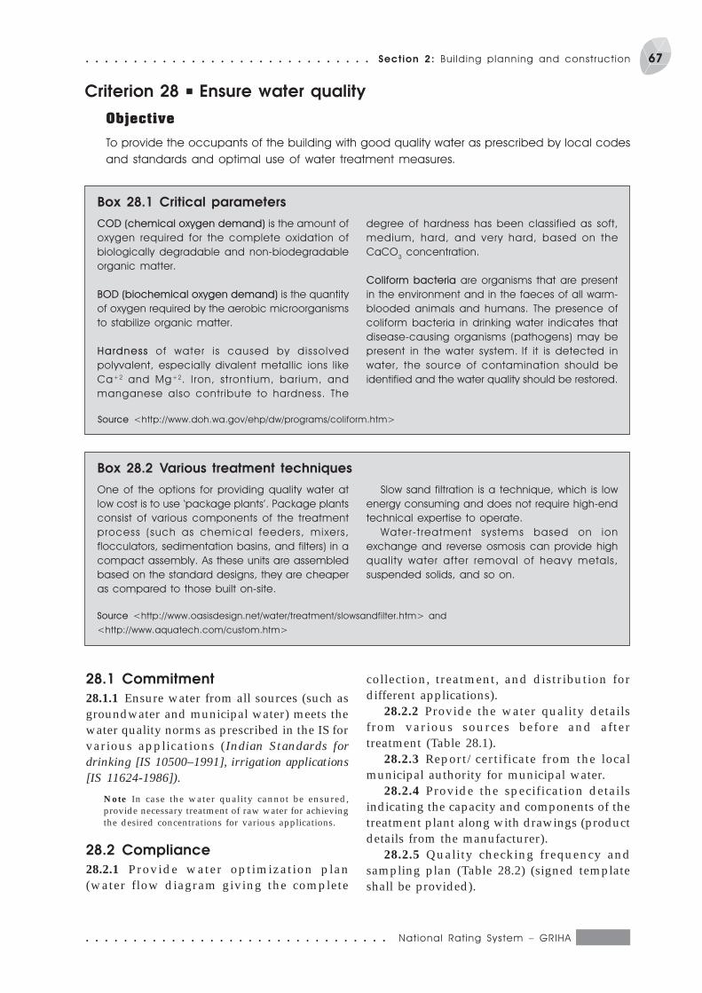
○ ○ ○ ○ ○ ○ ○ ○ ○ ○ ○ ○ ○ ○ ○ ○ ○ ○ ○ ○ ○ ○ ○ ○ ○ ○ ○ ○ ○ ○ ○ ○ National Rat ing System – GRIHA
67○ ○ ○ ○ ○ ○ ○ ○ ○ ○ ○ ○ ○ ○ ○ ○ ○ ○ ○ ○ ○ ○ ○ ○ ○ ○ ○ ○ ○ ○ Section 2: Bui lding planning and construct ion
Criterion 28 P Ensure water quality
Objective
To provide the occupants of the building with good quality water as prescribed by local codes
and standards and optimal use of water treatment measures.
COD (chemical oxygen demand) is the amount of
oxygen required for the complete oxidation of
biologically degradable and non-biodegradable
organic matter.
BOD (biochemical oxygen demand) is the quantity
of oxygen required by the aerobic microorganisms
to stabilize organic matter.
Hardness of water is caused by dissolved
polyvalent, especially divalent metallic ions like
Ca+2 and Mg+2. I ron, strontium, barium, and
manganese also contribute to hardness. The
degree of hardness has been classified as soft,
medium, hard, and very hard, based on the
CaCO3 concentration.
Coliform bacteria are organisms that are present
in the environment and in the faeces of all warm-
blooded animals and humans. The presence of
coliform bacteria in drinking water indicates that
disease-causing organisms (pathogens) may be
present in the water system. If it is detected in
water, the source of contamination should be
identified and the water quality should be restored.
Box 28.1 Critical parameters
28.1 Commitment
28.1.1 Ensure water from all sources (such asgroundwater and municipal water) meets thewater quality norms as prescribed in the IS forvarious applications (Indian Standards fordrinking [IS 10500–1991], irrigation applications[IS 11624-1986]).
Note In case the water quality cannot be ensured,provide necessary treatment of raw water for achievingthe desired concentrations for various applications.
28.2 Compliance
28.2.1 Provide water optimization plan(water flow diagram giving the complete
One of the options for providing quality water at
low cost is to use ‘package plants’. Package plants
consist of various components of the treatment
process (such as chemical feeders, mixers,
flocculators, sedimentation basins, and filters) in a
compact assembly. As these units are assembled
based on the standard designs, they are cheaper
as compared to those built on-site.
Slow sand filtration is a technique, which is low
energy consuming and does not require high-end
technical expertise to operate.
Water-t reatment systems based on ion
exchange and reverse osmosis can provide high
quality water after removal of heavy metals,
suspended solids, and so on.
Box 28.2 Various treatment techniques
Source <http://www.doh.wa.gov/ehp/dw/programs/coliform.htm>
Source <http://www.oasisdesign.net/water/treatment/slowsandfilter.htm> and
<http://www.aquatech.com/custom.htm>
collection, treatment, and distribution fordifferent applications).
28.2.2 Provide the water quality detailsfrom various sources before and aftertreatment (Table 28.1).
28.2.3 Report/certificate from the localmunicipal authority for municipal water.
28.2.4 Provide the specification detailsindicating the capacity and components of thetreatment plant along with drawings (productdetails from the manufacturer).
28.2.5 Quality checking frequency andsampling plan (Table 28.2) (signed templateshall be provided).

National Rat ing System – GRIHA ○ ○ ○ ○ ○ ○ ○ ○ ○ ○ ○ ○ ○ ○ ○ ○ ○ ○ ○ ○ ○ ○ ○ ○ ○ ○ ○ ○ ○ ○ ○ ○
68 Section 2: Bui lding planning and construct ion ○ ○ ○ ○ ○ ○ ○ ○ ○ ○ ○ ○ ○ ○ ○ ○ ○ ○ ○ ○ ○ ○ ○ ○ ○ ○ ○ ○ ○ ○
28.3 Appraisal (maximum points – 2)
28.3.1 Water quality conforming to ISstandards, as per clauses 28.2.1–28.2.5 (2 points).
Table 28.3 Water quality standards for
various applications
Parameter Drinking Irrigation,
water (IS industrial
10500:1991) cooling,
and so on
Total hardness (as CaCO3) 300 —
(mg/litre)
Total dissolved solids 500 2100
(mg/litre)
Chlorides as chlorine 250 500
(mg/litre)
Colour (hazen) 5 —
Turbidity (NTU) 5
Alkalinity (mg/ litre) 200
Calcium (as Ca), mg/litre 75
Table 28.1 Testing of water quality before and after treatment
Parameter Before treatment After treatment
Dissolved oxygen (mg/litre)
Biological oxygen demand (mg/litre)
Total coliform bacteria (MPN/100 ml)
Total dissolved solids (mg/litre)
Chloride as chlorine (mg/litre)
Colour
Boron (mg/litre)
Sulphates (mg/litre)
Nitrates (mg/litre)
pH
Arsenic (mg/litre)
Fluorides (mg/litre)
Iron (mg/litre)
Copper (mg/litre)
Lead (mg/litre)
Zinc (mg/litre)
MPN – most probable number
Table 28.2 Annual testing plan and frequency
Date Volume of sample (ml) Sample collection site Test lab. name
Inlet Outlet Other
Boron (mg/litre) 1 2
Sulphates (as SO4)(mg/litre) 200 1000
Nitrates (as NO3) (mg/litre) 45 –
Conductivity at 25 °C – 2.25
(us/cm)
pH 6.5–8.5 6.0–8.0
Anionic detergents as 0.2 –
MBAS (mg/ litre)
Arsenic (mg/litre) 0.05 –
Iron (mg/litre) 0.3 –
Fluorides (mg/litre) 1 –
Lead (mg/litre) 0.05 –
Copper (mg/litre) 0.05 –
Zinc (mg/litre) 5 –
Phenolic compounds (
as C6H5OH) (mg/litre) 0.001 –
Cyanide (mg/litre) 0.05 –
Chromium (mg/litre) 0.05 –
Parameter Drinking Irrigation,
water (IS industrial
10500:1991) cooling,
and so on.
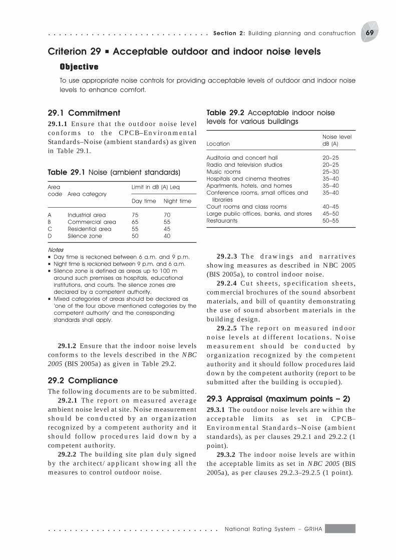
○ ○ ○ ○ ○ ○ ○ ○ ○ ○ ○ ○ ○ ○ ○ ○ ○ ○ ○ ○ ○ ○ ○ ○ ○ ○ ○ ○ ○ ○ ○ ○ National Rat ing System – GRIHA
69○ ○ ○ ○ ○ ○ ○ ○ ○ ○ ○ ○ ○ ○ ○ ○ ○ ○ ○ ○ ○ ○ ○ ○ ○ ○ ○ ○ ○ ○ Section 2: Bui lding planning and construct ion
Criterion 29 P Acceptable outdoor and indoor noise levels
Objective
To use appropriate noise controls for providing acceptable levels of outdoor and indoor noise
levels to enhance comfort.
29.1 Commitment
29.1.1 Ensure that the outdoor noise levelconforms to the CPCB–EnvironmentalStandards–Noise (ambient standards) as givenin Table 29.1.
Table 29.1 Noise (ambient standards)
Area Limit in dB (A) Leq
code Area category
Day time Night time
A Industrial area 75 70
B Commercial area 65 55
C Residential area 55 45
D Silence zone 50 40
Notes
P Day time is reckoned between 6 a.m. and 9 p.m.
P Night time is reckoned between 9 p.m. and 6 a.m.
P Silence zone is defined as areas up to 100 m
around such premises as hospitals, educational
institutions, and courts. The silence zones are
declared by a competent authority.
P Mixed categories of areas should be declared as
‘one of the four above mentioned categories by the
competent authority’ and the corresponding
standards shall apply.
29.1.2 Ensure that the indoor noise levelsconforms to the levels described in the NBC2005 (BIS 2005a) as given in Table 29.2.
29.2 Compliance
The following documents are to be submitted.29.2.1 The report on measured average
ambient noise level at site. Noise measurementshould be conducted by an organizationrecognized by a competent authority and itshould follow procedures laid down by acompetent authority.
29.2.2 The building site plan duly signedby the architect/applicant showing all themeasures to control outdoor noise.
29.2.3 The drawings and narrativesshowing measures as described in NBC 2005(BIS 2005a), to control indoor noise.
29.2.4 Cut sheets, specification sheets,commercial brochures of the sound absorbentmaterials, and bill of quantity demonstratingthe use of sound absorbent materials in thebuilding design.
29.2.5 The report on measured indoornoise levels at different locations. Noisemeasurement should be conducted byorganization recognized by the competentauthority and it should follow procedures laiddown by the competent authority (report to besubmitted after the building is occupied).
29.3 Appraisal (maximum points – 2)
29.3.1 The outdoor noise levels are within theacceptable limits as set in CPCB–Environmental Standards–Noise (ambientstandards), as per clauses 29.2.1 and 29.2.2 (1point).
29.3.2 The indoor noise levels are withinthe acceptable limits as set in NBC 2005 (BIS2005a), as per clauses 29.2.3–29.2.5 (1 point).
Table 29.2 Acceptable indoor noise
levels for various buildings
Noise level
Location dB (A)
Auditoria and concert hall 20–25
Radio and television studios 20–25
Music rooms 25–30
Hospitals and cinema theatres 35–40
Apartments, hotels, and homes 35–40
Conference rooms, small offices and 35–40
libraries
Court rooms and class rooms 40–45
Large public offices, banks, and stores 45–50
Restaurants 50–55
National Rat ing System – GRIHA ○ ○ ○ ○ ○ ○ ○ ○ ○ ○ ○ ○ ○ ○ ○ ○ ○ ○ ○ ○ ○ ○ ○ ○ ○ ○ ○ ○ ○ ○ ○ ○
70 Section 2: Bui lding planning and construct ion ○ ○ ○ ○ ○ ○ ○ ○ ○ ○ ○ ○ ○ ○ ○ ○ ○ ○ ○ ○ ○ ○ ○ ○ ○ ○ ○ ○ ○ ○
30.1 Commitment
30.1.1 In both an air-conditioned/non-air-conditioned buildings, ensure zero exposureof non-smokers to the tobacco smoke; prohibitsmoking on the building premises supportedwith the company policy.
30.1.2 Ensure that both air-conditioned/non-air-conditioned buildings provide adesignated smoking zone with a controlledenvironment that ensures restriction of thesmoke to the designated area, preferably in theperipheral spaces of the buildings or withinthe buildings (for multiple-occupancybuildings such as hotels, non-smoking andsmoking rooms to be clearly identified).
30.2 Compliance
The following documents should besubmitted.
30.2.1 Company policy for the ban/prohibition on smoking within the buildingpremises, if applicable, with the supportivedocuments verified and signed by aresponsible authority or
30.2.2 The building plan/interior layoutsigned by the architect, demonstrating theinternal planning for the smoke control bylocating the designated smoking zone on thebuilding periphery separated from the non-smoking areas by full height impermeableinternal partitions.
30.2.3 For a conditioned space, clearlydemonstrate with the help of the AC systemdesign documents, signed by the HVACconsultant or the site engineer, thatP designated smoking area is independent of
the non-smoking areas in the building.P smoking zone is exhausted directly to the
outdoors such that there is no recirculationof the tobacco smoke air to the non-smoking zone of the building.
Criterion 30 P Tobacco and smoke control
Objective
To put in place health strategies such as prohibiting smoking in the indoor areas/building or
providing designated/isolated smoking zones within the building designed with separate
ventilation systems with higher ventilation rates than the non-smoking areas. This will ensure
zero exposure of the non-smoking occupants to passive smoking.
P Smoking zone is operated on separateventilation systems, with higher ventilationrates than the non-smoking areas, and isdesigned for at least 60 cfm (cubic feet perminute)/person.
P Smoking zone operates at a negativepressure in comparison with thesurrounding non-smoking zone.
30.2.4 For a non-conditioned space, clearlydemonstrate in the internal floor plans/interior layout that the designated smokingzone is properly ventilated with theappropriate location of the air inlets/outlets.
30.2.5 For a non-conditioned space, clearlydemonstrate with the help of a designnarrativeP Designated smoking zone if mechanically
ventilated is designed for not less than 30ACH (air changes per hour).
P Smoking zone is properly ventilated and ata minimum, exhausted directly to theoutdoors, such that there is no recirculationof the tobacco smoke air to the non-smoking zone of the building.
P Properly enclosed with full height,impermeable internal partitions withrespect to the surrounding spaces.
30.3 Appraisal (maximum points – 1)
The following documents are to be submitted.30.3.1 Company policy for ban/prohibition
of smoking within the building premises, asper clause 30.2.1. or
30.3.2 A signed template by HVAC/architectural consultant certifying that allcompliances are met, as per clauses 30.2.2–30.2.5.
○ ○ ○ ○ ○ ○ ○ ○ ○ ○ ○ ○ ○ ○ ○ ○ ○ ○ ○ ○ ○ ○ ○ ○ ○ ○ ○ ○ ○ ○ ○ ○ National Rat ing System – GRIHA
71○ ○ ○ ○ ○ ○ ○ ○ ○ ○ ○ ○ ○ ○ ○ ○ ○ ○ ○ ○ ○ ○ ○ ○ ○ ○ ○ ○ ○ ○ Section 2: Bui lding planning and construct ion
Criterion 31 P Provide at least the minimum level of accessibilityfor persons with disabilities
Objective
To ensure accessibility and usability of the building and its facilities by employees, visitors, and
clients with disabilities.
31.1 Commitment
31.1.1 Ensure access to facilities and servicesby adopting appropriate site planning toeliminate barriers as per the recommendedstandards (NBC 2005 [BIS 2005f]), layout anddesigning of interior and exterior facilities asper principles of universal design such asprescribed by the National Building Code ofIndia, building management policies andprocedures, provision of auxiliary aids andappliances, and staff training in disabilityawareness. and
31.1.2 Comply with planning and designguidelines as outlined in NBC 2005 Annex D(Clause 12.21) (BIS 2005f).
31.2 Compliance
The following documents must be submitted.31.2.1 Signed letter by competent authority
P Al l bui lding maintenance programmes,
renovations, and refurbishments to address and
improvize accessibility features.
P Building management policies to ensure that
existing access provisions are not undermined
by housekeeping practices or by untrained staff.
P Periodically review the quality of accessibility by
conducting user feedback surveys and access
audits.
Examples of auxiliary aids/appliances
P Induction loop systems at all counters, reception
desks, meeting rooms, waiting areas, and so on.
P All printed information, brochures, and maps to
be made available in alternative formats such
as large print, audio, and Braille.
P Evacuation chairs to aid in assisted evacuation
of persons with impaired mobility.
P Audio/tactile signage and way finding systems
to aid in orientation and navigation of persons
with vision impairments.
Box 31.1 Some best practices for incorporating accessibility for persons withdisabilities
(architect/access auditor) to demonstratecompliance with NBC 2005 Annex D (Clause12.21) (BIS 2005f) and proposed additions.
31.2.2 Site photographs to demonstratecompliance.
31.2.3 Detailed narrative (not more than250 words) on provision of infrastructureaccessibility features, auxiliary aids andappliances, and appropriate buildingmanagement policies to ensure non-discrimination against persons withdisabilities.
31.3 Appraisal (maximum points – 1)
31.3.1 Compliance with National BuildingCode norms on Requirements for Planning ofPublic Buildings Meant for Use of PhysicallyChallenged, as per clauses 31.1.1 and 31.1.2(1 point).

S E C T I O N 3Building operation and
maintenance
The intention is to validate and maintain‘green’ performance levels/adopt andpropagate green practices and concepts.
It is important to monitor and verify themeasures and evaluate the criteria adopted in
the green design process; its actualperformance vis-à-vis predicted performance.It is also important to identify the need forupgradations/modifications in the systems.
Criterion 32 P Energy audit and validation
Objective
Validate the predicted energy consumption, thermal comfort, and visual comfort criteria.
32.1 Commitment
32.1.1 After occupying the building, get anenergy audit done by an energy auditorapproved by the BEE, Government of India,and submit the report to TERI.
32.1.2 Further, TERI will carry out thermalperformance monitoring and visual comfortmonitoring for typically representative days.This is primarily to verify the data providedin various documents, and for which pointshave already been awarded. All necessary
support in terms of travel, boarding, andlodging for carrying out the study has to beprovided to TERI executives.
32.2 Compliance and appraisal(mandatory and no points)
The following documents should be submitted.32.1.1 Energy audit report by an energy
auditor approved by the BEE, Government ofIndia.
National Rat ing System – GRIHA ○ ○ ○ ○ ○ ○ ○ ○ ○ ○ ○ ○ ○ ○ ○ ○ ○ ○ ○ ○ ○ ○ ○ ○ ○ ○ ○ ○ ○ ○ ○ ○
74 Section 3: Bui lding operat ion and maintenance ○ ○ ○ ○ ○ ○ ○ ○ ○ ○ ○ ○ ○ ○ ○ ○ ○ ○ ○ ○ ○ ○ ○ ○ ○ ○ ○ ○ ○
Criterion 33 P Operation and maintenance
Objective
To ascertain continued safety in the operation of the electrical and mechanical systems of
the building through proper maintenance by the owner or the occupants. This will be ensured
in the contract document by providing for the commissioning of all electrical and mechanical
systems by the respective supplier or builder. Moreover, the maintenance facilities will be carried
out by the respective facility management group, assigned by the owner or the occupants
themselves.
33.1 Commitment
33.1.1 Ensure a specific clause in the contractdocument for the commissioning andsystematic handing over of all electrical andmechanical systems to be maintained by theowner, supplier or operator.
33.1.2 Provide a core facility/servicemanagement group, if applicable, that will beresponsible for the O&M of the building’selectrical and mechanical systems aftercommissioning.
33.1.3 In case of small-scale/single-ownercommercial buildings, the owner or theoccupants themselves should undertake theresponsibility for the O&M of the building’selectrical and mechanical systems aftercommissioning.
33.1.4 Prepare a fully-documented O&Mmanual, CD, multimedia or an informationbrochure listing the best practices/dos anddon’ts/maintenance requirements for thebuilding’s electrical and mechanical systemsalong with the name and address of themanufacturer/supplier of the respectivesystem. This should be carried out by theowner/builder/occupants/service or facilitymanagement group.
33.2 Compliance
33.2.1 Applicant shall provide the proof ofprovision for commissioning of all electricaland mechanical systems to be maintained bythe owner, supplier or operator in the contractdocument or/and supportive documents,verified and signed by the responsible parties.
33.2.2 Applicant shall provide the proof ofprovision for a core facility/service groupresponsible for the O&M of the building’selectrical, and mechanical systems after thecommissioning. This should be supported withthe contract (mutually signed between therespective parties) document or supportivedocuments, verified and signed by theresponsible parties.
33.2.3 Submit a copy of the fullydocumented O&M manual, CD, multimedia orthe information brochure enlisting the bestpractices for O&M of the building’s electricaland mechanical systems. The name andaddress of the manufacturer/supplier of therespective system, owner/builder to be givento the occupants or to the service/facilitymanagement group at the time of occupation.
33.3 Appraisal (maximum points – 1)
Appendage of specific clause in the contractdocument for the commissioning of allelectrical and mechanical systems to bemaintained by the owner, supplier or operator,as per compliance clauses. Provision of a corefacility/service management group, ifapplicable, or the owners or occupantsthemselves (in the case of single ownercommercial buildings) undertaking theresponsibility for O&M of the building,documentation of the O&M best practices forthe building’s electrical and mechanicalsystems.
S E C T I O N 4Innovation points
The enlisted criteria in the rating systemare the most critical componentscontributing to the evolution of a green
building. Green building design and operationextend beyond the boundaries defined by therating system and may cover strategies andoptions that lead to environmental benefits.The purpose of this category of points is torecognize the measures adopted, whichcontribute to the overall objective of designingand maintaining of green buildings, and thosethat are otherwise not covered in the ratingsystem. The following is an indicative list ofinnovation points. The applicant may submitany other criterion, which they consider asdeserving for the award of points, under therating system. The applied criterion will beevaluated on the merits and demerits of itssustainability benefits. Each InnovationCriterion will carry one point, subject to amaximum of four points.
34.1 Environmental education
34.1.1 Objective
To promote awareness of significantenvironmental issues by impartingenvironmental education to the owner or theoccupants of the building and to thecommunity as a whole.
34.1.2 Commitment
34.1.2.1 Formulate a company policy onenvironmental education that facilitatesinstructional or environmental tours bykeeping the building open on weekends. Thetours may be supplemented with a smallvideo/multimedia presentation or adocumentary focusing on sustainablemeasures taken in the building design to saveenergy and to reduce the degree ofenvironmental impact.
34.1.2.2 Provide the owner/occupants orvisitors with brochures, CD, informationleaflets or a manual on environmentaleducation and concerned issues.
34.1.2.3 Create environmentalawareness through small efforts in thebuilding itself such as showcasing energy-efficient building systems, technologies, andmaterials, and properly labelling ordocumenting their respective energyperformance or savings. The building can alsobe equipped with data loggers and be put onextensive monitoring so that the performancedata for various building systems can be usedby students, researchers, and others, and thevisitors can observe the same.
34.1.2.4 Adopt innovative strategies suchas labelling the water fixtures for the watersource. For example, ‘this tap uses rainwater
Criterion 34 P Innovation points
National Rat ing System – GRIHA ○ ○ ○ ○ ○ ○ ○ ○ ○ ○ ○ ○ ○ ○ ○ ○ ○ ○ ○ ○ ○ ○ ○ ○ ○ ○ ○ ○ ○ ○ ○ ○
76 Section 4: Innovat ion points ○ ○ ○ ○ ○ ○ ○ ○ ○ ○ ○ ○ ○ ○ ○ ○ ○ ○ ○ ○ ○ ○ ○ ○ ○ ○ ○ ○ ○ ○ ○ ○ ○ ○ ○ ○ ○ ○ ○ ○ ○
harvested from the roof’. Also demonstratedifferent spaces connected with differentwaste-water treatment schemes with properdocumentation.
34.1.2.5 A landscape labelled for nativespecies or aromatic herbs, which would raiseawareness towards low maintenance and lowwater-consuming native species as comparedto high-maintenance exotic species.
34.1.2.6 Include a column onenvironmental awareness in the monthlynewsletter or newspaper of the company/organization.
34.1.3 Compliance
34.1.3.1 Applicants shall provide the proof ofthe company policy for the promotion ofenvironmental awareness, if applicable, withthe supportive documents verified and signedby a responsible authority.
34.1.3.2 Submit the building brochures,CD, information leaflets or properly compiledmanual, small video or documentary used tocreate awareness towards environmentalissues in the owner or the building occupants.
34.1.3.3 If applicable, applicants shall haveto provide a small narrative (300 words),supported with the photographs,demonstrating the innovative strategiesincorporated in the building, which raisesenvironmental awareness, such as labelling ordocumenting the low maintenance/less water-consuming species in landscaping andlabelling, and documenting the buildingsystems as per the efficient energyperformance and savings, or labelling thewater fixtures for harvested water source, andso on.
34.1.4 Appraisal (maximum points – 1)
34.1.4.1 Formulation of a company policy forthe promotion of environmental education orawareness in the form of instructional/environmental tours to the building, as perclause 34.2.1. and
34.1.4.2 Preparation of the buildingbrochures, CD, information leaflets orproperly compiled manual, small video ordocumentary on environmental education, asper clauses 34.2.2 and 34.2.3 (1 point).
34.2 Company policy on ‘greensupply chain’
34.2.1 Objective
To encourage company policies on the ‘greensupply chain’, so that the business uses themost efficient methods available for sourcing,manufacturing, and transporting and post-sales support for green building materials andproducts. This will serve as a ‘corporate accesssystem for sustainable development’– a single-source solution to meet the total logistics anddistribution needs which, in turn, will ensurethat the companies integrate the supply,manufacturing, and distribution of greenbuilding materials or products into sustainabledevelopment. As a result, this will facilitate asupply chain process to improve service,reduce or eliminate excess/fluctuatinginventories, shortages/stockouts, longer leadtimes, higher transportation andmanufacturing costs, and increase the flow ofinformation between the supply chainpartners by boosting supplier–to–customerrelations.
34.2.2 Commitment
34.2.2.1 Formulate a company policy on the‘green supply chain’, which will facilitatesourcing, manufacturing, transportation, andpost-sales support for green building materialsand products.
34.2.2.2 Set up a ‘corporate access systemfor sustainable development’, which will serveas an easy and single-source access to greenresources that can help enlist and search greensuppliers, vendors, and manufacturers acrossthe globe. This system can be put online sothat other corporate communities and researchorganizations working towards sustainabledevelopment and green building consultantscan share and enhance the services.
34.2.2.3 Corporate houses can form a smallgroup comprising of executives responsible forthe development and management of theglobal supply chain for the promotion ofsustainable development.
34.2.3 Compliance
34.2.3.1 Applicants shall provide proof ofcompany policy on ‘green supply chain’ for
○ ○ ○ ○ ○ ○ ○ ○ ○ ○ ○ ○ ○ ○ ○ ○ ○ ○ ○ ○ ○ ○ ○ ○ ○ ○ ○ ○ ○ ○ ○ ○ National Rat ing System – GRIHA
77○ ○ ○ ○ ○ ○ ○ ○ ○ ○ ○ ○ ○ ○ ○ ○ ○ ○ ○ ○ ○ ○ ○ ○ ○ ○ ○ ○ ○ ○ ○ ○ ○ ○ ○ ○ ○ ○ ○ ○ ○ Section 4: Innovat ion points
the promotion of sustainable development,terms of agreement with the single/association of vendors, suppliers ormanufacturers, if applicable, with thesupportive documents verified and signed bya responsible authority.
34.2.3.2 Applicants shall provide thedetails of the ‘corporate access system onsustainable development’ in any mode, asapplicable, either as a web page, database ora shared information service across thecorporate communities.
34.2.4 Appraisal (maximum points – 1)
34.2.4.1 Formulation of a company policy on‘green supply chain’ for the promotion ofsustainable development, demonstrating theterms of agreement with the single/association of vendors, suppliers ormanufacturers, if applicable, with thesupportive documents verified and signed bya responsible authority.
34.2.4.2 Development of a ‘corporateaccess system on sustainable development’either in paper or electronic media, or adatabase or a shared information serviceacross the corporate communities. Applicantsshall have to certify their association with theother corporate houses.
34.3 Integrated pest management
34.3.1 Objective
To develop and implement an integrated pestmanagement programme to control andmanage weeds and pests within tolerablelimits so as to achieve healthy growth forplants and people.
34.3.2 Commitment
34.3.2.1 Develop and implement a landscapemanagement/maintenance plan withemphasis on non-chemical based/organic pestmanagement.
34.3.2.2 Apply pesticides only ‘as needed’after prevention and physical controls havebeen implemented in the interiors.
34.2.6.3 Select the least hazardouspesticides for the control of targeted pests.
34.3.3 Compliance
34.3.3.1 Applicants shall demonstrate theintegration of pest management plan in thefacility or service management contract,verified with supportive documents andsigned by the responsible authority.
34.3.3.2 Applicants shall demonstrate theimplementation of pest management plan,including a monitoring plan and schedule.
34.3.4 Appraisal (maximum points – 1)
34.3.4.1 Integration of pest management planwith the maintenance plan as submitted by thecore facility or service management group.
34.4 Life cycle costing
34.4.1 Objective
To provide comprehensive lifecycle costanalysis of the project, considering the costsarising from owning, operating, maintaining,and others considered important for theproject viability.
34.4.2 Compliance
Applicants to provide a detailed life cycle costanalysis supporting the decisions made for theproject viability during its lifecycle.
34.4.3 Appraisal (maximum points – 1)
Life cycle cost analysis of the project.
34.5 Any other criteria proposed byapplicant
Submit any other criteria proposed byapplicant.
National Rat ing System – GRIHA ○ ○ ○ ○ ○ ○ ○ ○ ○ ○ ○ ○ ○ ○ ○ ○ ○ ○ ○ ○ ○ ○ ○ ○ ○ ○ ○ ○ ○ ○ ○ ○
78 Section 4: Innovat ion points ○ ○ ○ ○ ○ ○ ○ ○ ○ ○ ○ ○ ○ ○ ○ ○ ○ ○ ○ ○ ○ ○ ○ ○ ○ ○ ○ ○ ○ ○ ○ ○ ○ ○ ○ ○ ○ ○ ○ ○ ○
References
BIS (Bureau of Indian Standards). 2005fDevelopment Control Rules and GeneralBuilding RequirementsIn National Building Code of India 2005New Delhi: BIS
CPCB (Central Pollution Control Board). 1998Pollution Control Acts, Rules, and Notificationsissued thereunder, Vol. 1, pp. 311–312New Delhi: CPCB, Ministry of Environment andForests, Government of India. 501 pp.
Singh D, Chhoker P K, and Pandey R N. 2000Soil plant water analysis: a methods manualNew Delhi: Indian Agricultural ResearchInstitute, 160 pp.
ICAEN (Institut Català d’Energia). 2004aEfficient water management and waste watertreatment techniques, pp. 35–46In Design Manual: sustainable building, vol. 2,301 pp.New Delhi: TERI
ICAEN (Institut Català d’Energia). 2004bSite planning, pp. 17–34In Design Manual: sustainable building, vol. 2,301 pp.New Delhi: TERI
BIS (Bureau of Indian Standards). 2005aBuilding servicesIn National Building Code of India 2005New Delhi: BIS[Section 4: Acoustics, sound insulation, and noisecontrol]
BIS (Bureau of Indian Standards). 2005bPlumbing servicesIn National Building Code of India 2005New Delhi: BIS[Section 5: Installation of lifts and escalators, sub-section 5.5.11.2.1]
BIS (Bureau of Indian Standards). 2005cConstructional practices and safetyIn National Building Code of India 2005New Delhi: BIS
BIS (Bureau of Indian Standards). 2005dBuilding servicesIn National Building Code of India 2005New Delhi: BIS[Section 1: Lighting and ventilation]
BIS (Bureau of Indian Standards). 2005eBuilding servicesIn National Building Code of India 2005New Delhi: BIS[Section 3: Air conditioning, heating, andmechanical ventilation]