Tennant 5680 English Operator Manual - Caliber Equipment · Operator Manual 5680 *331176* 331176...
79
Walk-Behind Scrubber Operator Manual 5680 *331176* www.tennantco.com 331176 Rev. 02 (09-2008) North America / International (Electric) (SN# 10000000-- ) The Safe Scrubbing Alternativer
Transcript of Tennant 5680 English Operator Manual - Caliber Equipment · Operator Manual 5680 *331176* 331176...
Walk-Behind Scrubber
Operator Manual
5680
*331176*www.tennantco.com
331176Rev. 02 (09-2008)
North America / International
(Electric)(SN# 10000000-- )
The Safe Scrubbing Alternativer
This manual is furnished with each new model. It provides necessary operation and maintenance instructions.
Read this manual completely and understand the machine before operating or servicing it.
This machine will provide excellent service. However, the best results will be obtained at minimum costs if:
S The machine is operated with reasonable care.
S The machine is maintained regularly - per the machine maintenance instructions provided.
S The machine is maintained with manufacturer supplied or equivalent parts.
PROTECT THE ENVIRONMENTPlease dispose of packaging materials,old machine components such asbatteries, hazardous fluids, includingantifreeze and oil, in an environmentallysafe way according to local wastedisposal regulations.
Always remember to recycle.
MACHINE DATAPlease fill out at time of installation for future reference.
Model No. --
Serial No. --
Machine Options --
Sales Rep. --
Sales Rep. phone no. --
Customer Number --
Installation Date --
Tennant CompanyPO Box 1452Minneapolis, MN 55440Phone: (800) 553--8033 or (763) 513--2850www.tennantco.com
FaST--PAK is a US registered and unregistered trademark of Tennant Company.
Specifications and parts are subject to change without notice.
Copyright E 2006, 2008 TENNANT Company, Printed in U.S.A.
CONTENTS
15680 331176 (09--08)
CONTENTS
Page
SAFETY PRECAUTIONS 3. . . . . . . . . . . . . . . . .
OPERATION 5. . . . . . . . . . . . . . . . . . . . . . . . . . . .OPERATOR RESPONSIBILITY 5. . . . . . . .MACHINE COMPONENTS 6. . . . . . . . . . . .CONTROL PANEL SYMBOLS 7. . . . . . . . .CONTROLS AND INSTRUMENTS 8. . . . . .
STEERING HANDLES 9. . . . . . . . . . . . .ON-OFF KEY SWITCH 10. . . . . . . . . . . .SCRUB SWITCH 11. . . . . . . . . . . . . . . . .SCRUB HEADSTRAP (DISC HEAD) 11. . . . . . . . . . . .SQUEEGEE LEVER 11. . . . . . . . . . . . . . .HOURMETER 12. . . . . . . . . . . . . . . . . . . .BATTERY DISCHARGEINDICATOR 12. . . . . . . . . . . . . . . . . . . . .FaST SWITCH (OPTION) 12. . . . . . . . . .ec--H2O SWITCH (OPTION) 13. . . . . . .SOLUTION FLOW LEVER 14. . . . . . . . .CIRCUIT BREAKERS 14. . . . . . . . . . . . .SOLUTION TANK HOSE 15. . . . . . . . . . .RECOVERY TANK DRAIN HOSE 15. . .SUPPORT ARM 15. . . . . . . . . . . . . . . . . .STOP ARM 16. . . . . . . . . . . . . . . . . . . . . .SQUEEGEE DOWNPRESSURE CAMS 16. . . . . . . . . . . . . .
HOW THE MACHINE WORKS 17. . . . . . . . .FaST SCRUBBINGSYSTEM (OPTION) 18. . . . . . . . . . . . . .ec--H2O SYSTEM (OPTION) 19. . . . . . .
PRE-OPERATION CHECKLIST 20. . . . . . . .INSTALLING FaSTPAK AGENT (OPTION) 21. . . . . . . . . . . . . .STARTING THE MACHINE 23. . . . . . . . . . . .FILLING THE TANKS 23. . . . . . . . . . . . . . . . .NORMAL SCRUBBING 25. . . . . . . . . . . . . . .DOUBLE SCRUBBING 29. . . . . . . . . . . . . . . .STOP SCRUBBING 30. . . . . . . . . . . . . . . . . . .DRAINING AND CLEANINGTHE TANKS 31. . . . . . . . . . . . . . . . . . . . . . . .OPERATION ON INCLINES 35. . . . . . . . . . .STOP THE MACHINE 35. . . . . . . . . . . . . . . . .POST-OPERATION CHECKLIST 36. . . . . . .MACHINE TROUBLESHOOTING 37. . . . . . .
Page
MAINTENANCE 39. . . . . . . . . . . . . . . . . . . . . . . .MAINTENANCE CHART 39. . . . . . . . . . . . . . .LUBRICATION 41. . . . . . . . . . . . . . . . . . . . . . .
REAR CASTERS 41. . . . . . . . . . . . . . . . .TRANSAXLE 41. . . . . . . . . . . . . . . . . . . . .
BATTERIES 41. . . . . . . . . . . . . . . . . . . . . . . . .CHARGING THE BATTERIES 43. . . . . .
ELECTRIC MOTORS 44. . . . . . . . . . . . . . . . .SCRUB HEAD 45. . . . . . . . . . . . . . . . . . . . . . .
DISK BRUSH SCRUBHEAD SKIRT 45. . . . . . . . . . . . . . . . . . . .CYLINDRICAL BRUSHSCRUB HEAD SKIRTS 45. . . . . . . . . . .ADJUSTING THE SCRUBHEAD SKIRTS 45. . . . . . . . . . . . . . . . . .REPLACING THE SCRUBHEAD SKIRTS 45. . . . . . . . . . . . . . . . . .REMOVING OR REPLACING THESCRUB HEAD 46. . . . . . . . . . . . . . . . . . .LEVELING THE SCRUB HEAD 49. . . . .
SCRUB BRUSHES AND PADS 50. . . . . . . . .DISK BRUSHES 50. . . . . . . . . . . . . . . . . .REPLACING THE DISKBRUSHES OR PADS 50. . . . . . . . . . . . .CYLINDRICAL BRUSHES 53. . . . . . . . . .REPLACING THE CYLINDRICALBRUSHES 53. . . . . . . . . . . . . . . . . . . . . .CHECKING AND ADJUSTING
CYLINDRICAL BRUSH PATTERN 54. . . . . .SOLUTION SYSTEM 57. . . . . . . . . . . . . . . . .
RECOVERY TANK 57. . . . . . . . . . . . . . . .SOLUTION TANK 58. . . . . . . . . . . . . . . . .
FaST SYSTEM (OPTION) 59. . . . . . . . . . . . .FaST SYSTEM MAINTENANCE 59. . . .FaST SYSTEM FILTER SCREEN 60. . .FaST SUPPLY HOSE CONNECTOR 60
ec--H2O SYSTEM (OPTION) 61. . . . . . . . . . .ec--H2O MODULE FLUSHPROCEDURE 61. . . . . . . . . . . . . . . . . . .
SQUEEGEE 62. . . . . . . . . . . . . . . . . . . . . . . . .REMOVING THE SQUEEGEEASSEMBLY 62. . . . . . . . . . . . . . . . . . . . .INSTALLING THE SQUEEGEEASSEMBLY 63. . . . . . . . . . . . . . . . . . . . .LEVELING THE SQUEEGEE 63. . . . . . .ADJUSTING SQUEEGEEBLADE DEFLECTION 64. . . . . . . . . . . .
CONTENTS
5680 331176 (09--08)2
PageSQUEEGEE BLADES 65. . . . . . . . . . . . . . . . .
REPLACING OR ROTATINGTHE REAR SQUEEGEE BLADE 65. . .REPLACING OR ROTATING THEFRONT SQUEEGEE BLADE 66. . . . .
BELTS AND CHAINS 68. . . . . . . . . . . . . . . . .BRUSH DRIVE BELT 68. . . . . . . . . . . . . .STATIC DRAG CHAIN 68. . . . . . . . . . . . .
TIRES 68. . . . . . . . . . . . . . . . . . . . . . . . . . . . . . .PUSHING AND TRANSPORTINGTHE MACHINE 69. . . . . . . . . . . . . . . . . . . . . .
PUSHING THE MACHINE 69. . . . . . . . .TRANSPORTING THE MACHINE 69. . .
MACHINE JACKING 72. . . . . . . . . . . . . . . . . .STORAGE INFORMATION 72. . . . . . . . . . . .
FREEZE PROTECTION 72. . . . . . . . . . .
SPECIFICATIONS 74. . . . . . . . . . . . . . . . . . . . . .GENERAL MACHINEDIMENSIONS/CAPACITIES 74. . . . . . . . . . .FaST SYSTEM (OPTION) 75. . . . . . . . . . . . .ec--H2O SYSTEM (OPTION) 75. . . . . . . . . . .GENERAL MACHINEPERFORMANCE 75. . . . . . . . . . . . . . . . . . . .POWER TYPE 76. . . . . . . . . . . . . . . . . . . . . . .TIRES 76. . . . . . . . . . . . . . . . . . . . . . . . . . . . . . .MACHINE DIMENSIONS 77. . . . . . . . . . . . . .
SAFETY PRECAUTIONS
35680 331176 (9--06)
SAFETY PRECAUTIONS
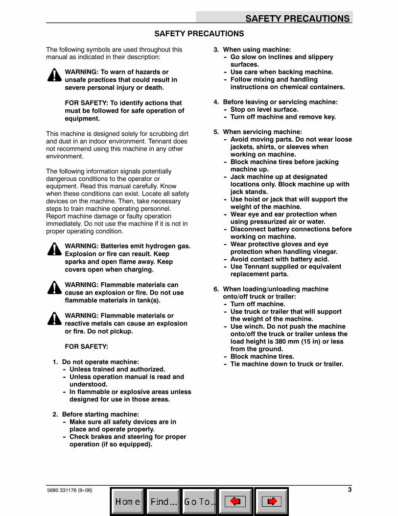
The following symbols are used throughout thismanual as indicated in their description:
WARNING: To warn of hazards orunsafe practices that could result insevere personal injury or death.
FOR SAFETY: To identify actions thatmust be followed for safe operation ofequipment.
This machine is designed solely for scrubbing dirtand dust in an indoor environment. Tennant doesnot recommend using this machine in any otherenvironment.
The following information signals potentiallydangerous conditions to the operator orequipment. Read this manual carefully. Knowwhen these conditions can exist. Locate all safetydevices on the machine. Then, take necessarysteps to train machine operating personnel.Report machine damage or faulty operationimmediately. Do not use the machine if it is not inproper operating condition.
WARNING: Batteries emit hydrogen gas.Explosion or fire can result. Keepsparks and open flame away. Keepcovers open when charging.
WARNING: Flammable materials cancause an explosion or fire. Do not useflammable materials in tank(s).
WARNING: Flammable materials orreactive metals can cause an explosionor fire. Do not pickup.
FOR SAFETY:
1. Do not operate machine:-- Unless trained and authorized.-- Unless operation manual is read andunderstood.
-- In flammable or explosive areas unlessdesigned for use in those areas.
2. Before starting machine:-- Make sure all safety devices are inplace and operate properly.
-- Check brakes and steering for properoperation (if so equipped).
3. When using machine:-- Go slow on inclines and slipperysurfaces.
-- Use care when backing machine.-- Follow mixing and handlinginstructions on chemical containers.
4. Before leaving or servicing machine:-- Stop on level surface.-- Turn off machine and remove key.
5. When servicing machine:-- Avoid moving parts. Do not wear loosejackets, shirts, or sleeves whenworking on machine.
-- Block machine tires before jackingmachine up.
-- Jack machine up at designatedlocations only. Block machine up withjack stands.
-- Use hoist or jack that will support theweight of the machine.
-- Wear eye and ear protection whenusing pressurized air or water.
-- Disconnect battery connections beforeworking on machine.
-- Wear protective gloves and eyeprotection when handling vinegar.
-- Avoid contact with battery acid.-- Use Tennant supplied or equivalentreplacement parts.
6. When loading/unloading machineonto/off truck or trailer:-- Turn off machine.-- Use truck or trailer that will supportthe weight of the machine.
-- Use winch. Do not push the machineonto/off the truck or trailer unless theload height is 380 mm (15 in) or lessfrom the ground.
-- Block machine tires.-- Tie machine down to truck or trailer.
SAFETY PRECAUTIONS
5680 331178 (9--06)4
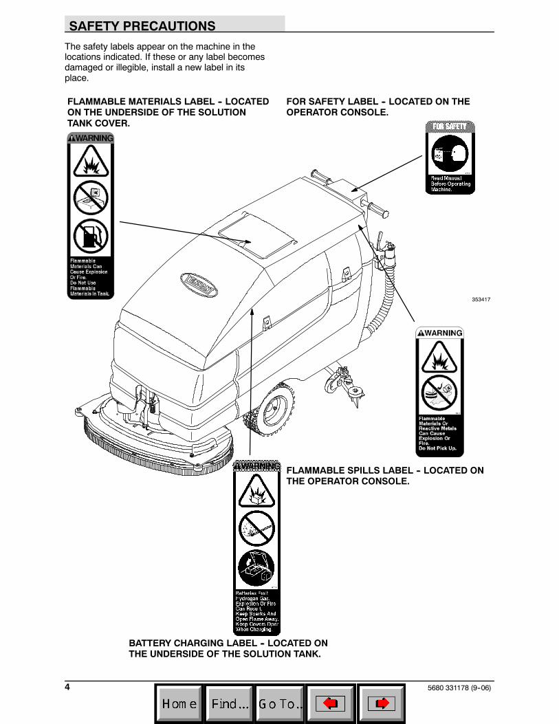
The safety labels appear on the machine in thelocations indicated. If these or any label becomesdamaged or illegible, install a new label in itsplace.
BATTERY CHARGING LABEL -- LOCATED ONTHE UNDERSIDE OF THE SOLUTION TANK.
FLAMMABLE SPILLS LABEL -- LOCATED ONTHE OPERATOR CONSOLE.
FOR SAFETY LABEL -- LOCATED ON THEOPERATOR CONSOLE.
FLAMMABLE MATERIALS LABEL -- LOCATEDON THE UNDERSIDE OF THE SOLUTIONTANK COVER.
353417
OPERATION
55680 331176 (9--06)
OPERATION
OPERATOR RESPONSIBILITY
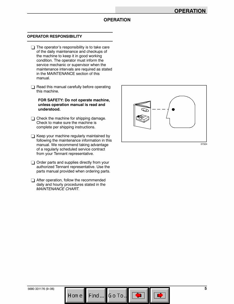
- The operator’s responsibility is to take careof the daily maintenance and checkups ofthe machine to keep it in good workingcondition. The operator must inform theservice mechanic or supervisor when themaintenance intervals are required as statedin the MAINTENANCE section of thismanual.
- Read this manual carefully before operatingthis machine.
FOR SAFETY: Do not operate machine,unless operation manual is read andunderstood.
- Check the machine for shipping damage.Check to make sure the machine iscomplete per shipping instructions.
- Keep your machine regularly maintained byfollowing the maintenance information in thismanual. We recommend taking advantageof a regularly scheduled service contractfrom your Tennant representative.
- Order parts and supplies directly from yourauthorized Tennant representative. Use theparts manual provided when ordering parts.
- After operation, follow the recommendeddaily and hourly procedures stated in theMAINTENANCE CHART.
07324
OPERATION
5680 331176 (09--08)6
MACHINE COMPONENTS
A D
E
F
G
H
I
KC
M
L
A
B
C
J
N O PQ
M
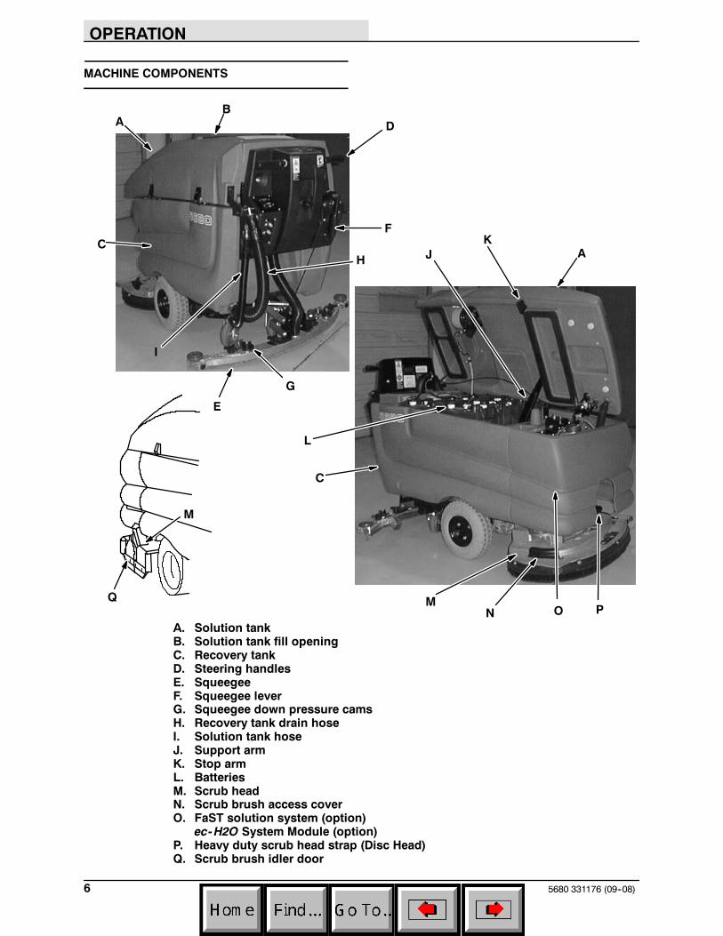
A. Solution tankB. Solution tank fill openingC. Recovery tankD. Steering handlesE. SqueegeeF. Squeegee leverG. Squeegee down pressure camsH. Recovery tank drain hoseI. Solution tank hoseJ. Support armK. Stop armL. BatteriesM. Scrub headN. Scrub brush access coverO. FaST solution system (option)
ec-H2O System Module (option)P. Heavy duty scrub head strap (Disc Head)Q. Scrub brush idler door
OPERATION
75680 331176 (09--08)
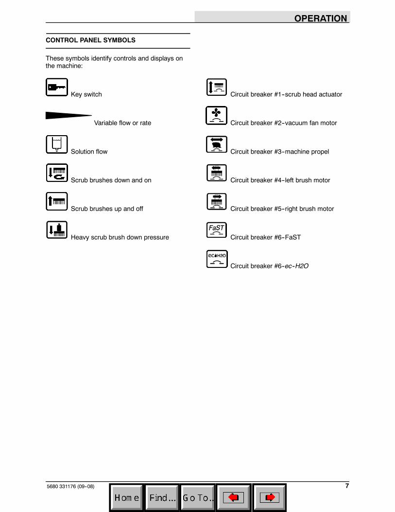
CONTROL PANEL SYMBOLS
These symbols identify controls and displays onthe machine:
Key switch Circuit breaker #1--scrub head actuator
Variable flow or rate Circuit breaker #2--vacuum fan motor
Solution flow Circuit breaker #3--machine propel
Scrub brushes down and on Circuit breaker #4--left brush motor
Scrub brushes up and off Circuit breaker #5--right brush motor
Heavy scrub brush down pressure Circuit breaker #6--FaST
Circuit breaker #6--ec--H2O
OPERATION
5680 331176 (09--08)8
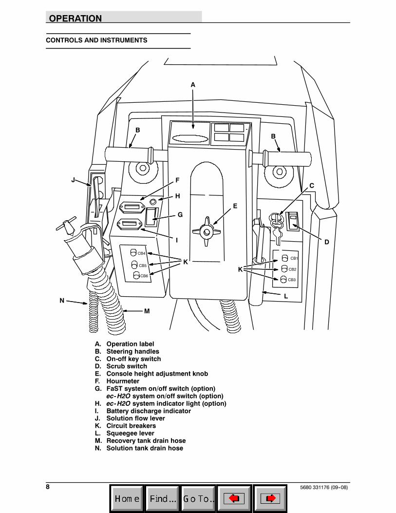
CONTROLS AND INSTRUMENTS
CB1
CB2
CB3
CB4
CB5
B
D
EG
I
J
K
B
L
M
C
A
H
CB6
K
N
F
A. Operation labelB. Steering handlesC. On-off key switchD. Scrub switchE. Console height adjustment knobF. HourmeterG. FaST system on/off switch (option)
ec-H2O system on/off switch (option)H. ec-H2O system indicator light (option)I. Battery discharge indicatorJ. Solution flow leverK. Circuit breakersL. Squeegee leverM. Recovery tank drain hoseN. Solution tank drain hose
OPERATION
95680 331176 (9--06)
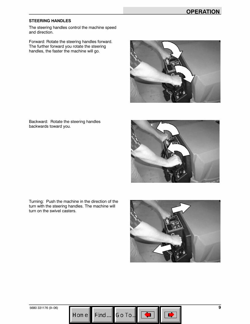
STEERING HANDLES
The steering handles control the machine speedand direction.
Forward: Rotate the steering handles forward.The further forward you rotate the steeringhandles, the faster the machine will go.
Backward: Rotate the steering handlesbackwards toward you.
Turning: Push the machine in the direction of theturn with the steering handles. The machine willturn on the swivel casters.
OPERATION
5680 331176 (9--06)10
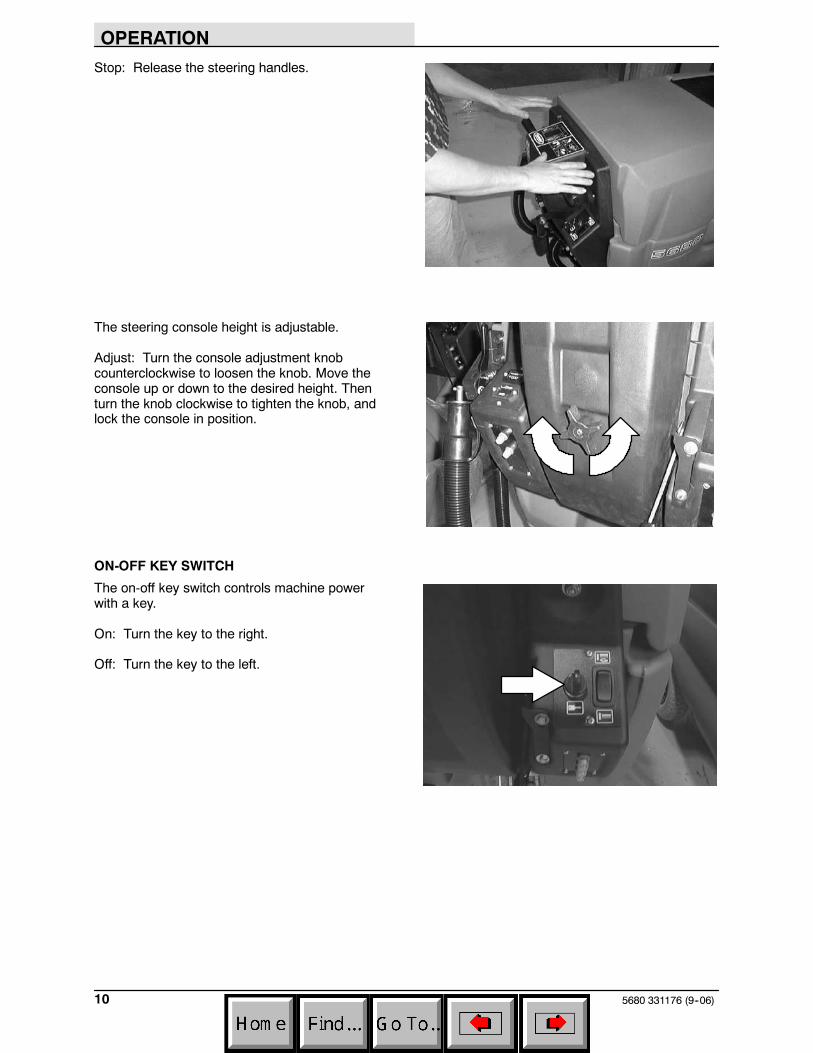
Stop: Release the steering handles.
The steering console height is adjustable.
Adjust: Turn the console adjustment knobcounterclockwise to loosen the knob. Move theconsole up or down to the desired height. Thenturn the knob clockwise to tighten the knob, andlock the console in position.
ON-OFF KEY SWITCH
The on-off key switch controls machine powerwith a key.
On: Turn the key to the right.
Off: Turn the key to the left.
OPERATION
115680 331176 (09--08)
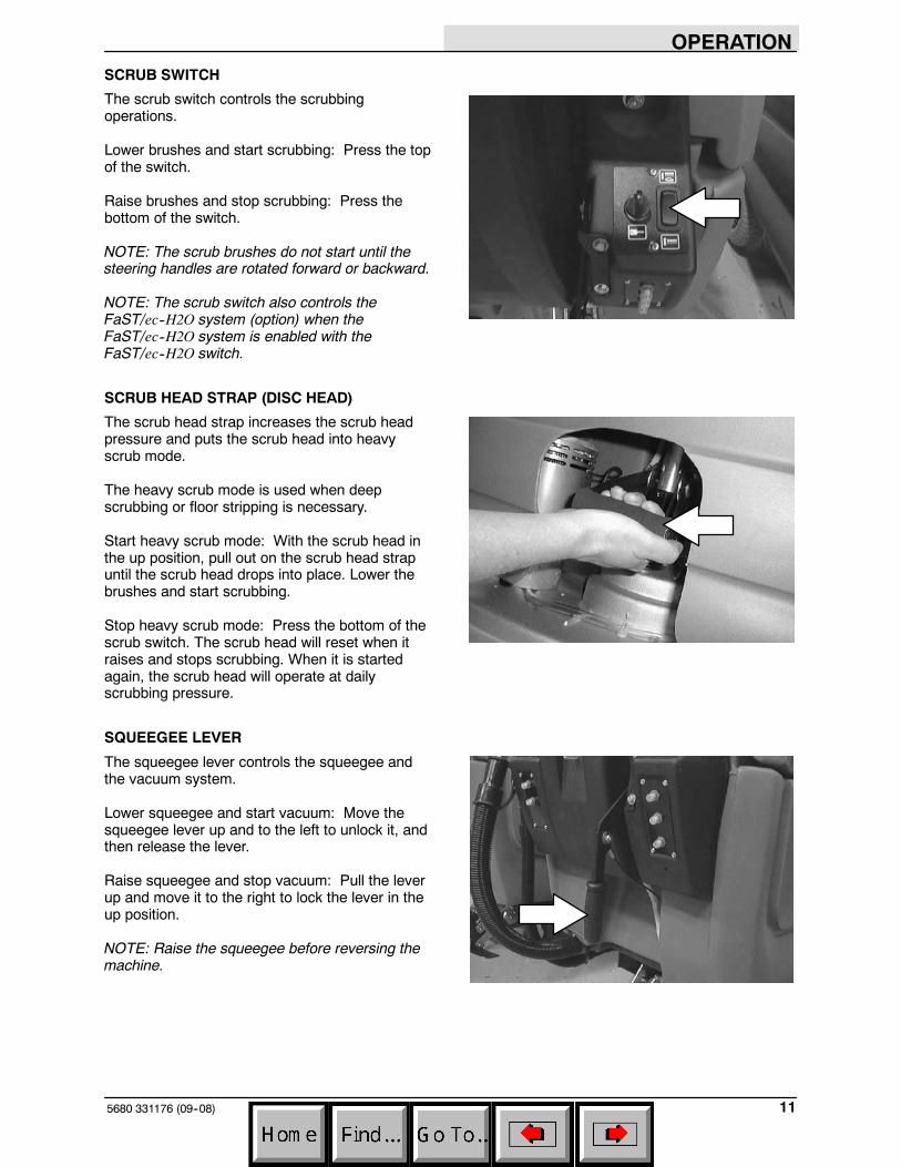
SCRUB SWITCH
The scrub switch controls the scrubbingoperations.
Lower brushes and start scrubbing: Press the topof the switch.
Raise brushes and stop scrubbing: Press thebottom of the switch.
NOTE: The scrub brushes do not start until thesteering handles are rotated forward or backward.
NOTE: The scrub switch also controls theFaST/ec--H2O system (option) when theFaST/ec--H2O system is enabled with theFaST/ec--H2O switch.
SCRUB HEAD STRAP (DISC HEAD)
The scrub head strap increases the scrub headpressure and puts the scrub head into heavyscrub mode.
The heavy scrub mode is used when deepscrubbing or floor stripping is necessary.
Start heavy scrub mode: With the scrub head inthe up position, pull out on the scrub head strapuntil the scrub head drops into place. Lower thebrushes and start scrubbing.
Stop heavy scrub mode: Press the bottom of thescrub switch. The scrub head will reset when itraises and stops scrubbing. When it is startedagain, the scrub head will operate at dailyscrubbing pressure.
SQUEEGEE LEVER
The squeegee lever controls the squeegee andthe vacuum system.
Lower squeegee and start vacuum: Move thesqueegee lever up and to the left to unlock it, andthen release the lever.
Raise squeegee and stop vacuum: Pull the leverup and move it to the right to lock the lever in theup position.
NOTE: Raise the squeegee before reversing themachine.
OPERATION
5680 331176 (9--06)12
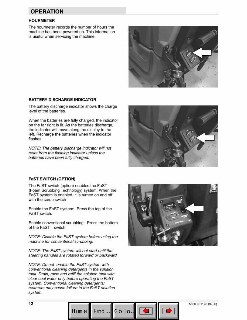
HOURMETER
The hourmeter records the number of hours themachine has been powered on. This informationis useful when servicing the machine.
BATTERY DISCHARGE INDICATOR
The battery discharge indicator shows the chargelevel of the batteries.
When the batteries are fully charged, the indicatoron the far right is lit. As the batteries discharge,the indicator will move along the display to theleft. Recharge the batteries when the indicatorflashes.
NOTE: The battery discharge indicator will notreset from the flashing indicator unless thebatteries have been fully charged.
FaST SWITCH (OPTION)
The FaST switch (option) enables the FaST(Foam Scrubbing Technology) system. When theFaST system is enabled, it is turned on and offwith the scrub switch
Enable the FaST system: Press the top of theFaST switch.
Enable conventional scrubbing: Press the bottomof the FaST switch.
NOTE: Disable the FaST system before using themachine for conventional scrubbing.
NOTE: The FaST system will not start until thesteering handles are rotated forward or backward.
NOTE: Do not enable the FaST system withconventional cleaning detergents in the solutiontank. Drain, raise and refill the solution tank withclear cool water only before operating the FaSTsystem. Conventional cleaning detergents/restorers may cause failure to the FaST solutionsystem.
OPERATION
135680 331176 (09--08)
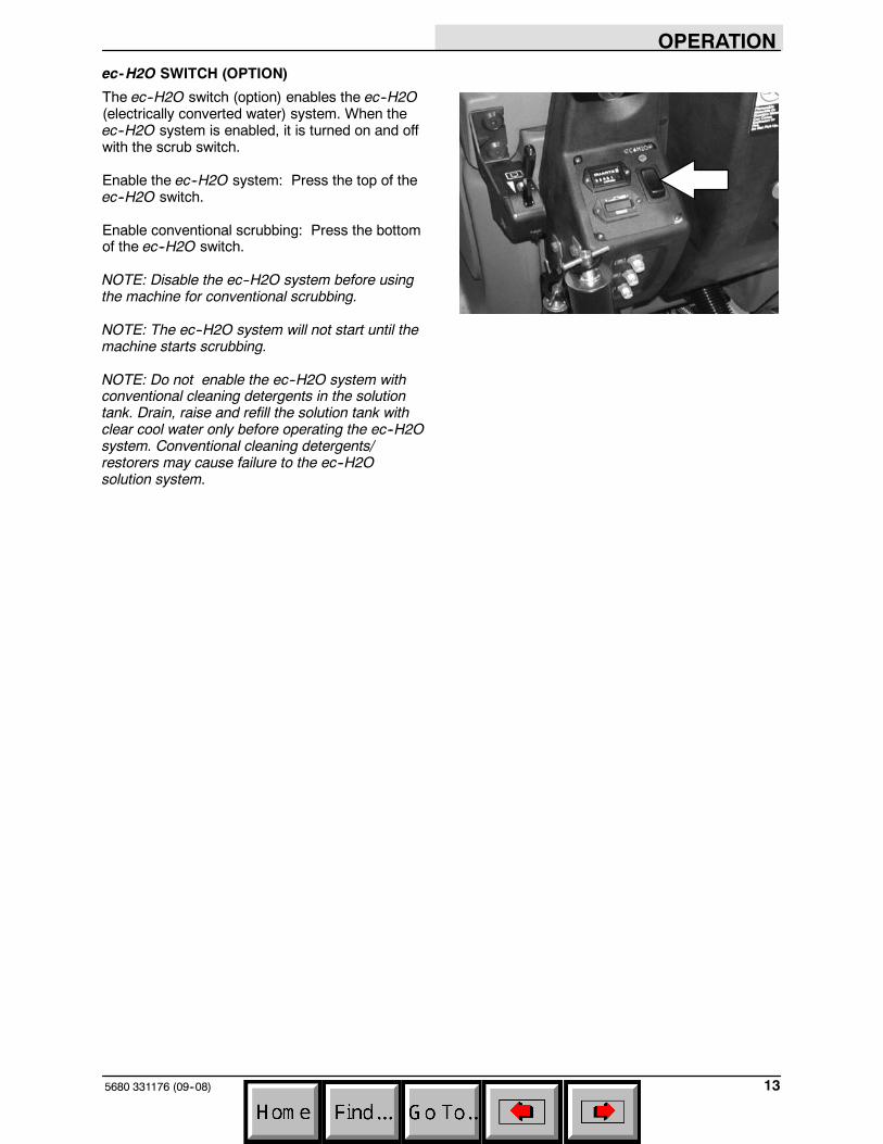
ec-H2O SWITCH (OPTION)
The ec--H2O switch (option) enables the ec--H2O(electrically converted water) system. When theec--H2O system is enabled, it is turned on and offwith the scrub switch.
Enable the ec--H2O system: Press the top of theec--H2O switch.
Enable conventional scrubbing: Press the bottomof the ec--H2O switch.
NOTE: Disable the ec--H2O system before usingthe machine for conventional scrubbing.
NOTE: The ec--H2O system will not start until themachine starts scrubbing.
NOTE: Do not enable the ec--H2O system withconventional cleaning detergents in the solutiontank. Drain, raise and refill the solution tank withclear cool water only before operating the ec--H2Osystem. Conventional cleaning detergents/restorers may cause failure to the ec--H2Osolution system.
OPERATION
5680 331176 (09--08)14
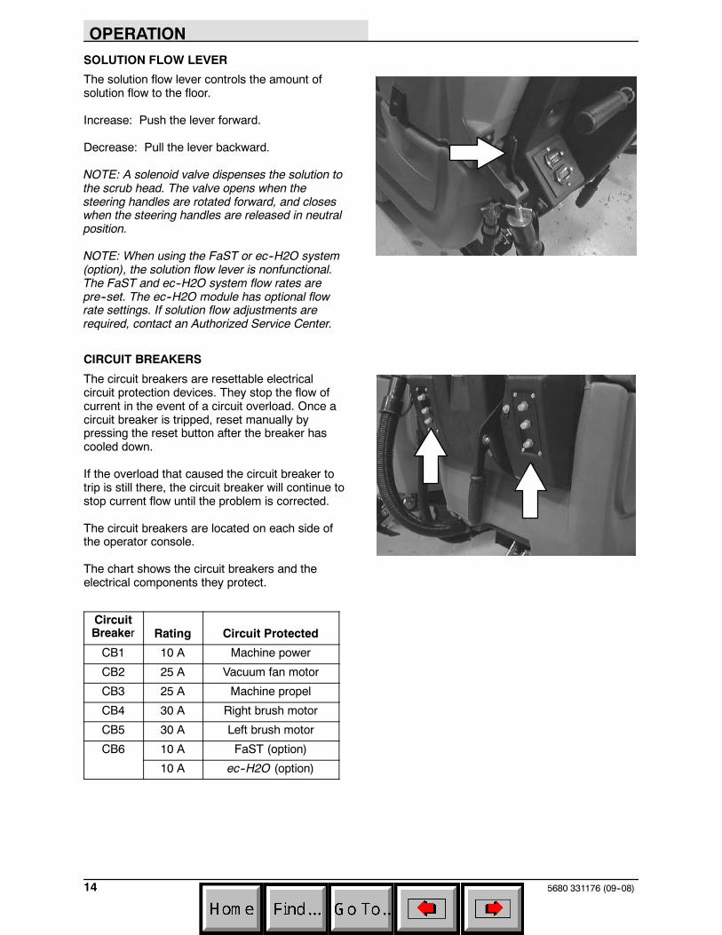
SOLUTION FLOW LEVER
The solution flow lever controls the amount ofsolution flow to the floor.
Increase: Push the lever forward.
Decrease: Pull the lever backward.
NOTE: A solenoid valve dispenses the solution tothe scrub head. The valve opens when thesteering handles are rotated forward, and closeswhen the steering handles are released in neutralposition.
NOTE: When using the FaST or ec--H2O system(option), the solution flow lever is nonfunctional.The FaST and ec--H2O system flow rates arepre--set. The ec--H2O module has optional flowrate settings. If solution flow adjustments arerequired, contact an Authorized Service Center.
CIRCUIT BREAKERS
The circuit breakers are resettable electricalcircuit protection devices. They stop the flow ofcurrent in the event of a circuit overload. Once acircuit breaker is tripped, reset manually bypressing the reset button after the breaker hascooled down.
If the overload that caused the circuit breaker totrip is still there, the circuit breaker will continue tostop current flow until the problem is corrected.
The circuit breakers are located on each side ofthe operator console.
The chart shows the circuit breakers and theelectrical components they protect.
CircuitBreaker Rating Circuit Protected
CB1 10 A Machine power
CB2 25 A Vacuum fan motor
CB3 25 A Machine propel
CB4 30 A Right brush motor
CB5 30 A Left brush motor
CB6 10 A FaST (option)
10 A ec--H2O (option)
OPERATION
155680 331176 (9--06)
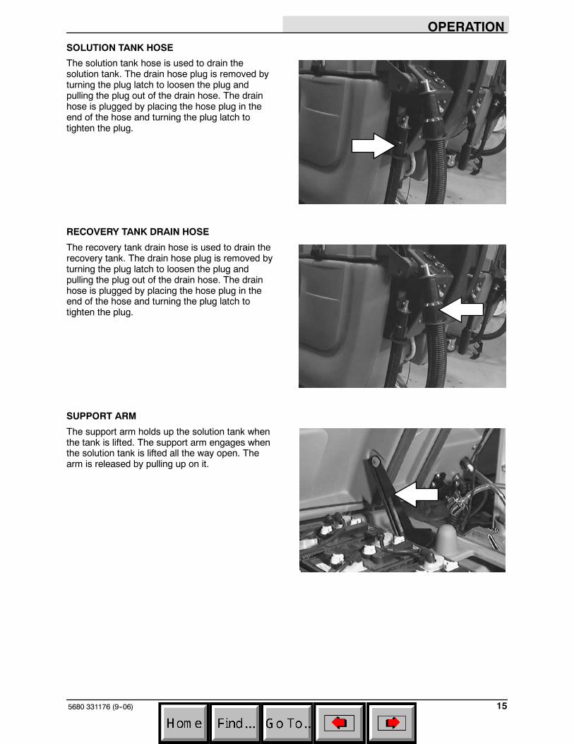
SOLUTION TANK HOSE
The solution tank hose is used to drain thesolution tank. The drain hose plug is removed byturning the plug latch to loosen the plug andpulling the plug out of the drain hose. The drainhose is plugged by placing the hose plug in theend of the hose and turning the plug latch totighten the plug.
RECOVERY TANK DRAIN HOSE
The recovery tank drain hose is used to drain therecovery tank. The drain hose plug is removed byturning the plug latch to loosen the plug andpulling the plug out of the drain hose. The drainhose is plugged by placing the hose plug in theend of the hose and turning the plug latch totighten the plug.
SUPPORT ARM
The support arm holds up the solution tank whenthe tank is lifted. The support arm engages whenthe solution tank is lifted all the way open. Thearm is released by pulling up on it.
OPERATION
5680 331176 (9--06)16
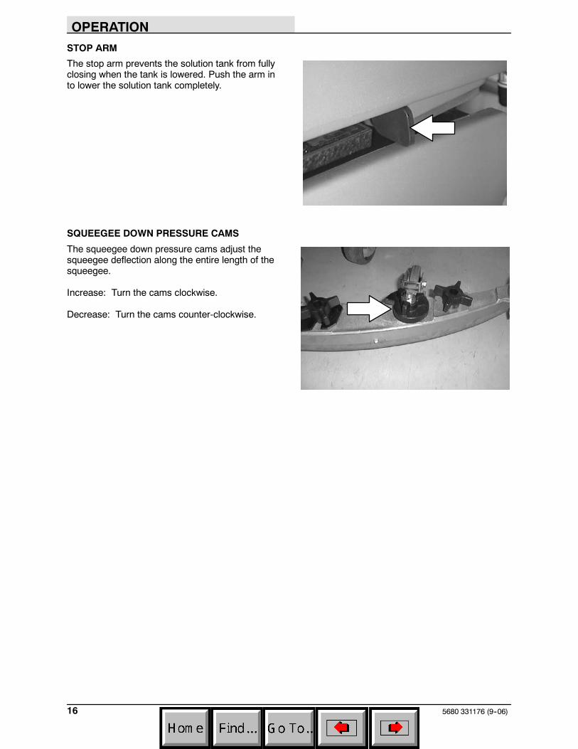
STOP ARM
The stop arm prevents the solution tank from fullyclosing when the tank is lowered. Push the arm into lower the solution tank completely.
SQUEEGEE DOWN PRESSURE CAMS
The squeegee down pressure cams adjust thesqueegee deflection along the entire length of thesqueegee.
Increase: Turn the cams clockwise.
Decrease: Turn the cams counter-clockwise.
OPERATION
175680 331176 (9--06)
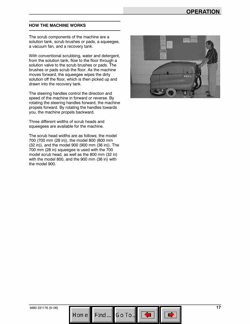
HOW THE MACHINE WORKS
The scrub components of the machine are asolution tank, scrub brushes or pads, a squeegee,a vacuum fan, and a recovery tank.
With conventional scrubbing, water and detergent,from the solution tank, flow to the floor through asolution valve to the scrub brushes or pads. Thebrushes or pads scrub the floor. As the machinemoves forward, the squeegee wipes the dirtysolution off the floor, which is then picked up anddrawn into the recovery tank.
The steering handles control the direction andspeed of the machine in forward or reverse. Byrotating the steering handles forward, the machinepropels forward. By rotating the handles towardsyou, the machine propels backward.
Three different widths of scrub heads andsqueegees are available for the machine.
The scrub head widths are as follows; the model700 (700 mm (28 in)), the model 800 (800 mm(32 in)), and the model 900 (900 mm (36 in)). The700 mm (28 in) squeegee is used with the 700model scrub head, as well as the 800 mm (32 in)with the model 800, and the 900 mm (36 in) withthe model 900.
OPERATION
5680 331176 (3--08)18
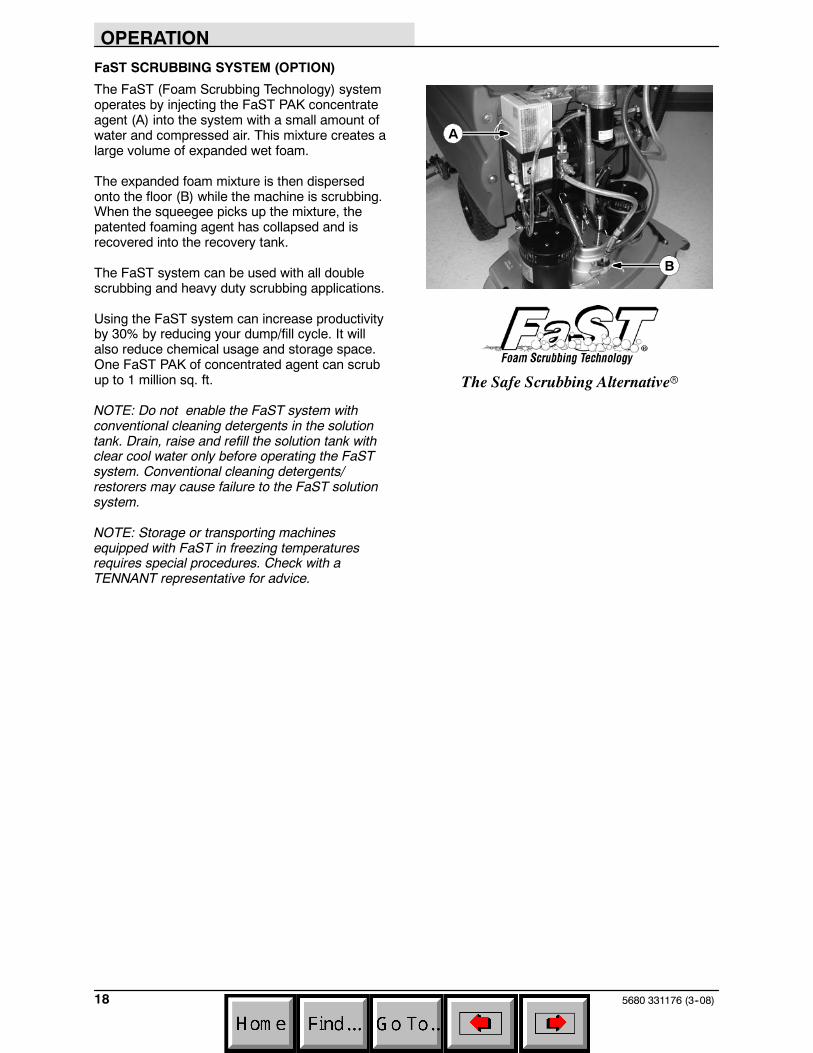
FaST SCRUBBING SYSTEM (OPTION)
The FaST (Foam Scrubbing Technology) systemoperates by injecting the FaST PAK concentrateagent (A) into the system with a small amount ofwater and compressed air. This mixture creates alarge volume of expanded wet foam.
The expanded foam mixture is then dispersedonto the floor (B) while the machine is scrubbing.When the squeegee picks up the mixture, thepatented foaming agent has collapsed and isrecovered into the recovery tank.
The FaST system can be used with all doublescrubbing and heavy duty scrubbing applications.
Using the FaST system can increase productivityby 30% by reducing your dump/fill cycle. It willalso reduce chemical usage and storage space.One FaST PAK of concentrated agent can scrubup to 1 million sq. ft.
NOTE: Do not enable the FaST system withconventional cleaning detergents in the solutiontank. Drain, raise and refill the solution tank withclear cool water only before operating the FaSTsystem. Conventional cleaning detergents/restorers may cause failure to the FaST solutionsystem.
NOTE: Storage or transporting machinesequipped with FaST in freezing temperaturesrequires special procedures. Check with aTENNANT representative for advice.
B
A
The Safe Scrubbing Alternativer
OPERATION
195680 331176 (09--08)
ec-H2O SYSTEM (OPTION)
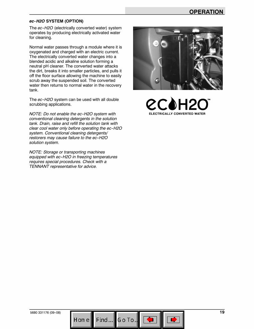
The ec--H2O (electrically converted water) systemoperates by producing electrically activated waterfor cleaning.
Normal water passes through a module where it isoxygenated and charged with an electric current.The electrically converted water changes into ablended acidic and alkaline solution forming aneutral pH cleaner. The converted water attacksthe dirt, breaks it into smaller particles, and pulls itoff the floor surface allowing the machine to easilyscrub away the suspended soil. The convertedwater then returns to normal water in the recoverytank.
The ec--H2O system can be used with all doublescrubbing applications.
NOTE: Do not enable the ec--H2O system withconventional cleaning detergents in the solutiontank. Drain, raise and refill the solution tank withclear cool water only before operating the ec--H2Osystem. Conventional cleaning detergents/restorers may cause failure to the ec--H2Osolution system.
NOTE: Storage or transporting machinesequipped with ec--H2O in freezing temperaturesrequires special procedures. Check with aTENNANT representative for advice.
OPERATION
5680 331176 (09--08)20
PRE-OPERATION CHECKLIST
Check over this list of items before operating themachine:
- Check under the machine for leaks.
- Check for wire, string, or twine wrappedaround the scrub brushes.
- Check the squeegees for wear or damage.
- Check the squeegee suction hose forobstructions.
- Check the recovery tank cover seals forwear or damage.
- Check that the vacuum fan inlet filter isclean.
- FaST Scrubbing: Check the FaST PAK(option) concentrate agent level, replacecarton as needed. See the INSTALLINGTHE FaST PAK AGENT section of themanual.
- FaST or ec-H2O Scrubbing: Check that allconventional cleaning agents/restorers aredrained and rinsed from the solution tank.
- FaST or ec-H2O Scrubbing: Check thatsolution tank is filled with clear cool wateronly.
OPERATION
215680 331176 (9--06)
INSTALLING FaST PAK AGENT (OPTION)
NOTE: Machine must be equipped with the FaSToption before the FaST PAK agent can beinstalled.
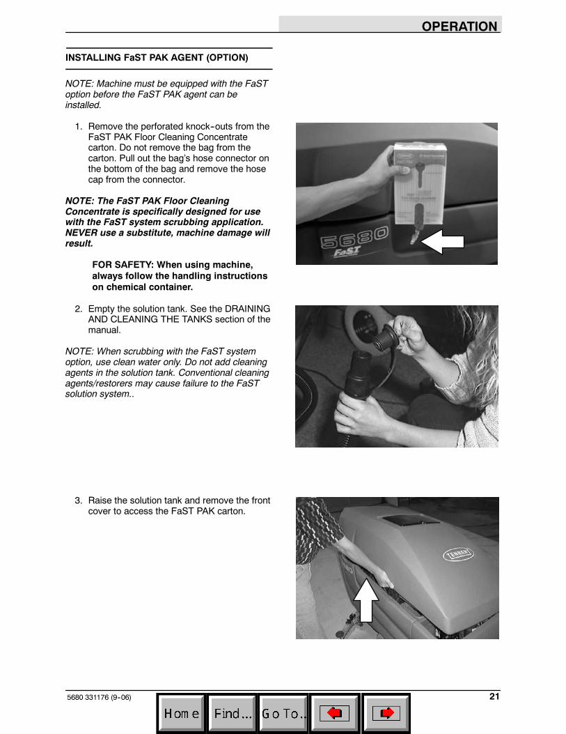
1. Remove the perforated knock--outs from theFaST PAK Floor Cleaning Concentratecarton. Do not remove the bag from thecarton. Pull out the bag’s hose connector onthe bottom of the bag and remove the hosecap from the connector.
NOTE: The FaST PAK Floor CleaningConcentrate is specifically designed for usewith the FaST system scrubbing application.NEVER use a substitute, machine damage willresult.
FOR SAFETY: When using machine,always follow the handling instructionson chemical container.
2. Empty the solution tank. See the DRAININGAND CLEANING THE TANKS section of themanual.
NOTE: When scrubbing with the FaST systemoption, use clean water only. Do not add cleaningagents in the solution tank. Conventional cleaningagents/restorers may cause failure to the FaSTsolution system..
3. Raise the solution tank and remove the frontcover to access the FaST PAK carton.
OPERATION
5680 331176 (3--08)22
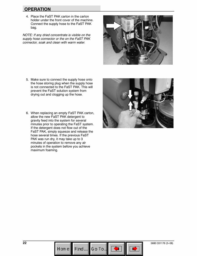
4. Place the FaST PAK carton in the cartonholder under the front cover of the machine.Connect the supply hose to the FaST PAKbag.
NOTE: If any dried concentrate is visible on thesupply hose connector or the on the FaST PAKconnector, soak and clean with warm water.
5. Make sure to connect the supply hose ontothe hose storing plug when the supply hoseis not connected to the FaST PAK. This willprevent the FaST solution system fromdrying out and clogging up the hose.
6. When replacing an empty FaST PAK carton,allow the new FaST PAK detergent togravity feed into the system for severalminutes prior to operating the FaST system.If the detergent does not flow out of theFaST PAK, simply squeeze and release thehose several times. If the previous FaSTPAK was run dry, it may take up to 3minutes of operation to remove any airpockets in the system before you achievemaximum foaming.
OPERATION
235680 331176 (9--06)
STARTING THE MACHINE
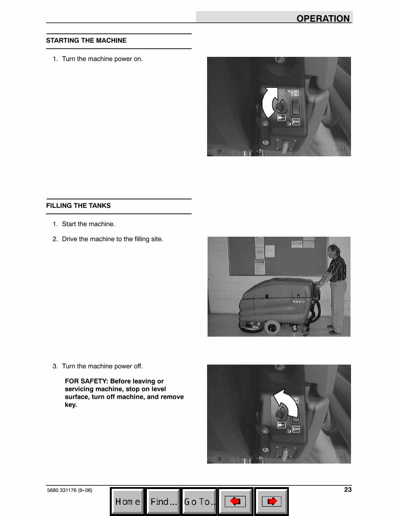
1. Turn the machine power on.
FILLING THE TANKS
1. Start the machine.
2. Drive the machine to the filling site.
3. Turn the machine power off.
FOR SAFETY: Before leaving orservicing machine, stop on levelsurface, turn off machine, and removekey.
OPERATION
5680 331176 (09--08)24
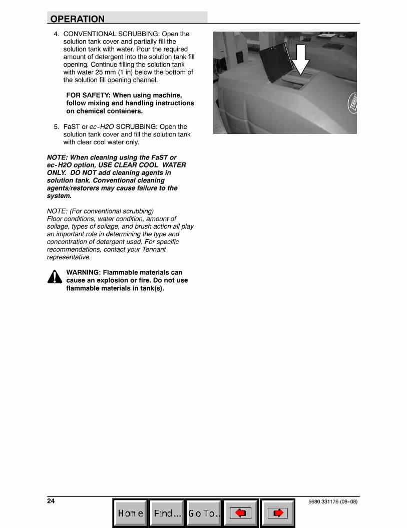
4. CONVENTIONAL SCRUBBING: Open thesolution tank cover and partially fill thesolution tank with water. Pour the requiredamount of detergent into the solution tank fillopening. Continue filling the solution tankwith water 25 mm (1 in) below the bottom ofthe solution fill opening channel.
FOR SAFETY: When using machine,follow mixing and handling instructionson chemical containers.
5. FaST or ec--H2O SCRUBBING: Open thesolution tank cover and fill the solution tankwith clear cool water only.
NOTE: When cleaning using the FaST orec-H2O option, USE CLEAR COOL WATERONLY. DO NOT add cleaning agents insolution tank. Conventional cleaningagents/restorers may cause failure to thesystem.
NOTE: (For conventional scrubbing)Floor conditions, water condition, amount ofsoilage, types of soilage, and brush action all playan important role in determining the type andconcentration of detergent used. For specificrecommendations, contact your Tennantrepresentative.
WARNING: Flammable materials cancause an explosion or fire. Do not useflammable materials in tank(s).
OPERATION
255680 331176 (9--06)
NORMAL SCRUBBING
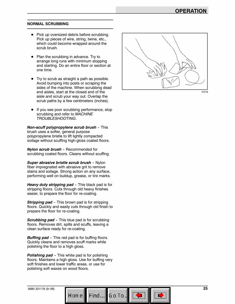
D Pick up oversized debris before scrubbing.Pick up pieces of wire, string, twine, etc.,which could become wrapped around thescrub brush.
D Plan the scrubbing in advance. Try toarrange long runs with minimum stoppingand starting. Do an entire floor or section atone time.
D Try to scrub as straight a path as possible.Avoid bumping into posts or scraping thesides of the machine. When scrubbing deadend aisles, start at the closed end of theaisle and scrub your way out. Overlap thescrub paths by a few centimeters (inches).
D If you see poor scrubbing performance, stopscrubbing and refer to MACHINETROUBLESHOOTING.
Non-scuff polypropylene scrub brush -- Thisbrush uses a softer, general purposepolypropylene bristle to lift lightly compactedsoilage without scuffing high-gloss coated floors.
Nylon scrub brush -- Recommended forscrubbing coated floors. Cleans without scuffing.
Super abrasive bristle scrub brush -- Nylonfiber impregnated with abrasive grit to removestains and soilage. Strong action on any surface,performing well on buildup, grease, or tire marks.
Heavy duty stripping pad -- This black pad is forstripping floors. Cuts through old heavy finisheseasier, to prepare the floor for re-coating.
Stripping pad -- This brown pad is for strippingfloors. Quickly and easily cuts through old finish toprepare the floor for re-coating.
Scrubbing pad -- This blue pad is for scrubbingfloors. Removes dirt, spills and scuffs, leaving aclean surface ready for re-coating.
Buffing pad -- This red pad is for buffing floors.Quickly cleans and removes scuff marks whilepolishing the floor to a high gloss.
Polishing pad -- This white pad is for polishingfloors. Maintains a high gloss. Use for buffing verysoft finishes and lower traffic areas, or use forpolishing soft waxes on wood floors.
07218
OPERATION
5680 331176 (9--06)26
Cylindrical polypropylene scrub brush -- Thiscylindrical brush uses a softer, general purposepolypropylene bristle to lift lightly compactedsoilage without scuffing high-gloss coated floors.
Cylindrical nylon scrub brush -- This cylindricalbrush is recommended for scrubbing coatedfloors. Cleans without scuffing.
Cylindrical super abrasive bristle scrub brush-- Nylon fiber impregnated with abrasive grit toremove stains and soilage. Strong action on anysurface, performing well on buildup, grease, or tiremarks.
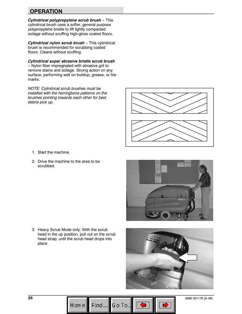
NOTE: Cylindrical scrub brushes must beinstalled with the herringbone patterns on thebrushes pointing towards each other for bestdebris pick up.
1. Start the machine.
2. Drive the machine to the area to bescrubbed.
3. Heavy Scrub Mode only: With the scrubhead in the up position, pull out on the scrubhead strap, until the scrub head drops intoplace.
OPERATION
275680 331176 (09--08)
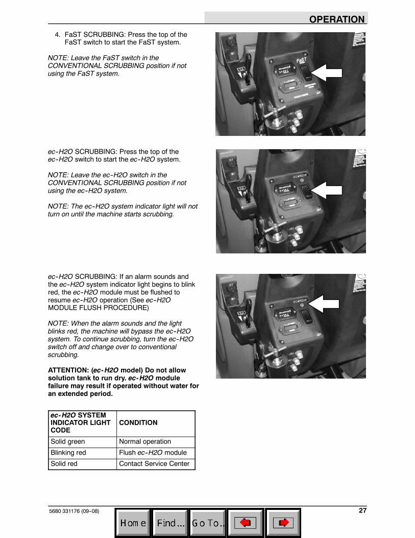
4. FaST SCRUBBING: Press the top of theFaST switch to start the FaST system.
NOTE: Leave the FaST switch in theCONVENTIONAL SCRUBBING position if notusing the FaST system.
ec--H2O SCRUBBING: Press the top of theec--H2O switch to start the ec--H2O system.
NOTE: Leave the ec--H2O switch in theCONVENTIONAL SCRUBBING position if notusing the ec--H2O system.
NOTE: The ec--H2O system indicator light will notturn on until the machine starts scrubbing.
ec--H2O SCRUBBING: If an alarm sounds andthe ec--H2O system indicator light begins to blinkred, the ec--H2O module must be flushed toresume ec--H2O operation (See ec--H2OMODULE FLUSH PROCEDURE)
NOTE: When the alarm sounds and the lightblinks red, the machine will bypass the ec--H2Osystem. To continue scrubbing, turn the ec--H2Oswitch off and change over to conventionalscrubbing.
ATTENTION: (ec-H2O model) Do not allowsolution tank to run dry. ec-H2O modulefailure may result if operated without water foran extended period.
ec-H2O SYSTEMINDICATOR LIGHTCODE
CONDITION
Solid green Normal operation
Blinking red Flush ec--H2O module
Solid red Contact Service Center
OPERATION
5680 331176 (09--08)28
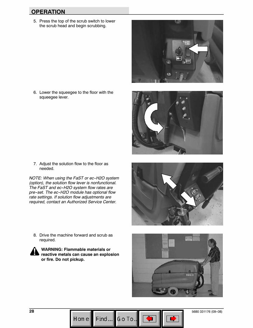
5. Press the top of the scrub switch to lowerthe scrub head and begin scrubbing.
6. Lower the squeegee to the floor with thesqueegee lever.
7. Adjust the solution flow to the floor asneeded.
NOTE: When using the FaST or ec--H2O system(option), the solution flow lever is nonfunctional.The FaST and ec--H2O system flow rates arepre--set. The ec--H2O module has optional flowrate settings. If solution flow adjustments arerequired, contact an Authorized Service Center.
8. Drive the machine forward and scrub asrequired.
WARNING: Flammable materials orreactive metals can cause an explosionor fire. Do not pickup.
OPERATION
295680 331176 (09--08)
DOUBLE SCRUBBING
Double scrubbing is a method for removing heavyfloor accumulations. This is done by making twopasses over the area to be cleaned with themachine.
Double scrubbing can be performed using theFaST SCRUBBING SYSTEM (option),ec--H2O SCRUBBING SYSTEM (option) orCONVENTIONAL SCRUBBING methods.
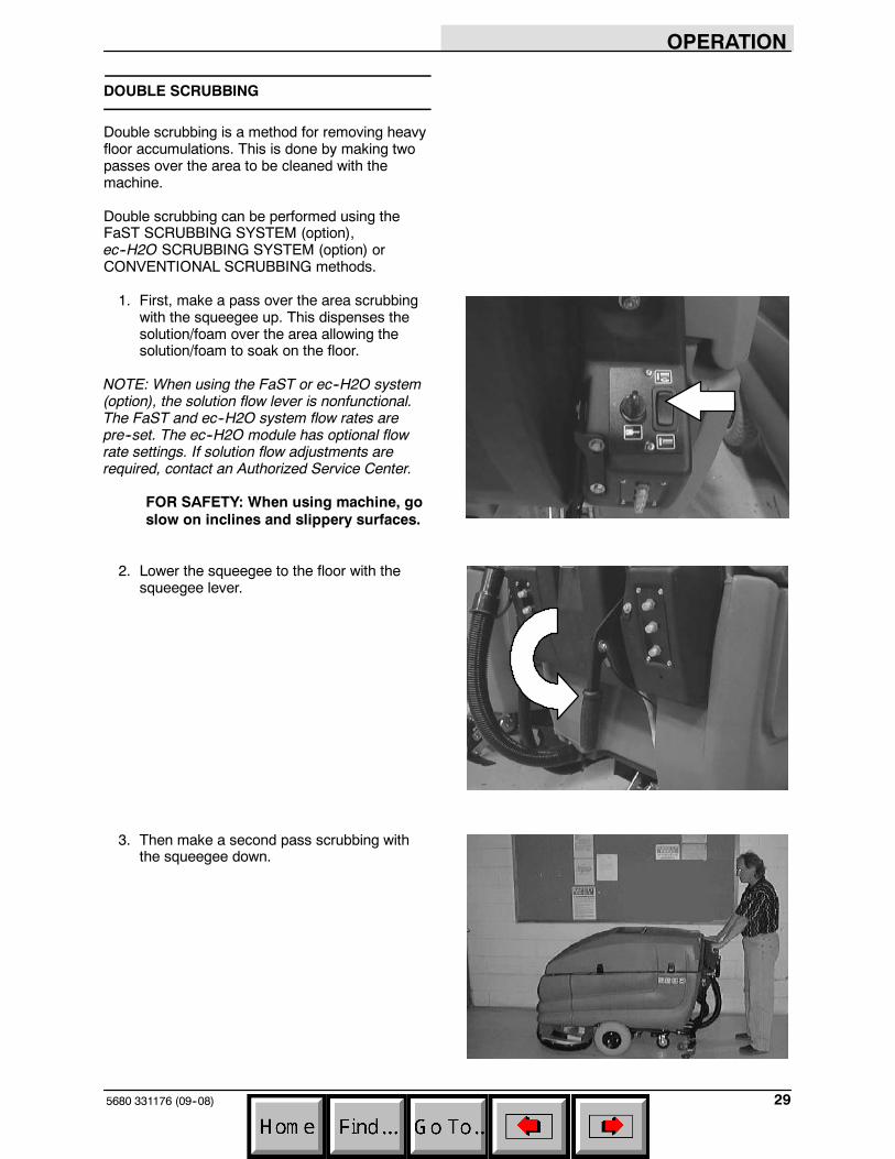
1. First, make a pass over the area scrubbingwith the squeegee up. This dispenses thesolution/foam over the area allowing thesolution/foam to soak on the floor.
NOTE: When using the FaST or ec--H2O system(option), the solution flow lever is nonfunctional.The FaST and ec--H2O system flow rates arepre--set. The ec--H2O module has optional flowrate settings. If solution flow adjustments arerequired, contact an Authorized Service Center.
FOR SAFETY: When using machine, goslow on inclines and slippery surfaces.
2. Lower the squeegee to the floor with thesqueegee lever.
3. Then make a second pass scrubbing withthe squeegee down.
OPERATION
5680 331176 (9--06)30
STOP SCRUBBING
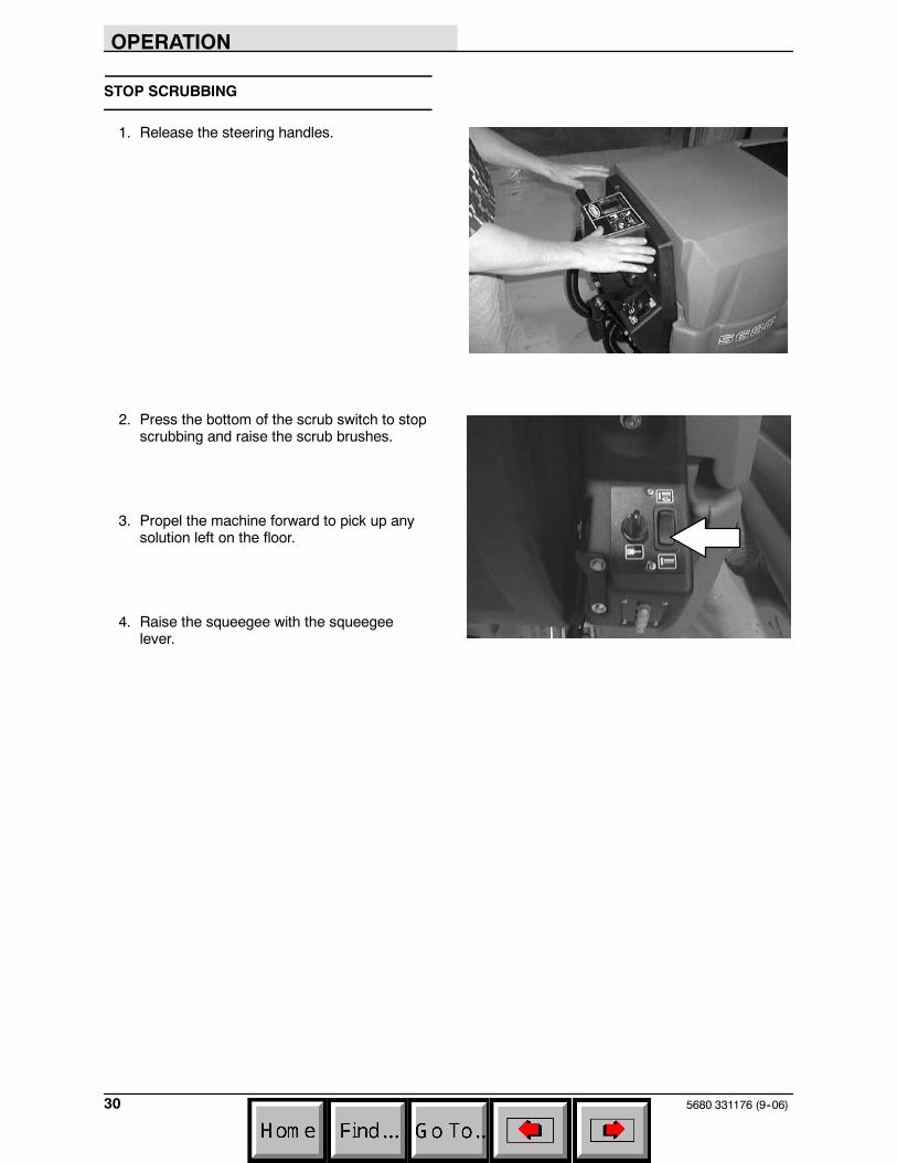
1. Release the steering handles.
2. Press the bottom of the scrub switch to stopscrubbing and raise the scrub brushes.
3. Propel the machine forward to pick up anysolution left on the floor.
4. Raise the squeegee with the squeegeelever.
OPERATION
315680 331176 (9--06)
DRAINING AND CLEANING THE TANKS
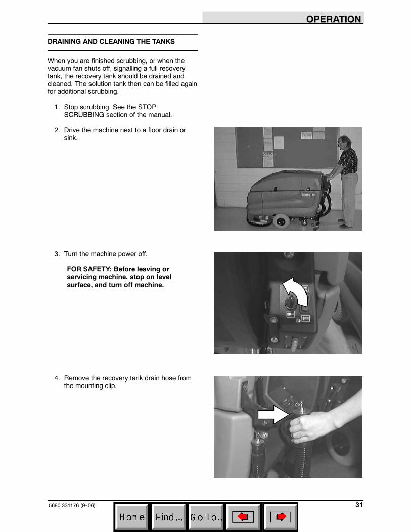
When you are finished scrubbing, or when thevacuum fan shuts off, signalling a full recoverytank, the recovery tank should be drained andcleaned. The solution tank then can be filled againfor additional scrubbing.
1. Stop scrubbing. See the STOPSCRUBBING section of the manual.
2. Drive the machine next to a floor drain orsink.
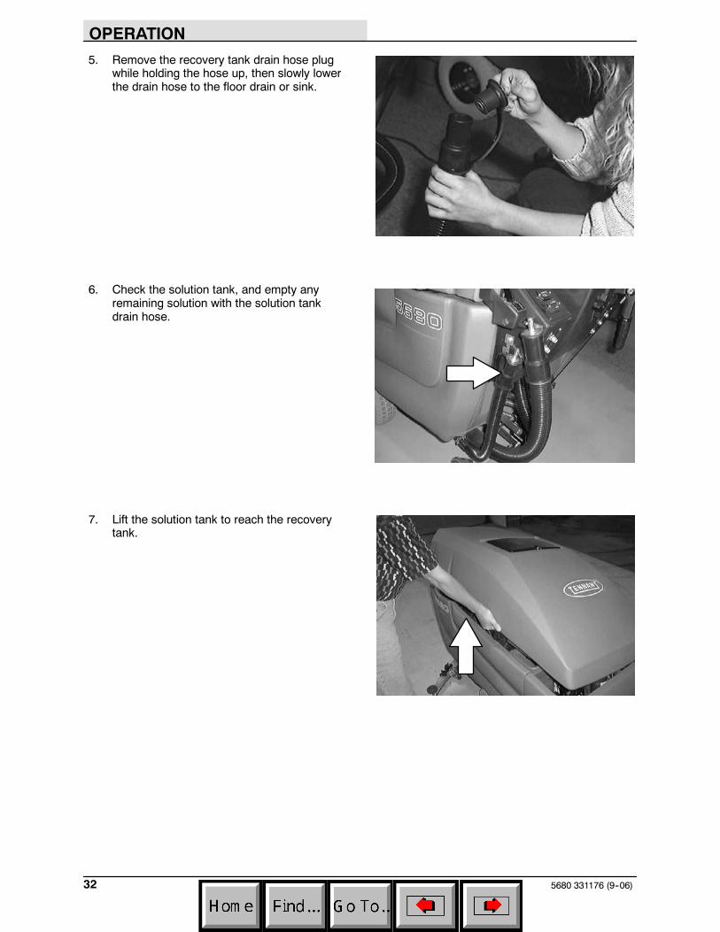
3. Turn the machine power off.
FOR SAFETY: Before leaving orservicing machine, stop on levelsurface, and turn off machine.
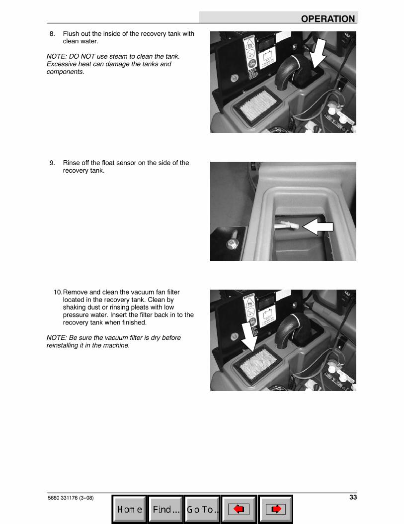
4. Remove the recovery tank drain hose fromthe mounting clip.
OPERATION
5680 331176 (9--06)32
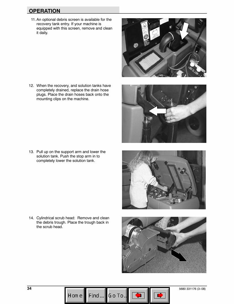
5. Remove the recovery tank drain hose plugwhile holding the hose up, then slowly lowerthe drain hose to the floor drain or sink.
6. Check the solution tank, and empty anyremaining solution with the solution tankdrain hose.
7. Lift the solution tank to reach the recoverytank.
OPERATION
335680 331176 (3--08)
8. Flush out the inside of the recovery tank withclean water.
NOTE: DO NOT use steam to clean the tank.Excessive heat can damage the tanks andcomponents.
9. Rinse off the float sensor on the side of therecovery tank.
10.Remove and clean the vacuum fan filterlocated in the recovery tank. Clean byshaking dust or rinsing pleats with lowpressure water. Insert the filter back in to therecovery tank when finished.
NOTE: Be sure the vacuum filter is dry beforereinstalling it in the machine.
OPERATION
5680 331176 (3--08)34
11.An optional debris screen is available for therecovery tank entry. If your machine isequipped with this screen, remove and cleanit daily.
12. When the recovery, and solution tanks havecompletely drained, replace the drain hoseplugs. Place the drain hoses back onto themounting clips on the machine.
13. Pull up on the support arm and lower thesolution tank. Push the stop arm in tocompletely lower the solution tank.
14. Cylindrical scrub head: Remove and cleanthe debris trough. Place the trough back inthe scrub head.
OPERATION
355680 331176 (9--06)
OPERATION ON INCLINES
Drive the machine slowly on inclines.
FOR SAFETY: When using machine, goslow on inclines and slippery surfaces.
The maximum rated climb and descent inclinewith empty tanks is 8_, with full tanks is 6_.
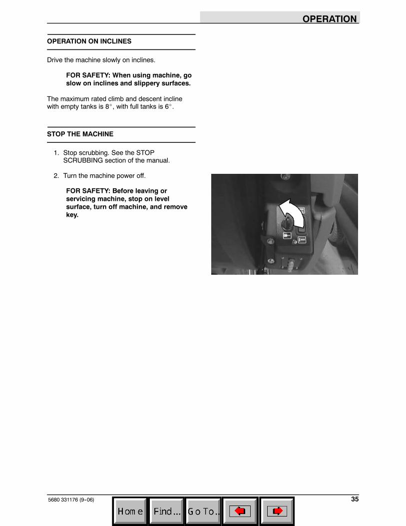
STOP THE MACHINE
1. Stop scrubbing. See the STOPSCRUBBING section of the manual.
2. Turn the machine power off.
FOR SAFETY: Before leaving orservicing machine, stop on levelsurface, turn off machine, and removekey.
OPERATION
5680 331176 (9--06)36
POST-OPERATION CHECKLIST
Check over this list of items after you havefinished scrubbing with the machine powered on:
- Check the battery charge level.
NOTE: The reading on the battery dischargeindicator may not be accurate when the machineis first powered on. Operate the machine a fewminutes before reading the charge level of thebatteries.
Check over this list of items with the machinepowered off:
- Check for wire, string, or twine wrappedaround the scrub brushes.
- Check the squeegees for wear or damage.
- Check the squeegee suction hose forobstructions.
- Drain and clean the recovery tank.
- Clean the vacuum fan inlet filter.
- Check under the machine for leaks.
- Check the service records to determinemaintenance requirements.
- FaST scrubbing: If FaST PAK is empty afterscrubbing, install the new FaST PAK orconnect the supply hose to the storage plug.
OPERATION
375680 331176 (3--08)
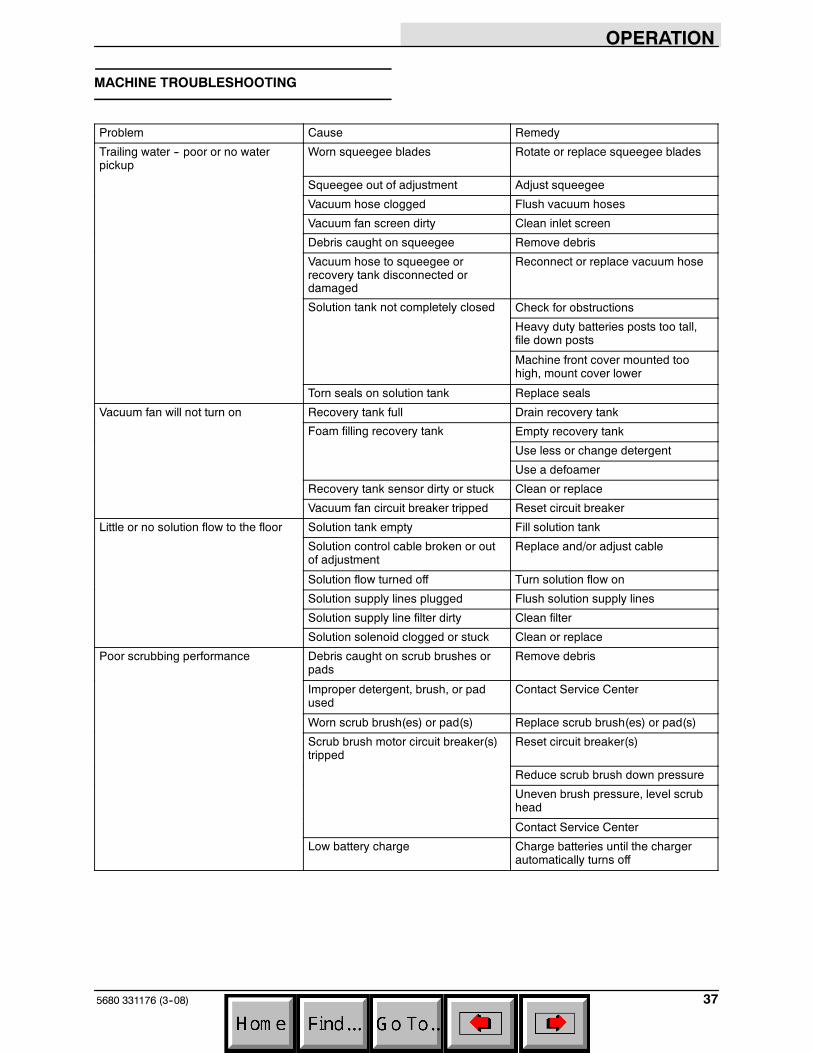
MACHINE TROUBLESHOOTING
Problem Cause Remedy
Trailing water -- poor or no waterpickup
Worn squeegee blades Rotate or replace squeegee blades
Squeegee out of adjustment Adjust squeegee
Vacuum hose clogged Flush vacuum hoses
Vacuum fan screen dirty Clean inlet screen
Debris caught on squeegee Remove debris
Vacuum hose to squeegee orrecovery tank disconnected ordamaged
Reconnect or replace vacuum hose
Solution tank not completely closed Check for obstructions
Heavy duty batteries posts too tall,file down posts
Machine front cover mounted toohigh, mount cover lower
Torn seals on solution tank Replace seals
Vacuum fan will not turn on Recovery tank full Drain recovery tank
Foam filling recovery tank Empty recovery tank
Use less or change detergent
Use a defoamer
Recovery tank sensor dirty or stuck Clean or replace
Vacuum fan circuit breaker tripped Reset circuit breaker
Little or no solution flow to the floor Solution tank empty Fill solution tank
Solution control cable broken or outof adjustment
Replace and/or adjust cable
Solution flow turned off Turn solution flow on
Solution supply lines plugged Flush solution supply lines
Solution supply line filter dirty Clean filter
Solution solenoid clogged or stuck Clean or replace
Poor scrubbing performance Debris caught on scrub brushes orpads
Remove debris
Improper detergent, brush, or padused
Contact Service Center
Worn scrub brush(es) or pad(s) Replace scrub brush(es) or pad(s)
Scrub brush motor circuit breaker(s)tripped
Reset circuit breaker(s)
Reduce scrub brush down pressure
Uneven brush pressure, level scrubhead
Contact Service Center
Low battery charge Charge batteries until the chargerautomatically turns off
r1l
Line
r1l
Line
r1l
Line
r1l
Line
r1l
Text Box
filter
OPERATION
5680 331176 (09--08)38
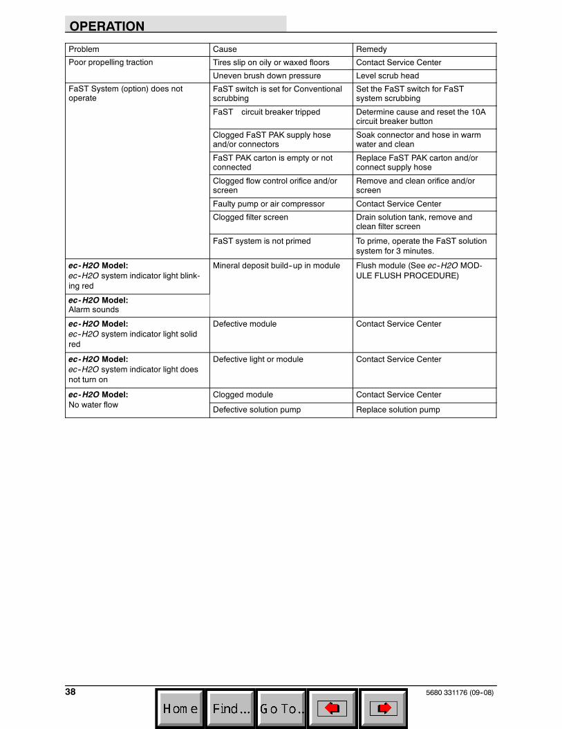
Problem Cause Remedy
Poor propelling traction Tires slip on oily or waxed floors Contact Service Center
Uneven brush down pressure Level scrub head
FaST System (option) does notoperate
FaST switch is set for Conventionalscrubbing
Set the FaST switch for FaSTsystem scrubbing
FaST circuit breaker tripped Determine cause and reset the 10Acircuit breaker button
Clogged FaST PAK supply hoseand/or connectors
Soak connector and hose in warmwater and clean
FaST PAK carton is empty or notconnected
Replace FaST PAK carton and/orconnect supply hose
Clogged flow control orifice and/orscreen
Remove and clean orifice and/orscreen
Faulty pump or air compressor Contact Service Center
Clogged filter screen Drain solution tank, remove andclean filter screen
FaST system is not primed To prime, operate the FaST solutionsystem for 3 minutes.
ec-H2O Model:ec--H2O system indicator light blink-ing red
Mineral deposit build--up in module Flush module (See ec--H2O MOD-ULE FLUSH PROCEDURE)
ec-H2O Model:Alarm sounds
ec-H2O Model:ec--H2O system indicator light solidred
Defective module Contact Service Center
ec-H2O Model:ec--H2O system indicator light doesnot turn on
Defective light or module Contact Service Center
ec-H2O Model:No water flow
Clogged module Contact Service Center
Defective solution pump Replace solution pump
MAINTENANCE
395680 331176 (3--08)
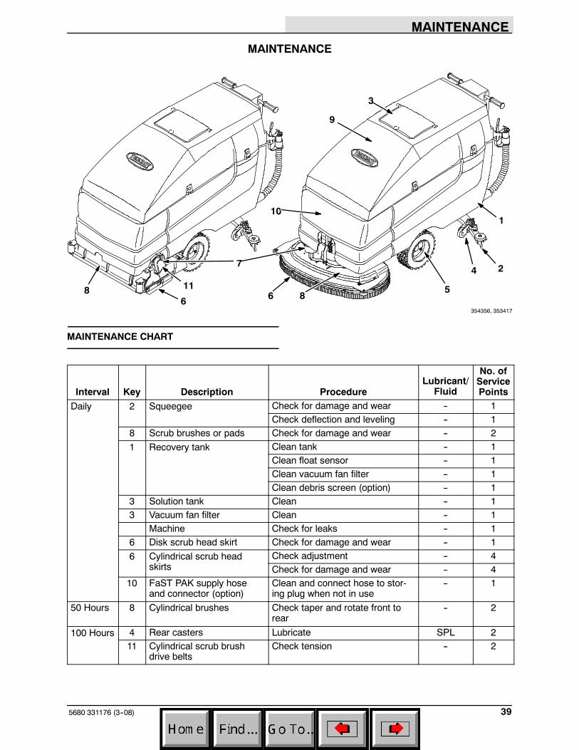
MAINTENANCE
1
2
3
4
56
7
8
9
10
11
68
354356, 353417
MAINTENANCE CHART
Interval Key Description ProcedureLubricant/
Fluid
No. ofServicePoints
Daily 2 Squeegee Check for damage and wear -- 1Check deflection and leveling -- 1
8 Scrub brushes or pads Check for damage and wear -- 2
1 Recovery tank Clean tank -- 1Clean float sensor -- 1Clean vacuum fan filter -- 1Clean debris screen (option) -- 1
3 Solution tank Clean -- 13 Vacuum fan filter Clean -- 1
Machine Check for leaks -- 16 Disk scrub head skirt Check for damage and wear -- 1
6 Cylindrical scrub headskirts
Check adjustment -- 4Check for damage and wear -- 4
10 FaST PAK supply hoseand connector (option)
Clean and connect hose to stor-ing plug when not in use
-- 1
50 Hours 8 Cylindrical brushes Check taper and rotate front torear
-- 2
100 Hours 4 Rear casters Lubricate SPL 211 Cylindrical scrub brush
drive beltsCheck tension -- 2
MAINTENANCE
5680 331176 (3--08)40
Interval Key Description ProcedureLubricant/
Fluid
No. ofServicePoints
500 Hours 9 Vacuum fan motor Check motor brushes -- 1
1000Hours
10 FaST water and air filters(option)
Replace -- 1
7 Scrub brush motors Check motor brushes -- 25 Propelling motor Check motor brushes -- 15 Transaxle Check lubricant level GL 1
SPL -- Special lubricant, Lubriplate EMB grease (TENNANT part no. 01433--1)GL -- SAE 90 weight gear lubricant
MAINTENANCE
415680 331176 (9--06)
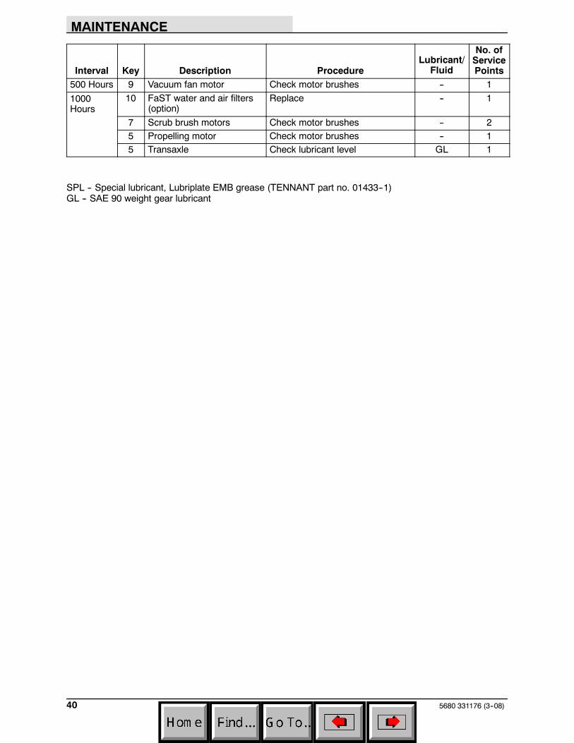
LUBRICATION
REAR CASTERS
The rear casters each have one grease fitting onthe caster swivel. Lubricate the caster with agrease gun containing Lubriplate EMB grease(TENNANT part no. 01433--1) every 100 hours ofmachine operation.
TRANSAXLE
Check the transaxle lubricant level every 1000hours of operation by removing one of the orangefiller plugs. If needed, add SAE 90 weight gearlubricant.
BATTERIES
The batteries are unique in that they hold theirpower for long periods of time. The lifetime of thebatteries is limited by the number of charges thebatteries receive. To get the most life from thebatteries, charge them when all the batterydischarge indicator segments shut off (20%charge left). Use an automatic charger with theproper rating for the batteries.
Periodically clean the top surface of the batteriesand the terminals, and check for looseconnections. Use a strong solution of baking sodaand water. Brush the solution sparingly over thebattery tops, terminals, and cable clamps. Do notallow any baking soda solution to enter thebatteries. Use a wire brush to clean the terminalposts and the cable connectors. After cleaning,apply a coating of clear battery post protectant tothe terminals and the cable connectors. Keep thetops of the batteries clean and dry.
MAINTENANCE
5680 331176 (9--06)42
Keep all metallic objects off the top of thebatteries, which may cause a short circuit.Replace any worn or damaged wires.
Never add acid to the batteries, only distilledwater. Always keep the battery caps on, exceptwhen adding water or taking hydrometer readings.
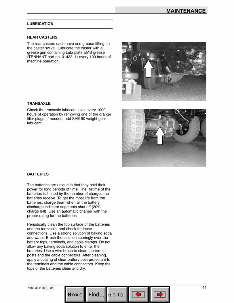
Check the electrolyte level in each battery cellbefore and after charging, and after every 50hours of operation. Do not charge the batteriesunless the fluid is slightly above the battery plates.If needed, add just enough distilled water to coverthe plates. Never add acid to the batteries. Do notoverfill. Always keep the battery caps on, exceptwhen adding water or taking hydrometer readings.
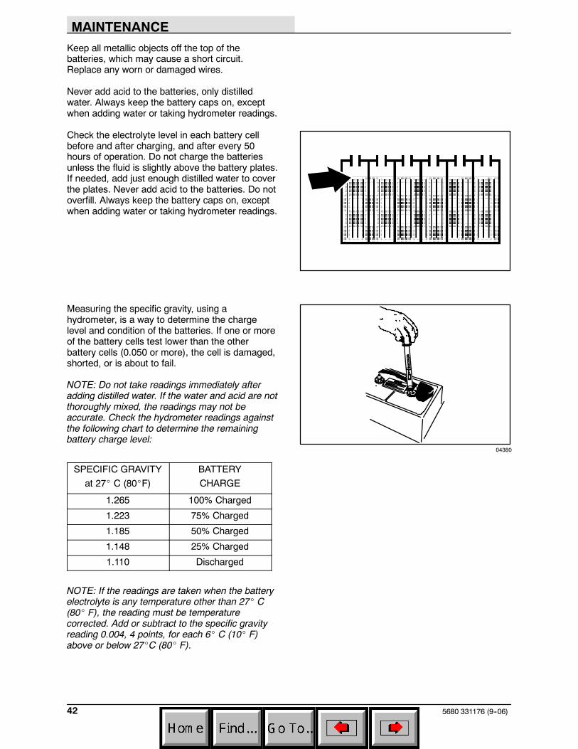
Measuring the specific gravity, using ahydrometer, is a way to determine the chargelevel and condition of the batteries. If one or moreof the battery cells test lower than the otherbattery cells (0.050 or more), the cell is damaged,shorted, or is about to fail.
NOTE: Do not take readings immediately afteradding distilled water. If the water and acid are notthoroughly mixed, the readings may not beaccurate. Check the hydrometer readings againstthe following chart to determine the remainingbattery charge level:
SPECIFIC GRAVITY
at 27_ C (80_F)
BATTERY
CHARGE
1.265 100% Charged
1.223 75% Charged
1.185 50% Charged
1.148 25% Charged
1.110 Discharged
NOTE: If the readings are taken when the batteryelectrolyte is any temperature other than 27_ C(80_ F), the reading must be temperaturecorrected. Add or subtract to the specific gravityreading 0.004, 4 points, for each 6_ C (10_ F)above or below 27_C (80_ F).
04380
MAINTENANCE
435680 331176 (9--06)
CHARGING THE BATTERIES
1. Drive the machine to a flat, dry surface in awell-ventilated area.
2. Turn the machine power off and set theparking brake if your machine has thisoption.
FOR SAFETY: Before leaving orservicing machine, stop on levelsurface, and turn off machine.
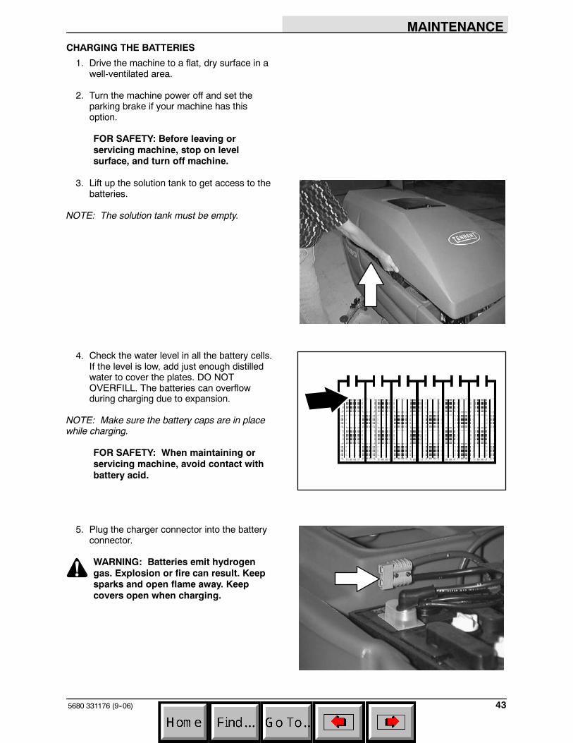
3. Lift up the solution tank to get access to thebatteries.
NOTE: The solution tank must be empty.
4. Check the water level in all the battery cells.If the level is low, add just enough distilledwater to cover the plates. DO NOTOVERFILL. The batteries can overflowduring charging due to expansion.
NOTE: Make sure the battery caps are in placewhile charging.
FOR SAFETY: When maintaining orservicing machine, avoid contact withbattery acid.
5. Plug the charger connector into the batteryconnector.
WARNING: Batteries emit hydrogengas. Explosion or fire can result. Keepsparks and open flame away. Keepcovers open when charging.
MAINTENANCE
5680 331176 (9--06)44
6. Plug the battery charger into the wall outlet.
NOTE: If the red “ABNORMAL CYCLE” lamplights when the TENNANT charger is plugged intoa wall outlet, the charger cannot charge thebattery and there is something wrong with thebattery.
7. The TENNANT charger will startautomatically. When the batteries are fullycharged, the TENNANT charger willautomatically turn off.
8. After the charger has turned off, unplug thecharger from the wall outlet.
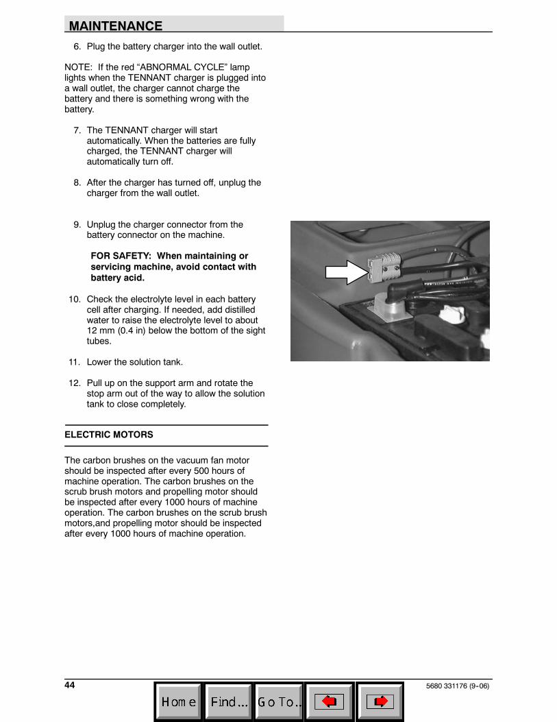
9. Unplug the charger connector from thebattery connector on the machine.
FOR SAFETY: When maintaining orservicing machine, avoid contact withbattery acid.
10. Check the electrolyte level in each batterycell after charging. If needed, add distilledwater to raise the electrolyte level to about12 mm (0.4 in) below the bottom of the sighttubes.
11. Lower the solution tank.
12. Pull up on the support arm and rotate thestop arm out of the way to allow the solutiontank to close completely.
ELECTRIC MOTORS
The carbon brushes on the vacuum fan motorshould be inspected after every 500 hours ofmachine operation. The carbon brushes on thescrub brush motors and propelling motor shouldbe inspected after every 1000 hours of machineoperation. The carbon brushes on the scrub brushmotors,and propelling motor should be inspectedafter every 1000 hours of machine operation.
MAINTENANCE
455680 331176 (9--06)
SCRUB HEAD
The machine is equipped with a disk brush scrubhead. The scrub head contains skirts to controlover-spray from the scrub brushes.
DISK BRUSH SCRUB HEAD SKIRT
Make sure the scrub head skirt touches the floorall the way around when the scrub head islowered. Check the skirt for damage or wear daily.
NOTE: Replace the scrub head skirt when it isdamaged or no longer is able to touch the floor.
CYLINDRICAL BRUSH SCRUB HEAD SKIRTS
The four head skirts should just touch the floor.Check the skirts for damage or wear daily.
ADJUSTING THE SCRUB HEAD SKIRTS
1. Lower the scrub head on a level floor.
2. Turn the machine power off.
FOR SAFETY: Before leaving orservicing machine, stop on levelsurface, and turn off machine.
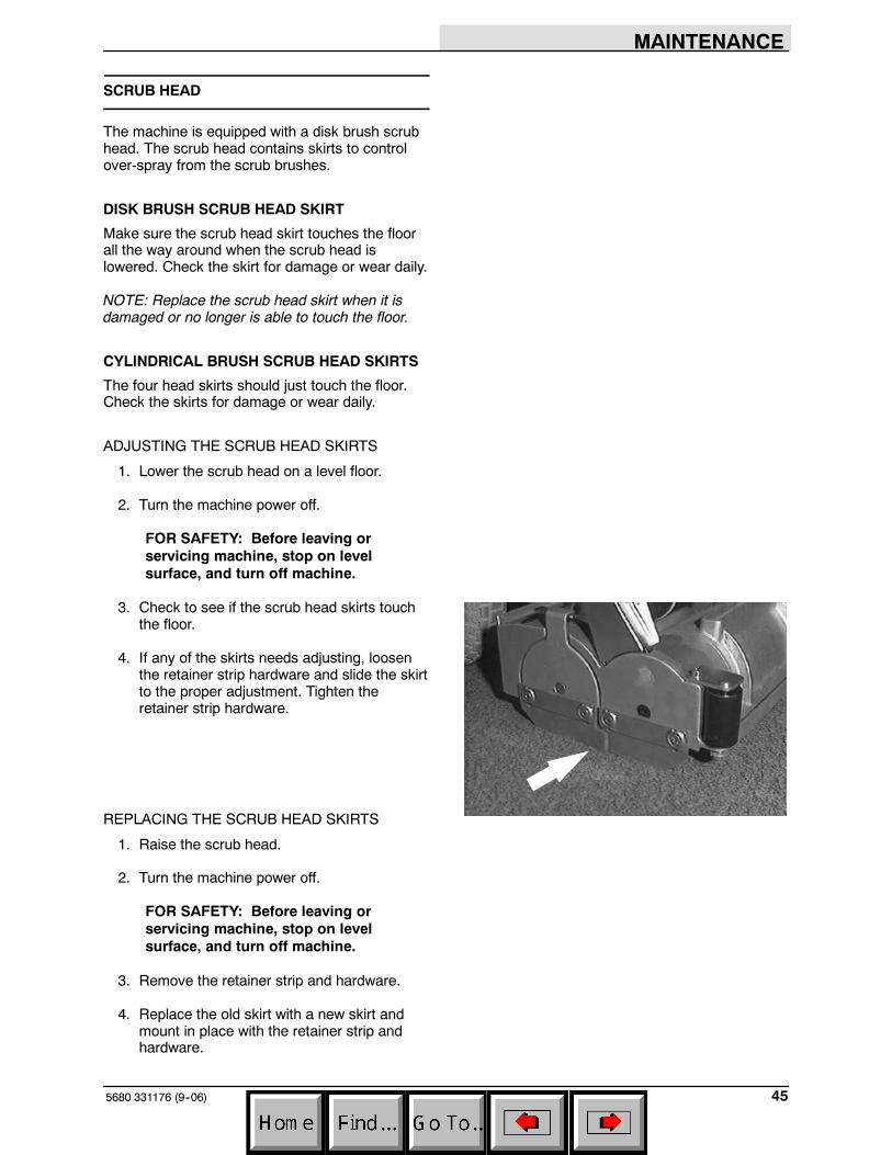
3. Check to see if the scrub head skirts touchthe floor.
4. If any of the skirts needs adjusting, loosenthe retainer strip hardware and slide the skirtto the proper adjustment. Tighten theretainer strip hardware.
REPLACING THE SCRUB HEAD SKIRTS
1. Raise the scrub head.
2. Turn the machine power off.
FOR SAFETY: Before leaving orservicing machine, stop on levelsurface, and turn off machine.
3. Remove the retainer strip and hardware.
4. Replace the old skirt with a new skirt andmount in place with the retainer strip andhardware.
MAINTENANCE
5680 331176 (9--06)46
REMOVING OR REPLACING THE SCRUBHEAD
The scrub heads are available in three widths.
NOTE: When you change to a different widthscrub head, be sure to install the appropriatewidth squeegee and machine front cover.
1. Lower the scrub head.
2. Turn the machine power off.
FOR SAFETY: Before leaving orservicing machine, stop on levelsurface, and turn off machine.
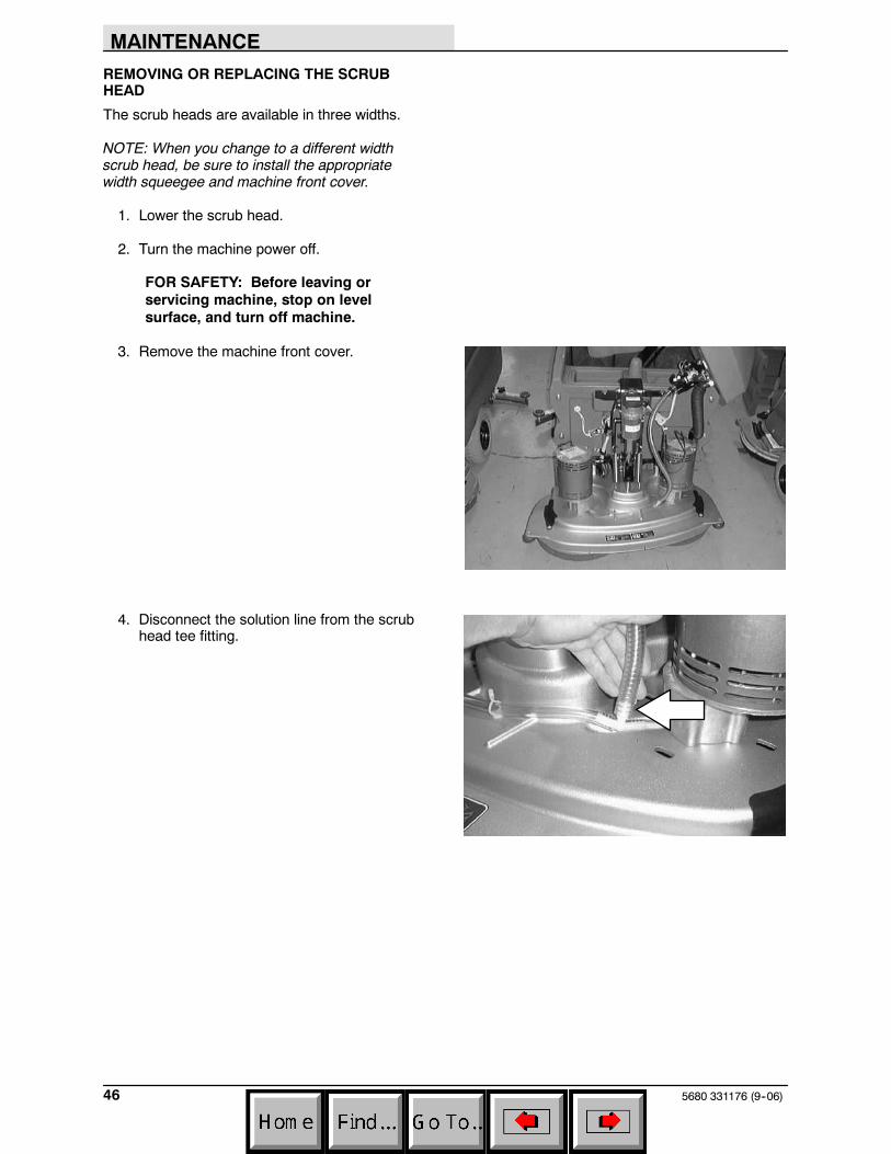
3. Remove the machine front cover.
4. Disconnect the solution line from the scrubhead tee fitting.
MAINTENANCE
475680 331176 (9--06)
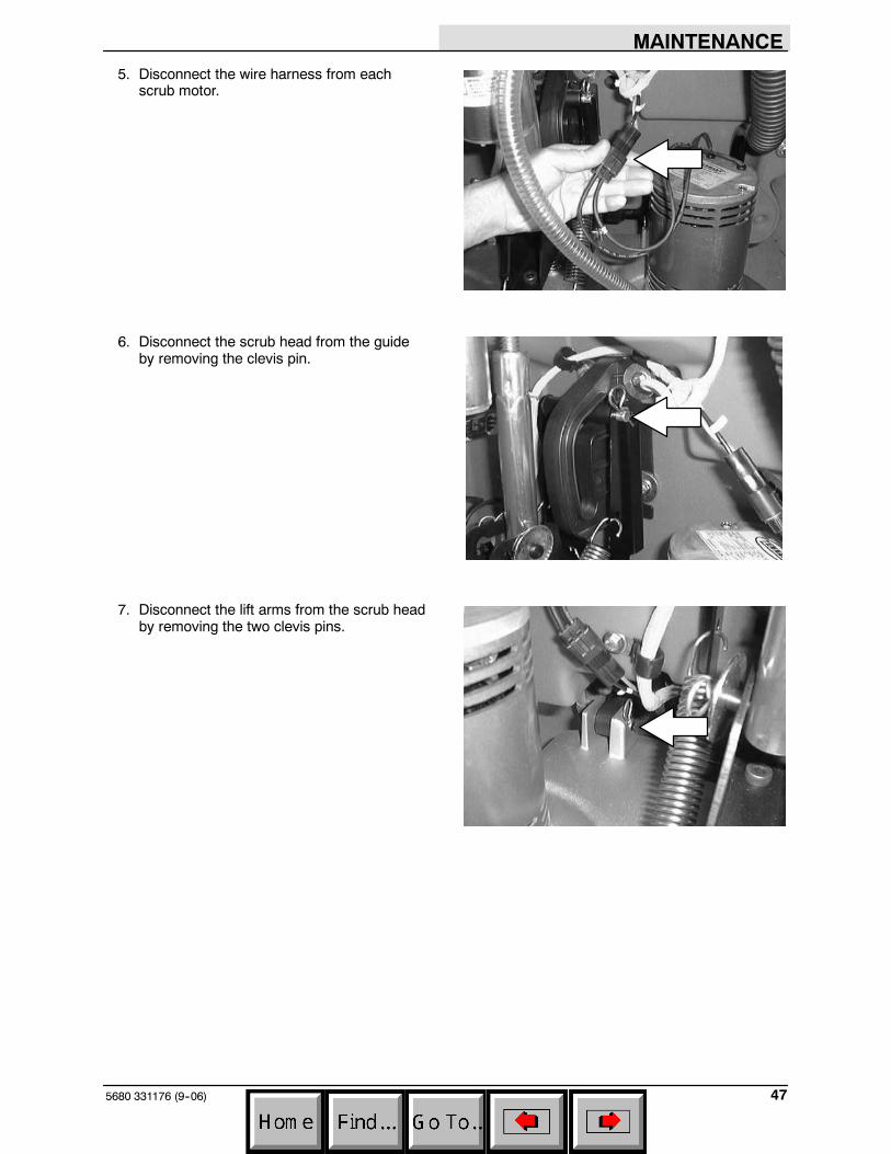
5. Disconnect the wire harness from eachscrub motor.
6. Disconnect the scrub head from the guideby removing the clevis pin.
7. Disconnect the lift arms from the scrub headby removing the two clevis pins.
MAINTENANCE
5680 331176 (9--06)48
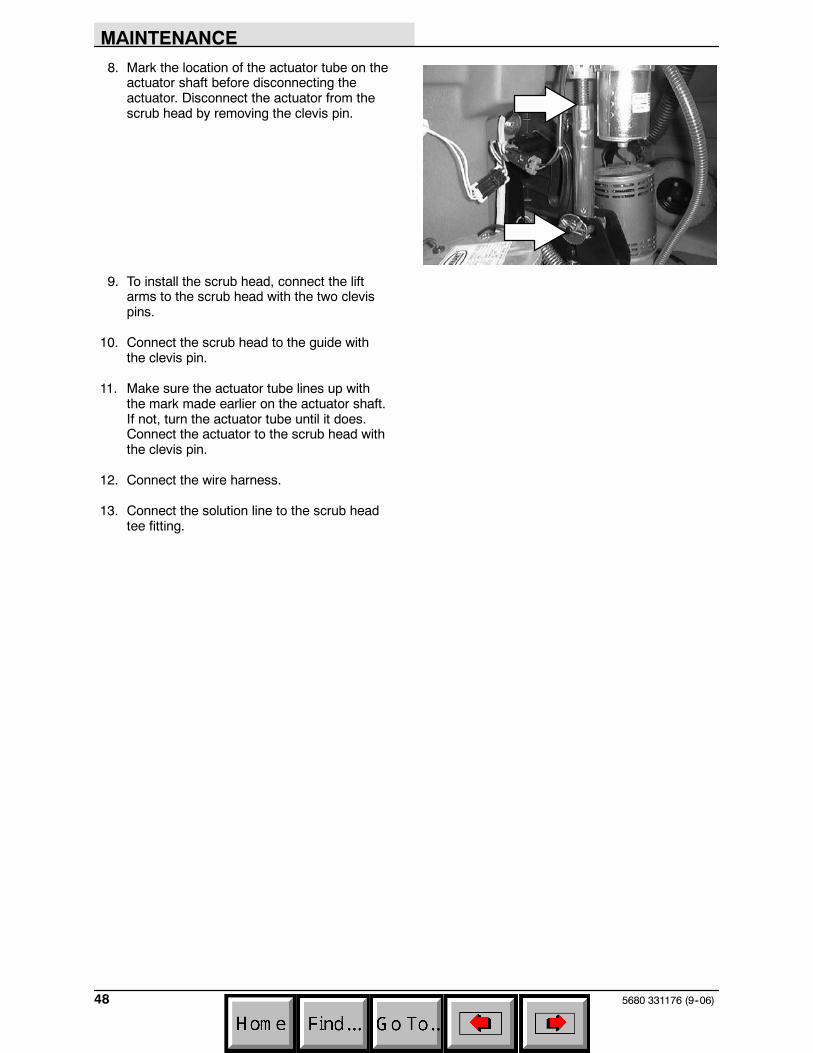
8. Mark the location of the actuator tube on theactuator shaft before disconnecting theactuator. Disconnect the actuator from thescrub head by removing the clevis pin.
9. To install the scrub head, connect the liftarms to the scrub head with the two clevispins.
10. Connect the scrub head to the guide withthe clevis pin.
11. Make sure the actuator tube lines up withthe mark made earlier on the actuator shaft.If not, turn the actuator tube until it does.Connect the actuator to the scrub head withthe clevis pin.
12. Connect the wire harness.
13. Connect the solution line to the scrub headtee fitting.
MAINTENANCE
495680 331176 (9--06)
LEVELING THE SCRUB HEAD
1. Make sure the scrub head is lowered to thefloor.
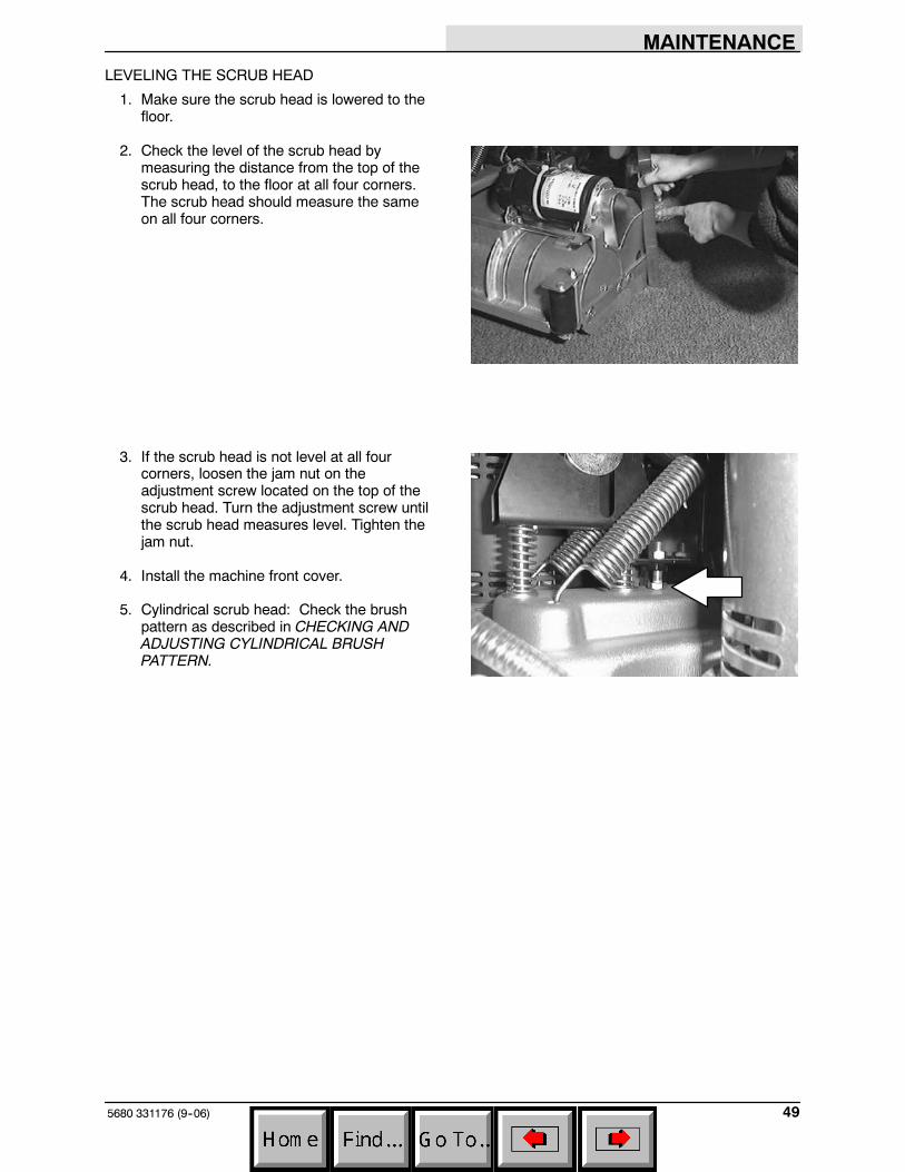
2. Check the level of the scrub head bymeasuring the distance from the top of thescrub head, to the floor at all four corners.The scrub head should measure the sameon all four corners.
3. If the scrub head is not level at all fourcorners, loosen the jam nut on theadjustment screw located on the top of thescrub head. Turn the adjustment screw untilthe scrub head measures level. Tighten thejam nut.
4. Install the machine front cover.
5. Cylindrical scrub head: Check the brushpattern as described in CHECKING ANDADJUSTING CYLINDRICAL BRUSHPATTERN.
MAINTENANCE
5680 331176 (9--06)50
SCRUB BRUSHES AND PADS
The scrub brushes should be checked daily forwire or string tangled around the brush or drivehub. The brushes should also be checked for anydamage and wear.
DISK BRUSHES
The disk brushes should be replaced if largeamounts of bristles are missing, or if theremaining bristles’ length is less than 10 mm(0.38 in).
Cleaning pads must be placed on pad drivesbefore they are ready to use. The cleaning pad isheld in place by a pad holder.
Cleaning pads need to be cleaned immediatelyafter using with soap and water. Do not wash thepads with a pressure washer. Hang dry pads, orlie flat to dry.
NOTE: Be sure to replace brushes and pads insets. Otherwise one brush or pad will be moreaggressive than the other.
REPLACING THE DISK BRUSHES OR PADS
1. Raise the scrub head.
2. Turn the machine power off.
FOR SAFETY: Before leaving orservicing machine, stop on levelsurface, and turn off machine.
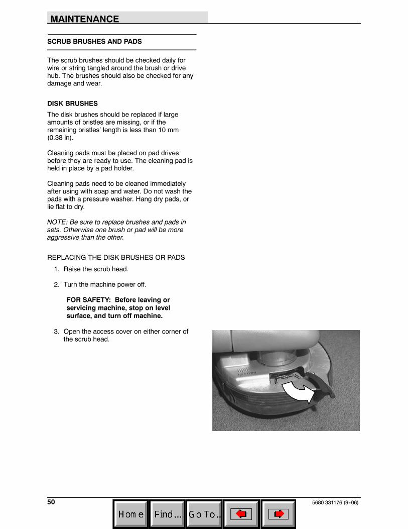
3. Open the access cover on either corner ofthe scrub head.
MAINTENANCE
515680 331176 (9--06)
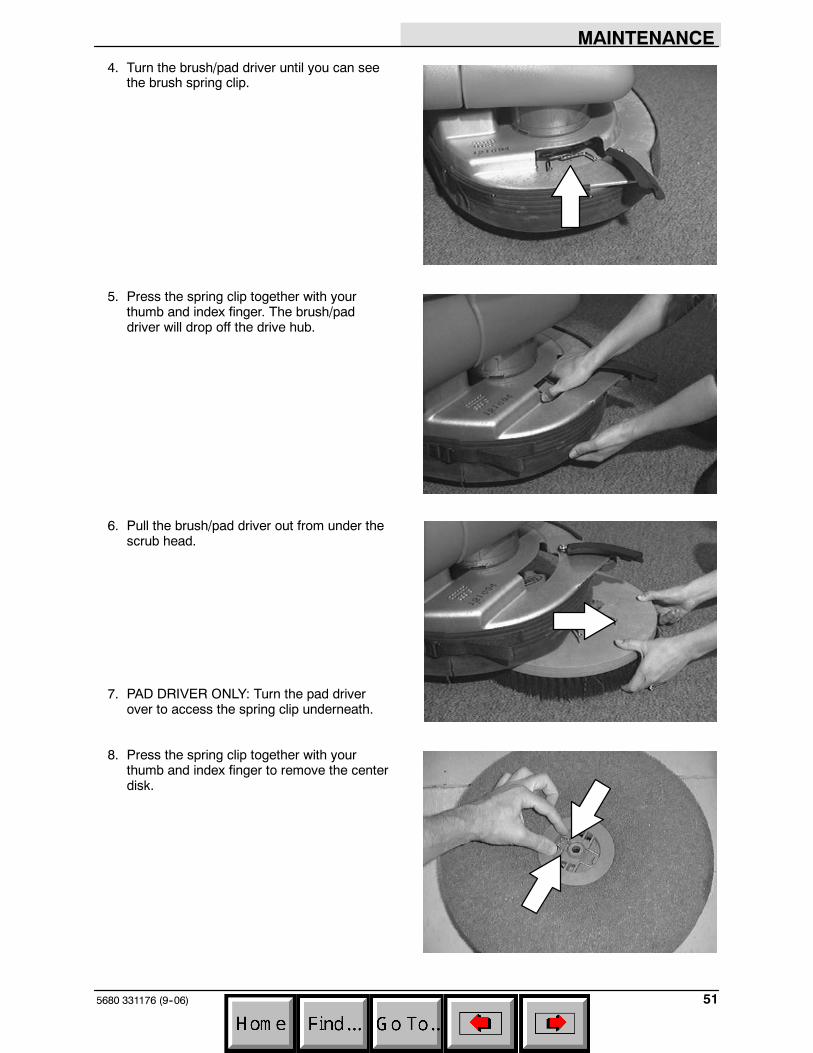
4. Turn the brush/pad driver until you can seethe brush spring clip.
5. Press the spring clip together with yourthumb and index finger. The brush/paddriver will drop off the drive hub.
6. Pull the brush/pad driver out from under thescrub head.
7. PAD DRIVER ONLY: Turn the pad driverover to access the spring clip underneath.
8. Press the spring clip together with yourthumb and index finger to remove the centerdisk.
MAINTENANCE
5680 331176 (9--06)52
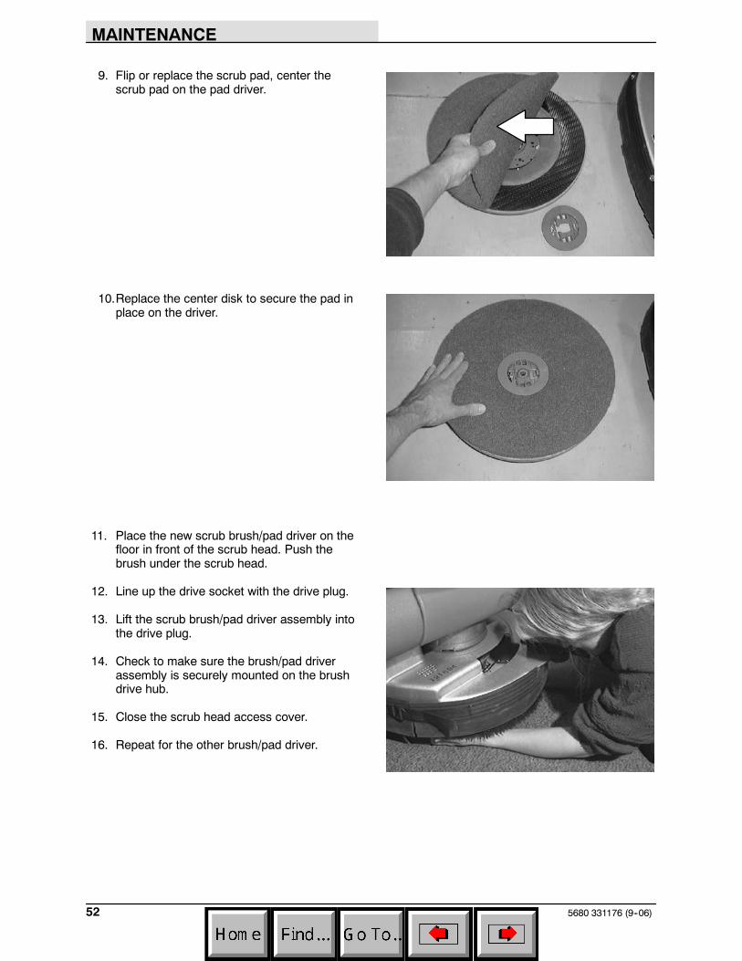
9. Flip or replace the scrub pad, center thescrub pad on the pad driver.
10.Replace the center disk to secure the pad inplace on the driver.
11. Place the new scrub brush/pad driver on thefloor in front of the scrub head. Push thebrush under the scrub head.
12. Line up the drive socket with the drive plug.
13. Lift the scrub brush/pad driver assembly intothe drive plug.
14. Check to make sure the brush/pad driverassembly is securely mounted on the brushdrive hub.
15. Close the scrub head access cover.
16. Repeat for the other brush/pad driver.
MAINTENANCE
535680 331176 (9--06)
CYLINDRICAL BRUSHES
Check the brush taper and rotate the brushesfrom front-to-rear every 50 hours of operation, formaximum brush life and best scrubbingperformance.
The cylinder brushes should be replaced if largeamounts of bristles are missing, or if theremaining bristles’ length is less than 10 mm(0.38 in).
NOTE: Be sure to replace brushes in sets.Otherwise one brush will be more aggressive thanthe other.
REPLACING THE CYLINDRICAL BRUSHES
1. Raise the scrub head.
2. Turn the machine power off and set theparking brake if your machine has thisoption.
FOR SAFETY: Before leaving orservicing machine, stop on levelsurface, and turn off machine.
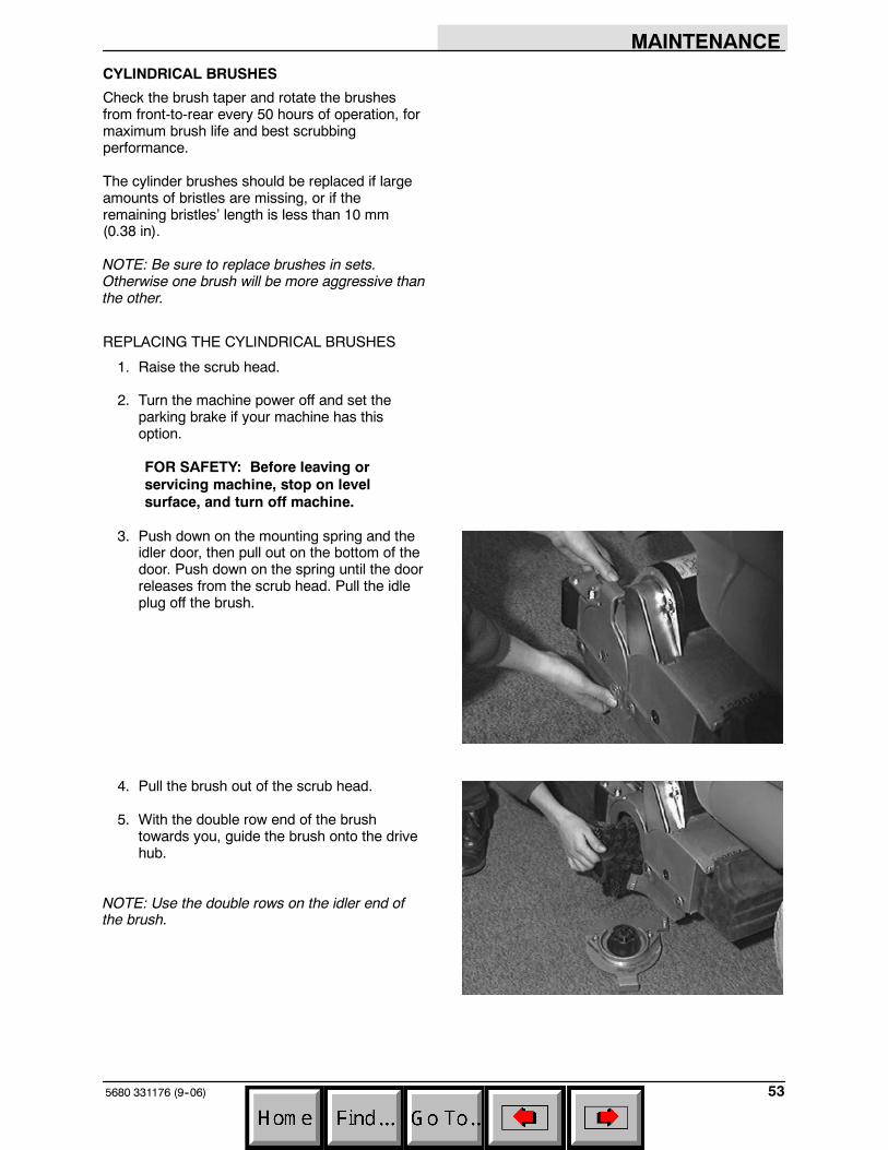
3. Push down on the mounting spring and theidler door, then pull out on the bottom of thedoor. Push down on the spring until the doorreleases from the scrub head. Pull the idleplug off the brush.
4. Pull the brush out of the scrub head.
5. With the double row end of the brushtowards you, guide the brush onto the drivehub.
NOTE: Use the double rows on the idler end ofthe brush.
MAINTENANCE
5680 331176 (9--06)54
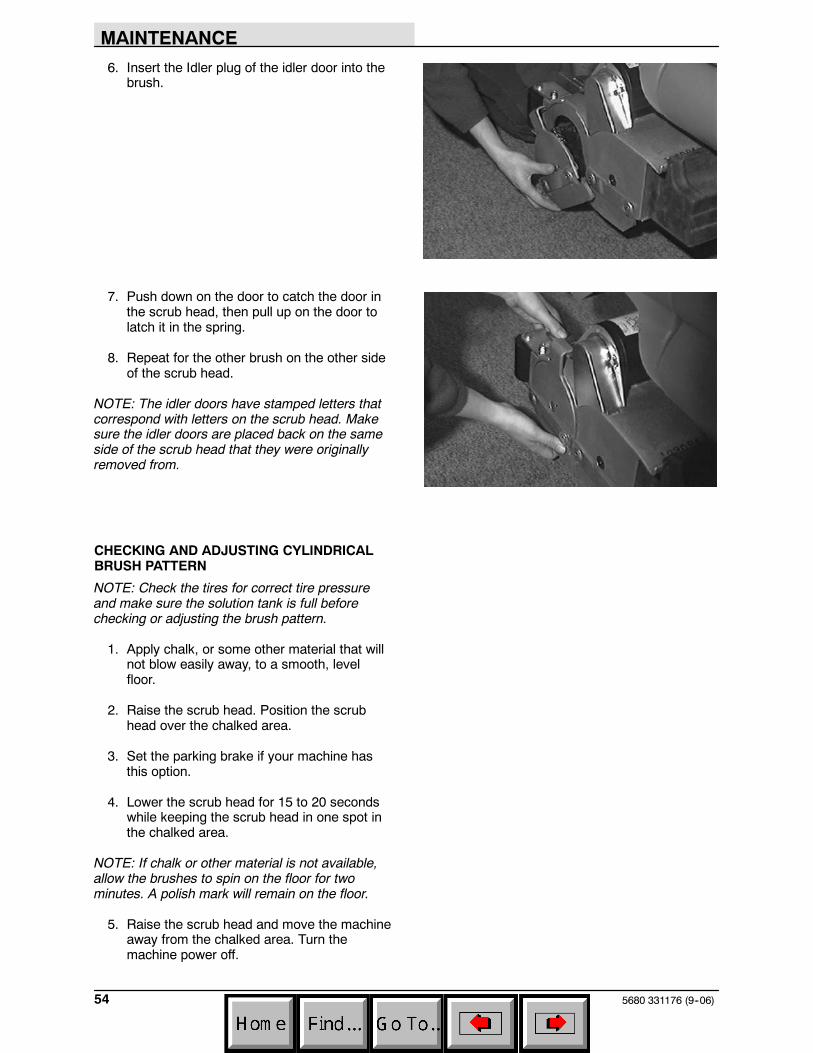
6. Insert the Idler plug of the idler door into thebrush.
7. Push down on the door to catch the door inthe scrub head, then pull up on the door tolatch it in the spring.
8. Repeat for the other brush on the other sideof the scrub head.
NOTE: The idler doors have stamped letters thatcorrespond with letters on the scrub head. Makesure the idler doors are placed back on the sameside of the scrub head that they were originallyremoved from.
CHECKING AND ADJUSTING CYLINDRICALBRUSH PATTERN
NOTE: Check the tires for correct tire pressureand make sure the solution tank is full beforechecking or adjusting the brush pattern.
1. Apply chalk, or some other material that willnot blow easily away, to a smooth, levelfloor.
2. Raise the scrub head. Position the scrubhead over the chalked area.
3. Set the parking brake if your machine hasthis option.
4. Lower the scrub head for 15 to 20 secondswhile keeping the scrub head in one spot inthe chalked area.
NOTE: If chalk or other material is not available,allow the brushes to spin on the floor for twominutes. A polish mark will remain on the floor.
5. Raise the scrub head and move the machineaway from the chalked area. Turn themachine power off.
MAINTENANCE
555680 331176 (9--06)
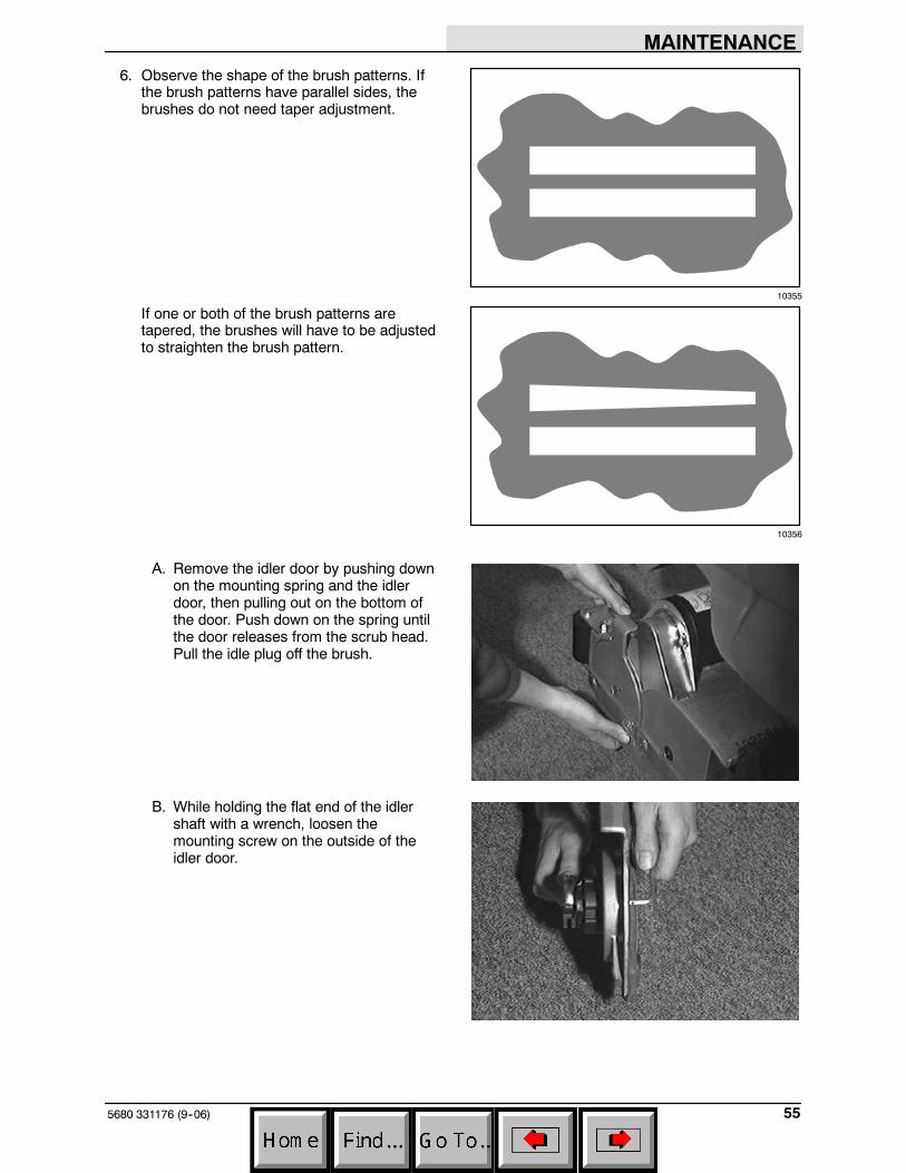
6. Observe the shape of the brush patterns. Ifthe brush patterns have parallel sides, thebrushes do not need taper adjustment.
If one or both of the brush patterns aretapered, the brushes will have to be adjustedto straighten the brush pattern.
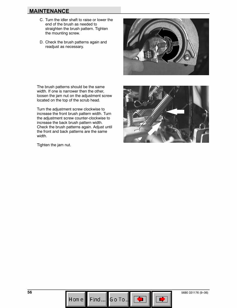
A. Remove the idler door by pushing downon the mounting spring and the idlerdoor, then pulling out on the bottom ofthe door. Push down on the spring untilthe door releases from the scrub head.Pull the idle plug off the brush.
B. While holding the flat end of the idlershaft with a wrench, loosen themounting screw on the outside of theidler door.
10355
10356
MAINTENANCE
5680 331176 (9--06)56
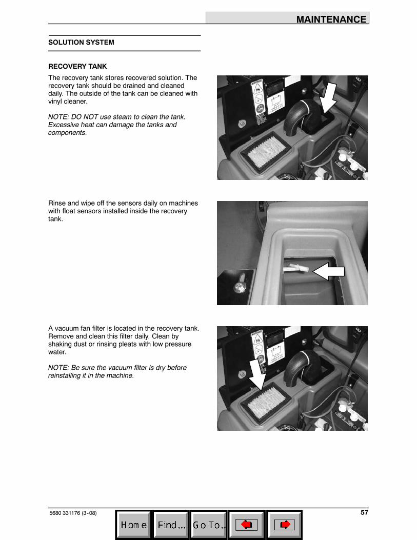
C. Turn the idler shaft to raise or lower theend of the brush as needed tostraighten the brush pattern. Tightenthe mounting screw.
D. Check the brush patterns again andreadjust as necessary.
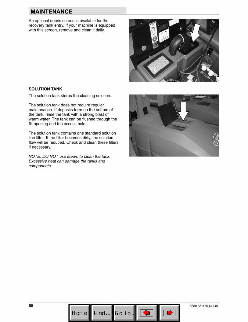
The brush patterns should be the samewidth. If one is narrower then the other,loosen the jam nut on the adjustment screwlocated on the top of the scrub head.
Turn the adjustment screw clockwise toincrease the front brush pattern width. Turnthe adjustment screw counter-clockwise toincrease the back brush pattern width.Check the brush patterns again. Adjust untilthe front and back patterns are the samewidth.
Tighten the jam nut.
MAINTENANCE
575680 331176 (3--08)
SOLUTION SYSTEM
RECOVERY TANK
The recovery tank stores recovered solution. Therecovery tank should be drained and cleaneddaily. The outside of the tank can be cleaned withvinyl cleaner.
NOTE: DO NOT use steam to clean the tank.Excessive heat can damage the tanks andcomponents.
Rinse and wipe off the sensors daily on machineswith float sensors installed inside the recoverytank.
A vacuum fan filter is located in the recovery tank.Remove and clean this filter daily. Clean byshaking dust or rinsing pleats with low pressurewater.
NOTE: Be sure the vacuum filter is dry beforereinstalling it in the machine.
MAINTENANCE
5680 331176 (3--08)58
An optional debris screen is available for therecovery tank entry. If your machine is equippedwith this screen, remove and clean it daily.
SOLUTION TANK
The solution tank stores the cleaning solution.
The solution tank does not require regularmaintenance. If deposits form on the bottom ofthe tank, rinse the tank with a strong blast ofwarm water. The tank can be flushed through thefill opening and top access hole.
The solution tank contains one standard solutionline filter. If the filter becomes dirty, the solutionflow will be reduced. Check and clean these filtersif necessary.
NOTE: DO NOT use steam to clean the tank.Excessive heat can damage the tanks andcomponents.
MAINTENANCE
595680 331176 (3--08)
FaST SYSTEM (OPTION)
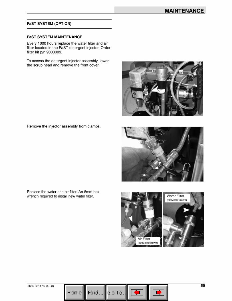
FaST SYSTEM MAINTENANCE
Every 1000 hours replace the water filter and airfilter located in the FaST detergent injector. Orderfilter kit p/n 9003009.
To access the detergent injector assembly, lowerthe scrub head and remove the front cover.
Remove the injector assembly from clamps.
Replace the water and air filter. An 8mm hexwrench required to install new water filter. Water Filter
(50 Mesh/Brown)
Air Filter(50 Mesh/Brown)
MAINTENANCE
5680 331176 (3--08)60
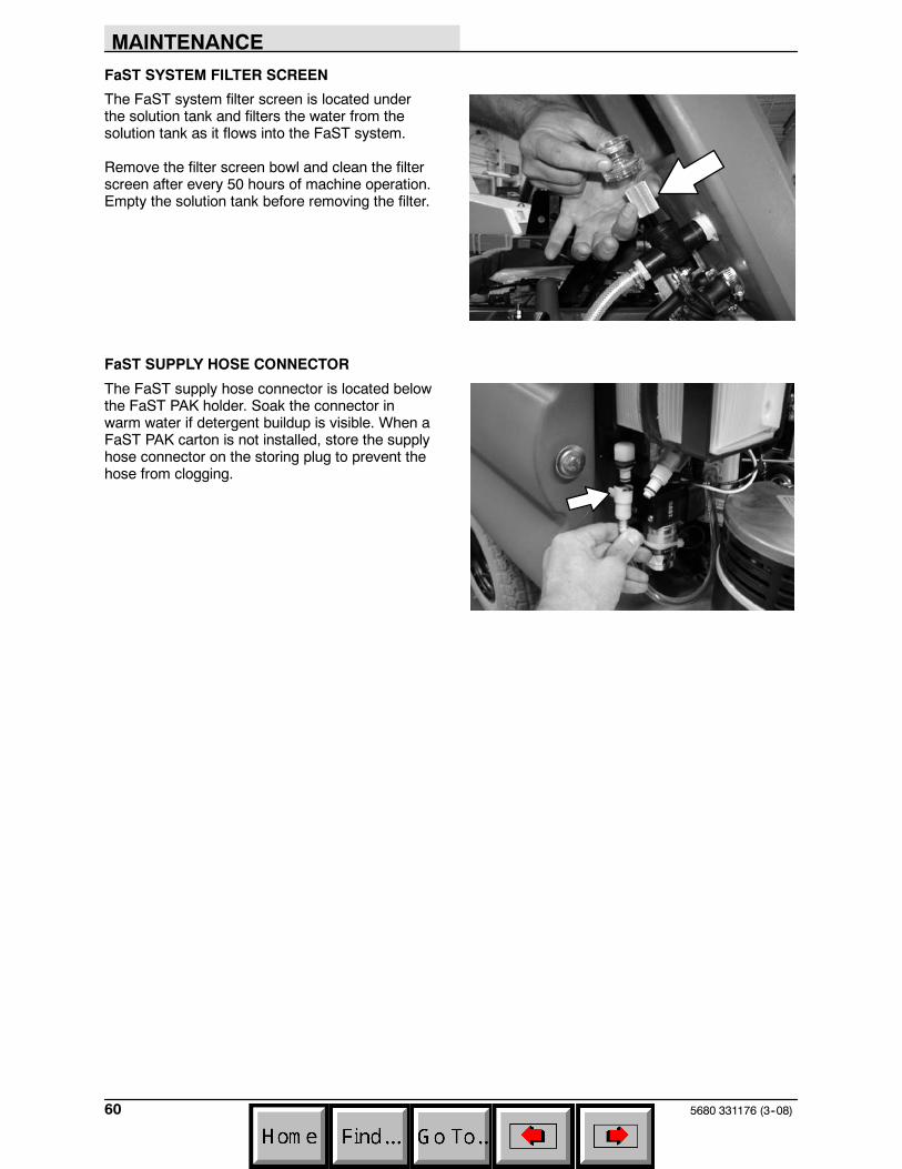
FaST SYSTEM FILTER SCREEN
The FaST system filter screen is located underthe solution tank and filters the water from thesolution tank as it flows into the FaST system.
Remove the filter screen bowl and clean the filterscreen after every 50 hours of machine operation.Empty the solution tank before removing the filter.
FaST SUPPLY HOSE CONNECTOR
The FaST supply hose connector is located belowthe FaST PAK holder. Soak the connector inwarm water if detergent buildup is visible. When aFaST PAK carton is not installed, store the supplyhose connector on the storing plug to prevent thehose from clogging.
MAINTENANCE
615680 331176 (09--08)
ec-H2O SYSTEM (OPTION)
ec-H2O MODULE FLUSH PROCEDURE
This procedure is only required when an alarmsounds and the ec--H2O system indicator lightbegins to blink red.
1. Drain the solution tank and recovery tank ofall water.
2. Pour 2 gallons (8 liters) of white or ricevinegar into the solution tank at full strength.Do not dilute.
NOTE: Use white or rice vinegar only. Theacidity level should be between 4--8%. Do not useother acids for this procedure.
FOR SAFETY: When servicing machine, wearprotective gloves and eye protection whenhandling vinegar.
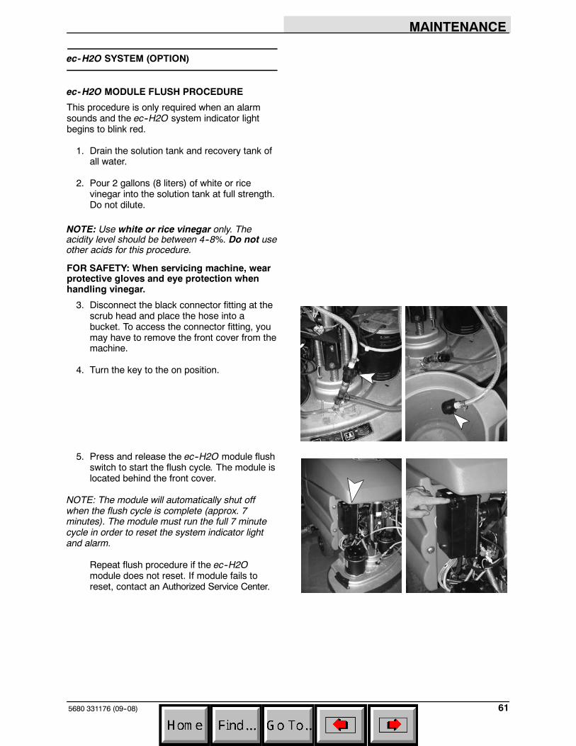
3. Disconnect the black connector fitting at thescrub head and place the hose into abucket. To access the connector fitting, youmay have to remove the front cover from themachine.
4. Turn the key to the on position.
5. Press and release the ec--H2O module flushswitch to start the flush cycle. The module islocated behind the front cover.
NOTE: The module will automatically shut offwhen the flush cycle is complete (approx. 7minutes). The module must run the full 7 minutecycle in order to reset the system indicator lightand alarm.
Repeat flush procedure if the ec--H2Omodule does not reset. If module fails toreset, contact an Authorized Service Center.
MAINTENANCE
5680 331176 (9--06)62
SQUEEGEE
The squeegee assembly channels water into thevacuum fan suction. The front blade channels thewater, and the rear blade wipes the floor.
Check the squeegee blades for damage and weardaily. Rotate or replace either of the squeegeeblades if the leading edge is torn or worn half-waythrough the thickness of the blade.
The squeegee can be adjusted for leveling anddeflection. The deflection and leveling of thesqueegee blades should be checked daily, orwhen scrubbing a different type of floor.
The squeegee assembly can be removed fromthe squeegee pivot to prevent damage duringtransport of the machine, or when changing to adifferent squeegee width. The squeegees areavailable in three widths to be used with the threedifferent model scrub heads; model 700 (700 mm(28 in)), model 800 (800 mm (32 in)), and model900 (900 mm (36 in)).
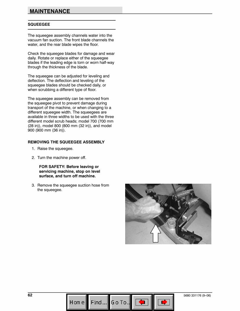
REMOVING THE SQUEEGEE ASSEMBLY
1. Raise the squeegee.
2. Turn the machine power off.
FOR SAFETY: Before leaving orservicing machine, stop on levelsurface, and turn off machine.
3. Remove the squeegee suction hose fromthe squeegee.
MAINTENANCE
635680 331176 (9--06)
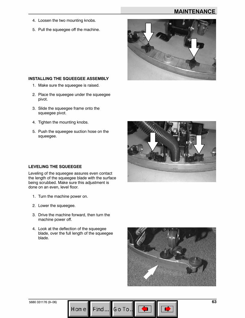
4. Loosen the two mounting knobs.
5. Pull the squeegee off the machine.
INSTALLING THE SQUEEGEE ASSEMBLY
1. Make sure the squeegee is raised.
2. Place the squeegee under the squeegeepivot.
3. Slide the squeegee frame onto thesqueegee pivot.
4. Tighten the mounting knobs.
5. Push the squeegee suction hose on thesqueegee.
LEVELING THE SQUEEGEE
Leveling of the squeegee assures even contactthe length of the squeegee blade with the surfacebeing scrubbed. Make sure this adjustment isdone on an even, level floor.
1. Turn the machine power on.
2. Lower the squeegee.
3. Drive the machine forward, then turn themachine power off.
4. Look at the deflection of the squeegeeblade, over the full length of the squeegeeblade.
MAINTENANCE
5680 331176 (9--06)64
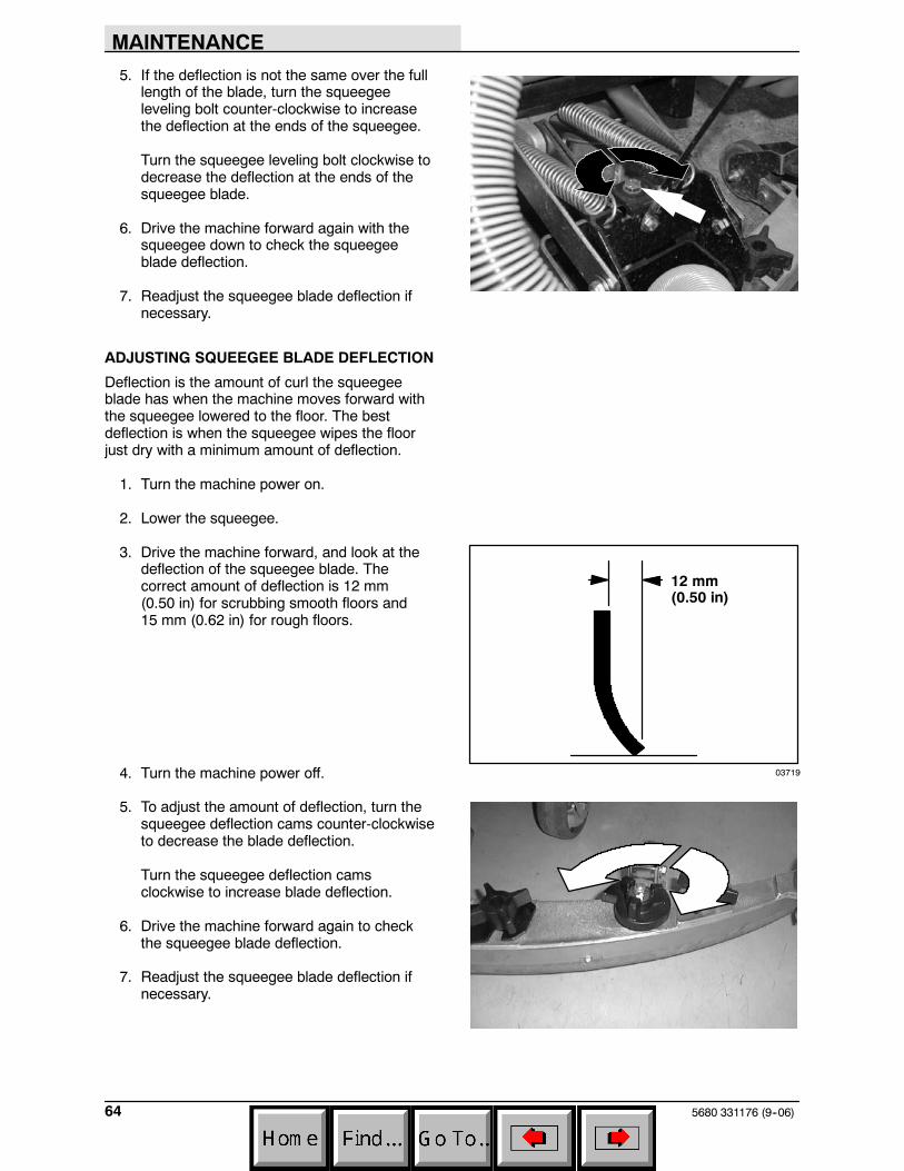
5. If the deflection is not the same over the fulllength of the blade, turn the squeegeeleveling bolt counter-clockwise to increasethe deflection at the ends of the squeegee.
Turn the squeegee leveling bolt clockwise todecrease the deflection at the ends of thesqueegee blade.
6. Drive the machine forward again with thesqueegee down to check the squeegeeblade deflection.
7. Readjust the squeegee blade deflection ifnecessary.
ADJUSTING SQUEEGEE BLADE DEFLECTION
Deflection is the amount of curl the squeegeeblade has when the machine moves forward withthe squeegee lowered to the floor. The bestdeflection is when the squeegee wipes the floorjust dry with a minimum amount of deflection.
1. Turn the machine power on.
2. Lower the squeegee.
3. Drive the machine forward, and look at thedeflection of the squeegee blade. Thecorrect amount of deflection is 12 mm(0.50 in) for scrubbing smooth floors and15 mm (0.62 in) for rough floors.
4. Turn the machine power off.
5. To adjust the amount of deflection, turn thesqueegee deflection cams counter-clockwiseto decrease the blade deflection.
Turn the squeegee deflection camsclockwise to increase blade deflection.
6. Drive the machine forward again to checkthe squeegee blade deflection.
7. Readjust the squeegee blade deflection ifnecessary.
03719
12 mm(0.50 in)
MAINTENANCE
655680 331176 (9--06)
SQUEEGEE BLADES
The squeegee has two squeegee blades, the frontand back. Each blade has four wiping edges. Touse them all, start with one wiping edge. To usethe next wiping edge, rotate the bladeend-for-end. To use the next wiping edge, rotatethe top edges down, bottom edges up. To use thelast edge, rotate the blade end-for-end.
Replace any worn or damaged squeegee blades.
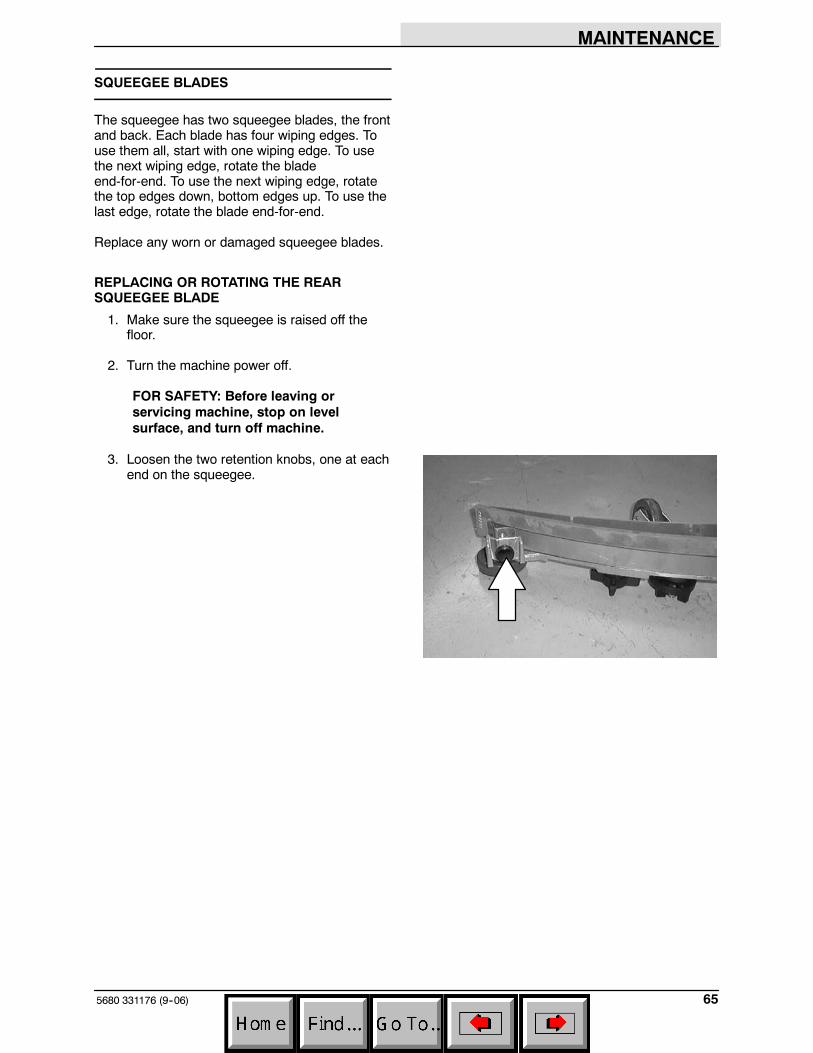
REPLACING OR ROTATING THE REARSQUEEGEE BLADE
1. Make sure the squeegee is raised off thefloor.
2. Turn the machine power off.
FOR SAFETY: Before leaving orservicing machine, stop on levelsurface, and turn off machine.
3. Loosen the two retention knobs, one at eachend on the squeegee.
MAINTENANCE
5680 331176 (9--06)66
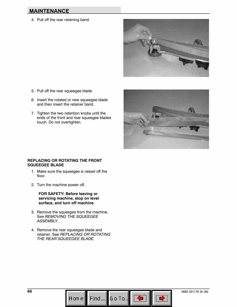
4. Pull off the rear retaining band.
5. Pull off the rear squeegee blade.
6. Insert the rotated or new squeegee bladeand then insert the retainer band.
7. Tighten the two retention knobs until theends of the front and rear squeegee bladestouch. Do not overtighten.
REPLACING OR ROTATING THE FRONTSQUEEGEE BLADE
1. Make sure the squeegee is raised off thefloor.
2. Turn the machine power off.
FOR SAFETY: Before leaving orservicing machine, stop on levelsurface, and turn off machine.
3. Remove the squeegee from the machine.See REMOVING THE SQUEEGEEASSEMBLY.
4. Remove the rear squeegee blade andretainer. See REPLACING OR ROTATINGTHE REAR SQUEEGEE BLADE.
MAINTENANCE
675680 331176 (9--06)
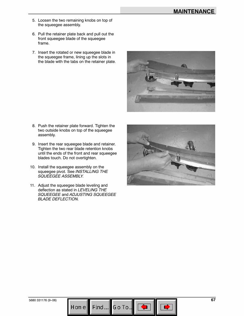
5. Loosen the two remaining knobs on top ofthe squeegee assembly.
6. Pull the retainer plate back and pull out thefront squeegee blade of the squeegeeframe.
7. Insert the rotated or new squeegee blade inthe squeegee frame, lining up the slots inthe blade with the tabs on the retainer plate.
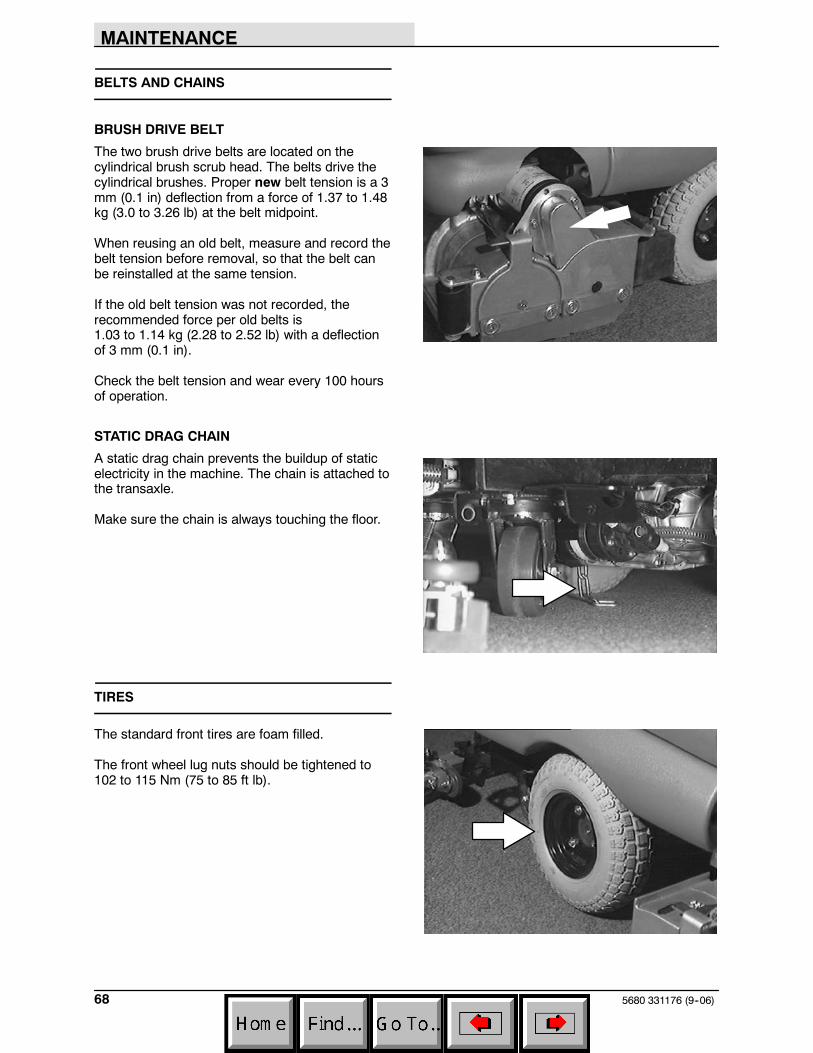
8. Push the retainer plate forward. Tighten thetwo outside knobs on top of the squeegeeassembly.
9. Insert the rear squeegee blade and retainer.Tighten the two rear blade retention knobsuntil the ends of the front and rear squeegeeblades touch. Do not overtighten.
10. Install the squeegee assembly on thesqueegee pivot. See INSTALLING THESQUEEGEE ASSEMBLY.
11. Adjust the squeegee blade leveling anddeflection as stated in LEVELING THESQUEEGEE and ADJUSTING SQUEEGEEBLADE DEFLECTION.
MAINTENANCE
5680 331176 (9--06)68
BELTS AND CHAINS
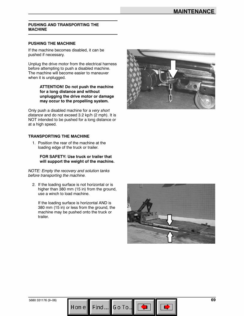
BRUSH DRIVE BELT
The two brush drive belts are located on thecylindrical brush scrub head. The belts drive thecylindrical brushes. Proper new belt tension is a 3mm (0.1 in) deflection from a force of 1.37 to 1.48kg (3.0 to 3.26 lb) at the belt midpoint.
When reusing an old belt, measure and record thebelt tension before removal, so that the belt canbe reinstalled at the same tension.
If the old belt tension was not recorded, therecommended force per old belts is1.03 to 1.14 kg (2.28 to 2.52 lb) with a deflectionof 3 mm (0.1 in).
Check the belt tension and wear every 100 hoursof operation.
STATIC DRAG CHAIN
A static drag chain prevents the buildup of staticelectricity in the machine. The chain is attached tothe transaxle.
Make sure the chain is always touching the floor.
TIRES
The standard front tires are foam filled.
The front wheel lug nuts should be tightened to102 to 115 Nm (75 to 85 ft lb).
MAINTENANCE
695680 331176 (9--06)
PUSHING AND TRANSPORTING THEMACHINE
PUSHING THE MACHINE
If the machine becomes disabled, it can bepushed if necessary.
Unplug the drive motor from the electrical harnessbefore attempting to push a disabled machine.The machine will become easier to maneuverwhen it is unplugged.
ATTENTION! Do not push the machinefor a long distance and withoutunplugging the drive motor or damagemay occur to the propelling system.
Only push a disabled machine for a very shortdistance and do not exceed 3.2 kp/h (2 mph). It isNOT intended to be pushed for a long distance orat a high speed.
TRANSPORTING THE MACHINE
1. Position the rear of the machine at theloading edge of the truck or trailer.
FOR SAFETY: Use truck or trailer thatwill support the weight of the machine.
NOTE: Empty the recovery and solution tanksbefore transporting the machine.
2. If the loading surface is not horizontal or ishigher than 380 mm (15 in) from the ground,use a winch to load machine.
If the loading surface is horizontal AND is380 mm (15 in) or less from the ground, themachine may be pushed onto the truck ortrailer.
MAINTENANCE
5680 331176 (9--06)70
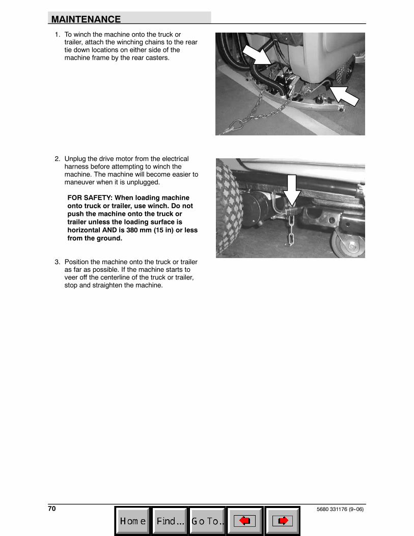
1. To winch the machine onto the truck ortrailer, attach the winching chains to the reartie down locations on either side of themachine frame by the rear casters.
2. Unplug the drive motor from the electricalharness before attempting to winch themachine. The machine will become easier tomaneuver when it is unplugged.
FOR SAFETY: When loading machineonto truck or trailer, use winch. Do notpush the machine onto the truck ortrailer unless the loading surface ishorizontal AND is 380 mm (15 in) or lessfrom the ground.
3. Position the machine onto the truck or traileras far as possible. If the machine starts toveer off the centerline of the truck or trailer,stop and straighten the machine.
MAINTENANCE
715680 331176 (9--06)
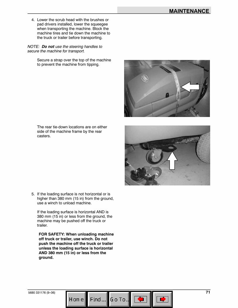
4. Lower the scrub head with the brushes orpad drivers installed, lower the squeegeewhen transporting the machine. Block themachine tires and tie down the machine tothe truck or trailer before transporting.
NOTE: Do not use the steering handles tosecure the machine for transport.
Secure a strap over the top of the machineto prevent the machine from tipping.
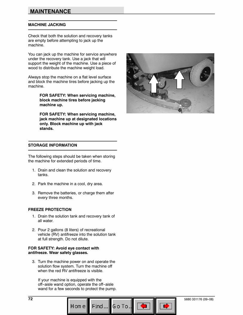
The rear tie-down locations are on eitherside of the machine frame by the rearcasters.
5. If the loading surface is not horizontal or ishigher than 380 mm (15 in) from the ground,use a winch to unload machine.
If the loading surface is horizontal AND is380 mm (15 in) or less from the ground, themachine may be pushed off the truck ortrailer.
FOR SAFETY: When unloading machineoff truck or trailer, use winch. Do notpush the machine off the truck or trailerunless the loading surface is horizontalAND 380 mm (15 in) or less from theground.
MAINTENANCE
5680 331176 (09--08)72
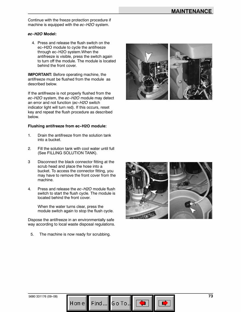
MACHINE JACKING
Check that both the solution and recovery tanksare empty before attempting to jack up themachine.
You can jack up the machine for service anywhereunder the recovery tank. Use a jack that willsupport the weight of the machine. Use a piece ofwood to distribute the machine weight load.
Always stop the machine on a flat level surfaceand block the machine tires before jacking up themachine.
FOR SAFETY: When servicing machine,block machine tires before jackingmachine up.
FOR SAFETY: When servicing machine,jack machine up at designated locationsonly. Block machine up with jackstands.
STORAGE INFORMATION
The following steps should be taken when storingthe machine for extended periods of time.
1. Drain and clean the solution and recoverytanks.
2. Park the machine in a cool, dry area.
3. Remove the batteries, or charge them afterevery three months.
FREEZE PROTECTION
1. Drain the solution tank and recovery tank ofall water.
2. Pour 2 gallons (8 liters) of recreationalvehicle (RV) antifreeze into the solution tankat full strength. Do not dilute.
FOR SAFETY: Avoid eye contact withantifreeze. Wear safety glasses.
3. Turn the machine power on and operate thesolution flow system. Turn the machine offwhen the red RV antifreeze is visible.
If your machine is equipped with theoff--aisle wand option, operate the off--aislewand for a few seconds to protect the pump.
MAINTENANCE
735680 331176 (09--08)
Continue with the freeze protection procedure ifmachine is equipped with the ec--H2O system.
ec-H2O Model:
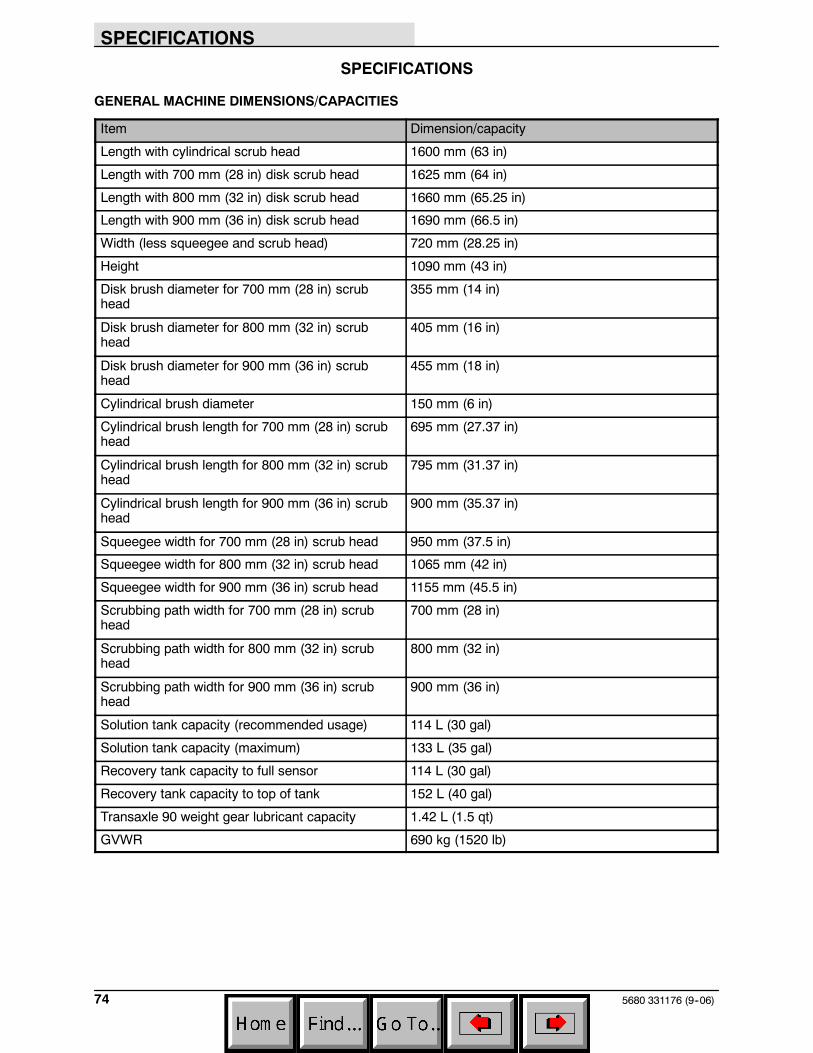
4. Press and release the flush switch on theec--H2O module to cycle the antifreezethrough ec--H2O system.When theantifreeze is visible, press the switch againto turn off the module. The module is locatedbehind the front cover.
IMPORTANT: Before operating machine, theantifreeze must be flushed from the module asdescribed below.
If the antifreeze is not properly flushed from theec--H2O system, the ec--H2O module may detectan error and not function (ec--H2O switchindicator light will turn red). If this occurs, resetkey and repeat the flush procedure as describedbelow.
Flushing antifreeze from ec--H2O module:
1. Drain the antifreeze from the solution tankinto a bucket.
2. Fill the solution tank with cool water until full(See FILLING SOLUTION TANK).
3 Disconnect the black connector fitting at thescrub head and place the hose into abucket. To access the connector fitting, youmay have to remove the front cover from themachine.
4. Press and release the ec--H2O module flushswitch to start the flush cycle. The module islocated behind the front cover.
When the water turns clear, press themodule switch again to stop the flush cycle.
Dispose the antifreeze in an environmentally safeway according to local waste disposal regulations.
5. The machine is now ready for scrubbing.
SPECIFICATIONS
5680 331176 (9--06)74
SPECIFICATIONS
GENERAL MACHINE DIMENSIONS/CAPACITIES
Item Dimension/capacity
Length with cylindrical scrub head 1600 mm (63 in)
Length with 700 mm (28 in) disk scrub head 1625 mm (64 in)
Length with 800 mm (32 in) disk scrub head 1660 mm (65.25 in)
Length with 900 mm (36 in) disk scrub head 1690 mm (66.5 in)
Width (less squeegee and scrub head) 720 mm (28.25 in)
Height 1090 mm (43 in)
Disk brush diameter for 700 mm (28 in) scrubhead
355 mm (14 in)
Disk brush diameter for 800 mm (32 in) scrubhead
405 mm (16 in)
Disk brush diameter for 900 mm (36 in) scrubhead
455 mm (18 in)
Cylindrical brush diameter 150 mm (6 in)
Cylindrical brush length for 700 mm (28 in) scrubhead
695 mm (27.37 in)
Cylindrical brush length for 800 mm (32 in) scrubhead
795 mm (31.37 in)
Cylindrical brush length for 900 mm (36 in) scrubhead
900 mm (35.37 in)
Squeegee width for 700 mm (28 in) scrub head 950 mm (37.5 in)
Squeegee width for 800 mm (32 in) scrub head 1065 mm (42 in)
Squeegee width for 900 mm (36 in) scrub head 1155 mm (45.5 in)
Scrubbing path width for 700 mm (28 in) scrubhead
700 mm (28 in)
Scrubbing path width for 800 mm (32 in) scrubhead
800 mm (32 in)
Scrubbing path width for 900 mm (36 in) scrubhead
900 mm (36 in)
Solution tank capacity (recommended usage) 114 L (30 gal)
Solution tank capacity (maximum) 133 L (35 gal)
Recovery tank capacity to full sensor 114 L (30 gal)
Recovery tank capacity to top of tank 152 L (40 gal)
Transaxle 90 weight gear lubricant capacity 1.42 L (1.5 qt)
GVWR 690 kg (1520 lb)
SPECIFICATIONS
755680 331176 (09--08)
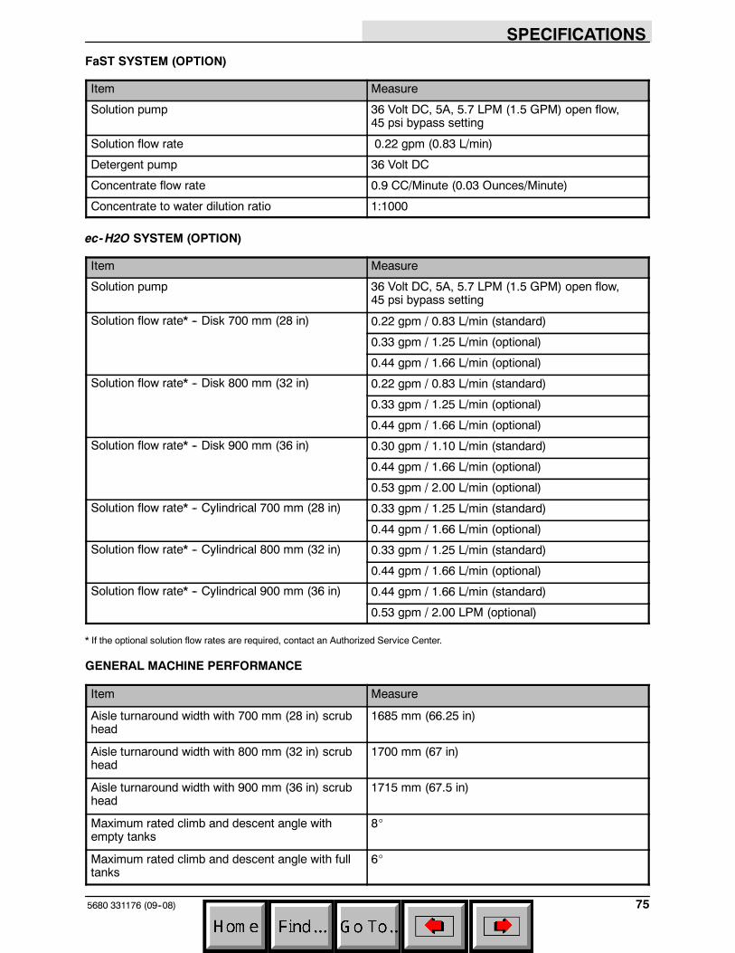
FaST SYSTEM (OPTION)
Item Measure
Solution pump 36 Volt DC, 5A, 5.7 LPM (1.5 GPM) open flow,45 psi bypass setting
Solution flow rate 0.22 gpm (0.83 L/min)
Detergent pump 36 Volt DC
Concentrate flow rate 0.9 CC/Minute (0.03 Ounces/Minute)
Concentrate to water dilution ratio 1:1000
ec-H2O SYSTEM (OPTION)
Item Measure
Solution pump 36 Volt DC, 5A, 5.7 LPM (1.5 GPM) open flow,45 psi bypass setting
Solution flow rate* -- Disk 700 mm (28 in) 0.22 gpm / 0.83 L/min (standard)
0.33 gpm / 1.25 L/min (optional)
0.44 gpm / 1.66 L/min (optional)
Solution flow rate* -- Disk 800 mm (32 in) 0.22 gpm / 0.83 L/min (standard)
0.33 gpm / 1.25 L/min (optional)
0.44 gpm / 1.66 L/min (optional)
Solution flow rate* -- Disk 900 mm (36 in) 0.30 gpm / 1.10 L/min (standard)
0.44 gpm / 1.66 L/min (optional)
0.53 gpm / 2.00 L/min (optional)
Solution flow rate* -- Cylindrical 700 mm (28 in) 0.33 gpm / 1.25 L/min (standard)
0.44 gpm / 1.66 L/min (optional)
Solution flow rate* -- Cylindrical 800 mm (32 in) 0.33 gpm / 1.25 L/min (standard)
0.44 gpm / 1.66 L/min (optional)
Solution flow rate* -- Cylindrical 900 mm (36 in) 0.44 gpm / 1.66 L/min (standard)
0.53 gpm / 2.00 LPM (optional)
* If the optional solution flow rates are required, contact an Authorized Service Center.
GENERAL MACHINE PERFORMANCE
Item Measure
Aisle turnaround width with 700 mm (28 in) scrubhead
1685 mm (66.25 in)
Aisle turnaround width with 800 mm (32 in) scrubhead
1700 mm (67 in)
Aisle turnaround width with 900 mm (36 in) scrubhead
1715 mm (67.5 in)
Maximum rated climb and descent angle withempty tanks
8_
Maximum rated climb and descent angle with fulltanks
6_
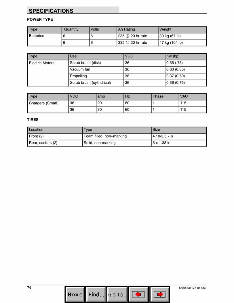
SPECIFICATIONS
5680 331176 (9--06)76
POWER TYPE
Type Quantity Volts Ah Rating Weight
Batteries 6 6 235 @ 20 hr rate 30 kg (67 lb)
6 6 335 @ 20 hr rate 47 kg (104 lb)
Type Use VDC Kw (hp)
Electric Motors Scrub brush (disk) 36 0.56 (.75)
Vacuum fan 36 0.63 (0.85)
Propelling 36 0.37 (0.50)
Scrub brush (cylindrical) 36 0.56 (0.75)
Type VDC amp Hz Phase VAC
Chargers (Smart) 36 20 60 1 115
36 30 60 1 115
TIRES
Location Type Size
Front (2) Foam filled, non--marking 4.10/3.5 -- 6
Rear, casters (2) Solid, non-marking 5 x 1.38 in
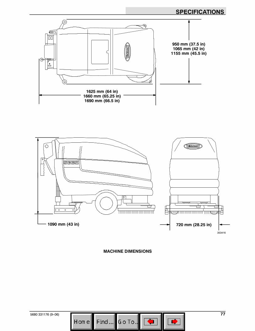
SPECIFICATIONS
775680 331176 (9--06)
1625 mm (64 in)1660 mm (65.25 in)1690 mm (66.5 in)
950 mm (37.5 in)1065 mm (42 in)1155 mm (45.5 in)
720 mm (28.25 in)1090 mm (43 in)
353416
MACHINE DIMENSIONS