Template for report - BIMMEPAUS · In-line centrifugal pumps. The pump families incorporate the...
23
BIM-MEP AUS SPECIFICATION Centrifugal pumps Issued By: BIM-MEP AUS 30 Cromwell Street, Burwood 3205 VIC Australia Revision: F Date September 2016
Transcript of Template for report - BIMMEPAUS · In-line centrifugal pumps. The pump families incorporate the...

BIM-MEPAUS SPECIFICATION
Centrifugal pumps
Issued By: BIM-MEPAUS
30 Cromwell Street, Burwood 3205 VIC Australia
Revision: F
Date September 2016

BIM-MEPAUS Specification
Centrifugal pumps
BIM-MEPAUS
September 2016
Acknowledgements BIM-MEPAUS acknowledges the contributions of the Pump Industry Australia Working Group and the following
organisations involved in the development of this document:
BKB Pumps
Grundfos Pumps
KSB Pumps
Tyco Pumps
Formatting conventions
The following table provides the text formats used in BIM-MEPAUS documentation and their application:
Text Type Example Indicates
Italicised text BIM Execution Plan The generic title for a type of document
Bold italicized text BIM-MEPAUS specification The name of a referenced document
Red bold text LOD First reference to a term or abbreviation that is
defined in the website glossary under Practices
Blue text www.bimmepaus.com.au Hyperlink / web link
Blue italicised text Explanatory notes Explanatory notes or reference information
Green bold text Future development Sections or documents that are still under
development by BIM-MEPAUS.
Keeping BIM-MEPAUS up-to-date
BIM-MEPAUS specifications, templates and content are updated to reflect changes in legislation, technology and
industry practice. Feedback and suggestions are welcome and can be made via the BIM-MEPAUS website. Updates
are managed and delivered through the BIM-MEPAUS website.
Liability Disclaimer
BIM-MEPAUS makes no warranty, expressed or implied, including but not limited to any implied warranties of
merchantability and fitness for a particular purpose, nor assumes any legal liability or responsibility for the accuracy,
completeness, or usefulness of the information in this document.
In no event shall BIM-MEPAUS or its agents be liable for damages or losses resulting from your use of, or reliance on
the information provided in this document.
COPYRIGHT © BIM-MEPAUS All rights reserved.

BIM-MEPAUS Specification
Centrifugal pumps
BIM-MEPAUS
September 2016
Table of Contents
1 INTRODUCTION .............................................................................................................. 1
1.1 Scope ........................................................................................................................................................ 1
1.2 References ................................................................................................................................................ 1
1.3 Objectives .................................................................................................................................................. 1
1.4 BIM-MEPAUS Schema ................................................................................................................................ 1
2 APPLICABLE STANDARDS ............................................................................................ 2
3 MODELS .......................................................................................................................... 3
3.1 Model workflow .......................................................................................................................................... 3
3.2 Generic design content .............................................................................................................................. 3
3.3 Manufacturer certified content ................................................................................................................... 4
4 SHARED PARAMETER SCHEDULING ........................................................................... 5
5 PUMP SPECIFICATION ................................................................................................... 7
5.1 Pump specification .................................................................................................................................... 7
5.2 Pump flanges ............................................................................................................................................ 7
5.3 Pump seals ................................................................................................................................................ 7
5.4 Net positive suction head .......................................................................................................................... 7
5.5 Pump motor selection ................................................................................................................................ 7
6 CLASSIFICATION AND FUNCTIONALITY ...................................................................... 8
6.1 Category .................................................................................................................................................... 8
6.2 Functional type and subtype ...................................................................................................................... 8
6.3 Family naming syntax ................................................................................................................................ 8
6.4 Family/type version control ........................................................................................................................ 9
6.5 Omniclass .................................................................................................................................................. 9
6.6 Connector settings ................................................................................................................................... 10
6.7 Family geometry ...................................................................................................................................... 10
7 PARAMETER SCHEDULES ...........................................................................................11
7.1 Identity Schedule ..................................................................................................................................... 11
7.2 BIM classification schedule ..................................................................................................................... 12
7.3 System analysis schedule ....................................................................................................................... 12
7.4 Green building properties schedule ......................................................................................................... 12
7.5 Performance/Quality schedule ................................................................................................................ 13
7.6 Manufacturer’s schedule ......................................................................................................................... 15
7.7 Commissioning schedule ......................................................................................................................... 16
7.8 Completion schedule ............................................................................................................................... 16
7.9 Generic design model schedule .............................................................................................................. 17
7.10 MCM schedule......................................................................................................................................... 19
BIM-MEPAUS Specification
Centrifugal pumps
BIM-MEPAUS Page 1 September 2016
1 INTRODUCTION
1.1 Scope
This document sets out the BIM-MEPAUS specification for the following families:
End suction centrifugal pumps - long coupled
End suction centrifugal pumps - short coupled
In-line centrifugal pumps.
The pump families incorporate the following pump assembly components:
Pump casing/impeller
Electric motor
Couplings, and
Base plate.
Pump inertia bases and mounts are provided under a separate equipment specification.
1.2 References
This specification should be read in conjunction with the following specifications and documents:
BIM-MEPAUS Piping systems, plant and equipment schedule – this Excel based schedule provides the
complete listing of piping systems, plant and equipment names as well as the system colour schema.
BIM-MEPAUS Master Shared Parameter Schedule – this document provides the reference source for all
shared parameter names used within BIM-MEPAUS Generic Design and manufacturer certified model
(MCM) content models together with the Revit MEP classification of each parameter and its associated
BIM-MEPAUS GUID.
BIM-MEPAUS Centrifugal Pump Product Templates – this Excel based schedule provides the complete
listing of the IFM and generic design family size catalogue together with product shared parameters and
product data templates.
BIM-MEPAUS Plant, equipment and fitting scheduling specification– this document details the
technical and workflow requirements in relation to shared parameter scheduling.
These documents can be accessed through the BIM-MEPAUS website.
1.3 Objectives
Benefits sought through the development and implementation of this BIM-MEPAUS specification include:
A structured approach to the specification and modelling of pumps;
Reliable and accurate Design to Commissioned As-built workflows; and
Industry standardization delivering improved supply chain efficiency and reduced project costs and risks
to the client and project team.
1.4 BIM-MEPAUS Schema
Within BIM-MEPAUS the plant, equipment and fitting schema is used to determine the component life cycle
scheduling and modelling requirements, pumps are classified as plant, sub-classification applied product.

BIM-MEPAUS Specification
Centrifugal pumps
BIM-MEPAUS Page 2 September 2016
2 APPLICABLE STANDARDS
There are a number of requirements in the National Construction Code as well as relevant Australian and
international standards that relate to pump design, efficiency and selection as well as test methods.
Codes and standards referenced in this specification include:
General Requirements
NCC/ BCA : National Construction Code / Building Code of Australia
Pumps
ISO 2858 : End-suction centrifugal pumps (rating 1600kPA or 16 bar) – Designation,
nominal duty point and dimensions;
DIN 24255 (EN 733) : End-suction centrifugal pumps with bearing bracket - Nominal duty point, main
dimensions and designation system (PN 10bar)
Guidelines referenced in this specification include:
AIRAH
Design Guide DA-01 : Design application manual for centrifugal pumps.

BIM-MEPAUS Specification
Centrifugal pumps
BIM-MEPAUS Page 3 September 2016
3 MODELS
3.1 Model workflow
One of the principle aims of BIM-MEPAUS is to enable efficient BIM workflows that see the design model
progressively refined through the design, virtual build and construction process to ultimately deliver a completed
Commissioned As-built Model.
A key step in this process is the change-out of the generic design components with manufacturer’s certified model
(MCM) components during the virtual build process. These MCMs are then able to be leveraged through
construction and commissioning workflows as well as ultimately life cycle asset and facility management systems.
The construction model generated through the virtual build is used to drive site layout, procurement and installation
scheduling activities as well as commissioning BIM to field processes.
Once the installation is completed and the systems commissioned, as-built data including any site changes and
commissioning data together is combined with the project completion data to finalise the Commissioned-As Built
Model for handover to the client.
3.2 Generic design content
BIM-MEPAUS generic design families provide a catalogue of sizes (types) that allow designers to spatially model to
LOD 300 as well as specify the pump’s performance and quality requirements.
The generic design model shared parameters have been developed through industry consultation and are
considered those necessary to schedule the quality and performance requirements for tendering and procurement
purposes.
Design firms with content libraries can pre-populate these pump design families with their specific quality
specifications in order to reduce repetitive data entry on each use in a project. This approach limits subsequent
scheduling to only those instance based performance parameters that are typically scheduled in specification
equipment schedules.
The generic design pump catalogue of sizes is selected to provide a representative range of typical selections
based on ISO 2858 Series pumps and Table E Flanges
BIM-MEPAUS uses the ISO pump designation system incorporating the following simplified syntax:
discharge size – impeller size
plus the electric motor designation
Motor kW / Poles.
A representative selection for a pump based on an ISO 150x125-315 with a 37.0kW / 4 Pole Motor would be:
125-315_EM37.0/4
The selected sizes for the IFMs are based on standard 4 pole 1450 rpm pumps
32-160_EM0.55/4
32-200_EM1.1/4
50-250_EM4.0/4
80-250_EM7.5/4
100-315_EM20.0/4
125-315_EM30.0/4
150-400_EM75.0/4

BIM-MEPAUS Specification
Centrifugal pumps
BIM-MEPAUS Page 4 September 2016
3.3 Manufacturer certified content
The virtual build develops the design model into the LOD 400 construction model and typically involves changing
out the design content with manufacturer certified content. Where the manufacturer’s model is BIM-MEPAUS
compliant this should be easily completed.
Manufacturer’s models are preferably generated from the BIM-MEPAUS industry foundation models (IFM) and are a
single type family that also provides the manufacturer specific instance based shared parameter data for the
component to be supplied to the project.
BIM-MEPAUS certified manufacturer models are fully interchangeable with the generic design models and provide:
Accurate geometry
Performance data
Full BIM-MEPAUS Revit operability.
Where the data is not able to be provided by the manufacturer in Revit content format - manufacturer’s shared
parameter data should be delivered in Excel format structured to allow the data to be imported by the specialist
trade installer into a scheduling database or virtual build model.
Microsoft Excel based product data templates are provided for this purpose on the BIM-MEPAUS website under
specification product templates.
As the MCM and supporting shared parameter schedule replaces the certified drawings and technical schedules
that have traditionally been provided by manufacturers, the model accuracy should be no more, or less than, that
provided by a manufacturer’s certified drawing.
Manufacturer’s data should provide a link to a web or pdf page providing installation guidelines and checklists for
modellers and shop drawers to facilitate the proper incorporation of the component into the model as well as the
pre-commissioning checks sheet for the commissioning team.
BIM-MEPAUS Specification
Centrifugal pumps
BIM-MEPAUS Page 5 September 2016
4 SHARED PARAMETER SCHEDULING
The shared parameter schema has been developed to effectively support data requirements for design,
procurement and commissioning as well as life cycle asset management.
All BIM-MEPAUS plant and equipment models have the same schedule structure shown below.
Identity
BIM Classification
System Analysis
Green Building Properties
Performance / Quality
Manufacturer
Commissioning
Completion
System Analysis, Green Building Properties and Commissioning schedules are only included where applicable and
have been adequately defined by a relevant standard.
The schedules are progressively completed as the MEP services model progresses through design and virtual
construction to a fully completed Commissioned As-built component within the final model.
Schedule Section Schedule Schedule completion by
Identity Generic design model Designer / Manufacturer / Installer
BIM Classification Generic design model Designer
System Analysis Generic design model Designer
Green Building Properties Generic design model / MCM model Designer / Installer / Manufacturer
Performance /Quality Generic design model / MCM model Designer / Installer
Manufacturer MCM model Manufacturer
Commissioning MCM model Installer
Completion Schedule MCM model Installer
The identity and completion schedules must be completed for all components and once the values are defined are
fixed for the life of the component.
It is expected that not all data will be carried in the Revit design or virtual construction model with non-core data
likely to be managed off model using scheduling databases and/or spreadsheets. This non-core data is commonly
required for the finalization of procurement, commissioning and facility management purposes.
Manufacturer BIM data must be supplied in a format that can be imported into a data management system and/or
Revit based Virtual Construction model with suitable formats including:
MCM model incorporating BIM-MEPAUS Product Data Template shared parameters
MCM geometry model with supporting BIM-MEPAUS Product Data Template Excel file.
To allow efficient and reliable data exchanges, it is critical that the BIM-MEPAUS shared parameter names and
respective GUIDs be used.
Parameters indicated in bold font are core Revit model data expected to reside in the model whilst those in italics
are non-core data and can be managed either in the model or off model in a scheduling database.

BIM-MEPAUS Specification
Centrifugal pumps
BIM-MEPAUS Page 6 September 2016
Parameters notated with the symbol have an industry defined set of allowable values or descriptors that are
listed in the master BIM-MEPAUS shared parameter schedule.
It is noted that BIM-MEPAUS compliant manufacturer’s certified models can be used for the basis of design where deemed appropriate by the designer and/or where specific manufacturer plant and equipment is to be nominated.
BIM-MEPAUS Specification
Centrifugal pumps
BIM-MEPAUS Page 7 September 2016
5 PUMP SPECIFICATION
AIRAH Design Guide DA-01 Design application manual for centrifugal pumps provides a comprehensive
guideline to the pump selection.
The following additional guidance has been identified through the industry consultation process as particular areas
requiring focus in the completion of the pump quality and performance schedules.
5.1 Pump specification
The majority of HVAC pumps for applications up to 1400kPa are specified to comply with ISO 2858.
With respect to inline pumps there are no similar guidelines covering the geometry of the pump.
5.2 Pump flanges
Australian pumps are typically scheduled with Table E Flange connections rated for 1400kPA. Pumps can also be
supplied as standard:
a) Pumps DN32-150 PN16 Flanges b) Pumps DN200 and above PN10 Flanges
For applications, outside these parameters the pump will need to be specifically ordered.
5.3 Pump seals
Pump seals are generally selected on the basis of inlet suction pressure with the following criteria typically used
a) Max suction pressures with standard mechanical seal is generally 700kPa b) Balanced mechanical seals for suction pressures > 700 kPa
Where higher reliability and service life are key considerations, cartridge seals may be appropriate.
It is noted that packed seals are no longer supplied for HVAC applications.
5.4 Net positive suction head
Net positive suction head needs to be carefully considered where the pump static head is low and flows are high.
Roof mounted condenser water pumps are particularly prone to net positive suction head problems and need to be
carefully selected.
5.5 Pump motor selection
Motor IP ratings: Typically IP55 is considered adequate for most applications – higher IP ratings may be warranted
for specialized applications.
Thermistor protection is normally provided for all motors 75kW and over as standard, however for motors under this
size thermistor protection must be specified if required to be fitted.
Motors are generally based on 400V 3 Phase 50Hz 4 pole motor selections due to their lower noise and vibration
levels with the following standard range of motors sizes available:
1.5 7.5 18.5 55
2.2 9.5 22 75
4.0 11 30 90
Motor speeds are determined by the number of poles as follows:
2 Pole = 48 rev/s
4 Pole = 24 rev/s
6 Pole = 16 rev/s
8 Pole = 12 rev/s

BIM-MEPAUS Specification
Centrifugal pumps
BIM-MEPAUS Page 8 September 2016
6 CLASSIFICATION AND FUNCTIONALITY
6.1 Category
All pump families are designated in Revit MEP as mechanical equipment.
6.2 Functional type and subtype
The design and manufacture models functional type and sub-type are:
Functional type: Pump
Subtype: EndSuctionLongCoupled ;
EndSuctionCloseCoupled;
In-LineCentrifugal.
6.3 Family naming syntax
The Pump family naming convention is as follows
Format:
Generic Design: <Functional Type>_< Functional Subtype >_<Generic >_<BMA>
MCM: <Functional Type>_< Functional Subtype >_<Manufacturer>_<Type Descriptor>
Example:
Generic Design Model
Pump_EndSuctionLongCoupled_Generic_BMA
Family type size catalogue includes
Manufacturer Certified Model
Pump_EndSuctionLongCoupled_Manufacturer Name_ISO2585FlangeE
Specific Type: 32-160_EM5.5/4
BIM-MEPAUS Specification
Centrifugal pumps
BIM-MEPAUS Page 9 September 2016
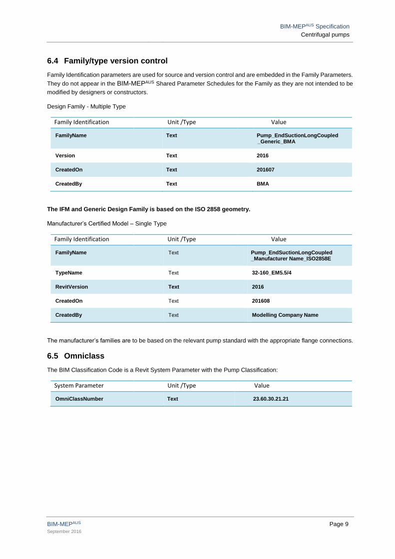
6.4 Family/type version control
Family Identification parameters are used for source and version control and are embedded in the Family Parameters.
They do not appear in the BIM-MEPAUS Shared Parameter Schedules for the Family as they are not intended to be
modified by designers or constructors.
Design Family - Multiple Type
Family Identification Unit /Type Value
FamilyName Text Pump_EndSuctionLongCoupled _Generic_BMA
Version Text 2016
CreatedOn Text 201607
CreatedBy Text BMA
The IFM and Generic Design Family is based on the ISO 2858 geometry.
Manufacturer’s Certified Model – Single Type
Family Identification Unit /Type Value
FamilyName Text Pump_EndSuctionLongCoupled _Manufacturer Name_ISO2858E
TypeName Text 32-160_EM5.5/4
RevitVersion Text 2016
CreatedOn Text 201608
CreatedBy Text Modelling Company Name
The manufacturer’s families are to be based on the relevant pump standard with the appropriate flange connections.
6.5 Omniclass
The BIM Classification Code is a Revit System Parameter with the Pump Classification:
System Parameter Unit /Type Value
OmniClassNumber Text 23.60.30.21.21

BIM-MEPAUS Specification
Centrifugal pumps
BIM-MEPAUS Page 10 September 2016
6.6 Connector settings
The following connectors are applied
ID Connector System Placement Shape/Type Calculation Method
1 Power - Balanced ELEC Face Power NA
2 Pipe - Suction GLOBAL Face Round Preset
3 Pipe - Discharge GLOBAL Face Round Calculated
6.7 Family geometry
Family Geometry is controlled by type based parameters with the intention that the modeller should not need to modify
the geometry of Generic Design Models or Manufacturer’s Certified Models.
It is noted that the Family Dimension Parameters are used to schedule those parameters that define the type (size or
capacity), with all detailed geometry dimensions listed separately under the Geometry Grouping.
Critical dimensions in relation to the model geometry are:
pipe flange connections
Inlet / outlet geometry
Inlet suction centre line to the bottom of the base plate.
Spring clearance – 0mm clearance indicates no springs fitted.
The IFM models are based on ISO 2858 pumps with Table E Flanges and 4 Pole 400/3/50 Electric Motors,
Manufacturer’s Certified Models will have correct geometry for alternative standards and flange arrangements.

BIM-MEPAUS Specification
Centrifugal pumps
BIM-MEPAUS Page 11 September 2016
7 PARAMETER SCHEDULES
The schedule structure and parameters were developed to meet the needs of the BIM-MEPAUS integrated project
delivery workflow as well as support asset life cycle requirements.
Refer to Section 4 - Shared Parameter Scheduling for a detailed overview of the intended use and application of the
schedules.
Parameter fields indicated in black bold text are provided with the generic design model.
7.1 Identity Schedule
Figure 7.1.1 Identity Schedule
Design Parameters Unit / Type Sample Value
ComponentName Text M _CHWP _32-2
SystemServed Text CHW
AreaServed Text High Rise
Location Text Level 32 Main AHU Plant room
PowerSource Text M_MSSB_32-1
EnergyMeterGrouping Text CHW Distribution
ComponentStatus Text CAB
MCM Parameters Unit /Type Sample Value
Manufacturer Text Manufacturer Name
Model Text LKGV ISO2585 Table E Flanges
ProductCode Text LKGV 125-315 /315 A2 – E-A-BGNZ
SerialNumber Text Serial Number
URL Text Hyperlink to product page
FM Parameters Unit /Type Sample Value
AssetIdentifier Text M _CHWP_32_2
Barcode Text Barcode Number
RFID Text RFID Tag Number
BIM-MEPAUS Specification
Centrifugal pumps
BIM-MEPAUS Page 12 September 2016
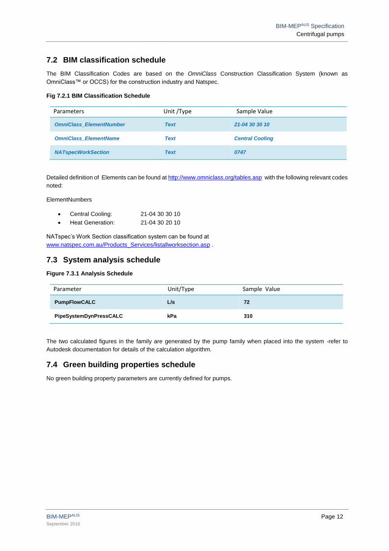
7.2 BIM classification schedule
The BIM Classification Codes are based on the OmniClass Construction Classification System (known as
OmniClass™ or OCCS) for the construction industry and Natspec.
Fig 7.2.1 BIM Classification Schedule
Parameters Unit /Type Sample Value
OmniClass_ElementNumber Text 21-04 30 30 10
OmniClass_ElementName Text Central Cooling
NATspecWorkSection Text 0747
Detailed definition of Elements can be found at http://www.omniclass.org/tables.asp with the following relevant codes
noted:
ElementNumbers
Central Cooling: 21-04 30 30 10
Heat Generation: 21-04 30 20 10
NATspec’s Work Section classification system can be found at
www.natspec.com.au/Products_Services/listallworksection.asp .
7.3 System analysis schedule
Figure 7.3.1 Analysis Schedule
Parameter Unit/Type Sample Value
PumpFlowCALC L/s 72
PipeSystemDynPressCALC kPa 310
The two calculated figures in the family are generated by the pump family when placed into the system -refer to
Autodesk documentation for details of the calculation algorithm.
7.4 Green building properties schedule
No green building property parameters are currently defined for pumps.

BIM-MEPAUS Specification
Centrifugal pumps
BIM-MEPAUS Page 13 September 2016
7.5 Performance/Quality schedule
The performance and quality schedule details the specified requirements for the pump – completion of the schedule
is generally considered equivalent to LOD 300.
The schedule brings together a number of typical specification section requirements including those related to pump
design and performance, mechanical-electrical system integration and vibration and noise isolation.
The Manufacturer’s certified model may overwrite some sections of the schedule replacing the design performance
requirements with manufacturer’s performance data.
Figure 7.5.1 Performance / Quality Schedule
Pump Details
Parameter Unit/Type Sample Value
PumpType Text Pump_EndSuctionLongCoupled
PumpStandard Text ISO 2858
PumpFlow L/s 72
PumpDynPress kPa 310
PumpDutyEfficiencyMin % 82
NPSHAvailable kPa 30
PumpSpeedMax RPM 2950
PumpSpeed RPM 1450
FluidType Text Water
DesignWorkingPress kPa 1200
FluidTempMax oC 90
FluidTempMin oC 5
PumpSealType Text Mechanical-Balanced
PumpWearRingMaterial Text Bronze
PumpCasingMaterial Text Cast Iron
ImpellerMaterial Text Bronze
ShaftMaterial Text Stainless 316
PipeConnectorType Text Table E Flange
Power Supply Details
Parameter Unit/Type Sample Value
SupplyVoltage V 400
SupplyPhase Ph 3
SupplyFrequency Hz 50
Starter_SpeedControlType Text VSD

BIM-MEPAUS Specification
Centrifugal pumps
BIM-MEPAUS Page 14 September 2016
Electric Motor Details
Parameter Unit/Type Sample Value
MotorSize kW 30
MotorPoles Integer 4
RLA Amps 40
FLA Amps 55
PowerFactorState Text Lagging
PowerFactor Number 0.8
MotorEfficiencyClass Text High Eff. AS/NZS 1359.5 -2004 B1
Motor_IP_Rating Number 55
MotorTropicProofing Yes/No No
MotorThermistorFitted Yes/No Yes
Mounting and Accessory Details
Parameter Unit/Type Sample Value
PumpDripTrayFitted Yes/No Yes
Basis of Design Details
Parameter Unit/Type Sample Value
BasisOfDesign Text Manufacturer Name / Model

BIM-MEPAUS Specification
Centrifugal pumps
BIM-MEPAUS Page 15 September 2016
7.6 Manufacturer’s schedule
Manufacturer’s schedules are completed by suppliers to confirm the detailed performance, quality and configuration
selections.
Figure 7.6.1 Manufacturer’s schedule
Pump Details
Parameter Unit/Type Sample Value
PumpSuctionDiameter mm 150
PumpDischargeDiameter mm 125
PumpImpellerSizeMax mm 342
PumpImpellerSizeMin mm 274
PumpImpellerSizeFitted mm 336
PumpImpellerSpeed RPM 1450
PumpDischargeVel m/s 5.95
PumpAbsorbedPower kW 31
PumpDutyEfficiency % 83.5
NCC_Section_J_Compliance Yes/No Yes
NPSHRequired kPa 24
Electric Motor Details
Parameter Unit/Type Sample Value
MotorManufacturer Text Manufacturer Name
MotorWindingInsulation Text F
MotorFrame Text D132
Assembly Details
Parameter Unit/Type Sample Value
TotalMass Kg 105
DimensionalTolerance mm 5
PreCommissionITP URL URL to Manufacturer’s ITP

BIM-MEPAUS Specification
Centrifugal pumps
BIM-MEPAUS Page 16 September 2016
7.7 Commissioning schedule
Commissioning schedules are based on NEBB and relevant Australian Standards and completed by the installer’s
commissioning team.
Figure 7.7.1 Commissioning Schedule
Parameter Unit/Type Sample Value
PumpSpeedActual RPM 1480
MotorAbsorbedPowerActual kW 31.7
MotorVoltageActual V 408
MotorAmpsActual Amps 52
OverloadSettingActual Amps 67
FuseRating Amps 0
DischargePressShutOffActual kPa 630
SuctionPressShutOffActual kPa 200
TotalPressShutOffActual kPa 430
DischargePressActual kPa 100
SuctionPressActual kPa 460
PumpDynPressActual kPa 360
PumpFlowActual L/s 73.5
CommissioningDate Text 2014-02-28
CommissioningTechnician Text Commissioning Technician’s Name
7.8 Completion schedule
The completion schedule provides key asset and facility maintenance data and is common for the BIM-MEPAUS plant
and equipment families:
Figure 7.8.1 – Completion Schedule
Parameter Unit/Type Sample Value
Designer Text Designer Name
Installer Text Installer Name
Client Text Client Name
InstallationDate Text 2013-09-31
MaintenanceType Text Schedule Preventive
OperationMaintenanceManual URL URL to O&M Manual
WarrantyDurationMonths Integer 12
ExpectedServiceLifeYears Integer 20

BIM-MEPAUS Specification
Centrifugal pumps
BIM-MEPAUS Page 17 September 2016
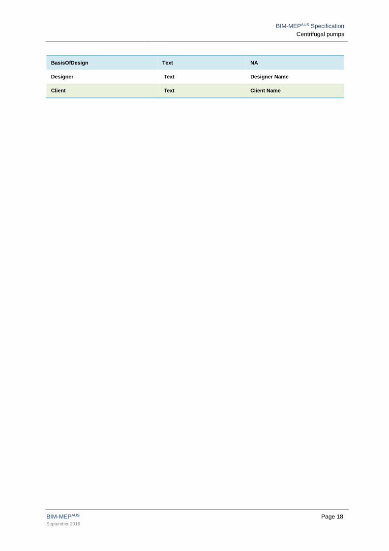
7.9 Generic design model schedule
The following schedule defines the Generic Design shared parameter schedule and default values for the generic
design model data schedule. The schedule is intended to be completed by the Designer to the extent required but as
a minimum would include the component name and power source.
Parameter Unit / Type Default Value
ComponentName Text Component Name
SystemServed Text System Name
AreaServed Text Area Name
Location Text Location Name
PowerSource Text Switchboard Name
EnergyMeterGrouping Text Meter Group Name
ComponentStatus Text DD
PumpType Text Pump_EndSuctionLongCoupled
PumpStandard Text ISO 2858
PumpFlow L/s 0
PumpDynPress kPa 0
PumpDutyEfficiencyMin % 0
NPSHAvailable kPa 0
PumpSpeed RPM 0
DesignWorkingPress kPa 0
PumpSealType Text Mechanical-Balanced
PipeConnectorType Text Table E Flange
SupplyVoltage V 400
SupplyPhase Ph 3
SupplyFrequency Hz 50
Starter_SpeedControlType Text VSD
MotorSize kW 0
RLA Amps 0
MotorEfficiencyClass Text High Eff. AS/NZS 1359.5 -2004 B1
Motor_IP_Rating Number 55
MotorTropicProofing Yes/No No
MotorThermistorFitted Yes/No No
PumpDripTrayFitted Yes/No No
BIM-MEPAUS Specification
Centrifugal pumps
BIM-MEPAUS Page 18 September 2016
BasisOfDesign Text NA
Designer Text Designer Name
Client Text Client Name

BIM-MEPAUS Specification
Centrifugal pumps
BIM-MEPAUS Page 19 September 2016
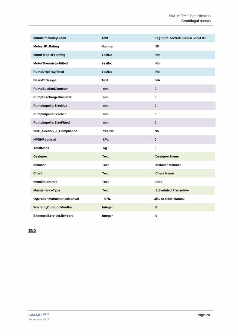
7.10 MCM schedule
The following schedule defines the IFM shared parameter schedule and default values that form the basis of the
manufacturers model data schedule for the Revit Manufacturer’s Certified Model and Commissioned As Built Model.
Parameter Unit/Type Default Value
ComponentName Text Component Name
SystemServed Text System Name
AreaServed Text Area Name
Location Text Location Name
PowerSource Text Switchboard Name
EnergyMeterGrouping Text Meter Group Name
ComponentStatus Text DD
Manufacturer Text Manufacturer Name
Model Text Model Name
ProductCode Text Product Code
SerialNumber Text Serial Number
URL Text URL
PumpType Text Pump_EndSuctionLongCoupled
PumpStandard Text ISO 2858
PumpFlow L/s 0
PumpDynPress kPa 0
PumpDutyEfficiencyMin % 0
NPSHAvailable kPa 0
PumpSpeed RPM 0
DesignWorkingPress kPa 0
PumpSealType Text Mechanical-Balanced
PipeConnectorType Text Table E Flange
SupplyVoltage V 400
SupplyPhase Ph 3
SupplyFrequency Hz 50
Starter_SpeedControlType Text VSD
MotorSize kW 0
RLA Amps 0
BIM-MEPAUS Specification
Centrifugal pumps
BIM-MEPAUS Page 20 September 2016
MotorEfficiencyClass Text High Eff. AS/NZS 1359.5 -2004 B1
Motor_IP_Rating Number 55
MotorTropicProofing Yes/No No
MotorThermistorFitted Yes/No No
PumpDripTrayFitted Yes/No No
BasisOfDesign Text NA
PumpSuctionDiameter mm 0
PumpDischargeDiameter mm 0
PumpImpellerSizeMax mm 0
PumpImpellerSizeMin mm 0
PumpImpellerSizeFitted mm 0
NCC_Section_J_Compliance Yes/No No
NPSHRequired kPa 0
TotalMass Kg 0
Designer Text Designer Name
Installer Text Installer Member
Client Text Client Name
InstallationDate Text Date
MaintenanceType Text Scheduled Preventive
OperationMaintenanceManual URL URL to O&M Manual
WarrantyDurationMonths Integer 0
ExpectedServiceLifeYears Integer 0
END