
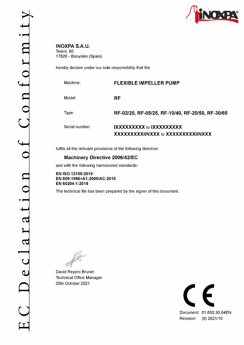
FLEXIBLE IMPELLER PUMP - INOXPA
28
INSTALLATION, SERVICE AND MAINTENANCE INSTRUCTIONS FLEXIBLE IMPELLER PUMP RF Original Instructions 01.650.30.02EN (B) 2021/10 01.650.32.0001
Transcript of FLEXIBLE IMPELLER PUMP - INOXPA
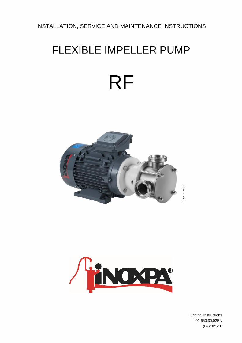
INSTALLATION, SERVICE AND MAINTENANCE INSTRUCTIONS
FLEXIBLE IMPELLER PUMP
RF
Original Instructions
01.650.30.02EN
(B) 2021/10
01
.65
0.3
2.0
00
1

4 INOXPA S.A.U. · 01.650.30.02EN · (B) 2021/10
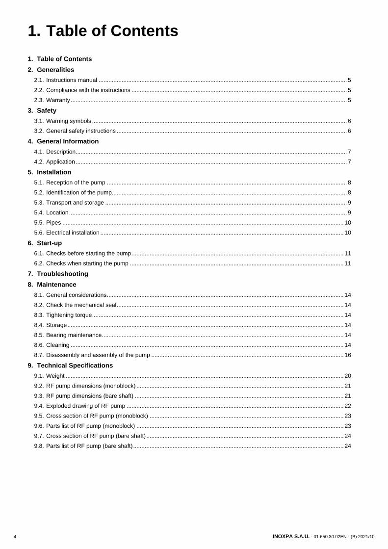
1. Table of Contents
1. Table of Contents
2. Generalities
2.1. Instructions manual ....................................................................................................................................................... 5
2.2. Compliance with the instructions ................................................................................................................................... 5
2.3. Warranty ........................................................................................................................................................................ 5
3. Safety
3.1. Warning symbols ........................................................................................................................................................... 6
3.2. General safety instructions ............................................................................................................................................ 6
4. General Information
4.1. Description ..................................................................................................................................................................... 7
4.2. Application ..................................................................................................................................................................... 7
5. Installation
5.1. Reception of the pump .................................................................................................................................................. 8
5.2. Identification of the pump............................................................................................................................................... 8
5.3. Transport and storage ................................................................................................................................................... 9
5.4. Location ......................................................................................................................................................................... 9
5.5. Pipes ........................................................................................................................................................................... 10
5.6. Electrical installation .................................................................................................................................................... 10
6. Start-up
6.1. Checks before starting the pump ................................................................................................................................. 11
6.2. Checks when starting the pump .................................................................................................................................. 11
7. Troubleshooting
8. Maintenance
8.1. General considerations ................................................................................................................................................ 14
8.2. Check the mechanical seal .......................................................................................................................................... 14
8.3. Tightening torque ......................................................................................................................................................... 14
8.4. Storage ........................................................................................................................................................................ 14
8.5. Bearing maintenance ................................................................................................................................................... 14
8.6. Cleaning ...................................................................................................................................................................... 14
8.7. Disassembly and assembly of the pump ..................................................................................................................... 16
9. Technical Specifications
9.1. Weight ......................................................................................................................................................................... 20
9.2. RF pump dimensions (monoblock) .............................................................................................................................. 21
9.3. RF pump dimensions (bare shaft) ............................................................................................................................... 21
9.4. Exploded drawing of RF pump .................................................................................................................................... 22
9.5. Cross section of RF pump (monoblock) ...................................................................................................................... 23
9.6. Parts list of RF pump (monoblock) .............................................................................................................................. 23
9.7. Cross section of RF pump (bare shaft) ........................................................................................................................ 24
9.8. Parts list of RF pump (bare shaft) ................................................................................................................................ 24
Generalities
INOXPA S.A.U. · 01.650.30.02EN · (B) 2021/10 5
2. Generalities
2.1. INSTRUCTIONS MANUAL
This manual contains information regarding the reception, installation, operation, assembly, disassembly and maintenance of the RF pumps.
Carefully read the instruction before starting the pump, familiarize yourself with the installation, operation and correct use of the pump and strictly follow the instructions. These instructions should be kept in a safe location near the installation area.
The information published in the instruction manual is based on updated data.
INOXPA reserves the right to modify this instruction manual without prior notice.
2.2. COMPLIANCE WITH THE INSTRUCTIONS
Not following the instructions may impose a risk for the operators, the environment and the machine, and may result in the loss of the right to claim damages.
This non-compliance may result in the following risks:
• failure of important machine/plant functions,
• failure of specific maintenance and repair procedures,
• possible electrical, mechanical and chemical hazards,
• risk to the environment due to the type of substances released.
2.3. WARRANTY
Any warranty will be void immediately and lawfully and, additionally, INOXPA will be compensated for any civil liability claims submitted by third parties, in the following cases:
• the service and maintenance work has not been carried out in accordance with the service instructions, the repairs have not been carried out by our personnel or have been carried out without our written authorisation,
• modifications have been carried out on our material or equipment without written authorisation,
• the parts or lubricants used are not original INOXPA parts and products,
• the material or equipment has been improperly used, has been used negligently, or has not been used according to the instructions and their intended,
• the pump parts are damaged because they have been subjected to high pressure due to not having used a safety valve.
The General Conditions of Delivery already in your possession are also applicable.
The machine may not undergo any modification without prior approval from the manufacturer.
For your safety, only use original spare parts and accessories.
The usage of other parts will relieve the manufacturer of any liability.
Changing the service conditions can only be carried out with prior written authorization from INOXPA.
Please do not hesitate to contact us in case of doubts or if further explanations are required regarding specific data (adjustments, assembly, disassembly, etc.).
Safety
6 INOXPA S.A.U. · 01.650.30.02EN · (B) 2021/10
3. Safety
3.1. WARNING SYMBOLS
Safety hazard for people in general and/or for equipment
Electric hazard
Important instruction for the protection of the equipment and its functions
3.2. GENERAL SAFETY INSTRUCTIONS
Read the instruction manual carefully before installing and starting the pump. Contact INOXPA in case of doubt.
3.2.1. During the installation
The 9. Technical Specifications of chapter 9 should always be observed.
Never start the pump before connecting it to the lines.
Do not operate the pump if the pump cover is not fitted.
Check for proper specifications of the motors, especially its working conditions create an explosions hazard.
During the installations, all the electric work should be carried out by authorized personnel.
3.2.2. During operation
The Technical Specifications of chapter 9 should always be observed. Under no circumstances can the specified limit values be exceeded.
NEVER touch the pump or the pipework during operation if the pump is being used for transferring hot liquids or during cleaning.
The pump contains moving parts. Never place your fingers inside the pump during operation.
NEVER operate with the suction and discharge valves closed.
NEVER spray water directly on the electrical motor. The standard motor protection is IP55: protection against dust and water spray.
3.2.3. During maintenance
The Technical Specifications of chapter 9 shall always be observed.
NEVER disassemble the pump until the pipes have been emptied. Remember that liquid will remain inside the pump’s pump casing (if does not have a purge). Bear in mind that the pumped liquid may be hazardous or extremely hot. Consult the regulations in effect in each country for these cases.
Do not leave loose parts on the floor.
ALWAYS disconnect the electrical power to the pumps before carrying out any maintenance.
Remove the fuses and disconnect the cable from the motor’s terminals.
All electrical work must be carried out by authorized personnel.
ATTENTION
General Information
INOXPA S.A.U. · 01.650.30.02EN · (B) 2021/10 7
4. General Information
4.1. DESCRIPTION
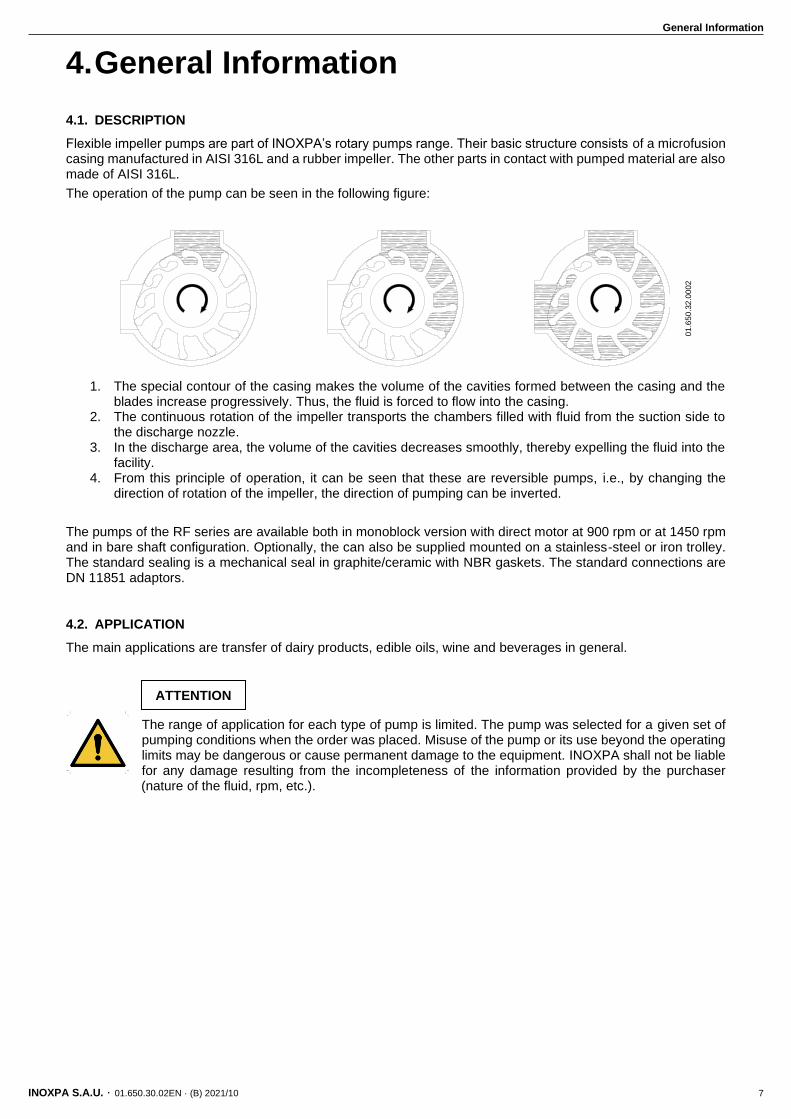
Flexible impeller pumps are part of INOXPA’s rotary pumps range. Their basic structure consists of a microfusion casing manufactured in AISI 316L and a rubber impeller. The other parts in contact with pumped material are also made of AISI 316L.
The operation of the pump can be seen in the following figure:
1. The special contour of the casing makes the volume of the cavities formed between the casing and the blades increase progressively. Thus, the fluid is forced to flow into the casing.
2. The continuous rotation of the impeller transports the chambers filled with fluid from the suction side to the discharge nozzle.
3. In the discharge area, the volume of the cavities decreases smoothly, thereby expelling the fluid into the facility.
4. From this principle of operation, it can be seen that these are reversible pumps, i.e., by changing the direction of rotation of the impeller, the direction of pumping can be inverted.
The pumps of the RF series are available both in monoblock version with direct motor at 900 rpm or at 1450 rpm and in bare shaft configuration. Optionally, the can also be supplied mounted on a stainless-steel or iron trolley. The standard sealing is a mechanical seal in graphite/ceramic with NBR gaskets. The standard connections are DN 11851 adaptors.
4.2. APPLICATION
The main applications are transfer of dairy products, edible oils, wine and beverages in general.
The range of application for each type of pump is limited. The pump was selected for a given set of pumping conditions when the order was placed. Misuse of the pump or its use beyond the operating limits may be dangerous or cause permanent damage to the equipment. INOXPA shall not be liable for any damage resulting from the incompleteness of the information provided by the purchaser (nature of the fluid, rpm, etc.).
ATTENTION 0
1.6
50
.32
.00
02
Installation
8 INOXPA S.A.U. · 01.650.30.02EN · (B) 2021/10
5. Installation
5.1. RECEPTION OF THE PUMP
INOXPA cannot be held responsible for the damage sustained by the equipment during transport or unpacking. Please visually check that the packaging is not damaged.
The pump package includes the following documents:
• shipping documents,
• installation, service and maintenance instructions manual,
• instructions and service manual of the motor1.
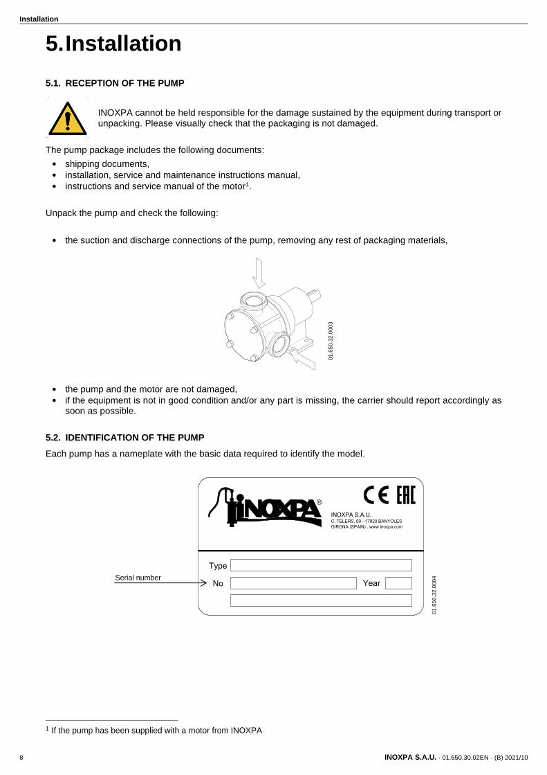
Unpack the pump and check the following:
• the suction and discharge connections of the pump, removing any rest of packaging materials,
• the pump and the motor are not damaged,
• if the equipment is not in good condition and/or any part is missing, the carrier should report accordingly as soon as possible.
5.2. IDENTIFICATION OF THE PUMP
Each pump has a nameplate with the basic data required to identify the model.
1 If the pump has been supplied with a motor from INOXPA
Serial number
01
.65
0.3
2.0
00
3
01
.65
0.3
2.0
00
4
Installation
INOXPA S.A.U. · 01.650.30.02EN · (B) 2021/10 9
5.3. TRANSPORT AND STORAGE
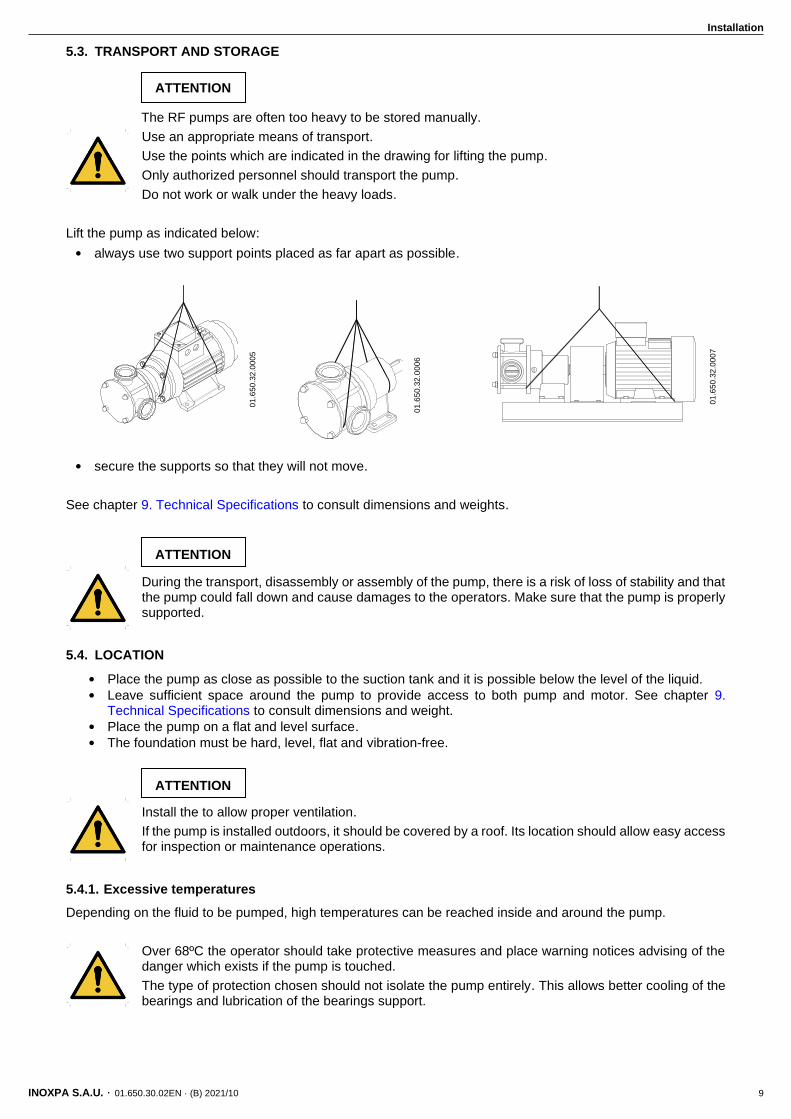
The RF pumps are often too heavy to be stored manually.
Use an appropriate means of transport.
Use the points which are indicated in the drawing for lifting the pump.
Only authorized personnel should transport the pump.
Do not work or walk under the heavy loads.
Lift the pump as indicated below:
• always use two support points placed as far apart as possible.
• secure the supports so that they will not move.
See chapter 9. Technical Specifications to consult dimensions and weights.
During the transport, disassembly or assembly of the pump, there is a risk of loss of stability and that the pump could fall down and cause damages to the operators. Make sure that the pump is properly supported.
5.4. LOCATION
• Place the pump as close as possible to the suction tank and it is possible below the level of the liquid.
• Leave sufficient space around the pump to provide access to both pump and motor. See chapter 9. Technical Specifications to consult dimensions and weight.
• Place the pump on a flat and level surface.
• The foundation must be hard, level, flat and vibration-free.
Install the to allow proper ventilation.
If the pump is installed outdoors, it should be covered by a roof. Its location should allow easy access for inspection or maintenance operations.
5.4.1. Excessive temperatures
Depending on the fluid to be pumped, high temperatures can be reached inside and around the pump.
Over 68ºC the operator should take protective measures and place warning notices advising of the danger which exists if the pump is touched.
The type of protection chosen should not isolate the pump entirely. This allows better cooling of the bearings and lubrication of the bearings support.
ATTENTION
ATTENTION
ATTENTION
01
.65
0.3
2.0
00
5
01
.65
0.3
2.0
00
6
01
.65
0.3
2.0
00
7
Installation
10 INOXPA S.A.U. · 01.650.30.02EN · (B) 2021/10
5.5. PIPES
• As a general rule, install the suction and discharge lines in straight sections, with the minimum possible number of elbows and fittings in order to reduce any pressure losses that may be caused by friction.
• Make sure that the pump’s ports are properly aligned with the pipework and have a diameter similar to that of the pump connections.
• Place the pump as close as possible to the suction tank and whenever possible below the liquid level, or even below the tank level in order to achieve the largest possible static head for suction.
• Install support brackets for the lines as close as possible to the pump’s suction and discharge ports in order to avoid vibrations and stress on the pump.
5.5.1. Shut-off valves
The pump may be isolated for maintenance. To accomplish this, shut-off valves must be installed and connected to the pump’s suction and discharge connections.
These valves must ALWAYS be open during operation of the pump.
5.6. ELECTRICAL INSTALLATION
Only qualified personnel can connect the electric motors.
Take the necessary measures to prevent damage to cables and connections.
Electrical equipment, terminals and components of the control systems may still carry current when they are disconnected. Contacting them may impose a hazard to operators or cause irreparable material damage.
Before handling the pump, make sure that the motor is stopped.
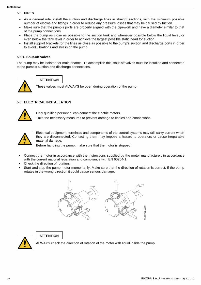
• Connect the motor in accordance with the instructions supplied by the motor manufacturer, in accordance with the current national legislation and compliance with EN 60204-1.
• Check the direction of rotation.
• Start and stop the pump motor momentarily. Make sure that the direction of rotation is correct. If the pump rotates in the wrong direction it could cause serious damage.
ALWAYS check the direction of rotation of the motor with liquid inside the pump.
ATTENTION
ATTENTION
01
.65
0.3
2.0
00
8
Start-up
INOXPA S.A.U. · 01.650.30.02EN · (B) 2021/10 11
6. Start-up
Prior to starting the pump, carefully read the instructions in section 5. Installation.
Carefully read section 9. Technical Specifications. INOXPA will not be liable for improper use of the equipment.
NEVER touch the pump or the lines if hot liquids are being pumped.
6.1. CHECKS BEFORE STARTING THE PUMP
• Completely open the shut-off valves on the suction and discharge lines.
• If liquid does not flow towards the pump, fill it with the liquid to be pumped.
The pump must never turn dry.
• Check that the power supply matches the rating indicated on the motor plate.
• Check that the direction of rotation of the motor is the right one.
6.2. CHECKS WHEN STARTING THE PUMP
• Check that the pump is not making any strange noises.
• Check if the absolute inlet pressure is sufficient to prevent cavitation in the pump. See the curve to determine the minimum pressure required above steam pressure (NPSHr).
• Control the discharge pressure.
• Check for leaks in the sealing areas.
Shut-off valves on the suction pipe must not be used to regulate the flow. All shut-off valves must be fully open during operation.
Control the motor consumption to prevent an electrical overload.
To reduce the flow and power consumed by the motor should reduce the motor speed.
A device that limits the pressure to 9,3 bar should be mounted to avoid that excess pressure damage the pump.
ATTENTION
ATTENTION
ATTENTION
Start-up
12 INOXPA S.A.U. · 01.650.30.02EN · (B) 2021/10
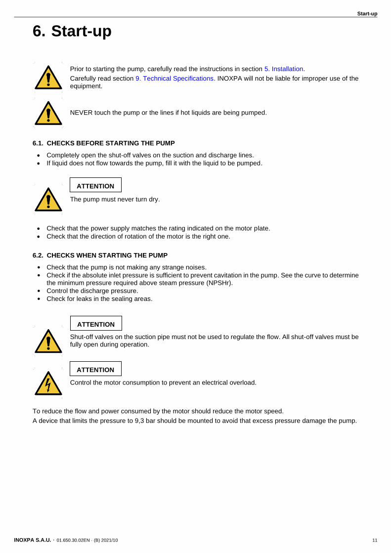
Use special protection when the sound pressure in the operation area exceeds 85 dB(A)
01
.65
0.3
2.0
00
9
Troubleshooting
INOXPA S.A.U. · 01.650.30.02EN · (B) 2021/10 13
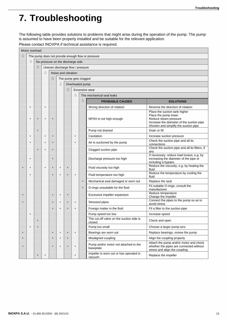
7. Troubleshooting
The following table provides solutions to problems that might arise during the operation of the pump. The pump is assumed to have been properly installed and be suitable for the relevant application.
Please contact INOXPA if technical assistance is required.
Motor overload
The pump does not provide enough flow or pressure
No pressure on the discharge side
Uneven discharge flow / pressure
Noise and vibration
The pump gets clogged
Overheated pump
Excessive wear
The mechanical seal leaks
PROBABLE CAUSES SOLUTIONS
• • Wrong direction of rotation Reverse the direction of rotation
• • • • NPSH is not high enough
Place the suction tank higher Place the pump lower Reduce steam pressure Increase the diameter of the suction pipe Shorten and simplify the suction pipe
• Pump not drained Drain or fill
• • • • Cavitation Increase suction pressure
• • • • Air is suctioned by the pump Check the suction pipe and all its connections
• • • Clogged suction pipe Check the suction pipe and all its filters, if any
• • Discharge pressure too high If necessary, reduce load losses, e.g. by increasing the diameter of the pipe or including a bypass.
• • • • • • Fluid viscosity too high Reduce the viscosity, e.g. by heating the fluid
• • • • • Fluid temperature too high Reduce the temperature by cooling the fluid
• Mechanical seal damaged or worn out Replace the seal
• O-rings unsuitable for the fluid Fit suitable O-rings, consult the manufacturer
• • • • Excessive impeller expansion Reduce temperature Change the impeller
• • • • • Stressed pipes Connect the pipes to the pump so as to avoid stress
• • • • Foreign matter in the fluid Fil a filter to the suction pipe
• Pump speed too low Increase speed
• The cut-off valve on the suction side is closed
Check and open
• • Pump too small Choose a larger pump size
• • • • • Bearings are worn out Replace bearings, review the pump
• • • • Misaligned coupling Align the coupling properly
• • • • • Pump and/or motor not attached to the baseplate
Attach the pump and/or motor and check whether the pipes are connected without stress and align the coupling
• • • Impeller is worn out or has operated in vacuum
Replace the impeller

Maintenance
14 INOXPA S.A.U. · 01.650.30.02EN · (B) 2021/10
8. Maintenance
8.1. GENERAL CONSIDERATIONS
This pump, just like any other machine, requires maintenance. The instructions contained in this manual cover the identification and replacement of spare parts. The instructions are aimed at maintenance personnel and those responsible for the supply of spare parts.
Carefully read chapter 9. Technical Specifications.
Maintenance work can only be carried out by qualified personnel that are trained and equipped with the necessary resources to carry out this work.
All parts or materials that are replaced must be properly disposed of/recycled in accordance with the current directives applicable in each area.
ALWAYS disconnect the pump before beginning any maintenance work.
8.2. CHECK THE MECHANICAL SEAL
Periodically check that there are no leaks around the shaft. If leakage is detected through the mechanical seal, replace it following the instructions in chapter 8.7. Disassembly and assembly of the pump.
8.3. TIGHTENING TORQUE
Size Nm lbf·ft
M6 10 7
M8 21 16
M10 42 31
M12 74 55
M16 112 83
8.4. STORAGE
Before being stored the pump must be completely emptied of liquids. Avoid, as far as possible, the exposure of the parts to excessively damp atmospheres.
8.5. BEARING MAINTENANCE
The bare shaft pump RF bearings are permanently greased bearings, so no lubrication maintenance is required. Under normal working duties, they must be changed after 15 000 working hours.
8.6. CLEANING
The use of aggressive cleaning products such as caustic soda and nitric acid may give to skin burns.
Use rubber gloves during cleaning procedures.
Always use protective goggles.
Maintenance
INOXPA S.A.U. · 01.650.30.02EN · (B) 2021/10 15
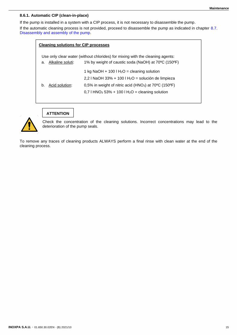
8.6.1. Automatic CIP (clean-in-place)
If the pump is installed in a system with a CIP process, it is not necessary to disassemble the pump.
If the automatic cleaning process is not provided, proceed to disassemble the pump as indicated in chapter 8.7. Disassembly and assembly of the pump.
Check the concentration of the cleaning solutions. Incorrect concentrations may lead to the deterioration of the pump seals.
To remove any traces of cleaning products ALWAYS perform a final rinse with clean water at the end of the cleaning process.
ATTENTION
Cleaning solutions for CIP processes
Use only clear water (without chlorides) for mixing with the cleaning agents:
a. Alkaline soluti: 1% by weight of caustic soda (NaOH) at 70ºC (150ºF) 1 kg NaOH + 100 l H2O = cleaning solution
2,2 l NaOH 33% + 100 l H2O = solución de limpieza
b. Acid solution: 0,5% in weight of nitric acid (HNO3) at 70ºC (150ºF)
0,7 l HNO3 53% + 100 l H2O = cleaning solution
Maintenance
16 INOXPA S.A.U. · 01.650.30.02EN · (B) 2021/10
8.7. DISASSEMBLY AND ASSEMBLY OF THE PUMP
The assembly and disassembly of the pumps should be done by qualified personnel. Make sure that the personnel read carefully this instruction manual and, in particular, those instructions which refer to the work they will perform.
Incorrect assembly or disassembly may cause damage in the pump’s operation and lead to high repair costs and a long period of downtime.
INOXPA is not responsible for accidents or damages caused by a failure to comply with the instructions in this manual.
Preparation
Provide for a clean working environment so some parts, including the mechanical seal, require very careful handling and others have close tolerances.
Check that the parts which are used are not damaged during transport. When doing this, you need to inspect the adjustment edge, the butted faces, the tight fit, burrs, etc.
After each disassembly, carefully clean the parts and check for any damage. Replace all damaged parts.
Tools
Use the proper tools for assembly and disassembly operations. Use them correctly.
Cleaning
Before disassembling the pump clean its external and inner part.
NEVER clean the pump by hand when it is running.
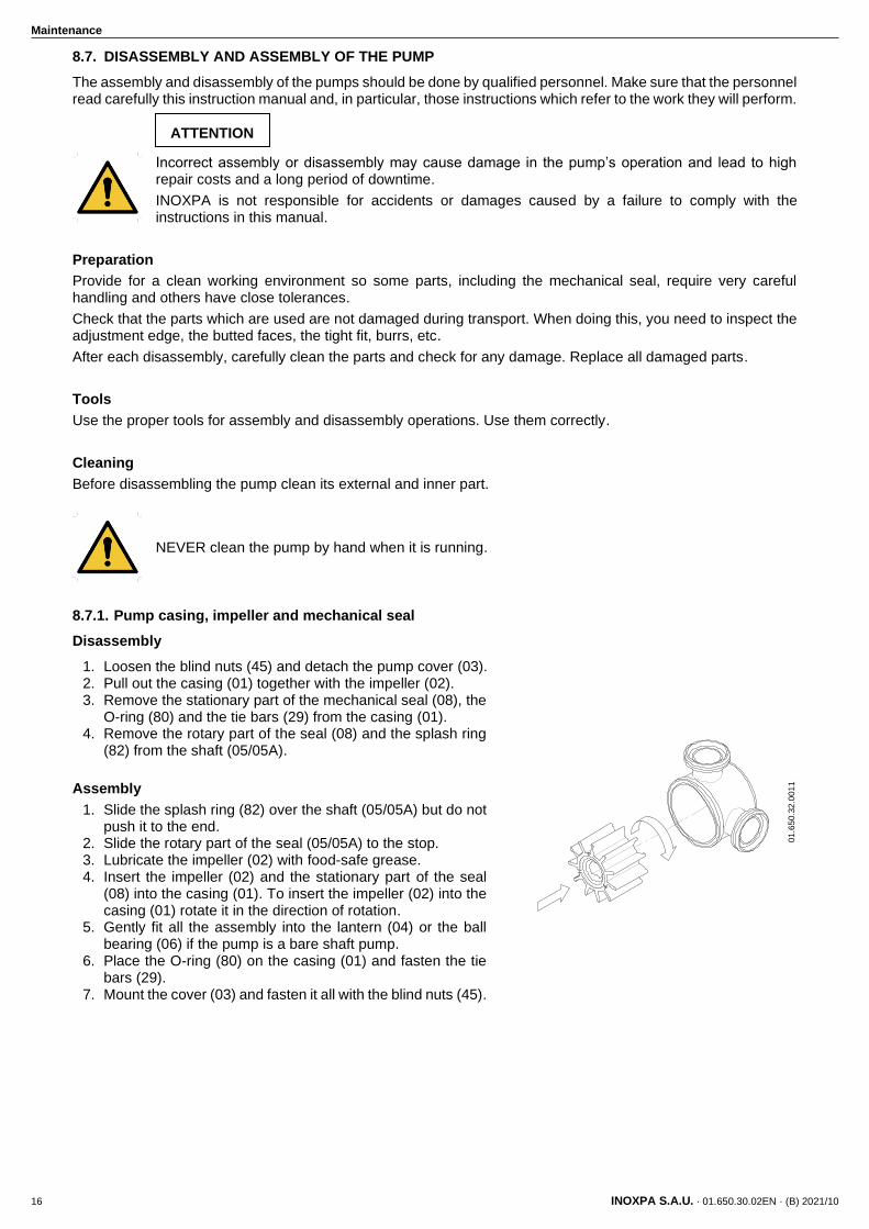
8.7.1. Pump casing, impeller and mechanical seal
Disassembly
1. Loosen the blind nuts (45) and detach the pump cover (03). 2. Pull out the casing (01) together with the impeller (02). 3. Remove the stationary part of the mechanical seal (08), the
O-ring (80) and the tie bars (29) from the casing (01). 4. Remove the rotary part of the seal (08) and the splash ring
(82) from the shaft (05/05A).
Assembly
1. Slide the splash ring (82) over the shaft (05/05A) but do not push it to the end.
2. Slide the rotary part of the seal (05/05A) to the stop. 3. Lubricate the impeller (02) with food-safe grease. 4. Insert the impeller (02) and the stationary part of the seal
(08) into the casing (01). To insert the impeller (02) into the casing (01) rotate it in the direction of rotation.
5. Gently fit all the assembly into the lantern (04) or the ball bearing (06) if the pump is a bare shaft pump.
6. Place the O-ring (80) on the casing (01) and fasten the tie bars (29).
7. Mount the cover (03) and fasten it all with the blind nuts (45).
ATTENTION
01
.65
0.3
2.0
01
1
Maintenance
INOXPA S.A.U. · 01.650.30.02EN · (B) 2021/10 17
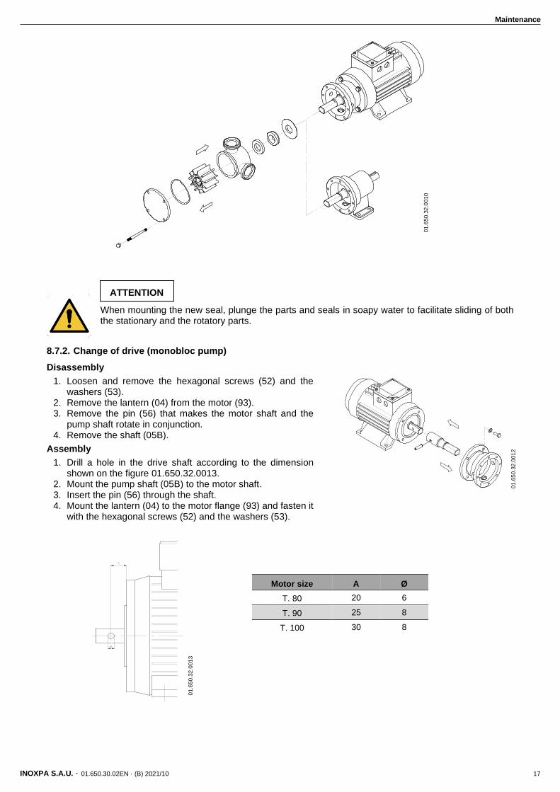
When mounting the new seal, plunge the parts and seals in soapy water to facilitate sliding of both the stationary and the rotatory parts.
8.7.2. Change of drive (monobloc pump)
Disassembly
1. Loosen and remove the hexagonal screws (52) and the washers (53).
2. Remove the lantern (04) from the motor (93). 3. Remove the pin (56) that makes the motor shaft and the
pump shaft rotate in conjunction. 4. Remove the shaft (05B).
Assembly
1. Drill a hole in the drive shaft according to the dimension shown on the figure 01.650.32.0013.
2. Mount the pump shaft (05B) to the motor shaft. 3. Insert the pin (56) through the shaft. 4. Mount the lantern (04) to the motor flange (93) and fasten it
with the hexagonal screws (52) and the washers (53).
Motor size A Ø
T. 80 20 6
T. 90 25 8
T. 100 30 8
ATTENTION
01
.65
0.3
2.0
01
0
01
.65
0.3
2.0
01
2
01
.65
0.3
2.0
01
3
Maintenance
18 INOXPA S.A.U. · 01.650.30.02EN · (B) 2021/10
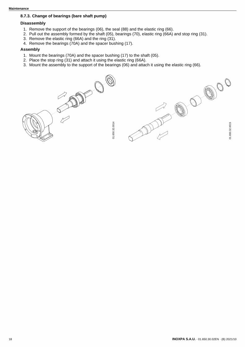
8.7.3. Change of bearings (bare shaft pump)
Disassembly
1. Remove the support of the bearings (06), the seal (88) and the elastic ring (66). 2. Pull out the assembly formed by the shaft (05), bearings (70), elastic ring (66A) and stop ring (31). 3. Remove the elastic ring (66A) and the ring (31). 4. Remove the bearings (70A) and the spacer bushing (17).
Assembly
1. Mount the bearings (70A) and the spacer bushing (17) to the shaft (05). 2. Place the stop ring (31) and attach it using the elastic ring (66A). 3. Mount the assembly to the support of the bearings (06) and attach it using the elastic ring (66).
01
.65
0.3
2.0
01
4
01
.65
0.3
2.0
01
5
Technical Specifications
INOXPA S.A.U. · 01.650.30.02EN · (B) 2021/10 19
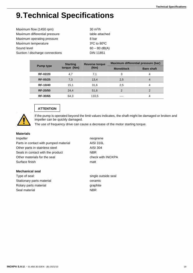
9. Technical Specifications
Maximum flow (1450 rpm) 30 m3/h
Maximum differential pressure table attached
Maximum operating pressure 8 bar
Maximum temperature 3ºC to 80ºC
Sound level 60 – 80 dB(A)
Suction / discharge connections DIN 11851
Pump type Starting
torque (Nm) Reverse torque
(Nm)
Maximum differential pressure (bar)
Monoblock Bare shaft
RF-02/20 4,7 7,1 3 4
RF-05/25 7,3 13,4 2,5 4
RF-10/40 15,1 31,6 2,5 4
RF-20/50 24,4 51,6 2 2
RF-30/65 64,3 110,5 ---- 4
If the pump is operated beyond the limit values indicates, the shaft might be damaged or broken and impeller can be quickly damaged.
The use of frequency drive can cause a decrease of the motor starting torque.
Materials
Impeller neoprene
Parts in contact with pumped material AISI 316L
Other parts in stainless steel AISI 304
Seals in contact with the product NBR
Other materials for the seal check with INOXPA
Surface finish matt
Mechanical seal
Type of seal: single outside seal
Stationary parts material ceramic
Rotary parts material graphite
Seal material NBR
ATTENTION
Technical Specifications
20 INOXPA S.A.U. · 01.650.30.02EN · (B) 2021/10
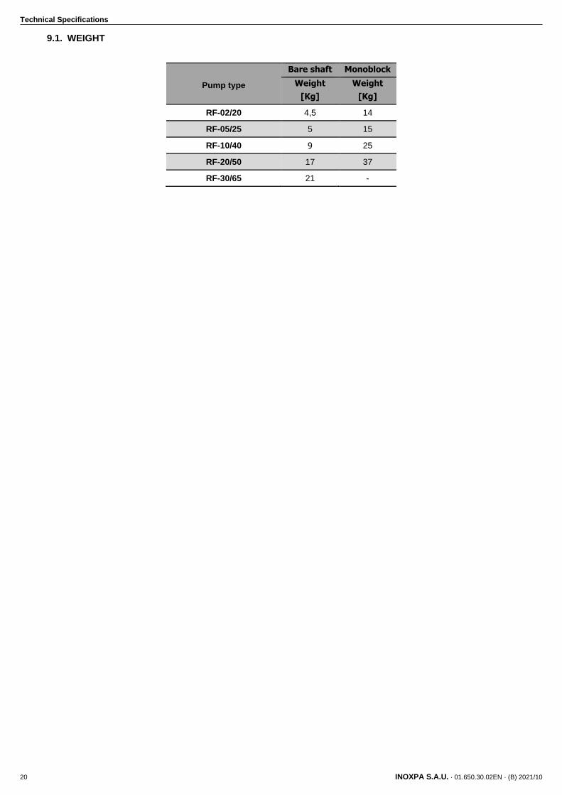
9.1. WEIGHT
Pump type
Bare shaft Monoblock
Weight
[Kg]
Weight
[Kg]
RF-02/20 4,5 14
RF-05/25 5 15
RF-10/40 9 25
RF-20/50 17 37
RF-30/65 21 -
Technical Specifications
INOXPA S.A.U. · 01.650.30.02EN · (B) 2021/10 21
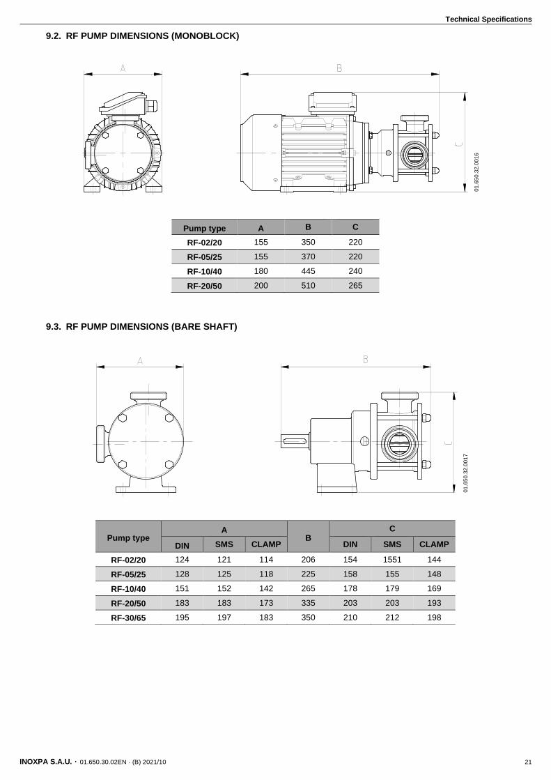
9.2. RF PUMP DIMENSIONS (MONOBLOCK)
9.3. RF PUMP DIMENSIONS (BARE SHAFT)
Pump type A B C
RF-02/20 155 350 220
RF-05/25 155 370 220
RF-10/40 180 445 240
RF-20/50 200 510 265
Pump type A
B C
DIN SMS CLAMP DIN SMS CLAMP
RF-02/20 124 121 114 206 154 1551 144
RF-05/25 128 125 118 225 158 155 148
RF-10/40 151 152 142 265 178 179 169
RF-20/50 183 183 173 335 203 203 193
RF-30/65 195 197 183 350 210 212 198
01
.65
0.3
2.0
01
6
01
.65
0.3
2.0
01
7
Technical Specifications
22 INOXPA S.A.U. · 01.650.30.02EN · (B) 2021/10
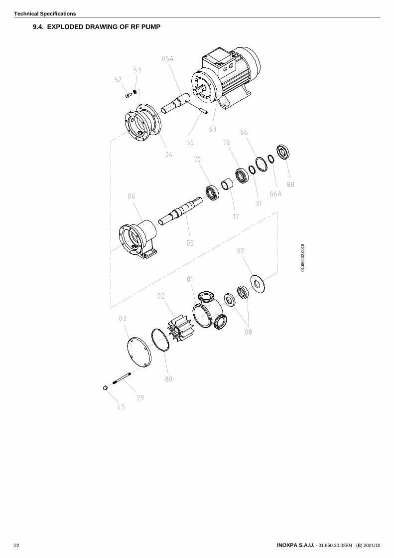
9.4. EXPLODED DRAWING OF RF PUMP
01
.65
0.3
2.0
01
9
Technical Specifications
INOXPA S.A.U. · 01.650.30.02EN · (B) 2021/10 23
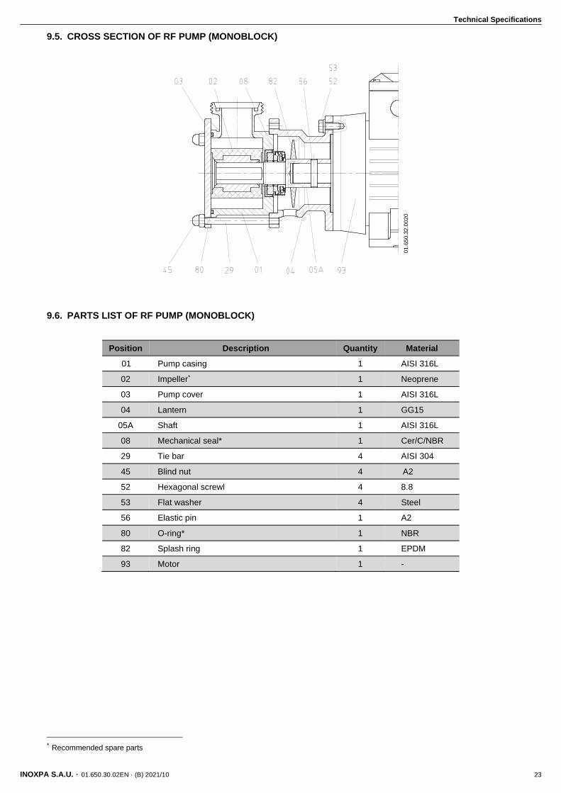
9.5. CROSS SECTION OF RF PUMP (MONOBLOCK)
9.6. PARTS LIST OF RF PUMP (MONOBLOCK)
Position Description Quantity Material
01 Pump casing 1 AISI 316L
02 Impeller* 1 Neoprene
03 Pump cover 1 AISI 316L
04 Lantern 1 GG15
05A Shaft 1 AISI 316L
08 Mechanical seal* 1 Cer/C/NBR
29 Tie bar 4 AISI 304
45 Blind nut 4 A2
52 Hexagonal screwl 4 8.8
53 Flat washer 4 Steel
56 Elastic pin 1 A2
80 O-ring* 1 NBR
82 Splash ring 1 EPDM
93 Motor 1 -
* Recommended spare parts
01
.65
0.3
2.0
02
0
Technical Specifications
24 INOXPA S.A.U. · 01.650.30.02EN · (B) 2021/10
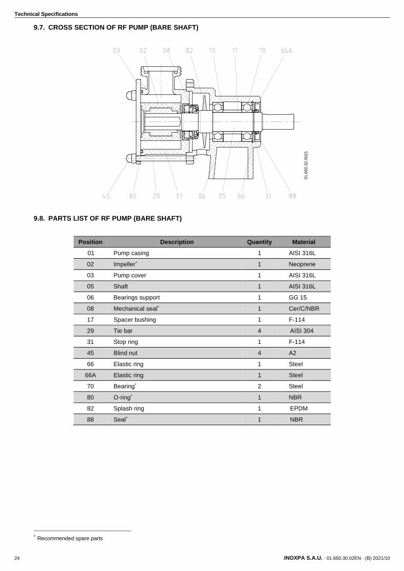
9.7. CROSS SECTION OF RF PUMP (BARE SHAFT)
9.8. PARTS LIST OF RF PUMP (BARE SHAFT)
Position Description Quantity Material
01 Pump casing 1 AISI 316L
02 Impeller* 1 Neoprene
03 Pump cover 1 AISI 316L
05 Shaft 1 AISI 316L
06 Bearings support 1 GG 15
08 Mechanical seal* 1 Cer/C/NBR
17 Spacer bushing 1 F-114
29 Tie bar 4 AISI 304
31 Stop ring 1 F-114
45 Blind nut 4 A2
66 Elastic ring 1 Steel
66A Elastic ring 1 Steel
70 Bearing* 2 Steel
80 O-ring* 1 NBR
82 Splash ring 1 EPDM
88 Seal* 1 NBR
* Recommended spare parts
01
.65
0.3
2.0
02
1

NOTES
________________________________________________________________________________
________________________________________________________________________________
________________________________________________________________________________
________________________________________________________________________________
________________________________________________________________________________
________________________________________________________________________________
________________________________________________________________________________
________________________________________________________________________________
________________________________________________________________________________
________________________________________________________________________________
________________________________________________________________________________
________________________________________________________________________________
________________________________________________________________________________
________________________________________________________________________________
________________________________________________________________________________
________________________________________________________________________________
________________________________________________________________________________
________________________________________________________________________________
________________________________________________________________________________
________________________________________________________________________________
________________________________________________________________________________
________________________________________________________________________________
________________________________________________________________________________
________________________________________________________________________________
________________________________________________________________________________
________________________________________________________________________________
________________________________________________________________________________
________________________________________________________________________________
________________________________________________________________________________
________________________________________________________________________________

INOXPA S.A.U.
Telers, 60 – 17820 – Banyoles – Spain
Tel.: +34 972 575 200 – Fax.: +34 972 575 502
How to contact INOXPA S.A.U.:
Contact details for all countries are
Continually updated on our website.
Please visit www.inoxpa.com to access the information.
01.6
50.3
0.0
2E
N (
B)
2021/1
0