Temper: Hard Diameter Thickness Tolerance: +15% Diameter ...
60
Diameter 42mm Temper: Hard Max Working Pressure: 35 Thickness Tolerance: +15% Diameter Tolerance: +0.06mm Wall 1.0mm 10th Revision 2015
Transcript of Temper: Hard Diameter Thickness Tolerance: +15% Diameter ...

Lawton Tube Technical Guide - 10th Revision 2015
Diameter42mm
Temper: HardMax Working Pressure: 35Thickness Tolerance: +15%Diameter Tolerance: +0.06mm
Wall1.0mm
10th Revision 2015

Lawton Tube Technical Guide - 10th Revision 2015
‘Maintaining a policy of continual product development, The Lawton Tube Co Ltd reserves the right to change specifications, design and materials of products listed in this publication without prior notice.’
2
Contents Company Profile 03
Company Structure 04 Quality Policy 05
Product Specifications/Technical Information
Engineering Copper Tubes 06
Plumbing Copper Tubes 07
Plumbing Fittings 11
Plumbing Accessories 19
Medical Gas Tubes 24
Medical Gas Metric Endfeed Fittings 26
Brazing Rods 32
Refrigeration and Air Conditioning Tubes 33
ACR Fittings 35
Brazing Rods 42
Lawton Dual 43
Lawton K65 45
Approvals
Kitemark – BS EN 1057 copper tubes 47
CE Mark Cert - EN 1057 copper tubes 48
Kitemark – IS EN 1057 copper tubes 49
Kitemark – BS EN13348 copper tubes 49
Water Regulations Advisory Scheme 50
Quality System ISO 9001:2008 51
Affiliation Certificates 51
25 & 30 Year Guarantee 52
COSHH - Hazard Data Sheet 53
Company Environmental Policy 54
Health & Safety Policy 54
Standard Conditions of Sales 56

Lawton Tube Technical Guide - 10th Revision 2015
Company Profile Established in 1917 and based in Coventry, The Lawton Tube Company is the UK’s largest independent
copper tube maker. The Company is a Private Limited Company without any group associations with the
freedom necessary to satisfy customer requirements and respond to product and process changes with the
latest technical requirements.
We offer a wide range of quality assured copper tubes, complying with the latest specifications, to both
the construction and engineering markets. Lawton Tube is able to supply a range of standard products
or special one off orders. Plant developments and installations have kept pace with market demands for
a high integrity product and employ the latest manufacturing techniques. A fully integrated production
system based on high speed block drawing and semi automated benches form the core of our primary
processing. From initial extrusion to finished tube, Lawton Tube ensures that diameter, thickness, temper
and length are all controlled within predetermined limits with the most up-to date manufacturing and
inspection standards.
Lawton Tube has been assessed and registered as a BSI Approved Company operating Quality Systems
to meet the requirements of BS EN ISO 9001-2008 and qualifies for the KITEMARK EN 1057 (plumbing)
and EN 13348 (medical). Lawton Tube was the first company in the United Kingdom to have the EN 13348
(medical) KITEMARK. From receipt of certified raw materials to final inspection and despatch the aim is to
manufacture a tube fit for purpose.
During 2001, Lawton Tube acquired Dorset Tube in Poole, which added to the breadth of Engineering tube
supplied by the Coventry unit and included the production of cupro-nickel brake pipe tube. Dorset Tube has
been assessed and registered as a BSI Approved Company and are operating Quality Systems to meet the
requirements of BS EN ISO 9001-2008.
3

Lawton Tube Technical Guide - 10th Revision 2015
Company Structure
Giles LawtonManaging Director
(Operations)
Tony WatsonOperations Manager
Steve WilsonBuilding Services
Jo BoyleOperations Assistant
Operations Department
Accounts Department
Simon WaldronFinance Director
Company Secretary
Georgina AlbrightonAdministrator
Alison StansbieAssistant
Accountant
Donna KingCredit Controller
Robert LawtonBusiness
Development Director
Oliver LawtonManaging Director
(Commercial)
Lee ClaytonHead of P & H
Priya KaravadraAccounts
David RebeiroBusiness
Development Executive
Chris WhiteHead of ACR
Adam PughKey Account
Manager
Terrie EvansAccount Manager
Emma McCusker
Sales Co-ordinator
Satvinder Bhachu
Quality Controller
Sales Department
Mark GaleTransport Manager
Drivers
Mark DanksFirst Shift Supervisor
First Shift
Hartmond BurgundySecond Shift
Manager
Second Shift
Jon BrealeyACR Distribution
Manager
ACR Operators
Alan ClarkeProduction Supervisor
Production Operators
4
Abbie Faulkner
Sales Co-ordinator

Lawton Tube Technical Guide - 10th Revision 2015
Quality Policy Lawton Tube Company is committed to maintain, on a continuous basis, an effectively Quality Management System, which complies with the requirements of the BS EN ISO 9001:2008 System for Quality Management.
The QMS is a framework guiding Lawton Tube Management and Employees to focus on identifying and meeting customer requirements consistently in an environment in which people understand, and are fully involved in achieving the business objectives through effective communication and leadership.
Lawton Tube is committed to complying with the requirements of the QMS and continually improving its effectiveness.
Lawton Tube is committed to continually improve on the organisational performance, making use of appropriate decision making tools to establish, analyse and improve through monitoring of agreed quality objectives.
Lawton Tube is committed to ensuring that resources required for the QMS processes are provided, adequately maintained and improved in order to meet customer’s requirements.
In the interest of complying with customer requirements, Lawton Tube will enter into, and develop mutually beneficial relationships with suppliers of services and goods where deemed appropriate.
Lawton Tube will make arrangements to comply with current statutory and regulatory requirements including Health and Safety Legislation.
The Company is committed to the Quality Management System Procedures stated in this Manual and all employees are responsible for meeting the requirements laid down.
The Operations Manager is authorised to control and ensure the system is maintained. In the event of a major problem, which could have an adverse effect on the operation of the Quality System, this should be brought to the attention of the joint Managing Directors for resolution.
Trade Bodies Lawton Tube are proud to be associated and support the following
5

Lawton Tube Technical Guide - 10th Revision 2015
Engineering Copper Tubes Pipeline solutions for Engineering applications.
Made to order so contact our Sales department with FULL enquiry. Average manufacturing time is 4 weeks. We manufacture/distribute to the following European Specifications (American ASTM can also be offered):BS EN 12449:1999 BS EN 12541:1999 BS EN 13600:2002
BS EN 12449 Seamless, round tubes for general purposes. Material Analysis (C106) Material Grade Phosphorus de-oxidised copper; Cu-DHP or CW024A as defined in BS EN 1976. Minimum Copper Content 99.90 % (including silver) Phosphorus 0.015-0.040 % Total Impurity Maxima 0.060 % (excluding phosphorus and silver)
Mechanical Properties
BS EN 12451 Seamless, round tubes for heat exchangers Material Analysis Material Grade Phosphorus de-oxidised copper; Cu-DHP or CW024A as defined in BS EN 1976. Minimum Copper Content 99.90 % (including silver) Phosphorus 0.015-0.040 % Total Impurity Maxima 0.060 % (excluding phosphorus and silver)
Mechanical Properties
BS EN 13600 Seamless, round tubes for electrical purposes Material Analysis (HC C101) Material Grade Phosphorus de-oxidised copper; Cu-ETP or CW004A as defined in BS EN 1976. Minimum Copper Content min 99.90 % (including silver) Max Oxygen – 0.060 % is permitted, subject to agreement between the purchaser and Lawton Tubes Max Lead – 0.005 % Total Impurity Maxima 0.030 % (excluding oxygen, lead and silver)
Material Analysis (HC C103) Material Grade Phosphorus de-oxidised copper; Cu-OF or CW008A as defined in BS EN 1976. Minimum Copper Content min 99.95 % (including silver) Max Lead – 0.005 % Total Impurity Maxima 0.030 % (excluding lead and silver)
Mechanical Properties
Material Temper
R250 (Half Hard) R290 (Hard)
Hardness (Indicative) HV5 VPN
75-100 Over 100
Elongation min.(%)
20 5
Tensile Strength min. (N/mm2)
250 290
BS EN 12451 Seamless, round tubes for heat exchangers
Material Temper
R200 (soft) R250 (Half Hard)
R290 (Hard)
Hardness (Indicative) HV5 VPN
40-65 70-100 95-120
Elongation min.(%)
40 20 5
Tensile Strength min. (N/mm2)
200 250 290
BS EN 12449 Seamless, round tubes for general purposes
Material Temper
R200 (soft) R250 (Half Hard)
R290 (Hard)
Hardness (Indicative) HV5 VPN
35-65 65-95 90-110
Elongation min.(%)
40 15 5
Tensile Strength min. (N/mm2)
200 250 290
BS EN 13600 Seamless, round tubes for electrical purposes
6
Lawton Tube Technical Guide - 10th Revision 2015
Plumbing Copper Tubes BS EN 1057
Material Analysis Material Grade Phosphorus de-oxidised copper; Cu-DHP or CW024A as defined in BS EN 1976. Minimum Copper Content 99.90 % (including silver) Phosphorus 0.015-0.040 % Total Impurity Maxima 0.060 % (excluding phosphorus and silver) The melting point of copper is 1083ºC and it has a density of 8.9 gm/cc
Packaging All tubes are bundle tied, 15-28mm (TX) are Yellow end capped in tubes of 10 (UK market only).
Marking Sizes 15 - 54mm copper tubes are stamped with: · Tube size · Kitemark · EN 1057 · Temper · Manufacturer · Date (quarter) Sizes 67mm and above are stamped at either end of the tube.
7

Lawton Tube Technical Guide - 10th Revision 2015
Dimensions and Tolerances (includes chrome plated and PVC covered)
Working pressures are to BS 2871:part1:1971
8
Mechanical Properties BS EN 1057 Plumbing Copper Tubes
Temper
Half Hard Soft
Half Hard Half Hard
Soft Half Hard Half Hard
Soft Half Hard Half Hard Half Hard Half Hard Half Hard
Soft Half Hard Half Hard
Soft Half Hard Half Hard
Hard Half Hard
Hard Hard
Half Hard Hard Hard
Half Hard Hard Hard Hard Hard Hard Hard Hard Hard Hard Hard
Wall (mm)
0.6 (TX) 0.6
0.8 (TY) 0.6 (TX)
0.6 0.8 (TY) 0.6 (TX) 0.7 (TY) 0.8 (TY) 0.6 (TX) 0.8 (TY) 0.7 (TX) 1.0 (TY) 1.0 (TY) 0.9 (TX) 1.2 (TY) 1.2 (TY) 0.9 (TX) 1.2 (TY)
1.0 (LiteX) 1.2 (TX) 1.5 (TY)
1.0 (LiteX) 1.2 (TX) 1.5 (TY)
1.2 (LiteX) 1.2 (TX) 1.5 (TY) 1.2 (TX) 2.0 (TY) 1.5 (TX) 2.0 (TY) 1.5 (TX) 2.5 (TY) 1.5 (TX) 2.0 (TX) 3.0 (TX)
O.D. (mm)
6 6 6 8 8 8 10 10 10 12 12 15 15 15 22 22 22 28 28 35 35 35 42 42 42 54 54 54
66.7 66.7 76.1 76.1 108 108 133 159 219
Diameter Tolerance Mean Including Ovality
± 0.04mm ±0.09mm ± 0.04mm Not applicable ± 0.04mm ±0.09mm ± 0.04mm ±0.09mm ± 0.04mm Not applicable ± 0.04mm ±0.09mm ± 0.04mm ±0.09mm ± 0.04mm Not applicable ± 0.04mm ±0.09mm ± 0.04mm ±0.09mm ± 0.04mm ±0.09mm ± 0.04mm ±0.09mm ± 0.04mm ±0.09mm ± 0.04mm Not applicable ± 0.05mm ±0.10mm ± 0.05mm ±0.10mm ± 0.05mm Not applicable ± 0.05mm ±0.10mm ± 0.05mm ±0.10mm ± 0.06mm ±0.07mm ± 0.06mm ±0.11mm ± 0.06mm ±0.07mm ± 0.06mm ±0.07mm ± 0.06mm ±0.11mm ± 0.06mm ±0.07mm ± 0.06mm ±0.07mm ± 0.06mm ±0.11mm ± 0.06mm ±0.07mm ± 0.07mm ±0.10mm ± 0.07mm ±0.10mm ± 0.07mm ±0.10mm ± 0.07mm ±0.10mm ± 0.07mm ±0.20mm ± 0.07mm ±0.20mm ± 0.20mm ±0.70mm ± 0.20mm ±0.70mm ± 0.60mm ±1.50mm
Thickness Tolerance
±10% ±10% ±10% ±10% ±10% ±10% ±10% ±10% ±10% ±10% ±10% ±10% ±13% ±13% ±10% ±15% ±15% ±10% ±15% ±15% ±10% ±10% ±15% ±10% ±10% ±15% ±10% ±10% ±15% ±15% ±15% ±15% ±15% ±15% ±15% ±15% ±15%
Max Working Pressure bar up to 65oC
133 90
188 97 66 136 77 62
106 63 87 58 87 67 51 69 57 40 55 42 42 64 35 35 53 33 27 55 26 45 29 39 20 34 16 18 20
Material Temper EN 1173
R200 (soft) R250 (Half Hard)
R290 (Hard)
Hardness (Indicative) HV5 VPN
40-70 75-100
Over 100
Elongation min.(%)
40 30 (TX) 20 (TY)
3
Tensile Strength min. (N/mm2)
220 250 290

Lawton Tube Technical Guide - 10th Revision 2015
10° 0.5mm 0.7mm 0.9mm 1.0mm 1.2mm 1.4mm 1.5mm 1.7mm 2.0mm 4.3mm 20° 1.0mm 1.4mm 1.7mm 2.0mm 2.4mm 2.7mm 3.0mm 3.4mm 4.0mm 8.5mm 30° 1.5mm 2.0mm 2.6mm 3.1mm 3.6mm 4.1mm 4.6mm 5.1mm 6.1mm 13.0mm 40° 2.0mm 2.7mm 3.4mm 4.1mm 4.8mm 5.4mm 6.1mm 6.8mm 8.2mm 17.0mm 50° 2.6mm 3.4mm 4.3mm 5.1mm 6.0mm 6.8mm 7.7mm 8.5mm 10.2mm 21.0mm 60° 3.1mm 4.1mm 5.1mm 6.1mm 7.1mm 8.2mm 9.2mm 10.2mm 12.2mm 26.0mm 70° 3.6mm 4.8mm 6.0mm 7.1mm 8.3mm 9.5mm 10.7mm 11.9mm 14.3mm 30.0mm 80° 4.1mm 5.4mm 6.8mm 8.2mm 9.5mm 10.9mm 12.2mm 13.6mm 16.3mm 34.0mm 90° 4.6mm 6.1mm 7.7mm 9.2mm 10.7mm 12.2mm 13.8mm 15.3mm 18.4mm 38.0mm 100° 5.1mm 6.8mm 8.5mm 10.2mm 11.9mm 13.6mm 15.3mm 17.0mm 20.4mm 43.0mm 150° 7.65mm 10.2mm 12.75mm 15.3mm 17.85mm 20.4mm 22.95mm 25.5mm 30.6mm 63.75mm 200° 10.2mm 13.6mm 17.0mm 20.4mm 23.8mm 27.2mm 30.6mm 34.0mm 40.8mm 85.0mm
Temperature Tube length change 3m 4m 5m 6m 7m 8m 9m 10m 12m 25m
O/D Capacity mm kg/m
O/D Capacity mm kg/m
O/D Capacity mm kg/m
6 0.0169 8 0.0347 10 0.0558
6 0.0169 8 0.0347 10 0.0615 12 0.0890 15 0.1416 18 0.2063 22 0.3140 28 0.5308 35 0.8220 42 1.2163 54 2.0712 67 3.2134 76 4.1699 108 8.6107 133 13.2647 159 18.8351
6 0.0139 8 0.0302 10 0.0529 12 0.0818 15 0.1280 18 0.1952 22 0.2943 28 0.5050 35 0.7888 42 1.1758 54 1.9317 67 3.2375 76 4.0438 108 8.2527
Copper Tube Expansion
Table W Microbore
Water Capacity
Table X 6mm - 159mm Table Y 6mm - 108mm
Expansion of copper tubeCopper has a coefficient of linear expansion of 17 x 10-6oC. for example, a 10 metre length of copper tube carrying hot water at 600C will increase in length by almost 7mm when heated from 200C. Assuming that temperature cycling of the system is 200C, thaere will be a continuous cycle of expansion and contration of 3.4mm.refer to table below.
9

Lawton Tube Technical Guide - 10th Revision 2015
Make circular incision in plastic cover
Secure the spliced plastic cover with tape
Wrap exposed plastic with a damp cloth
The finished joint
Remove the cut plastic from the end of the tube
Clean tube and fitting with a suitable abrasive pad
Heat with blow lamp
Exposed ends should be sealed with tape
Make the incision in plastic along tube
Apply Flux
When cooled remove damp cloth and re-position plastic
Peel back the plastic cover carefully
Connect tube and fitting
Secure with tape
Plastic Coated Copper Tube Installation Guide
1
5
9
13
2
6
10
14
3
7
11
4
8
12
10

Lawton Tube Technical Guide - 10th Revision 2015
Installation Instructions for plastic coated tubeFor both capillary and compression fittings the tube should be cut with a pipe cutter or with a fine tooth hacksaw and deburred inside and outside.
When using capillary fittings, the plastics cover should be cut lengthways and folded back about 100mm and care should be taken not to allow the flame of the torch or blowlamp to come into contact with the covering. It is recommended that the end of the plastic and part of the exposed copper be wrapped with a wet rag, to prevent over-heating and damage of the cover. The use of excess flux should be avoided and any residual flux should be removed to prevent unsightly stains or in extreme cases corrosion of the pipework.When using compression fittings, the plastics cover should be cut and removed sufficiently to permit entry of the copper tube through the coupling nut and up to the tube stop in the body of the fitting and where appropriate for the tube end to be flared.
When joints are complete it is essential that any cut and folded plastics are returned to their original position and the lengthways cut and any exposed pipework and fitting are carefully and completely protected by spirally taping the joint with self-adhesive polyethylene or PVC waterproof tape.
Moisture should be prevented from entering the channels in plastics coverings at positions where the covering has been terminated. This can be achieved by the application of a suitable waterproof adhesive plastic tape over the last 25mm or so of plastics covering and a similar length of immediately adjacent bare copper tube.
When using ‘O’ ring seal fittings, such as in push-fit or press-fit fittings, care must be taken when removing the plastics covering not to create a lengthways score mark on the copper where the fitting will be placed. Such a score could prevent the ‘O’ ring from making a complete seal. The plastics cover should be cut and removed sufficiently to permit entry of the copper tube up to the tube stop in the body of the fitting. When joints are complete it is essential that any cut and folded plastics are returned to their original position and the lengthways cut and any exposed pipework and fitting are carefully and completely protected by spirally taping the joint with self-adhesive polyethylene or PVC waterproof tape. Before jointing soft temper tubing with fittings it is essential that a re-rounding tool be used.
Installation of plastic covered tubeExperienced, time-served, plumbers are familiar with the installation of copper tube systemssince they have been used for very many years and are considered the standard materialagainst which all others are measured. The plastic coated products areincreasing in use and some comments on their installation follow.Plastic coated tubes are Lawton copper tubes sheathed in a continuous plastics cover.The covering on it has air channels on its internal surface. Although plastic coated tubes are primarily designed for protection against external aggressive materials, the cover creates a thermal barrier that reduces heat loss from buried hot service tube and condensation along surface fixed cold service pipework. Plastic coated tubes are particularly recommended for domestic hot water and heating services, especially if the pipes are to be buried in plaster or screed, or for cold water services exposed to conditions of high humidity where condensation may be a problem.Plastic coated tubes are primarily intended for internal / underground applications and outdoor surface fixing of these products is therefore not recommended.
Maintaining the ProtectionTo maintain protection any breach made in the plastic cover must be made good to ensure the protective properties are maintained. To maintain a continuous protective coating where the plastics cover has been cut back exposing the copper, for making joints for instance, the bare copper tube (and fitting) should be carefully and completely wrapped with an adhesive polythene or PVC waterproof tape: see Installation Instructions 3.1.5. Moisture should be prevented from entering the channels in the plastics coating where it has been terminated, breached or

Lawton Tube Technical Guide - 10th Revision 2015
damaged. The best way to do this is by the spiral, overlapping application of a suitable waterproof adhesive plastics tape over at least the last 25mm of intact plastics covering and at least a similar length of immediately adjacent bare copper pipe.
Taking Care of Expansion and ContractionFor the relatively short tube runs encountered in domestic installations, thermal expansion and contraction is normally accommodated by bends, elbows, off-sets, etc. and no special precautions are generally required. However, on longer straight tube runs (usually in excess of 10 metres) consideration should be given to the use of expansion devices such as expansion bellows or loops.Where burying in concrete is allowed, Plastic coated tube helps to take care of thermal expansion andcontraction.Where pipework carrying hot water is buried in concrete, precautions need to be taken to protect thetubing from both external corrosion and the effects of thermal movement. In such circumstancesPlastic coated tube, by virtue of the air channels formed on the inside surface of the plastics coating, notonly provides external protection and a degree of thermal insulation but also, when laid in the mannerrecommended, has a greater ability to absorb the stresses imposed by thermal movement.
The coefficient of linear expansion of copper is 16.8 x 10⁻⁶ per ºC. This means, for example, that a10m length of copper tube, irrespective of diameter, thickness or temper, will increase in length by10.2mm when its temperature is increased by 60ºC (a typical value for a central heating system). Oncooling down, the tube will contract to its original length. If this thermal movement is not allowed for indesign and installation, considerable cyclic stress will be imposed on the tubing and/or associatedfittings. These stresses can lead to either premature failure of the joint (i.e. a so-called “pulled joint”)or fatigue failure of the tube itself. To avoid this, ideally fittings should not be buried in concrete.Clearly, if firmly buried in screed the branch of a tee will become a fixed point and this situationshould be avoided wherever possible. If burying the system in concrete is unavoidable, however, anyjoints such as tees, elbows, etc., should be installed so that they are free to move when the pipeworksystem expands and contracts. For example, a tee joint and approximately one metre of its branchshould be laid in a duct filled with a material that will “give” (e.g. vermiculite) and covered with a ductcover. This will normally be sufficient to absorb the stresses imposed on the branch.When soft coiled tubing is properly installed, in a serpentine (snake-like) manner, thecopper tube is free to move within the castellated plastics sleeve. When in concrete, the plasticssleeve is fixed in position but tube movement from expansion and contraction is accommodatedwithin channels of the sleeve.
When installing the tube in a serpentine manner, it is usefulto regard each segment of the “snake” as an arc in whicheach change of direction can then accommodate about 1mmof expansion. Thus, as a guide, we would recommend thatthe “wavelength” of the “snake” should be no more thanabout two metres, i.e. one metre between the “nodes”. Theminimum displacement of a “snaked” tube line isconsidered to be one full diameter of the pipe sizeconcerned, although more commonly two to three diametersis the distance used.
At corners of a buried installation, a bend should be put in the tube, rather than an elbow fitting. Asmooth bend, of generous radius, is better able to absorb stresses than a bend of tight radius buteither is preferable to an elbow, which becomes an anchor point only slightly less rigid than a tee.Similarly, where the tubing leaves the screed to connect to radiators etc., a bend of generous radiusis preferred. The plastics sleeve should be continued almost up to the radiator connection since, if itis cut back to floor level, there is a risk that concrete will adhere to the bare copper tube and createan anchor point.

Lawton Tube Technical Guide - 10th Revision 2015
Burying in Plaster, Screed and ConcreteSoft temper (R220) copper tubing, made to the requirements of BS EN 1057, is the preferred materialfor this type of application. This pipework is supplied in long length coils and generally does not needfittings under screed. Such tubing is available in 8 to 22mm sizes.Where pipework is fitted within ducted systems, i.e. where the pipework is surrounded by air and notdirectly embedded in concrete, Yorkex straight length material, to BS EN 1057 R250 / R290 can beused. Indeed, in such a system the pipework is free to move in the surrounding air space andtherefore acts in a manner similar to surface-fixed tubing. However, some construction materials maycontain contaminants, which are aggressive to copper; we do not therefore recommend that barecopper tubing be embedded directly into concrete or plaster. Instead, tubing fixed in such locationsshould be protected by a factory-applied plastics covering such as that provided by Lawton Plastic covered tube. It should also be borne in mind that the minimum recommended depth to which plastics coatedpipework should be buried in screed or plaster is 50mm, measuring from the top of the tube in situ.For tubing embedded in plaster, this may require chasing the pipework into the wall.Before going ahead with any design or installation work, it is recommended that the view of the localwater supplier on the subject of “accessibility of pipework” is established since the interpretation andapplication of the water supplier regulations may vary from region to region.
Good PracticeDuring installation, it is suggested that the end of the tube be nipped or covered to prevent dust or dirtentering. A further tip when tube is used for a central heating system is to mark withcoloured tape or pencil the flow and return tubes so that at the manifold and radiator valveconnections, there is a clear indication which pipes carry the flow and which the return. This isparticularly useful where solid floors are to be laid.
Flushing and Avoidance of StagnationBS 6700(2), Section 3.1.10.1 states that; “every new water service, cistern, distributing pipe, hot watercylinder, or other appliance and any extension or modification to such a service shall be thoroughlyflushed with drinking water before being taken into use”All water services/heating systems should be thoroughly flushed with clean water as soon aspossible after completion to remove foreign matter including filings, flux residues etc. Flushingshould continue until the discharge water is completely clear. It should be borne in mind that simplyfilling a system and then draining down does not constitute a flush and, in most cases, will servemerely to move extraneous matter from one point in the pipework installation to another.Ideally, new/modified systems should be brought into use immediately after flushing and not leftcharged with stagnant water. If it is not possible to bring the system into immediate use then itshould be completely drained down. If this is for an extended period then disinfection may berequired (see Section 3.3.)It is, in practice, notoriously difficult to effect a 100% drain down of an installation particularly wherelong, horizontal tube runs are involved. Instead, it is recommended, for the purpose on minimizingthe risk of pipework deterioration and/or water quality problems, that the systems be left fully chargedand flushed through at regular intervals. The system should be flushed, at a frequency of no lessthan twice per week, by opening all outlets for a period that is long enough to completely rechargethe system with fresh water. This practice should continue until such time as the system is broughtinto regular use. Under certain circumstances, consideration should also be given to frost protection.Reference to the need to avoid stagnation in pipework is made in various publications including aHSE publication(1) which provides information on how to prevent the development of legionellabacteria.Certain systems will require to be disinfected, prior to bringing into use, to comply with therequirements of BS 6700(2).

Service Temperature***
Service Temperature**
Service Temperature*
Max 1100C
16 bar 10 bar 10 bar
650C
25 bar 16 bar 16 bar
300C
25 bar 25 bar 16 bar
Size
8mm to 28mm 35mm to 54mm 67mm
Min -400C
25 bar 25 bar 16 bar
Size
8mm 10mm 12mm 15mm 22mm 28mm 35mm 42mm 54mm
650C
62.5 bar 50.9 bar 42.9 bar 40.3 bar 35.6 bar 28.2 bar 25.2 bar 23.2 bar 19.8 bar
Min -1960C
62.5 bar 50.9 bar 42.9 bar 40.3 bar 35.6 bar 28.2 bar 25.2 bar 23.2 bar 19.8 bar
1200C
58.8 bar 47.9 bar 40.3 bar 37.9 bar 33.5 bar 26.5 bar 23.7 bar 21.8 bar 18.6 bar
1500C
46.7 bar 38.0 bar 32.0 bar 30.1 bar 26.6 bar 21.1 bar 18.8 bar 17.3 bar 14.7 bar
1750C
35.5 bar 28.9 bar 24.3 bar 22.8 bar 20.2 bar 16.0 bar 14.3 bar 13.1 bar 11.2 bar
Max 2000C
23.3 bar 19.0 bar 16.0 bar 15.0 bar 13.3 bar 10.5 bar 9.4 bar 8.6 bar 7.4 bar
Size
67mm 76mm 108mm 133mm 159mm
650C
18.6 bar 18.6 bar 17.2 bar 10.5 bar 11.7 bar
Min -1960C
18.6 bar 18.6 bar 17.2 bar 10.5 bar 11.7 bar
1200C
17.5 bar 17.5 bar 16.2 bar 8.5 bar 9.7 bar
1500C
14.0 bar 14.0 bar 12.9 bar 7.7 bar 8.6 bar
Max 2000C
6.9 bar 6.9 bar 6.4 bar 4.1 bar 4.6 bar
Lawton Tube Technical Guide - 10th Revision 2015
Plumbing Metric Endfeed Fittings Copper end feed type fittings manufactured to: BS EN 1254-1:1998 Part 1 Specification for copper and copper alloy fittings with capillary ends for soldering and brazing for use with copper tubes. BS EN 1254-1:1998 Part 5 Specification for copper and copper alloy fittings with short ends for capillary brazing for use with copper tubes. 35mm plus size fittings are supplied in individually sealed protective polythene bags and are specifically designed for copper systems.
Specific Benefits Include: Lawton tube endfeed fittings are guaranteed against manufacturing defects for 25 years. All fittings supplied contain less than 100mg/m2 (0.01mg/cm2) of hydrocarbons on the degreased surface. Each fitting is engraved with unique branding together with the EN spec and fitting size where space permits. All sealed in protective polythene bags and are product labelled. Fittings are supplied in reinforced cardboard boxes, labelled with product information and outline drawing of fitting.Each fitting is engraved with unique branding, space permitting
11
Working Temperatures and Pressure
*LTC Fittings performance when correctly assembled with Lawton Tube’s EN1057 copper tube using tin/copper soft solder EN 29453 ortin/silver soft solder EN 29453
** Max hydraulic working pressure for LTC fittings when assembled with Lawton Tube’s EN1057 copper tube using hard solder (brazing alloy) to EN 1044
*** Max hydraulic working pressure for LTC fittings when assembled with Lawton Tube’s EN1057 copper tube using hard solder (brazing alloy) to EN 1044
54mm sample
Lawton Tube Technical Guide - 10th Revision 2015
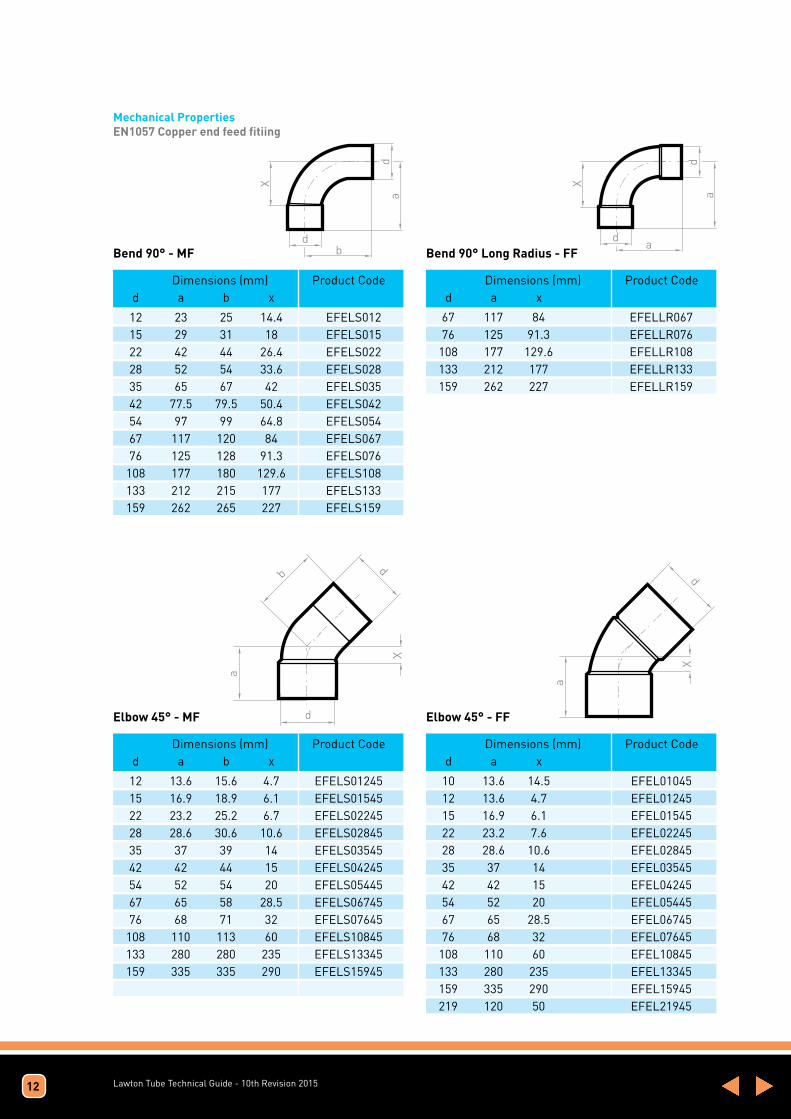
Mechanical PropertiesEN1057 Copper end feed fitiing
Dimensions (mm) Product Code d a b x
Dimensions (mm) Product Code d a b x
Dimensions (mm) Product Code d a x
Dimensions (mm) Product Code d a x
12 23 25 14.4 EFELS012 15 29 31 18 EFELS015 22 42 44 26.4 EFELS022 28 52 54 33.6 EFELS028 35 65 67 42 EFELS035 42 77.5 79.5 50.4 EFELS042 54 97 99 64.8 EFELS054 67 117 120 84 EFELS067 76 125 128 91.3 EFELS076 108 177 180 129.6 EFELS108 133 212 215 177 EFELS133 159 262 265 227 EFELS159
12 13.6 15.6 4.7 EFELS01245 15 16.9 18.9 6.1 EFELS01545 22 23.2 25.2 6.7 EFELS02245 28 28.6 30.6 10.6 EFELS02845 35 37 39 14 EFELS03545 42 42 44 15 EFELS04245 54 52 54 20 EFELS05445 67 65 58 28.5 EFELS06745 76 68 71 32 EFELS07645 108 110 113 60 EFELS10845 133 280 280 235 EFELS13345 159 335 335 290 EFELS15945
10 13.6 14.5 EFEL01045 12 13.6 4.7 EFEL01245 15 16.9 6.1 EFEL01545 22 23.2 7.6 EFEL02245 28 28.6 10.6 EFEL02845 35 37 14 EFEL03545 42 42 15 EFEL04245 54 52 20 EFEL05445 67 65 28.5 EFEL06745 76 68 32 EFEL07645 108 110 60 EFEL10845 133 280 235 EFEL13345 159 335 290 EFEL15945 219 120 50 EFEL21945
67 117 84 EFELLR067 76 125 91.3 EFELLR076 108 177 129.6 EFELLR108 133 212 177 EFELLR133 159 262 227 EFELLR159
Bend 90° - MF
Elbow 45° - MF Elbow 45° - FF
Bend 90° Long Radius - FF
12

Lawton Tube Technical Guide - 10th Revision 2015
Dimensions (mm) Product Code d a x
Dimensions (mm) Product Code d a x
Dimensions (mm) Product Code d a b x
8 16 6.8 EFEL008 10 16 7.4 EFEL010 12 16.2 7.6 EFEL012 15 29 18 EFEL015 22 28 12.6 EFEL022 28 35 16.6 EFEL028 35 46 23 EFEL035 42 55 28 EFEL042 54 70 38 EFEL054 67 83.5 50 EFEL067 76 91.5 58 EFEL076 108 127 79.5 EFEL108 133 127 79.5 EFEL133 159 160 100 EFEL159 219 200 130 EFEL219
8 12.8 6 EFTE008 10 15.4 7.6 EFTE010 12 18 9 EFTE012 15 20 9 EFTE015 22 28 12 EFTE022 28 34 15 EFTE028 35 42 20 EFTE035 42 50 23 EFTE042 54 61.5 29.5 EFTE054 67 78 42 EFTE067 76 80 46 EFTE076 108 112 64 EFTE108 133 135 85 EFTE133 159 160 100 EFTE159 219 178 115 EFTE219
12 16.2 18.5 7.6 EFELS012 15 19.2 21.5 8.5 EFELS015 22 28 30.5 12.6 EFELS022 28 35 37.5 16.6 EFELS028 35 46 54 24 EFELS035 42 56 66 29 EFELS042 54 71 82 39 EFELS054 67 83.5 95 50 EFELS067 76 91.5 105 58 EFELS076 108 127 137 79.5 EFELS108 133 127 137 79.5 EFELS133 159 160 180 100 EFELS159
Elbow 90° - FF Equal Tee - FFF
Street Elbow 90° - MF
13
Za
a
c
Dimensions (mm) Product Code Size a c Za
15mm x 1/2” 20 33 9 EFELMI0151/222mm x 3/4” 27 34 11 EFELMI0223/428mm x 1” 34 38 15 EFELMI0281
Suitable for: Copper x BSP parallel male thread
Male Elbow 90°

Lawton Tube Technical Guide - 10th Revision 201514
a
c
Zaa
c
Za
Dimensions (mm) Product Code Size a c Za
Dimensions (mm) Product Code Size a c Za
15mm x 1/2” 23 41 12 EFELWL0151/222mm x 3/4” 31 27 15 EFELWL0223/4
15mm x 1/2” 23 21 12 EFELFI0151/222mm x 3/4” 30 27 14 EFELFI0223/428mm x 1” 34 37 15 EFELFI 0281
Suitable for: Copper x BSP parallel female thread
Suitable for: Copper x BSP parallel female thread
Backplate Elbow 90°, 3 hole Female Elbow 90°
aa
c
ZaZa
Dimensions (mm) Product Code Size a c Za
Suitable for: Copper ends x BSP parallel female branch
15 x 15mm x 1/2” 23 21 12 EFTEFI015151/222 x 22mm x 3/4” 30 27 14 EFTEFI022223/428 x 28mm x 1” 37 26 19 EFTEFI028281
Female Met-Imp Tee
a
bd
x
c
ax
e
d
Dimensions (mm) Product Code d a b x
Dimensions (mm) Product Code d a b c e x
15 112.5 20 90 EFFC015 22 145 24 112 EFFC022
15 93 43 20 35 80 EFPC015 22 120 54 24 45 106 EFPC022
Full Crossover - FF Part Crossover - MF
Lawton Tube Technical Guide - 10th Revision 201515
aZ
Gd
b
d
a
Z
G
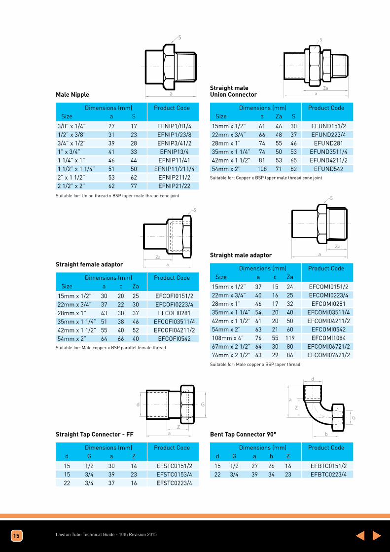
Dimensions (mm) Product Code d G a Z
Dimensions (mm) Product Code d G a b Z
15 1/2 30 14 EFSTC0151/2 15 3/4 39 23 EFSTC0153/4 22 3/4 37 16 EFSTC0223/4
15 1/2 27 26 16 EFBTC0151/2 22 3/4 39 34 23 EFBTC0223/4
Straight Tap Connector - FF Bent Tap Connector 90°
a
S
a
S
Za
Dimensions (mm) Product Code Size a S
Dimensions (mm) Product Code Size a Za S
3/8” x 1/4” 27 17 EFNIP1/81/41/2” x 3/8” 31 23 EFNIP1/23/83/4” x 1/2” 39 28 EFNIP3/41/21” x 3/4” 41 33 EFNIP13/41 1/4” x 1” 46 44 EFNIP11/411 1/2” x 1 1/4” 51 50 EFNIP11/211/42” x 1 1/2” 53 62 EFNIP211/22 1/2” x 2” 62 77 EFNIP21/22
15mm x 1/2” 61 46 30 EFUND151/222mm x 3/4” 66 48 37 EFUND223/428mm x 1” 74 55 46 EFUND28135mm x 1 1/4” 74 50 53 EFUND3511/442mm x 1 1/2” 81 53 65 EFUND4211/254mm x 2” 108 71 82 EFUND542
Male NippleStraight male Union Connector
Suitable for: Union thread x BSP taper male thread cone joint
Suitable for: Copper x BSP taper male thread cone joint
a
S
Zaa
S
Za
Dimensions (mm) Product Code Size a c Za
Dimensions (mm) Product Code Size a c Za
15mm x 1/2” 30 20 25 EFCOFI0151/222mm x 3/4” 37 22 30 EFCOFI0223/428mm x 1” 43 30 37 EFCOFI028135mm x 1 1/4” 51 38 46 EFCOFI03511/442mm x 1 1/2” 55 40 52 EFCOFI04211/254mm x 2” 64 66 40 EFCOFI0542
Suitable for: Male copper x BSP parallel female thread
Suitable for: Male copper x BSP taper thread
15mm x 1/2” 37 15 24 EFCOMI0151/222mm x 3/4” 40 16 25 EFCOMI0223/428mm x 1” 46 17 32 EFCOMI028135mm x 1 1/4” 54 20 40 EFCOMI03511/442mm x 1 1/2” 61 20 50 EFCOMI04211/254mm x 2” 63 21 60 EFCOMI0542108mm x 4” 76 55 119 EFCOMI108467mm x 2 1/2” 64 30 80 EFCOMI06721/276mm x 2 1/2” 63 29 86 EFCOMI07621/2
Straight female adaptorStraight male adaptor

Lawton Tube Technical Guide - 10th Revision 201516
Dimensions (mm) Product d1xd2xd3 a b c Xa Xb Xc Code
12x12x10 16 16 17.5 7 7 9.5 EFTE0121210 15x12x12 18 18 18 7 9 9 EFTE0151212 15x12x15 18 18 18 7 9 7 EFTE0151215 15x15x10 18 18 19 7 9 9 EFTE0151510 15x15x12 19 19 19 8 8 10 EFTE0151512 15x22x15 27 28 27 16 12 16 EFTE0152215 22x15x12 25 23 22.5 9 12 30.5 EFTE0221512 22x15x15 25 23 24 9 12 13 EFTE0221515 22x15x22 25 23 25 9 12 9 EFTE0221522 22x22x15 28 28 27 12 12 16 EFTE0222215 28x15x15 28 26 26.5 9 15 15.5 EFTE0281515 28x15x22 28 26 28.5 9 15 12.5 EFTE0281522 28x22x15 31 31 30 12 15 19 EFTE0282215 28x22x22 31 31 32 12 15 16 EFTE0282222 28x22x28 31 31 31 12 15 12 EFTE0282228 28x28x15 34 34 33 15 15 22 EFTE0282815 35x15x28 32.5 30 34 9.5 19 15 EFTE0351528 35x15x35 32.5 30 32.5 9.5 19 0.5 EFTE0351535 35x22x22 36 35 37.5 13 19 21.5 EFTE0352222 35x22x28 36 35 37 13 19 18 EFTE0352228 35x22x35 36 35 36 13 19 13 EFTE0352235 35x28x22 38 38 40 15 19 24 EFTE0352822 35x28x28 38 38 40 15 19 21 EFTE0352828 35x28x35 38 38 38 15 19 15 EFTE0352835 35x35x15 42 41 42 19 18 31 EFTE0353515 35x35x22 42 42 42.5 19 19 26.5 EFTE0353522 35x35x28 42 42 42.5 19 19 23.5 EFTE0353528 35x42x35 49.5 50 49.5 26.5 23 26.5 EFTE0354235 42x15x42 36.5 34 36.5 9.5 23 9.5 EFTE0421542 42x22x35 40.5 39 40.5 13.5 23 17 EFTE0422235 42x22x42 40 39 40 13 23 13 EFTE0422242 42x28x22 42.5 42 44 15.5 23 28 EFTE0422822 42x28x28 42.5 42 43 15.5 23 24 EFTE0422828 42x28x35 42.5 42 44 15.5 23 21 EFTE0422835 42x28x42 43 42 43 16 23 16 EFTE0422842
42x35x28 46 46 46 19 23 27 EFTE0423528 42x35x35 46 46 46.5 19 23 23.5 EFTE0423535 42x35x42 46.5 46 46.5 19.5 23 19.5 EFTE0423542 42x42x28 50 50 50 23 23 31 EFTE0424228 42x42x35 50 50 50 23 23 27 EFTE0424235 42x54x42 62 61 62 35 29 35 EFTE0425442 54x15x54 41.5 40 41.5 9.5 29 9.5 EFTE0541554 54x22x42 46 45 47 14 29 20 EFTE0542242 54x22x54 45 45 45 13 29 13 EFTE0542254 54x28x42 49 48 49.5 17 29 22.5 EFTE0542842 54x28x54 48 48 48 16 29 16 EFTE0542854 54x35x35 52 52 51 20 29 28 EFTE0543535 54x35x54 51.5 52 51.5 19.5 29 19.5 EFTE0543554 54x42x42 55 56 56.5 23 29 23 EFTE0544242 54x42x54 55 56 55 23 29 23 EFTE0544254 67x67x28 54.5 61 54.5 21 42 35 EFTE0676728 67x67x35 58.5 64 58.5 25 41 21 EFTE0676735 67x67x42 61 67 61 27 41 27 EFTE0676742 67x67x54 67 74 67 33.5 42 33.5 EFTE0676754 67x54x67 74 74 73 40 40 41 EFTE0675467 76x76x35 59 70 59.5 25.5 46 25.5 EFTE0767635 76x76x42 63 74 63 29 46 29 EFTE0767642 76x76x54 69 79 69 35 46 35 EFTE0767654 76x76x67 78 81 78 44.5 48 44.5 EFTE0767667108x108x22 72 88 72 24.5 72 24.5 EFTE10810822 108x108x35 77 92 22 29.5 65 29.5 EFTE10810835 108x108x42 80 97 80 32.5 70 32.5 EFTE10810842 108x108x54 86 97 86 38.5 65 38.5 EFTE10810845 108x108x67 91 97 91 43.5 64 43.5 EFTE10810867 108x108x76 95 97 95 47.5 64 47.5 EFTE10810876 133x133x108 139 142 139 89 94.5 89 EFTE133133108 159x159x76 101 120 101 53.5 86.5 53.5 EFTE15915976 159x159x133 130 120 130 92.5 86.5 82.5 EFTE159159133 159x159x108 117 142 117 69.5 94.5 69.5 EFTE159159108
Reducing Tee - FFF
Dimensions (mm) Product d1xd2xd3 a b c Xa Xb Xc Code

Lawton Tube Technical Guide - 10th Revision 201517
Dimensions (mm) Product Code d a x
Dimensions (mm) Product Code d a x
10x8 19 12 EFRED0108 12x8 21.5 14.5 EFRED0128 15x8 25 17 EFRED01508 15x8 38 30 EFREDLT01508 15x10 24 16 EFRED01510 15x12 40 30 EFREDLT01512 15x12 26 17.5 EFRED01512 22x12 33 25 EFRED02212 22x15 33 22 EFRED02215 28x12 41 32 EFRED02812 28x22 44 28 EFRED02822 35x15 50 39 EFRED03515 35x22 50 35 EFRED03522 35x28 50 32 EFRED03528 42x15 65 54 EFRED04215 42x18 59 46 EFRED04218 42x22 58 42 EFRED04222 42x28 58 40 EFRED04228 42x35 60 35 EFRED04235 54x15 70 60 EFRED05415 54x22 70 52 EFRED05422 54x28 70 45 EFRED05428 54x35 70 45 EFRED05435 54x42 70 45 EFRED05442 67x28 80 60 EFRED06728
67x35 80 60 EFRED06735 67x42 88 58 EFRED06742 67x54 80 48 EFRED06754 76x35 90 66 EFRED07635 76x42 90 60 EFRED07642 76x54 85 50 EFRED07654 76x64 80 50 EFRED07664 76x67 81 48.5 EFRED07667 108x35 116 84 EFRED10835 108x42 116 74 EFRED10842 108x54 116 84 EFRED10854 108x64 110 80 EFRED10864 108x67 112 80 EFRED10867 108x76 108 72 EFRED10876 133x76 119 82.5 EFRED13376 133x108 106 70 EFRED133108 159x76 150 110 EFRED15976 159x108 130 80 EFRED159108 159x133 123 70 EFRED159133219x159 150 90 EFRED219159
Reducer - MF
Dimensions (mm) Product Code d a x
Dimensions (mm) Product Code d a x
12x10 20 3 EFCP01210 15x12 24 4 EFCP01512 22x12 32 8 EFCP02212 22x15 32 8 EFCP02215 28x15 38 12 EFCP02815 28x22 40 6 EFCP02822 35x22 48 8 EFCP03522 35x28 48 6 EFCP03528 42x15 54 16 EFCP04215 42x22 56 13 EFCP04222 42x28 56 10 EFCP04228 42x35 60 10 EFCP04235 54x22 70 20 EFCP05422 54x28 70 20 EFCP05428 54x35 70 10 EFCP05435
54x42 70 10 EFCP05442 64x42 78 14 EFCP06442 64x54 78 12 EFCP06454 67x54 85 12 EFCP06754 76x54 84 18 EFCP07654 76x64 84 18 EFCP07664 76x67 85 18 EFCP07667 108x54 105 20 EFCP10854 108x76 105 20 EFCP10876 108x89 105 20 EFCP10889 133x76 110 35 EFCP13376 133x89 112 35 EFCP13389 133x108 100 25 EFCP133108 159x108 135 45 EFCP159108 159x133 120 50 EFCP159133
Reducing Coupling - FF

Lawton Tube Technical Guide - 10th Revision 201518
Dimensions (mm) Product Code d a x
Dimensions (mm) Product Code d a
8 15 1.2 EFCP008 10 18 1.5 EFCP010 12 19 1.8 EFCP012 15 24.5 1.8 EFCP015 22 33 2.2 EFCP022 28 40 3 EFCP028 35 49 3 EFCP035 42 38 4 EFCP042 54 69 5 EFCP054 67 72 5 EFCP067 76 72 5 EFCP076 108 100 3 EFCP108 133 100 3 EFCP133 159 100 4 EFCP159 219 116 5 EFCP219
8 6.8 EFEC008 10 7.8 EFEC010 12 8.6 EFEC012 15 10.6 EFEC015 22 15.4 EFEC022 28 18.4 EFEC028 35 23 EFEC035 42 27 EFEC042 54 32 EFEC054 67 33.5 EFEC067 76 33.5 EFEC076 108 47.5 EFEC108 159 62.5 EFEC159
Straight Coupling with Stop - FF Stop End - F
Dimensions (mm) Product Code d a
15 24 EFSC015 22 33 EFSC022 28 38 EFSC028 35 48 EFSC035 42 58 EFSC042 54 66 EFSC054
Slip Coupling - F
d
ax
Dimensions (mm) Product Code d a x
15 x 1/2 IMP 24.5 1.8 EFCP0151/222 x 3/4 IMP 33 2.2 EFCP0223/428 x 1 IMP 40 3 EFCP028135 x 1 1/4 IMP 49 3 EFCP03511/4
Met-Imp Coupling - FF

Lawton Tube Technical Guide - 10th Revision 2015
Lawton Soldering Flux Non-corrosive soft solder flux paste for soldering applications of copper to tin alloys. Water-soluble. With halogens. It complies with EN-ISO 9454 (2.1.2.C).
Packing Supplied in plastic jars of 113g or 453g boxed.
Chemical Composition 20% Etoxiled Fatty alcohol 5% Fatty acid 50% Amine chloride 25% Water
Hazards Identification Human: This product is not dangerous for the health Environment: It is not considered dangerous for the environment
First Aids Measures After inhalation: Bring the operative to breathe fresh air and consult a doctor. By contact with the skin: Wash with water and soap. By contact with eyes: Rinse out with abundant clear water during 15 minutes keeping open eyes and consult a opthamologist in case of persistent irritation. After ingestion: Wash out with abundant clear water during 15 minutes keeping open eyes and consult a opthamologist in case of persistent irritation.
Fire Fighting Measures Extinction means: use powders, foams or pulverised water. Peculiar danger by the exposure to the substance or its combustion: None; the product cannot explode and set on fire. Special protecting kit: Use a mask in closed locations
Accidental Release Measures Personal precautions: Described prevention measures at point 8 Cleaning method: Absorb the product with sand or sawdust. Clean the soiled surface with abundant hot water.
Handling And Storage Handling: Avoid always, if it is possible, the contact with the skin; therefore it’s recommended to use the applicator brush. Keep the bottle always tightly closed. Avoid the direct vapour’s inhalation caused by the heating Storage: None, in normal conditions of use
Exposure Control / Personal Protection. Exposure limit: None Breathing protection: Use facemask if you work large period of time in small and poorly ventilated spaces. In open spaces or in open air it is no necessary. Eye protection: It is recommended to use safety goggles in order to avoid splashing Skin protection: Only in the event of hyper-sensibility or allergy to the product, it is necessary to use gloves of neoprene. Normally the use of the application brush avoids skin irritations.
Physical And Chemical Properties Physical state at 20º C: Paste Freezing point: -10 º C Odour: None Ignition point: Not Determined (higher than 200ºC) Colour: Yellowish Vapour pressure: N.D. pH: 6/7 Density: 1.10 gr/cc Boiling point: 110 liquid part Water solubility: Total
Stability & Reactivity Stability: Stable emulsion up to 65º and activity till 300ºC Conditions to be avoided: None Materials to be avoided: None Hazardous decomposition products: None
Toxicological Information Severe Toxicity: DL50 oral rat. It is not toxic in its maximum dosage Poisoning routes: None Acute effects / symptoms: During the heating it may irritate slightly the eyes, the mucous nasal and the respiratory tract. Irritant to the skin if there are open wounds, making sting. There is not described any case of migraine, of spontaneous vomits or nausea produced by the local use of the product. Chronic effects: There is no described any case of chronic alteration produced by the local use of the product.
Ecological Information Ecological toxicity: None described
Waste Disposal Product Disposal: Respect local and national regulations. Dispose remaining product through an authorized waste disposal party. Used container disposal: Dispose container through an authorized waste disposal party.
Transport Information There is no special consideration necessary
Regulatory Information Classification: This product is not subject to classification as per the European Directive criteria regarding the control of dangerous substances and derivatives. The product has been adapted to the European Norm EN 29454 (2.1.2.C) of November 1993 about “Soft soldering fluxes” in substitution of the Norm DIN 8511
19

Lawton Tube Technical Guide - 10th Revision 2015
Leaded Solder Wire Lawtons leaded soft solder is a leaded alloy developed for plumbing and industrial applications of non-potable water supplies, heating and gas installations.
Type of Alloy Compliant to the European and international standard: EN-ISO 9453: 2006. Alloy No. 136 Alloy Designation Pb74Sn25Sb1 Melting Temperature 185 - 263oC
Packing Format: solid solder wire. Diameters: 0,35mm to 6mm. Delivered in reels of 500gr
Composition 25% Tin 74% Lead 1% Antimony Hazards Identification Eyes: Burns caused by the melted material Skin: Burns caused by the melted material Ingestion: Harmful due to lead content. Inhalation: It may be harmful and damage health in case of inhalation of the fumes emitted when this product is heated. It must be only used in ventilated areas. The activators of the resin do not implied any hazard given its low concentration in the final product.
First Aid Measures Eyes Flush immediately with water. Get dermatologist attention. Skin Wash with soap and water Ingestion Wash mouth with water and seek medical attention. Inhalation Evacuate to fresh air and seek medical attention
Fire Fighting Measures Specific hazards None, the product cannot explode or become inflamed. Extinguishing media Use pulverised water or foam Fire-fighting equipment Foresee breathing protection. Use face mask
Accidental Released Measures The supplied state of the material, present no risk of spillage. Individual precautions - Use gloves to avoid burns in case of contact with the product. Environmental protection precautions - Avoid the product entering into underground water pipes or ground waters. Cleaning methods - Collect the product by mechanical means, avoiding dust formation. To remove completely, clean the surface with plenty of water.
Handling and Storage Handling Whenever it is possible, avoid contact with skin. Use in well ventilated areas. Avoid direct inhalation of fumes. Preventive instructions against explosions and fires: no special requirements.
Storage - Requirements to be met by premises with storerooms and containers: No special requirements. Remarks for combined storage: not required Further instructions about storage conditions: Keep container tightly sealed. Store in tightly closed and dry environments. Storage class: VFD Class (Regulation on fluid fuels): deleted
Exposure Controls / Personal Protection Additional instructions for the fitting of technical facilities: With the molten material: use in ventilated environments, or well equipped with fume extraction. Components with acceptable limit values that require monitoring at the workplace: the product does not contain any relevant quantities of substances which limit values must be controlled in the workplace.
Additional instructions: the current lists at the time of preparation were used as basis.
Personal protective equipment. General protective and hygienic measures: Keep away from food, drinks and animal food. Wash hands before breaks and after work. Avoid contact with eyes and skin. Respiratory protection: Use mask in poorly ventilated places. Skin Protection: Gloves, only during the heating process. Eye protection: Wear safety goggles to prevent potential spills during the operational phase.
20

Lawton Tube Technical Guide - 10th Revision 2015
Exposure limit values:
Substance Name VLA-ED (mg/m3) VLA-EC (mg/m3)
Tin 2 - Lead 0.15 -
Physical and Chemical Properties Appearance Solid Colour Silver grey Odour None Flash point Not applicable Combustion properties Non oxidant Ignition Not applicable Danger of explosion Not applicable Relative density 10,54 Gr/cc.
Stability and Reactivity Stability Heat: heating may cause oxides steams and metal fumes. Humidity: Keep the product dry. Duration: Product not expired.
Toxicological Information Acute toxicity Tin: 40 μg/m3 Lead: 2,0 mg/ m3 Exposure ways Inhalation Acute effects / symptoms During its heating may cause slight eye , nasal mucous and respiratory tract irritation. Chronic effects Only after years of constant activity in unfavourable conditions, it may present risk of lung edema.
Ecological Information General notes: Level of damage to water 1 (self-classification): limited danger for water. Do not allow the undiluted product or in large quantities to infiltrate in ground waters, in water courses or in water pipes. It must not end up in sewages or drainage ditches.
Disposal Considerations Storage and handling Recommendation: Do not dispose of this substance with household waste. It should not reach sewer system. Unclean packaging Recommendation: Dispose of according to official regulations.
Information Concerning Transport There is no special consideration in this regard.
Regulatory Information Rating: This product is not subject to classification according to the criteria by the EC Directives on the Control of Dangerous Substances and Preparations.
R-Phrases: R 20/22 Harmful by inhalation and ingestion. S-Phrases: S 2 Keep out of the reach of children. S 13 Keep away from food, drinks and feed. S 21 Do not smoke while using it. S 26 In case of contact with eyes, rinse immediately with plenty water and consult a doctor.
WARNING: USE ONLY IN WELL VENTILATED AREAS as when this product is heated may emit dangerous fumes for health if inhaled.
21

Lawton Tube Technical Guide - 10th Revision 2015
Lead Free Solder Wire Lawtons lead free soft solder is a lead free alloy developed for plumbing and industrial applications of non-potable water supplies, heating and gas installations.
Type of Alloy Compliant to the European and international standard: EN-ISO 9453: 2006. Alloy No. 402 Alloy Designation S-Sn97Cu3 Melting Temperature 220 eutectic
Packing Format: solid solder wire. Diameters: 0,35mm to 6mm. Delivered in reels of 500gr
Composition 97% Tin 3% Copper Hazards Identification Eyes: Burns caused by the melted material Skin: Burns caused by the melted material Ingestion: Not applicable. Inhalation: Evacuate to fresh air and seek medical attention
First Aid Measures Eyes Flush immediately with water. Get dermatologist attention. Skin Wash with soap and water Ingestion Wash mouth with water and seek medical attention. Inhalation Evacuate to fresh air and seek medical attention
Fire Fighting Measures Specific hazards None, the product cannot explode or become inflamed. Extinguishing media Not applicable Fire-fighting equipment Not applicable
Accidental Released Measures The supplied state of the material, present no risk of spillage. Individual precautions - Use gloves to avoid burns in case of contact with the product. Environmental protection precautions - Avoid the product entering into underground water pipes or ground waters. Cleaning methods - Collect the product by mechanical means, avoiding dust formation. To remove completely, clean the surface with plenty of water.
Handling and Storage Handling Whenever it is possible, avoid contact with skin. Use in well ventilated areas. Avoid direct inhalation of fumes. Preventive instructions against explosions and fires: no special requirements.
Storage - Requirements to be met by premises with storerooms and containers: No special requirements. Remarks for combined storage: not required Further instructions about storage conditions:
Keep container tightly sealed. Store in tightly closed and dry environments.
Storage class: VFD Class (Regulation on fluid fuels): deleted
Exposure Controls / Personal Protection Additional instructions for the fitting of technical facilities: With the molten material: use in ventilated environments, or well equipped with fume extraction. Components with acceptable limit values that require monitoring at the workplace: the product does not contain any relevant quantities of substances which limit values must be controlled in the workplace.
Additional instructions: the current lists at the time of preparation were used as basis.
Personal protective equipment. General protective and hygienic measures: Keep away from food, drinks and animal food. Wash hands before breaks and after work. Avoid contact with eyes and skin. Respiratory protection: Use mask in poorly ventilated places. Skin Protection: Gloves, only during the heating process. Eye protection: Wear safety goggles to prevent potential spills during the operational phase.
22

Lawton Tube Technical Guide - 10th Revision 2015
Exposure limit values:
Substance Name VLA-ED (mg/m3) VLA-EC (mg/m3)
Tin 2 - Copper 1 -
Physical and Chemical Properties Appearance Solid Colour Silver grey Odour None Flash point Not applicable Combustion properties Non oxidant Ignition Not applicable Danger of explosion Not applicable Relative density 7.33
Stability and Reactivity Stability Heat: heating may cause oxides steams and metal fumes. Humidity: Keep the product dry. Duration: Product not expired.
Toxicological Information Acute toxicity Tin: 2 mg/ m3 Silver: 0,1 mg/ m3 Copper: 1 mg/ m3 Exposure ways Inhalation Acute effects / symptoms During its heating may cause slight eye , nasal mucous and respiratory tract irritation. Chronic effects Only after years of constant activity in unfavourable conditions, it may present risk of lung edema.
Ecological Information General notes: Level of damage to water 1 (self-classification): limited danger for water. Do not allow the undiluted product or in large quantities to infiltrate in ground waters, in water courses or in water pipes. It must not end up in sewers or drainage ditches.
Disposal Considerations Storage and handling Recommendation: Do not dispose of this substance with household waste. It should not reach sewer system. Unclean packaging Recommendation: Dispose of according to official regulations.
Information Concerning Transport There is no special consideration in this regard.
Regulatory Information Rating: This product is not subject to classification according to the criteria by the EC Directives on the Control of Dangerous Substances and Preparations.
R-Phrases: R 20/22 Harmful by inhalation and ingestion. S-Phrases: S 2 Keep out of the reach of children. S 13 Keep away from food, drinks and feed. S 21 Do not smoke while using it. S 26 In case of contact with eyes, rinse immediately with plenty water and consult a doctor.
WARNING: USE ONLY IN WELL VENTILATED AREAS as when this product is heated may emit dangerous fumes for health if inhaled.
23

Lawton Tube Technical Guide - 10th Revision 2015
Medical Gas Tubes BS EN 13348
Specifically designed for copper medical gas and vacuum systems. Superseding earlier ‘hybridised’ copper tube standards such BS EN 1057 & BS 2871 Part 1 Table X Conforms to HTM 02-01:2006 & NHS engineering spec. C11
Specific Benefits Include: · Tighter limits on cleanliness determination. · Improved identification to avoid confusion with similar sizes of water service tube. · Lawton Tubes are the first British company to be awarded the kitemark licence to supply to this standard.
Material Analysis Material Grade Phosphorus de-oxidised copper; Cu-DHP or CW024A as defined in BS EN 1976. Minimum Copper Content 99.90 % (including silver) Phosphorus 0.015-0.040 % Total Impurity Maxima 0.060 % (excluding phosphorus and silver) The melting point of copper is 1083ºC and it has a density of 8.9 gm/cc
Cleanliness Maximum total carbon content 0.20 mg/dm2.
Packaging Each tube individually end capped, tube bundles polythene wrapped* and sealed.
Marking Sizes 12 -108mm copper tubes are stamped with: · Tube size · Kitemark · EN 13348 · Temper · Manufacturer · Date & Batch Code 12mm to 28mm sizes are also inkjet marked with additional data to enable traceability
Sizes above 108mm (133mm/159mm/219mm) are made to EN 1057 and cleaned to EN 13348
24
No KM66240

Lawton Tube Technical Guide - 10th Revision 201525
Temper
Half Hard Half Hard Half Hard Half Hard Half Hard Half Hard Half Hard Half Hard
Hard Half Hard
Hard Hard
Half Hard Hard Hard
Half Hard Hard Hard Hard Hard Hard Hard Hard Hard Hard Hard
Wall (mm)
0.6 (TX) 0.8 (TY) 0.7 (TX) 1.0 (TY) 0.9 (TX) 1.2 (TY) 0.9 (TX) 1.2 (TY)
1.0 1.2 (TX) 1.5 (TY)
1.0 1.2 (TX) 1.5 (TY)
1.0 1.2 (TX) 2.0 (TY) 1.2 (TX) 2.0 (TY) 1.5 (TX) 2.0 (TY) 1.5 (TX) 2.5 (TY) 1.5 (TX) 2.0 (TX) 3.0 (TX)
O.D. (mm)
12 12 15 15 22 22 28 28 35 35 35 42 42 42 54 54 54
66.7 66.7 76.1 76.1 108 108 133 159 219
Diameter Tolerance Mean Including Ovality
± 0.04mm ±0.09mm ± 0.04mm ±0.09mm ± 0.04mm ±0.09mm ± 0.04mm ±0.09mm ± 0.05mm ±0.10mm ± 0.05mm ±0.10mm ± 0.05mm ±0.10mm ± 0.05mm ±0.10mm ± 0.06mm ±0.07mm ± 0.06mm ±0.11mm ± 0.06mm ±0.07mm ± 0.06mm ±0.07mm ± 0.06mm ±0.11mm ± 0.06mm ±0.07mm ± 0.06mm ±0.07mm ± 0.06mm ±0.11mm ± 0.06mm ±0.07mm ± 0.07mm ±0.10mm ± 0.07mm ±0.10mm ± 0.07mm ±0.10mm ± 0.07mm ±0.10mm ± 0.07mm ±0.20mm ± 0.07mm ±0.20mm ± 0.20mm ±0.70mm ± 0.20mm ±0.70mm ± 0.60mm ±1.50mm
Thickness Tolerance
±10% ±10% ±10% ±13% ±10% ±15% ±10% ±15% ±15% ±10% ±10% ±15% ±10% ±10% ±15% ±10% ±10% ±15% ±15% ±15% ±15% ±15% ±15% ±15% ±15% ±15%
Max Working Pressure bar up to 65oC
63 87 58 87 51 69 40 55 42 42 64 35 35 53 27 27 55 26 45 29 39 20 34 16 18 20
Dimensions and Tolerances
Working pressures are to BS 2871:part1:1971
Mechanical Properties
Material Temper EN 1173
R250 (Half Hard) R290 (Hard)
Hardness (Indicative) HV5 VPN
75-100 Over 100
Elongation min.(%)
30 (TX) 20 (TY) 3
Tensile Strength min. (N/mm2)
250 290
Medical Gas Tubes to BS EN 13348

Lawton Tube Technical Guide - 10th Revision 2015
Medical Gas Metric Endfeed Fittings Degreased copper end feed type fittings manufactured to: BS EN 1254-1:1998 Part 1 Specification for copper and copper alloy fittings with capillary ends for soldering and brazing for use with copper tubes. BS EN 1254-1:1998 Part 5 Specification for copper and copper alloy fittings with short ends for capillary brazing for use with copper tubes. All fittings are supplied in individually sealed protective polythene bags and are specifically designed for copper medical gas and vacuum systems.
Specific Benefits Include: Complies to NHS (UK) Health Technical Memorandum 02-01:2006 All fittings supplied contain less than 100mg/m2 (0.01mg/cm2) of hydrocarbons on the degreased surface. Improved identification to avoid confusion with similar sizes of water service fittings. All individually sealed protective polythene bags are product labelled. Fittings are supplied in reinforced cardboard boxes, labelled with product information and outline drawing of fitting. Each fitting is engraved with unique branding, where space permits.
Service Temperature*
Max 1100C
16 bar 10 bar 10 bar
650C
25 bar 16 bar 16 bar
300C
25 bar 25 bar 16 bar
Size
8mm to 28mm 35mm to 54mm 67mm
Min -400C
25 bar 25 bar 16 bar
Working Temperatures and Pressure
*LTC Fittings performance when correctly assembled with Lawton Tube’s EN13448 copper tube using tin/copper soft solder EN 29453 ortin/silver soft solder EN 29453
Service Temperature**
Size
8mm 10mm 12mm 15mm 22mm 28mm 35mm 42mm 54mm
650C
62.5 bar 50.9 bar 42.9 bar 40.3 bar 35.6 bar 28.2 bar 25.2 bar 23.2 bar 19.8 bar
Min -1960C
62.5 bar 50.9 bar 42.9 bar 40.3 bar 35.6 bar 28.2 bar 25.2 bar 23.2 bar 19.8 bar
1200C
58.8 bar 47.9 bar 40.3 bar 37.9 bar 33.5 bar 26.5 bar 23.7 bar 21.8 bar 18.6 bar
1500C
46.7 bar 38.0 bar 32.0 bar 30.1 bar 26.6 bar 21.1 bar 18.8 bar 17.3 bar 14.7 bar
1750C
35.5 bar 28.9 bar 24.3 bar 22.8 bar 20.2 bar 16.0 bar 14.3 bar 13.1 bar 11.2 bar
Max 2000C
23.3 bar 19.0 bar 16.0 bar 15.0 bar 13.3 bar 10.5 bar 9.4 bar 8.6 bar 7.4 bar
** Max hydraulic working pressure for LTC fittings when assembled with Lawton Tube’s EN13348 copper tube using hard solder (brazing alloy) to EN 1044
Service Temperature***
Size
67mm 76mm 108mm 133mm 159mm
650C
18.6 bar 18.6 bar 17.2 bar 10.5 bar 11.7 bar
Min -1960C
18.6 bar 18.6 bar 17.2 bar 10.5 bar 11.7 bar
1200C
17.5 bar 17.5 bar 16.2 bar 8.5 bar 9.7 bar
1500C
14.0 bar 14.0 bar 12.9 bar 7.7 bar 8.6 bar
Max 2000C
6.9 bar 6.9 bar 6.4 bar 4.1 bar 4.6 bar
*** Max hydraulic working pressure for LTC fittings when assembled with Lawton Tube’s EN13348 copper tube using hard solder (brazing alloy) to EN 1044
26
No KM53646654mm sample

Lawton Tube Technical Guide - 10th Revision 2015
Mechanical Properties EN3448 Copper end feed fitiing
Bend 90° - MF
Elbow 45° - MF Elbow 45° - FF
Bend 90° - FF
27
Dimensions (mm) Product Code d a b x
Dimensions (mm) Product Code d a b x
Dimensions (mm) Product Code d a x
Dimensions (mm) Product Code d a x
12 23 25 14.4 MEDELS012 15 29 31 18 MEDELS015 22 42 44 26.4 MEDELS022 28 52 54 33.6 MEDELS028 35 65 67 42 MEDELS035 42 77.5 79.5 50.4 MEDELS042 54 97 99 64.8 MEDELS054 67 117 120 84 MEDELS067 76 125 128 91.3 MEDELS076 108 177 180 129.6 MEDELS108 133 212 215 177 MEDELS133 159 262 265 227 MEDELS159
12 13.6 15.6 4.7 MEDELS01245 15 16.9 18.9 6.1 MEDELS01545 22 23.2 25.2 6.7 MEDELS02245 28 28.6 30.6 10.6 MEDELS02845 35 37 39 14 MEDELS03545 42 42 44 15 MEDELS04245 54 52 54 20 MEDELS05445 67 65 58 28.5 MEDELS06745 76 68 71 32 MEDELS07645 108 110 113 60 MEDELS10845 133 280 280 235 MEDELS13345 159 335 335 290 MEDELS05945
12 13.6 4.7 MEDEL01245 15 16.9 6.1 MEDEL01545 22 23.2 7.6 MEDEL02245 28 28.6 10.6 MEDEL02845 35 37 14 MEDEL03545 42 42 15 MEDEL04245 54 52 20 MEDEL05445 67 65 28.5 MEDEL06745 76 68 32 MEDEL07645 108 110 60 MEDEL10845 133 280 235 MEDEL13345 159 335 290 MEDEL15945 219 120 50 MEDEL21945
12 23 14.4 MEDEL012 15 29 18 MEDEL015 22 42 26.4 MEDEL022 28 52 33.6 MEDEL028 35 65 42 MEDEL035 42 77.5 50.4 MEDEL042 54 97 64.8 MEDEL054 67 117 84 MEDEL067 76 125 91.3 MEDEL076 108 177 129.6 MEDEL108 133 212 177 MEDEL133 159 262 227 MEDEL159
Lawton Tube Technical Guide - 10th Revision 2015
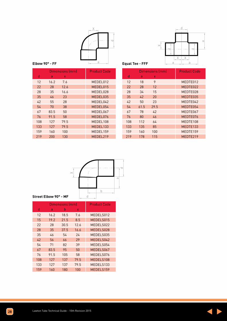
Elbow 90° - FF Equal Tee - FFF
Street Elbow 90° - MF
28
Dimensions (mm) Product Code d a x
Dimensions (mm) Product Code d a x
Dimensions (mm) Product Code d a b x
12 16.2 7.6 MEDEL012 22 28 12.6 MEDEL015 28 35 16.6 MEDEL028 35 46 23 MEDEL035 42 55 28 MEDEL042 54 70 38 MEDEL054 67 83.5 50 MEDEL067 76 91.5 58 MEDEL076 108 127 79.5 MEDEL108 133 127 79.5 MEDEL133 159 160 100 MEDEL159 219 200 130 MEDEL219
12 18 9 MEDTE012 22 28 12 MEDTE022 28 34 15 MEDTE028 35 42 20 MEDTE035 42 50 23 MEDTE042 54 61.5 29.5 MEDTE054 67 78 42 MEDTE067 76 80 46 MEDTE076 108 112 64 MEDTE108 133 135 85 MEDTE133 159 160 100 MEDTE159 219 178 115 MEDTE219
12 16.2 18.5 7.6 MEDELS012 15 19.2 21.5 8.5 MEDELS015 22 28 30.5 12.6 MEDELS022 28 35 37.5 16.6 MEDELS028 35 46 54 24 MEDELS035 42 56 66 29 MEDELS042 54 71 82 39 MEDELS054 67 83.5 95 50 MEDELS067 76 91.5 105 58 MEDELS076 108 127 137 79.5 MEDELS108 133 127 137 79.5 MEDELS133 159 160 180 100 MEDELS159

Lawton Tube Technical Guide - 10th Revision 2015
Reducing Tee - FFF
Dimensions (mm) Product d1xd2xd3 a b c Xa Xb Xc Code
12x12x10 16 16 17.5 7 7 9.5 MEDTE0121210 15x12x12 18 18 18 7 9 9 MEDTE0151212 15x12x15 18 18 18 7 9 7 MEDTE0151215 15x15x12 19 19 19 8 8 10 MEDTE0151512 15x22x15 27 28 27 16 12 16 MEDTE0152215 22x15x12 25 23 22.5 9 12 30.5 MEDTE0221512 22x15x15 25 23 24 9 12 13 MEDTE0221515 22x15x22 25 23 25 9 12 9 MEDTE0221522 22x22x15 28 28 27 12 12 16 MEDTE0222215 28x15x15 28 26 26.5 9 15 15.5 MEDTE0281515 28x15x22 28 26 28.5 9 15 12.5 MEDTE0281522 28x22x15 31 31 30 12 15 19 MEDTE0282215 28x22x22 31 31 32 12 15 16 MEDTE0282222 28x22x28 31 31 31 12 15 12 MEDTE0282228 28x28x15 34 34 33 15 15 22 MEDTE0282815 35x15x28 32.5 30 34 9.5 19 15 MEDTE0351528 35x15x35 32.5 30 32.5 9.5 19 0.5 MEDTE0351535 35x22x22 36 35 37.5 13 19 21.5 MEDTE0352222 35x22x28 36 35 37 13 19 18 MEDTE0352228 35x22x35 36 35 36 13 19 13 MEDTE0352235 35x28x22 38 38 40 15 19 24 MEDTE0352822 35x28x28 38 38 40 15 19 21 MEDTE0352828 35x28x35 38 38 38 15 19 15 MEDTE0352835 35x35x15 42 41 42 19 18 31 MEDTE0353515 35x35x22 42 42 42.5 19 19 26.5 MEDTE0353522 35x35x28 42 42 42.5 19 19 23.5 MEDTE0353528 35x42x35 49.5 50 49.5 26.5 23 26.5 MEDTE0354235 42x15x42 36.5 34 36.5 9.5 23 9.5 MEDTE0421542 42x22x35 40.5 39 40.5 13.5 23 17 MEDTE0422235 42x22x42 40 39 40 13 23 13 MEDTE0422242 42x28x22 42.5 42 44 15.5 23 28 MEDTE0422822 42x28x28 42.5 42 43 15.5 23 24 MEDTE0422828 42x28x35 42.5 42 44 15.5 23 21 MEDTE0422835 42x28x42 43 42 43 16 23 16 MEDTE0422842
42x35x28 46 46 46 19 23 27 MEDTE0423528 42x35x35 46 46 46.5 19 23 23.5 MEDTE0423535 42x35x42 46.5 46 46.5 19.5 23 19.5 MEDTE0423542 42x42x28 50 50 50 23 23 31 MEDTE0424228 42x42x35 50 50 50 23 23 27 MEDTE0424235 42x54x42 62 61 62 35 29 35 MEDTE0425442 54x15x54 41.5 40 41.5 9.5 29 9.5 MEDTE0541554 54x22x42 46 45 47 14 29 20 MEDTE0542242 54x22x54 45 45 45 13 29 13 MEDTE0542254 54x28x42 49 48 49.5 17 29 22.5 MEDTE0542842 54x28x54 48 48 48 16 29 16 MEDTE0542854 54x35x35 52 52 51 20 29 28 MEDTE0543535 54x35x54 51.5 52 51.5 19.5 29 19.5 MEDTE0543554 54x42x42 55 56 56.5 23 29 23 MEDTE0544242 54x42x54 55 56 55 23 29 23 MEDTE0544254 67x67x28 54.5 61 54.5 21 42 35 MEDTE0676728 67x67x35 58.5 64 58.5 25 41 21 MEDTE0676735 67x67x42 61 67 61 27 41 27 MEDTE0676742 67x67x54 67 74 67 33.5 42 33.5 MEDTE0676754 67x5467 74 74 73 40 40 41 MEDTE0675467 76x76x35 59 70 59.5 25.5 46 25.5 MEDTE0767635 76x76x42 63 74 63 29 46 29 MEDTE0767642 76x76x54 69 79 69 35 46 35 MEDTE0767654 76x76x67 78 81 78 44.5 48 44.5 MEDTE0767667 108x108x22 72 88 72 24.5 72 24.5 MEDTE10810822 108x108x35 77 92 22 29.5 65 29.5 MEDTE10810835 108x108x42 80 97 80 32.5 70 32.5 MEDTE10810842 108x108x54 86 97 86 38.5 65 38.5 MEDTE10810854 108x108x67 91 97 91 43.5 64 43.5 MEDTE10810867 108x108x76 95 97 95 47.5 64 47.5 MEDTE10810876 133x133x108 139 142 139 89 94.5 89 MEDTE133133108 159x159x76 101 120 101 53.5 86.5 53.5 MEDTE15915976 159x159x133 130 120 130 92.5 86.5 82.5 MEDTE159159133 159x159x108 117 142 117 69.5 94.5 69.5 MEDTE159159108
Dimensions (mm) Product d1xd2xd3 a b c Xa Xb Xc Code
29

Lawton Tube Technical Guide - 10th Revision 2015
Reducer - MF
Reducing Coupling - FF
30
Dimensions (mm) Product Code d a x
Dimensions (mm) Product Code d a x
12x8 21.5 14.5 MEDRED0128 15x12 26 17.5 MEDRED01512 22x12 33 25 MEDRED02212 22x15 33 22 MEDRED02215 28x12 41 32 MEDRED02812 28x22 44 28 MEDRED02822 35x15 50 39 MEDRED03515 35x22 50 35 MEDRED03522 35x28 50 32 MEDRED03528 42x15 65 54 MEDRED04215 42x18 59 46 MEDRED04218 42x22 58 42 MEDRED04222 42x28 58 40 MEDRED04228 42x35 60 35 MEDRED04235 54x15 70 60 MEDRED05415 54x22 70 52 MEDRED05422 54x28 70 45 MEDRED05428 54x35 70 45 MEDRED05435 54x42 70 45 MEDRED05442 67x28 80 60 MEDRED06728
67x35 80 60 MEDRED06735 67x42 88 58 MEDRED06742 67x54 80 48 MEDRED06754 76x35 90 66 MEDRED07635 76x42 90 60 MEDRED07642 76x54 85 50 MEDRED07654 76x64 80 50 MEDRED07664 76x67 81 48.5 MEDRED07667 108x35 116 84 MEDRED10835 108x42 116 74 MEDRED10842 108x54 116 84 MEDRED10854 108x64 110 80 MEDRED10864 108x67 112 80 MEDRED10867 108x76 108 72 MEDRED10876 133x76 119 82.5 MEDRED13376 133x108 106 70 MEDRED133108 159x76 150 110 MEDRED15976 159x108 130 80 MEDRED159108 159x133 123 70 MEDRED159133219x159 150 90 MEDRED219159
Dimensions (mm) Product Code d a x
Dimensions (mm) Product Code d a x
12x10 20 3 MEDCP01210 15x12 24 4 MEDCP01512 22x12 32 8 MEDCP02212 22x15 32 8 MEDCP02215 28x15 38 12 MEDCP02815 28x22 40 6 MEDCP02822 35x22 48 8 MEDCP03522 35x28 48 6 MEDCP03528 42x15 54 16 MEDCP04215 42x22 56 13 MEDCP04222 42x28 56 10 MEDCP04228 42x35 60 10 MEDCP04235 54x22 70 20 MEDCP05422 54x28 70 20 MEDCP05428 54x35 70 10 MEDCP05435
54x42 70 10 MEDCP05442 64x42 78 14 MEDCP06442 64x54 78 12 MEDCP06454 67x54 85 12 MEDCP06754 76x54 84 18 MEDCP07654 76x64 84 18 MEDCP07664 76x67 85 18 MEDCP07667 108x54 105 20 MEDCP10854 108x76 105 20 MEDCP10876 108x89 105 20 MEDCP10889 133x76 110 35 MEDCP13376 133x89 112 35 MEDCP13389 133x108 100 25 MEDCP133108 159x108 135 45 MEDCP159108 159x133 120 50 MEDCP159133

Lawton Tube Technical Guide - 10th Revision 2015
Straight Coupling with Stop - FF Stop End - F
Slip Coupling - F
31
Dimensions (mm) Product Code d a x
Dimensions (mm) Product Code d a
12 19 1.8 MEDCP012 15 24.5 1.8 MEDCP015 22 33 2.2 MEDCP022 28 40 3 MEDCP028 35 49 3 MEDCP035 42 38 4 MEDCP042 54 69 5 MEDCP054 67 72 5 MEDCP067 76 72 5 MEDCP076 108 100 3 MEDCP108 133 100 3 MEDCP133 159 100 4 MEDCP159 219 116 5 MEDCP219
12 8.6 MEDEC012 15 10.6 MEDEC015 22 15.4 MEDEC022 28 18.4 MEDEC028 35 23 MEDEC035 42 27 MEDEC042 54 32 MEDEC054 67 33.5 MEDEC067 76 33.5 MEDEC076 108 47.5 MEDEC108 159 62.5 MEDEC159
Dimensions (mm) Product Code d a
15 24 MEDSC015 22 33 MEDSC022 28 38 MEDSC028 35 48 MEDSC035 42 58 MEDSC042 54 66 MEDSC054

Lawton Tube Technical Guide - 10th Revision 2015
Brazing RodsAll Lawton solder rods conform to HTM 02 Spec
Type of Product
5% Silver Brazing Alloy
Composition
5% Silver
89% Copper
6% Phosphorous
Impurities to BSEN 17672 Group CP
Alloy conforms to: BSEN 17672:2010 CuP104
Melting Range
645 - 815oC
Appearance
Copper coloured metal
Occupational Health Data
TLV
Odour threshold
Silver 0.1mg/m3 as fume Phosphorous 1mg/m3 as phosphoric acid Copper 0.2mg/m3 as fume
Working Temp
710oC
Tensile Strength 600 N/mm2
Hardness (HV) 190
Elongation 7%
Electrical Conductivity 10% I.A.C.S. at 20oC
32

Lawton Tube Technical Guide - 10th Revision 2015
Refrigeration and Air Conditioning Tubes Pipeline solutions for refrigeration and air conditioning, all to EN 12735-1.
Our copper tubing is designed specifically for refrigeration and air conditioning use and accordingly cleaned, nitrogen-purged and capped.
Material Analysis Material Grade Phosphorus de-oxidised copper; Cu-DHP or CW024A as defined in BS EN 1976. Minimum Copper Content 99.90 % (including silver) Phosphorus 0.015-0.040 % Total Impurity Maxima 0.060 % (excluding phosphorus and silver) The melting point of copper is 1083ºC and it has a density of 8.9 gm/cc
Mechanical Properties
Material Temper EN 1173
R220 (soft) R250 (Half Hard)
R290 (Hard)
Hardness (Indicative) HV5 VPN
40-70 75-100
Over 100
Elongation min.(%) 40 30 3
Tensile Strength min. (N/mm2)
220 250 290
BS EN 12735-1 Refrigeration and Air Conditioning Tubes
The table below and on the next page give the maximum working pressure (MWP) They have been calculated based on the requirements of EN378 using the stress values according to BS 1306. Although straight tube is supplied in either half hard or fully hard condition, we have also quoted figures based on annealed condition which is representative of the tube in the area immediately surrounding brazed joints. The maximum test pressure can be 1.5 times that of the (MWP)
Standard Copper Coiled Tube to EN 12735-1 R220
Economy Copper Coiled Tube to EN 12735-1 R220
O.D. (inches)
1/4 5/16 5/16 3/8 1/2 5/8 3/4 7/8
O.D. (inches)
1/4 5/16 3/8 1/2 5/8 3/4 7/8
1 1/8
Wall (inches)
0.028 0.028 0.036 0.032 0.032 0.036 0.040 0.040
Wall (inches)
0.020 0.020 0.020 0.022 0.028 0.032 0.040 0.048
Gauge (SWG)
22 22 20 21 21 20 19 19
Gauge (SWG)
25 25 25 24 22 21 19 18
92 72 94 68 50 45 39 33
72 51 47 37 34 33 33 33
Max Working Pressure in annealed condition
Max Working Pressure in annealed condition
33
Lawton Tube Technical Guide - 10th Revision 201534
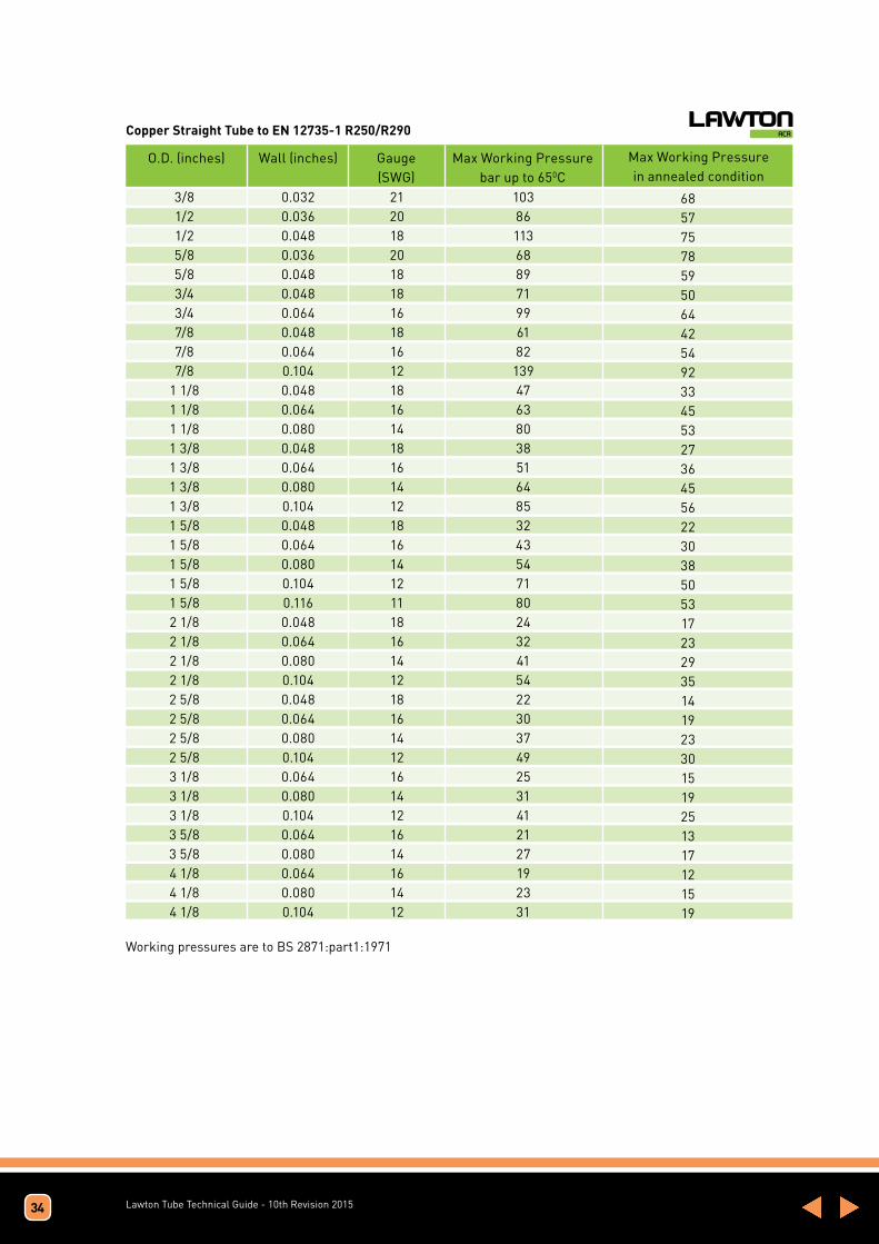
Copper Straight Tube to EN 12735-1 R250/R290
O.D. (inches) Gauge (SWG)
Max Working Pressure bar up to 650C
68 57 75 78 59 50 64 42 54 92 33 45 53 27 36 45 56 22 30 38 50 53 17 23 29 35 14 19 23 30 15 19 25 13 17 12 15 19
Max Working Pressure in annealed condition
Wall (inches)
103 86 113 68 89 71 99 61 82 139 47 63 80 38 51 64 85 32 43 54 71 80 24 32 41 54 22 30 37 49 25 31 41 21 27 19 23 31
21 20 18 20 18 18 16 18 16 12 18 16 14 18 16 14 12 18 16 14 12 11 18 16 14 12 18 16 14 12 16 14 12 16 14 16 14 12
0.032 0.036 0.048 0.036 0.048 0.048 0.064 0.048 0.064 0.104 0.048 0.064 0.080 0.048 0.064 0.080 0.104 0.048 0.064 0.080 0.104 0.116 0.048 0.064 0.080 0.104 0.048 0.064 0.080 0.104 0.064 0.080 0.104 0.064 0.080 0.064 0.080 0.104
3/8 1/2 1/2 5/8 5/8 3/4 3/4 7/8 7/8 7/8
1 1/8 1 1/8 1 1/8 1 3/8 1 3/8 1 3/8 1 3/8 1 5/8 1 5/8 1 5/8 1 5/8 1 5/8 2 1/8 2 1/8 2 1/8 2 1/8 2 5/8 2 5/8 2 5/8 2 5/8 3 1/8 3 1/8 3 1/8 3 5/8 3 5/8 4 1/8 4 1/8 4 1/8
Working pressures are to BS 2871:part1:1971

Lawton Tube Technical Guide - 10th Revision 2015
ACR Fitting Range Copper end feed type fittings manufactured to:
ASME B16.22-2013-Wrought Copper and Copper Alloy Solder Joint pressure Fittings.
Specific benefits include:
All sealed in protective polythene bags and are product labelled. Fittings are supplied in reinforced cardboard boxes, labelled with product information and outline drawing of fitting.Each fitting is engraved with unique branding, space permitting
3 1/8 sample
35
Fittings for Co2
Degreased copper fittings specifically for ACR and
manufactured to ASME B16.22-2001 which can be used in
assemblies subject to the Pressure Equipment Directive.
The burst pressure of each fitting size at 55ºc has been
determined and a safety factor of at least 3 has been applied
to establish a recommended maximum working pressure.
All testing has been conducted in accordance with BS EN
378-2:2008 (+A1:2009).
Maximum Working Pressures
Size Burst Pressure Maximum Working Pressure at 55ºC
1/4 “ 500 bar 150 bar 3/8 ” 360 bar 120 bar 1/2 “ 320 bar 100 bar 5/8 “ 300 bar 100 bar 3/4 “ 280 bar 90 bar 7/8 “ 240 bar 80 bar 1 1/8 “ 220 bar 75 bar 1 3/8 “ 220 bar 65 bar 1 5/8 “ 180 bar 55 bar
Pressure Equipment DirectiveDeclaration of Conformity
We hereby certify that the fittings stipulated above, which may be used in assemblies
subject to the Pressure Equipment Directive, complies with all relevant provisions, National
Laws and Regulations adopting this Directive.
Product DescriptionA range of ACR fittings up to 7/8” nominal diameter are suitable when used with CO
2
applications not exceeding 80 bar, or 550c, conforming to EN 378-2.
Supplier: The Lawton Tube Company, Torrington Avenue, Coventry, CV4 9AB
Standard: BS EN 378-2:2008 (+A1:2009)Notified Body: Not applicable
_____________________Oliver Lawton, Managing Director
Date:
13th April 2011Fittings manufactured under Sound Engineering Practice cannot be CE marked,
under the terms and conditions of the Directive.
Lawton Tube Technical Guide - 10th Revision 2015
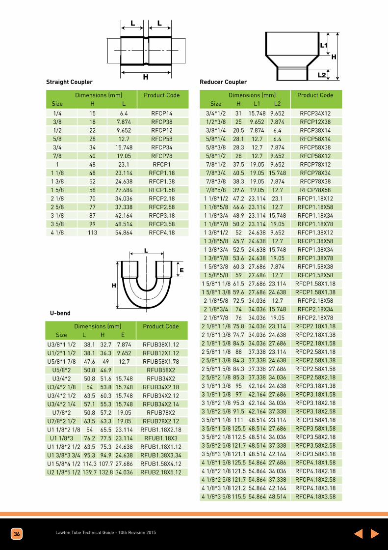
Straight Coupler Reducer Coupler
L L
H
L1
L2
H
Dimensions (mm) Product Code Size H L
Dimensions (mm) Product Code Size H L1 L2
1/4 15 6.4 RFCP14 3/8 18 7.874 RFCP38 1/2 22 9.652 RFCP12 5/8 28 12.7 RFCP58 3/4 34 15.748 RFCP34 7/8 40 19.05 RFCP78 1 48 23.1 RFCP1 1 1/8 48 23.114 RFCP1.18 1 3/8 52 24.638 RFCP1.38 1 5/8 58 27.686 RFCP1.58 2 1/8 70 34.036 RFCP2.18 2 5/8 77 37.338 RFCP2.58 3 1/8 87 42.164 RFCP3.18 3 5/8 99 48.514 RFCP3.58 4 1/8 113 54.864 RFCP4.18
3/4*1/2 31 15.748 9.652 RFCP34X12 1/2*3/8 25 9.652 7.874 RFCP12X38 3/8*1/4 20.5 7.874 6.4 RFCP38X14 5/8*1/4 28.1 12.7 6.4 RFCP58X14 5/8*3/8 28.3 12.7 7.874 RFCP58X38 5/8*1/2 28 12.7 9.652 RFCP58X12 7/8*1/2 37.5 19.05 9.652 RFCP78X12 7/8*3/4 40.5 19.05 15.748 RFCP78X34 7/8*3/8 38.3 19.05 7.874 RFCP78X38 7/8*5/8 39.6 19.05 12.7 RFCP78X58 1 1/8*1/2 47.2 23.114 23.1 RFCP1.18X12 1 1/8*5/8 46.6 23.114 12.7 RFCP1.18X58 1 1/8*3/4 48.9 23.114 15.748 RFCP1.18X34 1 1/8*7/8 50.2 23.114 19.05 RFCP1.18X78 1 3/8*1/2 52 24.638 9.652 RFCP1.38X12 1 3/8*5/8 45.7 24.638 12.7 RFCP1.38X58 1 3/8*3/4 52.5 24.638 15.748 RFCP1.38X34 1 3/8*7/8 53.6 24.638 19.05 RFCP1.38X78 1 5/8*3/8 60.3 27.686 7.874 RFCP1.58X38 1 5/8*5/8 59 27.686 12.7 RFCP1.58X58 1 5/8*1 1/8 61.5 27.686 23.114 RFCP1.58X1.18 1 5/8*1 3/8 59.6 27.686 24.638 RFCP1.58X1.38 2 1/8*5/8 72.5 34.036 12.7 RFCP2.18X58 2 1/8*3/4 74 34.036 15.748 RFCP2.18X34 2 1/8*7/8 76 34.036 19.05 RFCP2.18X78 2 1/8*1 1/8 75.8 34.036 23.114 RFCP2.18X1.18 2 1/8*1 3/8 74.7 34.036 24.638 RFCP2.18X1.38 2 1/8*1 5/8 84.5 34.036 27.686 RFCP2.18X1.58 2 5/8*1 1/8 88 37.338 23.114 RFCP2.58X1.18 2 5/8*1 3/8 84.3 37.338 24.638 RFCP2.58X1.38 2 5/8*1 5/8 84.3 37.338 27.686 RFCP2.58X1.58 2 5/8*2 1/8 85.3 37.338 34.036 RFCP2.58X2.18 3 1/8*1 3/8 95 42.164 24.638 RFCP3.18X1.38 3 1/8*1 5/8 97 42.164 27.686 RFCP3.18X1.58 3 1/8*2 1/8 95.3 42.164 34.036 RFCP3.18X2.18 3 1/8*2 5/8 91.5 42.164 37.338 RFCP3.18X2.58 3 5/8*1 1/8 111 48.514 23.114 RFCP3.58X1.18 3 5/8*1 5/8 125.5 48.514 27.686 RFCP3.58X1.58 3 5/8*2 1/8 112.5 48.514 34.036 RFCP3.58X2.18 3 5/8*2 5/8 121.7 48.514 37.338 RFCP3.58X2.58 3 5/8*3 1/8 121.1 48.514 42.164 RFCP3.58X3.18 4 1/8*1 5/8 125.5 54.864 27.686 RFCP4.18X1.58 4 1/8*2 1/8 121.5 54.864 34.036 RFCP4.18X2.18 4 1/8*2 5/8 121.7 54.864 37.338 RFCP4.18X2.58 4 1/8*3 1/8 121.2 54.864 42.164 RFCP4.18X3.18 4 1/8*3 5/8 115.5 54.864 48.514 RFCP4.18X3.58
U-bend
H
L
E
Dimensions (mm) Product Code Size L H E
U3/8*1 1/2 38.1 32.7 7.874 RFUB38X1.12 U1/2*1 1/2 38.1 36.3 9.652 RFUB12X1.12 U5/8*1 7/8 47.6 49 12.7 RFUB58X1.78 U5/8*2 50.8 46.9 RFUB58X2 U3/4*2 50.8 51.6 15.748 RFUB34X2 U3/4*2 1/8 54 53.8 15.748 RFUB34X2.18 U3/4*2 1/2 63.5 60.3 15.748 RFUB34X2.12 U3/4*2 1/4 57.1 55.3 15.748 RFUB34X2.14 U7/8*2 50.8 57.2 19.05 RFUB78X2 U7/8*2 1/2 63.5 63.3 19.05 RFUB78X2.12 U1 1/8*2 1/8 54 65.5 23.114 RFUB1.18X2.18 U1 1/8*3 76.2 77.5 23.114 RFUB1.18X3 U1 1/8*2 1/2 63.5 75.3 24.638 RFUB1.18X1.12 U1 3/8*3 3/4 95.3 94.9 24.638 RFUB1.38X3.34 U1 5/8*4 1/2 114.3 107.7 27.686 RFUB1.58X4.12 U2 1/8*5 1/2 139.7 132.8 34.036 RFUB2.18X5.12
36

Lawton Tube Technical Guide - 10th Revision 2015
End CapFitting Reducer cfx
L1
L2
H
H L
A
A L
H
Dimensions (mm) Product Code Size H L
Dimensions (mm) Product Code Size H L
3/8 9.5 7.874 RFEC38 1/2 11.5 9.652 RFEC12 5/8 14.5 12.7 RFEC58 3/4 18 15.748 RFEC34 7/8 22 19.05 RFEC78 1 26 23.1 RFEC1 1 1/8 27 23.114 RFEC1.18 1 3/8 29.5 24.638 RFEC1.38 1 5/8 32.5 27.686 RFEC1.58 2 1/8 38.5 34.036 RFEC2.18 2 5/8 40 37.338 RFEC2.58 3 1/8 47.5 42.164 RFEC3.18 3 5/8 54.5 48.514 RFEC3.58 4 1/8 61 54.864 RFEC4.18
1/4 22.3 6.4 RFEL45/14 3/8 27.5 7.874 RFEL45/38 1/2 32 9.652 RFEL45/12 5/8 38.3 12.7 RFEL45/58 7/8 57 19.05 RFEL45/78 1 1/8 68.2 23.114 RFEL45/1.18 1 3/8 74.5 24.638 RFEL45/1.38 1 5/8 84 27.686 RFEL45/1.58 2 1/8 92.5 34.036 RFEL45/2.18 2 5/8 127.5 37.338 RFEL45/2.58 3 1/8 143 42.164 RFEL45/3.18 3 5/8 166.5 48.514 RFEL45/3.58 4 1/8 187.5 54.864 RFEL45/4.18
Dimensions (mm) Product Code Size H L1 L2
1/2*3/8 23/2 11.176 7.874 RFRED12X38 3/4*3/8 35.3 17.526 7.874 RFRED34X38 3/4*5/8 34.9 17.526 12.7 RFRED34X58 1/2*1/4 25.2 11.176 6.4 RFRED12X14 3/8*1/4 20.5 9.652 6.4 RFRED38X14 3/4*1/2 33 17.526 9.652 RFRED34X12 5/8*3/8 29.2 14.224 7.874 RFRED58X38 5/8*1/2 28.9 14.224 9.652 RFRED58X12 7/8*3/8 38.1 20.574 7.874 RFRED78X38 7/8*1/2 37.7 20.574 9.652 RFRED78X12 3/4*5/8 34.9 17.526 12.7 RFRED34X58 7/8*5/8 38.7 20.574 12.7 RFRED78X58 7/8*3/4 42.6 20.574 15.748 RFRED78X34 1 1/8*5/8 49.1 24.638 12.7 RFRED1.18X58 1 1/8*3/4 47.8 24.638 15.748 RFRED1.18X34 1 1/8*7/8 50 24.638 19.05 RFRED1.18X78 1 3/8*5/8 51.9 26.162 12.7 RFRED1.38X58 1 3/8*3/4 53.6 26.162 15.748 RFRED1.38X34 1 3/8*7/8 55.6 26.162 19.05 RFRED1.38X78 1 3/8*1 1/8 57 26.162 23.114 RFRED1.38X1.18 1 5/8*7/8 55.6 29.464 19.05 RFRED1.58X78 1 5/8*1 1/8 62.2 29.464 23.114 RFRED1.58X1.18 1 5/8*1 3/8 62.9 29.464 24.638 RFRED1.58X1.38 2 1/8*5/8 75.5 35.814 12.7 RFRED2.18X58 2 1/8*7/8 75.5 35.814 19.05 RFRED2.18X78 2 1/8*1 1/8 78.6 35.814 23.114 RFRED2.18X1.18 2 1/8*1 3/8 75.5 35.814 24.638 RFRED2.18X1.38 2 1/8*1 5/8 75.5 35.814 27.686 RFRED2.18X1.58 2 5/8*1 1/8 84.6 38.862 23.114 RFRED2.58X1.18 2 5/8*1 3/8 85 38.862 24.638 RFRED2.58X1.38 2 5/8*1 5/8 84.2 38.862 27.686 RFRED2.58X1.58 2 5/8*2 1/8 85.2 38.862 34.036 RFRED2.58X2.18 3 1/8*1 3/8 96 43.688 24.638 RFRED3.18X1.38 3 1/8*1 5/8 93.4 43.688 27.686 RFRED3.18X1.58 3 1/8*2 1/8 96.6 43.688 34.036 RFRED3.18X2.18 3 1/8*2 5/8 92.3 43.688 37.338 RFRED3.18X2.58 3 5/8*2 5/8 104.5 50.038 37.338 RFRED3.58X2.58 3 5/8*3 1/8 102.8 50.038 42.164 RFRED3.58X3.18 4 1/8*1 5/8 128 56.388 27.686 RFRED4.18X1.58 4 1/8*2 1/8 121 56.388 34.036 RFRED4.18X2.18 4 1/8*2 5/8 114 56.388 37.338 RFRED4.18X2.58 4 1/8*3 1/8 116.8 56.388 42.164 RFRED4.18X3.18 4 1/8*3 5/8 115.5 56.388 48.514 RFRED4.18X3.58
45deg Elbow CxC
37

Lawton Tube Technical Guide - 10th Revision 2015
L1
L2H1
H2
Dimensions (mm) Product Code CCL H1 H2 L1 L2
3/8 31.2 32.2 7.874 9.652 RFELS45/38 1/2 36 37.2 9.652 11.176 RFELS45/12 5/8 42.8 44.3 12.7 14.224 RFELS45/58 3/4 52.8 54.5 15.748 17.526 RFELS45/34 7/8 60.8 62.3 19.05 20.574 RFELS45/78 1 1/8 69.4 70.9 23.114 24.638 RFELS45/1.18 1 3/8 79 81.7 24.638 26.162 RFELS45/1.38 1 5/8 88 90 27.686 29.464 RFELS45/1.58 2 1/8 110 114 34.036 35.814 RFELS45/2.18 2 5/8 126.7 128.6 37.338 38.862 RFELS45/2.58 3 1/8 146 149.5 42.164 43.688 RFELS45/3.18 4 1/8 185.5 189 54.864 56.388 RFELS45/4.18
H2
H1L1
L2
Dimensions (mm) Product Code CCL H1 H2 L1 L2
3/8 18.2 23.4 7.874 9.652 RFELSRS38 1/2 19.5 25 9.652 11.176 RFELSRS12 5/8 23.5 29.3 12.7 14.224 RFELSRS58 3/4 30.5 36.5 48 17.526 RFELSRS34 7/8 36 39 19.05 20.574 RFELSRS78 1 40.5 44 23. 24.6 RFELSRS1 1 1/8 42 47 23.114 24.638 RFELSRS1.18 1 3/8 47 57.5 24.638 26.162 RFELSRS1.38 1 5/8 51.5 62.5 27.686 29.464 RFELSRS1.58 2 1/8 65 74 34.036 35.814 RFELSRS2.18 2 5/8 79.6 87.3 37.338 38.862 RFELSRS2.58 3 1/8 97.5 101 42.164 43.688 RFELSRS3.18 4 1/8 120 124 54.864 56.388 RFELSRS4.18
90deg Short Radius Street Elbow FTGxC
L1
L2
H2
H1
Dimensions (mm) Product Code CCL H1 H2 L1 L2
1/4 20 18.5 6.4 7.9 RFELLRS14 3/8 23 23.5 7.874 9.652 RFELLRS38 1/2 27.6 28.8 9.652 11.176 RFELLRS12 5/8 35 34 12.7 14.224 RFELLRS58 3/4 41.5 43.5 15.748 17.526 RFELLRS34 7/8 50 49.3 19.05 20.574 RFELLRS78 1 1/8 62.2 70.2 23.114 24.638 RFELLRS1.18 1 3/8 75.5 81.5 24.638 26.162 RFELLRS1.38 1 5/8 86.5 89.5 27.686 29.464 RFELLRS1.58 2 1/8 110 113 34.036 35.814 RFELLRS2.18 2 5/8 133 142.5 37.338 38.862 RFELLRS2.58 3 1/8 165.5 168 42.164 43.688 RFELLRS3.18 3 5/8 193 193 48.514 50.038 RFELLRS3.58
Equal Tee CxCxC
H
LL1
Dimensions (mm) Product Code Size L H E
1/4 25.5 16.2 6.4 RFTE14 3/8 30.5 20.8 7.874 RFTE38 1/2 35.5 25.1 9.652 RFTE12 5/8 43.7 32.6 12.7 RFTE58 3/4 53 39.6 15.748 RFTE34 7/8 62.5 46.1 19.05 RFTE78 1 73.2 53.8 23.1 RFTE1 1 1/8 77.7 56 23.114 RFTE1.18 1 3/8 85.5 65.2 24.638 RFTE1.38 1 5/8 99 73.3 27.686 RFTE1.58 2 1/8 126 93 34.036 RFTE2.18 2 5/8 146 112 37.338 RFTE2.58 3 1/8 170 129 42.164 RFTE3.18 3 5/8 198 147 48.514 RFTE3.58 4 1/8 220 168 54.864 RFTE4.18
45deg Street Elbow FTGxC 90 deg Long Radius Street Elbow FTGxC
38
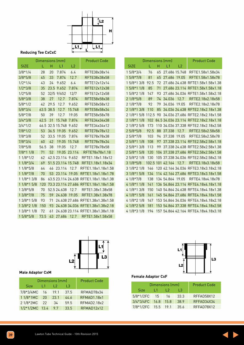
Lawton Tube Technical Guide - 10th Revision 2015
Reducing Tee CxCxCL1 L1
L2
L
H
Dimensions (mm) Product Code SIZE L H L1 L2
Dimensions (mm) Product Code SIZE L H L1 L2
3/8*1/4 28 20 7.874 6.4 RFTE38x38x14 3/8*5/8 45 33 7.874 12.7 RFTE38x38x58 1/2*1/4 43 24 9.652 6.4 RFTE12x12x14 1/2*3/8 35 23.5 9.652 7.874 RFTE12x12x38 1/2*5/8 52 32/5 9/652 12/7 RFTE12x12x58 5/8*3/8 38 27 12.7 7.874 RFTE58x58x38 5/8*1/2 42 29.5 12.7 9.652 RFTE58x58x12 5/8*3/4 63.5 38.5 12.7 15.748 RFTE58x58x34 5/8*7/8 50 39 12.7 19.05 RFTE58x58x78 3/4*3/8 42.5 31 15.748 7.874 RFTE34x34x38 3/4*1/2 46.5 32.5 15.748 9.652 RFTE34x34x12 7/8*1/2 53 36.5 19.05 9.652 RFTE78x78x12 7/8*3/8 52 33.5 19.05 7.874 RFTE78x78x38 7/8*3/4 60 42 19.05 15.748 RFTE78x78x34 7/8*5/8 56.5 38 19.05 12.7 RFTE78x78x58 7/8*1 1/8 71 52 19.05 23.114 RFTE78x78x1.18 1 1/8*1/2 62 42.5 23.114 9.652 RFTE1.18x1.18x12 1 1/8*3/4 69 51.5 23.114 15.748 RFTE1.18x1.18x34 1 1/8*5/8 64 46 23.114 12.7 RFTE1.18x1.18x1.58 1 1/8*7/8 70 53 23.114 19.05 RFTE1.18x1.18x1.78 1 1/8*1 3/8 86 63.5 23.114 24.638 RFTE1.18x1.18x1.38 1 1/8*1 5/8 120 73.3 23.114 27.686 RFTE1.18x1.18x1.58 1 3/8*5/8 70 52.5 24.638 12.7 RFTE1.38x1.38x58 1 3/8*7/8 75 59 24.638 19.05 RFTE1.38x1.38x78 1 3/8*1 5/8 93 71 24.638 27.686 RFTE1.38x1.38x1.58 1 3/8*2 1/8 150 93 24.638 34.036 RFTE1.38x1.38x2.18 1 3/8*1 1/8 72 61 24.638 23.114 RFTE1.38x1.38x1.18 1 5/8*5/8 73.5 63 27.686 12.7 RFTE1.58x1.58x58
1 5/8*3/4 76 65 27.686 15.748 RFTE1.58x1.58x34 1 5/8*7/8 81 65 27.686 19.05 RFTE1.58x1.58x78 1 5/8*1 3/8 92.5 72 27.686 24.638 RFTE1.58x1.58x1.38 1 5/8*1 1/8 85 71 27.686 23.114 RFTE1.58x1.58x1.18 1 5/8*2 1/8 147 93 27.686 34.036 RFTE1.58x1.58x2.18 2 1/8*5/8 89 74 34.036 12.7 RFTE2.18x2.18x58 2 1/8*7/8 92 79 34.036 19.05 RFTE2.18x2.18x78 2 1/8*1 3/8 110 85 34.036 24.638 RFTE2.18x2.18x1.38 2 1/8*1 5/8 112.5 90 34.036 27.686 RFTE2.18x2.18x1.58 2 1/8*1 1/8 102 84.5 34.036 23.114 RFTE2.18x2.18x1.18 2 1/8*2 5/8 173 110 34.036 37.338 RFTE2.18x2.18x2.582 5/8*5/8 92.5 88 37.338 12.7 RFTE2.58x2.58x58 2 5/8*7/8 103 94 37.338 19.05 RFTE2.58x2.58x78 2 5/8*1 1/8 108 97 37.338 23.114 RFTE2.58x2.58x1.18 2 5/8*1 3/8 113 99 37.338 24.638 RFTE2.58x2.58x1.38 2 5/8*1 5/8 120 104 37.338 27.686 RFTE2.58x2.58x1.58 2 5/8*2 1/8 130 105 37.338 34.036 RFTE2.58x2.58x2.18 3 1/8*5/8 102.5 101 42.164 12.7 RFTE3.18x3.18x58 3 1/8*2 1/8 146 120 42.164 34.036 RFTE3.18x3.18x2.18 3 1/8*1 5/8 134 114 42.164 27.686 RFTE3.18x3.18x1.58 4 1/8*7/8 138 134 54.864 19.05 RFTE4.18x4.18x78 4 1/8*1 1/8 141 136 54.864 23.114 RFTE4.18x4.18x1.18 4 1/8*1 3/8 150 140 54.864 24.638 RFTE4.18x4.18x1.38 4 1/8*1 5/8 161 145 54.864 27.686 RFTE4.18x4.18x1.58 4 1/8*2 1/8 167 153 54.864 34.036 RFTE4.18x4.18x2.18 4 1/8*2 5/8 181 153 54.864 37.338 RFTE4.18x4.18x2.58 4 1/8*3 1/8 194 157 54.864 42.164 RFTE4.18x4.18x3.18
39
Male Adaptor CxM
L1
L2L3
Dimensions (mm) Product Code Size L1 L2 L3
7/8*3/4MC 16 19.1 37.5 RFMAD78x34 1 1/8*1MC 20 23.1 44.6 RFMAD1.18x1 2 1/8*2MC 22 34 59.5 RFMAD2.18x2 1/2*1/2MC 13.4 9.7 33.5 RFMAD12x12
Female Adaptor CxF
L1
L2
L3
Dimensions (mm) Product Code Size L1 L2 L3
5/8*1/2FC 15 16 33.3 RFFAD58X12 3/4*3/4FC 16.8 15.8 38.9 RFFAD34X34 7/8*1/2FC 15.5 19.1 35.6 RFFAD78X12

Lawton Tube Technical Guide - 10th Revision 2015
Reducing tee One End and branch H1 H2
H3
L1
L2L3
Dimensions (mm) Product Code SIZE H1 H2 H3 L1 L2 L3
1/2*3/8*3/8 16.5 20.5 24.5 9.652 7.874 7.874 RFTE12X38X38 1/2*3/8*1/2 18 22 25 9.652 7.874 9.652 RFTE12X38X12 5/8*3/8*3/8 19 22 27 12.7 7.874 7.874 RFTE58X38X38 5/8*1/2*3/8 19 21.5 27 12.7 9.652 7.874 RFTE58X12X38 5/8*1/2*1/2 21.5 23.5 29.5 12.7 9.652 9.652 RFTE58X12X12 3/4*5/8*5/8 26 27 35.5 15.748 12.7 12.7 RFTE34X58X58 7/8*1/2*1/2 26.5 31 31 19.05 9.652 9.652 RFTE78X12X12 7/8*1/2*7/8 31.5 36 44.5 19.05 9.652 19.05 RFTE78X12X78 7/8*5/8*1/2 28 29.5 31 19.05 12.7 9.652 RFTE78X58X12 7/8*5/8*7/8 31.5 35 44.5 19.05 12.7 9.652 RFTE78X58X78 7/8*3/4*3/4 31 34 43 19.05 15.748 15.748 RFTE78X34X34 7/8*5/8*5/8 28 30 38.5 19.05 12.7 12.7 RFTE78X58X58 1 1/8*5/8*5/8 33 35 46 23.114 12.7 12.7 RFTE1.18X58X58 1 1/8*5/8*7/8 35.5 40 52 23.114 19.05 19.05 RFTE1.18X58X78 1 1/8*5/8*1 1/8 39 42 57 23.114 12.7 23.114 RFTE1.18X58X1.18 1 1/8*7/8*7/8 35 42 52 23.114 19.05 19.05 RFTE1.18X78X78 1 1/8*7/8*1 1/8 39 46 57 23.114 19.05 23.114 RFTE1.18X78X1.18 1 1/8*7/8*5/8 32 39 46 23.114 19.05 12.7 RFTE1.18X78X58 1 1/8*7/8*1/2 30.5 38 42.5 23.114 19.05 9.652 RFTE1.18X78X12 1 3/8*5/8*1 3/8 43 54 64.5 24.638 12.7 24.638 RFTE1.38X58X1.38 1 3/8*7/8*5/8 35 45 52.5 24.638 19.05 12.7 RFTE1.38X78X58 1 3/8*7/8*7/8 38 51.5 59 24.638 19.05 19.05 RFTE1.38X78X78 1 3/8*7/8*1 3/8 43 58 64.5 24.638 19.05 24.638 RFTE1.38X78X1.38 1 3/8*1 1/8*7/8 37 45 57 24.638 23.114 19.05 RFTE1.38X1.18X78 1 3/8*1 1/8*5/8 34 44 53.5 24.638 23.114 12.7 RFTE1.38X1.18X58 1 3/8*1 1/8*1 1/8 41 49 57 24.638 23.114 23.114 RFTE1.38X1.18X1.18 1 5/8*7/8*7/8 40 54 67 27.686 19.05 19.05 RFTE1.58X78X78 1 5/8*7/8*1 5/8 50 60 76 27.686 19.05 27.686 RFTE1.58X78X1.58 1 5/8*1 1/8*7/8 41 53.5 66.5 27.686 23.114 19.05 RFTE1.58X1.18X78 1 5/8*1 1/8*1 1/8 42.5 52.5 71 27.686 23.114 23.114 RFTE1.58X1.18X1.18 1 5/8*1 1/8*1 3/8 48 56 72.5 27.686 23.114 24.638 RFTE1.58X1.18X1.38 1 5/8*1 1/8*1 5/8 51 59 75 27.686 23.114 27.686 RFTE1.58X1.18X1.58 1 5/8*1 3/8*1 3/8 42.5 55 72.5 27.686 24.638 24.638 RFTE1.58X1.38X1.38 1 5/8*1 3/8*1 5/8 51.5 59.5 75 27.686 24.638 27.686 RFTE1.58X1.38X1.58 2 1/8*1 1/8*1 1/8 50 64 84.5 34.036 23.114 23.114 RFTE2.18X1.18X1.18 2 1/8*1 3/8*7/8 47.5 61.5 79 34.036 24.638 19.05 RFTE2.18X1.38X78 2 1/8*1 3/8*1 1/8 50 63 87 34.036 24.638 23.114 RFTE2.18X1.38X1.18 2 1/8*1 3/8*1 3/8 54 69 85 34.036 24.638 24.638 RFTE2.18X1.38X1.38 2 1/8*1 3/8*2 1/8 63 75 92 34.036 24.638 34.036 RFTE2.18X1.38X2.18 2 1/8*1 5/8*1 1/8 50 61 84 34.036 27.686 23.114 RFTE2.18X1.58X1.18 2 1/8*1 5/8* 7/8 48 61 77.5 34.036 27.686 19.05 RFTE2.18X1.58X78 2 1/8*1 5/8*1 3/8 54 65 85.5 34.036 27.686 24.638 RFTE2.18X1.58X1.38 2 1/8*1 5/8*1 5/8 56.5 63.5 89 34.036 27686 27.686 RFTE2.18X1.58X1.58 2 5/8*7/8*2 5/8 73.5 88 112 37.338 19.05 37.338 RFTE2.58X78X2.58 2 5/8*2 1/8*1 5/8 61.5 73 101 37.338 34.036 27.686 RFTE2.58X2.18X1.58 2 5/8*2 1/8*2 1/8 67.5 78.5 105.5 37.338 34.036 34.036 RFTE2.58X2.18X2.18 3 1/8*2 1/8*2 1/8 72 88 123 42.164 34.036 34.036 RFTE3.18X2.18X2.18 3 1/8*2 5/8*1 5/8 70 77 121 42.164 34.036 27.686 RFTE3.18X2.58X1.58 3 1/8*2 5/8*2 1/8 71.5 83.5 123 42.164 37.338 34.036 RFTE3.18X2.58X2.18
40

Lawton Tube Technical Guide - 10th Revision 2015
P-Trap
L2L1
L4
L3
Dimensions (mm) Product Code SIZE L1 L2 L3 L4
3/8 87.2 35.1 95.2 38.1 RFPT38 1/2 64 73.2 42.6 43.2 RFPT12 5/8 80.2 94.8 55.6 57.2 RFPT58 3/4 134.1 152.4 73 76.2 RFPT34 7/8 133.4 142.9 69.85 76.2 RFPT78 1 1/8 125 134.1 55.2 89.7 RFPT1.18 1 3/8 133.4 177.6 88.9 127 RFPT1.38 1 5/8 196.8 223.8 88.9 127 RFPT1.58 2 1/8 219 250.8 104.8 152.4 RFPT2.18
Tube Strap - Double Hole
L2L1
L3
H
Dimensions (mm) Product Code SIZE L1 L2 L3 H
1/2 33.5 46 13 14.2 6.6 RFSPS12 5/8 36 53 13 16.5 8 RFSPS58 3/4 40.2 53.3 13 20.2 9.6 RFSPS34 7/8 44 61.5 13 22.5 11.3 RFSPS78 1 1/8 48.8 67 13 30.5 14 RFSPS1.18 1 3/8 58 71 13 36.5 17.8 RFSPS1.38 1 5/8 62 74 12.8 42 21 RFSPS1.58 2 1/8 79.3 91.7 13 55.5 27.25 RFSPS2.18
41
90deg Long Radius Elbow
L
H
Dimensions (mm) Product Code Size H L
1/4 19 6.4 RFELLR14 3/8 23.5 7.874 RFELLR38 1/2 27.8 9.652 RFELLR12 5/8 34 12.7 RFELLR58 3/4 41.5 15.748 RFELLR34 7/8 50.8 19.05 RFELLR78 1 1/8 62.5 23.114 RFELLR1.18 1 3/8 73.6 24.638 RFELLR1.38 1 5/8 84 27.686 RFELLR1.58 2 1/8 110 34.036 RFELLR2.18 2 5/8 131.5 37.338 RFELLR2.58 3 1/8 165 42.164 RFELLR3.18 3 5/8 193 48.514 RFELLR3.58 4 1/8 217 54.864 RFELLR4.18
L
H
Dimensions (mm) Product Code Size H L
1/4 14.6 6.4 RFELSR14 3/8 16.9 7.874 RFELSR38 1/2 19.5 9.652 RFELSR12 5/8 22.6 12.7 RFELSR58 3/4 28.5 15.748 RFELSR34 7/8 33.8 19.05 RFELSR78 1 40 23.1 RFELSR1 1 1/8 41.8 23.114 RFELSR1.18 1 3/8 47 24.638 RFELSR1.38 1 5/8 53.5 27.686 RFELSR1.58 2 1/8 66 34.036 RFELSR2.18 2 5/8 79.6 37.338 RFELSR2.58 3 1/8 98 42.164 RFELSR3.18 3 5/8 111 48.514 RFELSR3.58 4 1/8 120 54.864 RFELSR4.18
90deg Short Radius Elbow

Lawton Tube Technical Guide - 10th Revision 2015
Brazing Rods
Type of Product
5% Silver Brazing Alloy
Composition
5% Silver
89% Copper
6% Phosphorous
Impurities to BSEN 17672 Group CP
Alloy conforms to BSEN 17672:2010 CuP104
Melting Range
645 - 815oC
Appearance
Copper coloured metal
Occupational Health Data
TLV
Odour threshold
Silver 0.1mg/m3 as fume
Phosphorous 1mg/m3 as phosphoric acid
Copper 0.2mg/m3 as fume
Working Temp
710oC
Tensile Strength 600N/mm2
Hardness 190
Elongation 7%
Electrical Conductivity 10% I.A.C.S. at 20oC
Type of Product
2% Silver Brazing Alloy
Composition
2% Silver
91.7% Copper
6.3% Phosphorous
Impurities to BSEN 17672 Group CP
Alloy conforms to BSEN 17672:2010 CuP104
Melting Range
645 - 825oC
Appearance
Copper coloured metal
Occupational Health Data
TLV
Odour threshold
Silver 0.1mg/m3 as fume
Phosphorous 1mg/m3 as phosphoric acid
Copper 0.2mg/m3 as fume
Working Temp
740oC
Tensile Strength 490N/mm2
Hardness 195
Elongation 5%
Electrical Conductivity 9% I.A.C.S. at 20oC
Type of Product
Square 0.2% Silver Brazing Alloy
Composition
0.2% Silver
93.5% Copper
6.3% Phosphorous
Impurities to BSEN 17672 Group CP
Alloy conforms to BSEN 17672:2010 CuP104
Melting Range
645 - 815oC
Appearance
Copper coloured metal
Occupational Health Data
TLV
Odour threshold
Silver 0.1mg/m3 as fume
Phosphorous 1mg/m3 as phosphoric acid
Copper 0.2mg/m3 as fume
Working Temp
760oC
Tensile Strength 490N/mm2
Hardness 195
Elongation 5%
Electrical Conductivity 8.5% I.A.C.S. at 20oC
42

Lawton DualBimetallic seamless round composite copper and aluminium tubes for HVAC&R applications
Material:
Seamless composite round tubes made of high purity copper and aluminium outer, supplied in Level Wound Coils, PNC Coils, Pre-insulated Bunch Coils and Straight lengths. Produced in accordance to product specification TB 01 and in compliance to EN 12735-1 regarding internal residue.
Annealed Temper - Mechanical Properties:
o Tensile Strength (Rm) > 100 N/mm2
o Yield Strength (Rp0.2) > 40 N/mm2
o Elongation (A50mm) > 30 %
Mechanical Properties
Surface Quality & Cleanliness
Tubes are bright and smooth, free from cracks, slivers, seams, scales and other surface defects. The maximum residue on the inner surface of the tube is 0.38 mg/dm2. The ends of each tube are closed to prevent any contamination of the inner surface.
Freedom and Identification of Defects - Eddy Current Testing
The tubes are 100 % tested in an eddy current unit capable of detecting any defect detrimental to subsequent processing or the end use of the tube.
Drift Expanding
The outside diameter of the tube end can be expanded by at least 40%.
Internal Working Pressure
The tubes can endure at least a maximum internal working pressure of 5,5 MPa (55 Bar) at temperatures up to 120 ˚C with an actual burst pressure above 22 MPa (220 Bar). Safety Factor of 4 / Factor of Safety (FoS) 4:1
Inspection Document
An inspection document / a mill test certificate according to EN 10204 / 3.1 or a Declaration of Conformity can be supplied with each dispatch.
Wall (mm) 0.80 0.80 1.00 1.20
O.D. (inches)
1/4 3/8 1/2 5/8
Mean Outside Combined Wall Thickness Diameter (mm) at any point ± 0.04 ± 10% ± 0.04 ± 10% ± 0.04 ± 13% ± 0.05 ± 13%
Dimensions Tolerances
O.D. (mm) 6.35 9.52
12.70 15.87
43 Lawton Tube Technical Guide - 9th Revision 2014

Lawton Tube Technical Guide - 10th Revision 2015
Dual SolderNon Corrosive Flux Cored Zinc-Aluminium Alloy
Nominal Composition
Al 22 % ± 1
Zn SOLDE
Cd 0,005 % MAX
Pb 0,005 % MAX
Others Cd, Pb included 0,15 % MAX
Melting Point
Melting range : 415-475°C
Available On
Wires
Coils
Black Spools SD 300K of 5 kg
Rods Length : 13,0’’ – 19,7’’ – 29,6’’ – 39,4’’) packaged on 100g/250g/500g/1000g
Preform shapes
Rings
Diameters Available
0,047’’- 0,063’’- 0,079’’
other diameters could be done
Utilisations
Low temperature alloy for brazing aluminium and its alloys – Stainless steel, Steel, Copper.
Composition Of The Flux
Non corrosives fluorides of caesium are the mainly compounds of the flux.
Amount of flux is 5 to 40% of total weight
44

Lawton Tube Technical Guide - 10th Revision 201545
Lawton K65 Lawton K65 is a high copper alloy with high mechanical strength.
Typical ApplicationsTubes for air conditioning and refrigeration, heating and solar engineering, brake line tubing
Material designationEN CuFe2P CW1076UNS* C19400* Unified numbering system
Physical Properties*Thermal Conductivity W/(m-K) >260DensityG/CM3 8.91 *Reference values at room temperature
Temper (DIN EN12449)R300** soft annealedR420** hard
According to DIN EN 12449Chemical Composition Mechanical properties (annealed)
Fe 2.10-2.60 % Rn min.>300 N/mm2Zn 0.05-0.20% Rn max.>250 N/mm2P 0.015-0.15 % A min. >25%Pb max. 0.03 %Cu balance**Conformity to PED 97/23/EC can be certified through product inspection by a technical inspection agency such as TUV.
Fabrication properties Joining
Cold working excellent Brazing excellent Electroplating excellent Soft soldering excellent Hot-dip tinning excellent Inert gas shieldedMachinability poor arc welding excellent Resistance welding good Laser welding good
Sizes availableType of delivery Outside diameter mm* Manufacture Temper Straight lengths plain 7-108 seamless hard or annealed(max. 7800 mm) inner-grooved 7-16 seamless hard or annealedLevel-wound coils (LWC) plain 7-20 seamless hard or annealed(coil weight on request) inner-grooved 7-16 seamless hard or annealed*Wall thicknesses and other sizes on request
Relevant standards and specificationsDIN EN 12449 Seamless, round tubes for general purposesWieland R-1084 Seamless drawn plain or inner-grooved tubes in K65 in LWC for pressure vesels and pipingWieland R-1085 Seamless drawn plain or inner-grooved copper tubes in K65 in straight lengths for pressure vessels and pipingVdTUV-Werkstoffblatt, new draft 03.2010 Seamless drawn tubes in CuFe2P (CW107C) Wieland K65
Corrosion resistanceLawton K65 is insensitive to stress corrosion cracking. Lawton K65 exhibits good resistance in natural atmosphere (also marine atmosphere) and industrial atmosphere. It has a better resistance to erosion and pitting corrosion than Cu-DHP in different types of water and neutral saline solutions.
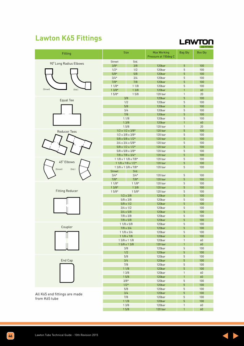
Lawton Tube Technical Guide - 10th Revision 2015
Lawton K65 Fittings
46
All K65 end fittings are made from K65 tube
Fitting
90o Long Radius Elbows
(Street) (Std.)
(Street) (Std.)
Equal Tee
Fitting Reducer
Coupler
End Cap
Reducer Tees
45o Elbows
Size Max Working Bag Qty Box Qty Pressure at 150deg C
Street Std. 3/8* 3/8 120bar 5 100 1/2* 1/2 120bar 5 100 5/8* 5/8 120bar 5 100 3/4* 3/4 120bar 5 100 7/8* 7/8 120bar 5 100 1 1/8* 1 1/8 120bar 5 100 1 3/8* 1 3/8 120bar 1 60 1 5/8* 1 5/8 120 bar 1 20 3/8 120bar 5 100 1/2 120bar 5 100 5/8 120bar 5 100 3/4 120bar 5 100 7/8 120bar 5 100 1.1/8 120bar 5 100 1.3/8 120bar 1 60 1.5/8 120 bar 1 20 1/2 x 1/2 x 3/8* 120 bar 5 100 1/2 x 3/8 x 3/8* 120 bar 5 100 5/8 x 5/8 x 1/2* 120 bar 5 100 3/4 x 3/4 x 5/8* 120 bar 5 100 5/8 x 1/2 x 1/2* 120 bar 5 100 5/8 x 5/8 x 3/8* 120 bar 5 100 7/8 x 7/8 x 3/4* 120 bar 5 100 1 1/8 x 1 1/8 x 7/8* 120 bar 5 100 1 1/8 x 7/8 x 1/2* 120 bar 5 100 1 3/8 x 1 3/8 x 7/8* 120 bar 5 100 Street Std. 3/4* 3/4* 120 bar 5 100 7/8* 7/8* 120 bar 5 100 1 1/8* 1 1/8* 120 bar 5 100 1 3/8* 1 3/8 120 bar 5 100 1 5/8* 1 5/8* 120 bar 5 100 1/2 x 3/8 120bar 5 100 5/8 x 3/8 120bar 5 100 5/8 x 1/2 120bar 5 100 3/4 x 1/2 120bar 5 100 3/4 x 5/8 120bar 5 100 7/8 x 3/8 120bar 5 100 7/8 x 5/8 120bar 5 100 1 1/8 x 5/8 120bar 5 100 7/8 x 3/4 120bar 5 100 1 1/8 x 3/4 120bar 5 100 1 1/8 x 7/8 120bar 5 100 1 3/8 x 1 1/8 120bar 1 60 1 5/8 x 1 3/8 120 bar 1 60 3/8 120bar 5 100 1/2 120bar 5 100 5/8 120bar 5 100 3/4 120bar 5 100 7/8 120bar 5 100 1 1/8 120bar 5 100 1 3/8 120bar 1 60 1 5/8 120bar 1 60 3/8* 120bar 5 100 1/2* 120bar 5 100 5/8 120bar 5 100 3/4 120bar 5 100 7/8 120bar 5 100 1 1/8 120bar 5 100 1 3/8 120bar 1 60 1 5/8 120 bar 1 60

Lawton Tube Technical Guide - 10th Revision 2015
Kitemark – BS EN 1057
This Licence remains the property of The British Standards Institution and shall be returned immediately upon request. To check its validity telephone +44 (0)845 080 9000
Information and contact: BSI, Kitemark Court, Davy Avenue, Knowlhill, Milton Keynes MK5 8PP. Tel: +44 845 080 9000. BSI Assurance UK Limited, registered inEngland under number 7805321, at 389 Chiswick High Road, London, W4 4AL, UK. A member of the BSI Group of Companies.
No. KM 05892
First Issued: 1/11/1974 Latest Issue: 14/05/2012
Page 2 of 3
BS EN 1057 – Copper and copper alloys
1. Certified Product Range:
R250 Half-Hard
OutsideDiameter (mm)
WallThickness (mm)
6 0.66 0.88 0.68 0.810 0.610 0.812 0.612 0.815 0.715 1.022 0.922 1.228 0.928 1.235 1.235 1.542 1.242 1.554 1.254 2.0
This Licence remains the property of The British Standards Institution and shall be returned immediately upon request. To check its validity telephone +44 (0)845 080 9000
Information and contact: BSI, Kitemark Court, Davy Avenue, Knowlhill, Milton Keynes MK5 8PP. Tel: +44 845 080 9000. BSI Assurance UK Limited, registered inEngland under number 7805321, at 389 Chiswick High Road, London, W4 4AL, UK. A member of the BSI Group of Companies.
No. KM 05892
First Issued: 1/11/1974 Latest Issue: 14/05/2012
Page 3 of 3
1. Certified Product Range (continued)
R290 Hard
OutsideDiameter (mm)
WallThickness (mm)
35 1.035 1.542 1.042 1.554 1.054 1.254 2.0
66.7 1.266.7 2.076 1.576 2.0108 1.5108 2.5133 1.5159 2.0219 3.0
2. Product Marking:
BS EN 1057. . LAWTON . O/D . WALL|-|-|. MONTH .YEAR
47
This Licence remains the property of The British Standards Institution and shall be returned immediately upon request. To check its validity telephone +44 (0)845 080 9000
Information and contact: BSI, Kitemark Court, Davy Avenue, Knowlhill, Milton Keynes MK5 8PP. Tel: +44 845 080 9000. BSI Assurance UK Limited, registered in
England under number 7805321, at 389 Chiswick High Road, London, W4 4AL, UK. A member of the BSI Group of Companies.
No. KM 05892
First Issued: 1/11/1974 Latest Issue: 14/05/2012
Page 1 of 3
This Licence remains the property of The British Standards Institution and shall be returned immediately upon request. To check its validity telephone +44 (0)845 080 9000
Information and contact: BSI, Kitemark Court, Davy Avenue, Knowlhill, Milton Keynes MK5 8PP. Tel: +44 845 080 9000. BSI Assurance UK Limited, registered in
England under number 7805321, at 389 Chiswick High Road, London, W4 4AL, UK. A member of the BSI Group of Companies.
The licence is granted to:The Lawton Tube Company LimitedTorrington AvenueCoventryWest MidlandsCV4 9ABUnited Kingdom
No. KM 05892
In respect of:BS EN 1057Copper and copper alloys. Seamless, round copper tubes for water and gas in sanitary
and heating applications This issues the right and licence to use the Kitemark in accordance with the Kitemark Licence Conditions of
Contract governing the use of the Kitemark, as may be updated from time to time by The British Standards
Institution, and as approved by the Registrar under the Trade Marks Act 1994 (the "Conditions"). All defined terms
in this Licence shall have the same meaning as in the Conditions.The use of the Kitemark is authorized in respect of the Product(s) detailed on this Licence provided at or from the
above address.
For and on behalf of BSI:
First Issued: 1/11/1974 Latest Issue: 14/05/2012
Page 1 of 3
Gary Fenton, Global Assurance Director

Lawton Tube Technical Guide - 10th Revision 2015
CE Mark Cert – EN 1057
48

Lawton Tube Technical Guide - 10th Revision 2015
Kitemark – IS EN 1057
49
Kitemark – BS EN13348

Lawton Tube Technical Guide - 10th Revision 2015
Water Regulations Advisory Scheme
50

Lawton Tube Technical Guide - 10th Revision 2015
Affiliation Certificates
51
Quality System ISO 9001:2008

Lawton Tube Technical Guide - 10th Revision 2015
30 Year Guarantee Enjoy the added bonus of an extra 5 year warranty with no additional premiums if Lawton’s EN1057 15-219mm range is fitted with any flame-free jointed piping system. (contact us for full terms and conditions)
52
25 Year Guarantee
The Lawton Tube Company Limited (“Lawton”) guarantees its plain copper tubes and its
copper end feed fittings for water, heating, gas and sanitation purposes, for the period of
25 years from the date of purchase, against fault or defect due to defective materials or
manufacture or failure to comply with the provision of the quality stamped on the tube/
fitting.
If any tube/fitting shall fail this guarantee Lawton shall:
• Replace the faulty tube/fitting
• Pay the installer’s costs of removing or replacing the faulty tube/fitting
(up to an amount of £75,000 per claim.)
• Pay any costs or damages suffered/incurred as a result of the failure
(up to an amount of £250,000 per claim.)
Lawton reserves the right to remedy the failure itself or by its own nominated contractor.
_____________________
Oliver Lawton, Managing Director
Conditions This guarantee is conditional upon: Proper installation of the tube/fitting in accordance with all relevant practices and regulations. Lawton being notified of the failure as soon as practicable but in any event within 14 days after the failure. The claimant taking all appropriate or necessary measures to mitigate the damages or losses suffered. Lawton being given the opportunity to inspect the faulty tube and the installation (with or without its own experts) to satisfy itself as to the failure of the tube, and if required to remove the faulty tube/fitting for testing. Lawton having no liability for any indirect or consequential losses. Lawton’s total liability under this guarantee not exceeding the sum of £250,000. This guarantee extends only to the original purchaser/installer of the tube/fitting and is not capable of assignment and applies only to the tube/fitting sold and installed in the United Kingdom.
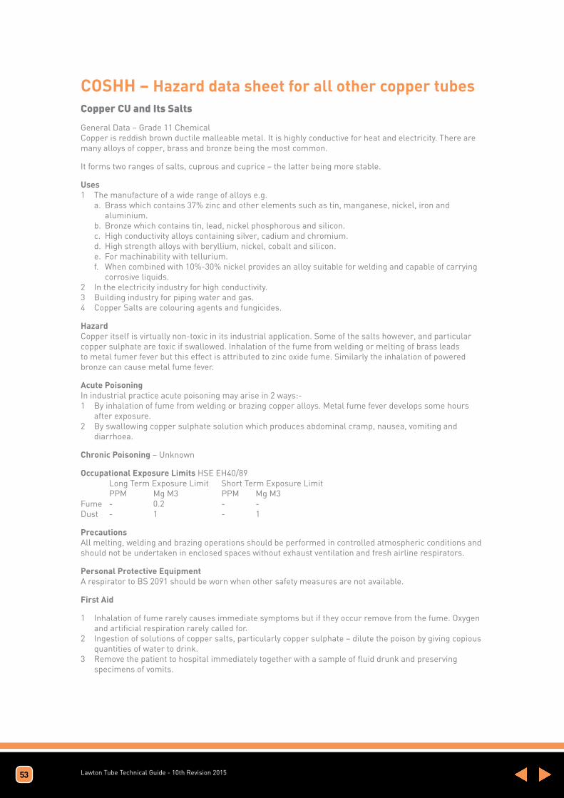
Lawton Tube Technical Guide - 10th Revision 2015
COSHH – Hazard data sheet for all other copper tubesCopper CU and Its Salts
General Data – Grade 11 Chemical Copper is reddish brown ductile malleable metal. It is highly conductive for heat and electricity. There are many alloys of copper, brass and bronze being the most common.
It forms two ranges of salts, cuprous and cuprice – the latter being more stable.
Uses 1 The manufacture of a wide range of alloys e.g. a. Brass which contains 37% zinc and other elements such as tin, manganese, nickel, iron and aluminium. b. Bronze which contains tin, lead, nickel phosphorous and silicon. c. High conductivity alloys containing silver, cadium and chromium. d. High strength alloys with beryllium, nickel, cobalt and silicon. e. For machinability with tellurium. f. When combined with 10%-30% nickel provides an alloy suitable for welding and capable of carrying corrosive liquids. 2 In the electricity industry for high conductivity. 3 Building industry for piping water and gas. 4 Copper Salts are colouring agents and fungicides.
Hazard Copper itself is virtually non-toxic in its industrial application. Some of the salts however, and particular copper sulphate are toxic if swallowed. Inhalation of the fume from welding or melting of brass leads to metal fumer fever but this effect is attributed to zinc oxide fume. Similarly the inhalation of powered bronze can cause metal fume fever.
Acute Poisoning In industrial practice acute poisoning may arise in 2 ways:- 1 By inhalation of fume from welding or brazing copper alloys. Metal fume fever develops some hours after exposure. 2 By swallowing copper sulphate solution which produces abdominal cramp, nausea, vomiting and diarrhoea.
Chronic Poisoning – Unknown
Occupational Exposure Limits HSE EH40/89 Long Term Exposure Limit Short Term Exposure Limit PPM Mg M3 PPM Mg M3 Fume - 0.2 - - Dust - 1 - 1
Precautions All melting, welding and brazing operations should be performed in controlled atmospheric conditions and should not be undertaken in enclosed spaces without exhaust ventilation and fresh airline respirators.
Personal Protective Equipment A respirator to BS 2091 should be worn when other safety measures are not available.
First Aid
1 Inhalation of fume rarely causes immediate symptoms but if they occur remove from the fume. Oxygen and artificial respiration rarely called for. 2 Ingestion of solutions of copper salts, particularly copper sulphate – dilute the poison by giving copious quantities of water to drink. 3 Remove the patient to hospital immediately together with a sample of fluid drunk and preserving specimens of vomits.
53

Lawton Tube Technical Guide - 10th Revision 2015
Company Environmental Policy The Lawton Tube Company Limited is the UK’s leading independent supplier of copper tube and fittings. We form an indispensable link between one of the world’s most versatile metals and a wide variety of finished goods.
We recognise and understand that our business activities, products and services have an effect on the local, regional and the global environment.
As a consequence of this our business is committed to identifying our environmental hazards and risks and to manage them effectively by implementing and maintaining an environmental management system (EMS).
The scope of our EMS covers the manufacture and distribution of solid drawn copper alloy tubes to national, international standards, customer own specifications and the supply of refrigeration tubes and fittings and medical fittings.
Our environmental commitments are to:
• Implement and maintain an Environmental Management System (EMS) ISO14001.
• Comply with applicable environmental legal and other requirements which relate to the businesses environmental hazards and risks (aspects).
• Have a process for setting, monitoring and improving environmental objectives and targets.
• To encourage an ethos of preventing pollution, reducing waste and minimise the consumption of resources where practical.
• Educate, train and motivate employees to carry out tasks in an environmentally responsible manner.
• Encourage environmental protection and best practice among suppliers and subcontractors.
• The business is committed to continual improvement of environmental performance. This Policy will be communicated to all staff, and those who work for or on its behalf. The policy will also be made available to the public.
Health & Safety Policy The Lawton Tube Co. Ltd recognises Health and Safety issues are an integral part of our business, and we are committed to ensuring the Health and Safety of all persons likely to be affected by activities on our premises. These include our employees, customers, contractors and self-employed persons working on our site, and visitors.
Our aim is to improve and promote health and safety at work throughout the organization, by using appropriate systems to implement the Health and Safety policy, its objectives and suitable safeguard arrangements.
The Managers and Employees are committed to the health and safety policy, and improving the health and safety performance of our business.
The policy is expressed in ‘Key Commitments’ that set the standards and practices that our businesses shall employ, in addressing health and safety issues.
All employees have a legal duty and obligation to co-operate, be involved and committed to ensuring the health and safety policy, objectives and safety arrangements are complied with for themselves and others.
The scope of the OH&S management system includes:
The scope of the OHSAS management system is covered by the company processes in section 4.1a which contributes to the manufacture and distribution of copper tube and fittings from the two company sites at Coventry and Poole.
54

Lawton Tube Technical Guide - 10th Revision 2015
KEY COMMITMENTS
1. Comply with relevant national Health and Safety Legislation & other requirements. • Identify and conform to, if not exceed, all current and applicable health and safety legislations and regulations and other requirements to which the business subscribes.
2. Keep up to date with developments in Health and Safety • Identify developments in health and safety and ensure these are integrated into the safety arrangements.
3. Identify and assess all significant risks to Health and Safety • Define and implement a formal programme of risk assessments.
4. Eliminate or introduce measures to adequately control these Risks • Establish a systematic approach to the identification of significant hazards, risk assessments and the allocation of resources to eliminate and or control these hazards. • Provide a safe and healthy working environment and implement appropriate measures to prevent accidents and incidents occurring.
5. Put in place appropriate Health and Safety Policies and Procedures • Introduce formal systems (i.e. OHSAS 18001) to implement the health and safety policy, objectives and arrangements.
6. Provide adequate resources to ensure our Policies and Procedures are implemented. • Provide sufficient resources to fulfil legal obligations.
7. Involve and consult with our employees • Establish a culture of employee involvement and cooperation to address issues affecting their health and safety.
8. Ensure all employees are informed of our Policies and Procedures • Promote health and safety awareness at all levels of management and throughout the Company.
9. Ensure all employees comply with our Safety Policies and Procedures • Clearly define health and safety responsibilities of all personnel and communicate these throughout the Company. • All employees have a legal duty and obligation to co-operate, be involved and committed to ensuring the health and safety policy, objectives and safety arrangements are complied with. • Ensure contractors comply with the Health and Safety Rules and Procedures for Contractors’.
10. Carry out periodic review of our Safety Policies and Procedures • Complete planned health and safety audits to review and check the effectiveness of each sites’ management of the Health and Safety policy and arrangements.
11. Continually improve our Health and Safety performance • Monitor and improve safety performance alongside other management performance criteria. • Establish and maintain a ‘Safety Committee’ for discussing health and safety matters and identifying improvement opportunities. • Be committed to the prevention of injury and ill health.
55

The buyer’s attention is in particular drawn to the provisions of condition 12.4.
1. INTERPRETATION
1.1 The definitions and rules of interpretation in this condition apply in these conditions.
Buyer: The person, firm or company who purchases the Goods from the Company.
Company: The Lawton Tube Company Limited (CRN 00165130)
Contract: Any contract between the Company and the Buyer for the sale and purchase of the Goods, incorporating these conditions.
Delivery Point: The place where delivery of the Goods is to take place under condition 4.
Goods: Any goods agreed in the Contract to be supplied to the Buyer by the Company (including any part or parts of them).
1.2 A reference to a particular law is a reference to it as it is in force for the time being taking account of any amendment, extension, application or re-enactment and includes any subordinate legislation for the time being in force made under it.
1.3 Words in the singular include the plural and in the plural include the singular.
1.4 A reference to one gender includes a reference to the other gender.
1.5 Condition headings do not affect the interpretation of these conditions.
2. APPLICATION OF TERMS
2.1 Subject to any variation under condition 2.3 the Contract shall be on these conditions to the exclusion of all other terms and conditions (including any terms or conditions which the Buyer purports to apply under any purchase order, confirmation of order, specification or other document).
2.2 No terms or conditions endorsed on, delivered with or contained in the Buyer’s purchase order, confirmation of order, specification or other document shall form part of the Contract simply as a result of such document being referred to in the Contract.
2.3 These conditions apply to all the Company’s sales and any variation to these conditions and any representations about the Goods shall have no effect unless expressly agreed in writing and signed by a Director of the Company. The Buyer acknowledges that it has not relied on any statement, promise or representation made or given by or on behalf of the Company which is not set out in the Contract. Nothing in this condition shall exclude or limit the Company’s liability for fraudulent misrepresentation.
2.4 Each order or acceptance of a quotation for Goods by the Buyer from the Company shall be deemed to be an offer by the Buyer to buy Goods subject to these conditions.
2.5 No order placed by the Buyer shall be deemed to be accepted by the Company until a written acknowledgement of order is issued by the Company or (if earlier) the Company delivers the Goods to the Buyer.
2.6 The Buyer shall ensure that the terms of its order and any applicable specification are complete and accurate.
2.7 Any quotation is given on the basis that no Contract shall come into existence until the Company despatches an acknowledgement of order to the Buyer.
3. DESCRIPTION
3.1 The quantity and description of the Goods shall be as set out in the Company’s quotation or acknowledgement of order.
3.2 All samples, drawings, descriptive matter, specifications and advertising issued by the Company and any descriptions or illustrations contained in the Company’s catalogues or brochures are issued or published for the sole purpose of giving an approximate idea of the Goods described in them. They shall not form part of the Contract and this is not a sale by sample.
3.3 If the Goods are to be manufactured or any process is to be applied to the Goods by the Seller in accordance with a specification submitted by the Buyer:¬
(a) The Buyer shall supply such specification within sufficient time to enable the Company to complete delivery of the goods by the estimated delivery date.
(b) The Buyer shall indemnify the Company against all loss damages costs and expenses awarded against or incurred by the Company in connection with or paid or agreed to be paid by the Company in settlement of any claim for infringement of any patent, copyright, design, trade mark or other industrial or intellectual property rights of any other person which results from the Company’s use of the Buyer’s specification.
(c) The Company reserves the right to make any changes in the specification of the Goods which are required to conform with any applicable statutory or EC requirements.
(d) The Company shall be under no liability in respect of any defect in the Goods arising from any drawing design or other specification supplied by the Buyer
4. RAW MATERIALS AND SPECIAL TOOLS
4.1 Contracts and orders are accepted subject to the Company being able to obtain at all necessary times the raw materials and any special tools required to execute the order.
4.2 Any dies or tools made or obtained specially for an order remain the Seller’s property, even when the Buyer has been charged with the cost or part cost.
5. DELIVERY
5.1 Unless otherwise agreed in writing by the Company, delivery of the Goods shall take place at the Buyer’s place of business.
5.2 The Buyer shall take delivery of the Goods within 7 days of the Company giving it notice that the Goods are ready for delivery.
5.3 Any dates specified by the Company for delivery of the Goods are intended to be an estimate and time for delivery shall not be made of the essence by notice. If no dates are so specified, delivery shall be within a reasonable time.
5.4 Subject to the other provisions of these conditions the Company shall not be liable for any direct, indirect or consequential loss (all three of which terms include, without limitation, pure economic loss, loss of profits, loss of business, depletion of goodwill and similar loss), costs, damages, charges or expenses caused directly or indirectly by any delay in the delivery of the Goods (even if caused by the Company’s negligence), nor shall any delay entitle the Buyer to terminate or rescind the Contract.
5.5 If for any reason the Buyer fails to accept delivery of any of the Goods when they are ready for delivery, or the Company is unable to deliver the Goods on time because the Buyer has not provided appropriate instructions, documents, licences or authorisations:
(a) risk in the Goods shall pass to the Buyer (including for loss or damage caused by the Company’s negligence);
(b) the Goods shall be deemed to have been delivered; and
(c) the Company may store the Goods until delivery, whereupon the Buyer shall be liable for all related costs and expenses (including, without limitation, storage and insurance).
5.6 The Buyer shall provide at the Delivery Point and at its expense adequate and appropriate equipment and manual labour for unloading the Goods.
5.7 If the Company delivers to the Buyer a quantity of Goods of up to 10% more or less than the quantity ordered by the Buyer, the Buyer shall not be entitled to object to or reject the Goods or any of them by reason of the surplus or shortfall and shall pay for such goods at the pro rata Contract rate.
5.8 The Company may deliver the Goods by separate instalments. Each separate instalment shall be invoiced and paid for in accordance with the provisions of the Contract.
5.9 Each instalment shall be a separate Contract and no cancellation or termination of any one Contract relating to an instalment shall entitle the Buyer to repudiate or cancel any other Contract or instalment.
5.10 Where the Buyer has given firm instructions for the manufacture or delivery of Goods and subsequently requests the Seller to defer delivery, any Goods completed will be invoiced on completion, holding and storage charges at the reasonable cost of storage including delivery will be invoiced subsequently when applicable.
6. NON-DELIVERY
6.1 The quantity of any consignment of Goods as recorded by the Company on despatch from the Company’s place of business shall be conclusive evidence of the quantity received by the Buyer on delivery unless the Buyer can provide conclusive evidence proving the contrary.
6.2 The Company shall not be liable for any loss or non-delivery of Goods (even if caused by the Company’s negligence) unless the Buyer gives written notice and a complete claim to the Company (and to the carrier if applicable) of the non-delivery within 3 working days of the date when the Goods would in the ordinary course of events have been received.
6.3 Any liability of the Company for non-delivery of the Goods shall be limited to replacing the Goods within a reasonable time or issuing a credit note at the pro rata Contract rate against any invoice raised for such Goods.
7. EXPORT ORDERS
7.1 Unless the context otherwise requires any term or expression which is defined in or given a particular meaning by the provisions of “Incoterms”, the definition of meaning given by the Incoterms in force at the date when the contract is made, shall have the same meaning in these conditions or any contract for the sale or supply of Goods by the Company to the Buyer, but if there is any conflict between the provisions of Incoterms and these conditions, the latter shall prevail.
7.2 The Buyer shall be responsible for complying with any legislation or regulations governing the importation of the Goods into the country of destination and for the payment of any duties on them.
8. RISK/TITLE
8.1 Risk shall pass to the Buyer so that the Buyer is responsible for all loss. damage or deterioration to the Goods:
(a) If the Company delivers the Goods by its own transport at the time when the Goods or a relevant part thereof arrive at the place of delivery or,
(b) In all other circumstances at the time when the Goods or a relevant part thereof leave the premises of the Company whether or not the Company arranges transport and where the Goods are delivered by carrier any claims for loss or damage in transit must be made by the Buyer against the carrier in accordance with the carriers conditions.
8.2 Ownership of the Goods shall not pass to the Buyer until the Company has received in full (in cash or cleared funds) all sums due to it in respect of:
(a) the Goods; and
(b) all other sums which are or which become due to the Company from the Buyer on any account.
8.3 Until ownership of the Goods has passed to the Buyer, the Buyer shall:
(a) hold the Goods on a fiduciary basis as the Company’s bailee;
(b) store the Goods (at no cost to the Company) separately from all other goods of the Buyer or any third party in such a way that they remain readily identifiable as the Company’s property;
(c) not destroy, deface or obscure any identifying mark or packaging on or relating to the Goods; and
(d) maintain the Goods in satisfactory condition and keep them insured on the Company’s behalf for their full price against all risks to the reasonable satisfaction of the Company. On request the Buyer shall produce the policy of insurance to the Company.
8.4 The Buyer may resell the Goods before ownership has passed to it solely on the following conditions:
(a) any sale shall be effected in the ordinary course of the Buyer’s business at full market value; and
(b) any such sale shall be a sale of the Company’s property on the Buyer’s own behalf and the Buyer shall deal as principal when making such a sale.
8.5 The Buyer’s right to possession of the Goods shall terminate immediately if:
(a) the Buyer has a bankruptcy order made against him or makes an arrangement or composition with his creditors, or otherwise takes the benefit of any statutory provision for the time being in force for the relief of insolvent debtors, or (being a body corporate) convenes a meeting of creditors (whether formal or informal), or enters into liquidation (whether voluntary or compulsory) except a solvent voluntary liquidation for the purpose only of reconstruction or amalgamation, or has a receiver and/or manager, administrator or administrative receiver appointed of its undertaking or any part thereof, or documents are filed with the court for the appointment of an administrator of the Buyer or notice of intention to appoint an administrator is given by the Buyer or its directors or by a qualifying floating charge holder (as defined in paragraph 14 of Schedule B1 to the Insolvency Act 1986), or a resolution is passed or a petition presented to any court for the winding-up of the Buyer or for the granting of an administration order in respect of the Buyer, or any proceedings are commenced relating to the insolvency or possible insolvency of the Buyer; or
(b) the Buyer suffers or allows any execution, whether legal or equitable, to be levied on his/its property or obtained against him/it, or fails to observe or perform any of his/its obligations under the Contract or any other contract between the Company and the Buyer, or is unable to pay its debts within the meaning of section 123 of the Insolvency Act 1986 or the Buyer ceases or threatens to cease to trade; or
(c) the Buyer encumbers or in any way charges any of the Goods.
8.6 The Company shall be entitled to recover payment for the Goods notwithstanding that ownership of any of the Goods has not passed from the Company.
8.7 The Buyer grants the Company, its agents and employees an irrevocable licence at any time to enter any premises where the Goods are or may be stored in order to inspect them, or, where the Buyer’s right to possession has terminated, to recover them.
8.8 Where the Company is unable to determine whether any Goods are the goods in respect of which the Buyer’s right to possession has terminated, the Buyer shall be deemed to have sold all goods of the kind sold by the Company to the Buyer in the order in which they were invoiced to the Buyer.
8.9 On termination of the Contract, howsoever caused, the Company’s (but not the Buyer’s) rights contained in this condition 7 shall remain in effect.
9. PRICE
9.1 Unless otherwise agreed by the Company in writing, the price for the Goods shall be the price set out in the order acknowledgement or if no price is stated the Company’s price list published on the date of delivery or deemed delivery.
9.2 Notwithstanding clause 9.1, where the date for delivery of the Goods (or any part of them) is more than three months after the date of the order acknowledgement, the Company reserves the right to increase the price for the Goods to take account of any increase in the price of copper on the London Metal Exchange between the date of acknowledgement and the date of delivery.
9.3 The price for the Goods shall be exclusive of any value added tax and all costs or charges in relation to packaging, loading, unloading, carriage and insurance, all of which amounts the Buyer shall pay in addition when it is due to pay for the Goods.
10. PAYMENT
10.1 Subject to condition 10.4 and to any terms for payment contained in the order acknowledgement, payment of the price for the Goods is due in pounds sterling.
10.2 Time for payment shall be of the essence.
10.3 No payment shall be deemed to have been received until the Company has received cleared funds.
10.4 All payments payable to the Company under the Contract shall become due immediately on its termination despite any other provision.
10.5 The Buyer shall make all payments due under the Contract in full without any deduction whether by way of set-off, counterclaim, discount, abatement or otherwise unless the Buyer has a valid court order requiring an amount equal to such deduction to be paid by the Company to the Buyer.
10.6 If the Buyer fails to pay the Company any sum due pursuant to the Contract, the Buyer shall be liable to pay interest to the Company on such sum from the due date for payment at the annual rate of 8% above the base lending rate from time to time of Barclays Bank Plc, accruing on a daily basis until payment is made, whether before or after any judgment.
11. QUALITY
11.1 The Goods shall be manufactured and supplied in accordance with the description contained in the Company’s specification (if any) and shall be of normal industrial quality.
11.2 The Company may from time to time make changes in the specification of the Goods which are required to comply with any applicable safety or statutory requirements or which do not materially affect the quality of fitness for the purpose of the Goods.
11.3 The Company shall not be liable for a breach of any express or implied warranty unless:
(a) the Buyer gives written notice of the defect to the Company, and, if the defect is as a result of damage in transit to the carrier, within 3 days of the date of delivery followed by a complete claim in writing within 5 days of the date of delivery; and
(b) the Company is given a reasonable opportunity after receiving the notice of examining such Goods and the Buyer permits the Goods to be collected by the Company or (if asked to do so by the Company) returns such Goods to the Company’s place of business at the Company’s cost for the examination to take place there. Where Goods are accepted from the carrier concerned without being checked, the delivery book of the carrier concerned must be signed “not examined”.
11.4 The Company shall not be liable for any breach of warranty if:
(a) the Buyer makes any further use of such Goods after giving such notice; or
(b) the defect arises because the Buyer failed to follow the Company’s oral or written instructions as to the storage, installation, commissioning, use or maintenance of the Goods or (if there are none) good trade practice; or
(c) the Buyer alters or repairs such Goods without the written consent of the Company.
11.5 Subject to condition 11.3 and condition 11.4, if any of the Goods do not conform with any warrant the Company shall at its option repair or replace such Goods (or the defective part) or refund the price of such Goods at the pro rata Contract rate provided that, if the Company so requests, the Buyer shall, at the Company’s expense, return the Goods or the part of such Goods which is defective to the Company.
11.6 If the Company complies with condition 11.5 it shall have no further liability for a breach of warranty in respect of such Goods.
12. LIMITATION OF LIABILITY
12.1 Subject to condition 4, condition 6 and condition 11, the following provisions set out the entire financial liability of the Company (including any liability for the acts or omissions of its employees, agents and sub-contractors) to the Buyer in respect of:
(a) any breach of these conditions;
(b) any use made or resale by the Buyer of any of the Goods, or of any product incorporating any of the Goods; and
(c) any representation, statement or tortious act or omission including negligence arising under or in connection with the Contract.
12.2 All warranties, conditions and other terms implied by statute or common law (save for the conditions implied by section 12 of the Sale of Goods Act 1979) are, to the fullest extent permitted by law, excluded from the Contract.
12.3 Nothing in these conditions excludes or limits the liability of the Company:
(a) for death or personal injury caused by the Company’s negligence; or
(b) for any matter which it would be illegal for the Company to exclude or attempt to exclude its liability; or
(c) for fraud or fraudulent misrepresentation.
12.4 Subject to condition 12.2 and condition 12.3:
(a) the Company’s total liability in contract, tort (including negligence or breach of statutory duty), misrepresentation, restitution or otherwise, arising in connection with the performance or contemplated performance of the Contract shall be limited to the Contract price; and
(b) the Company shall not be liable to the Buyer for loss of profit, loss of business, or depletion of goodwill in each case whether direct, indirect or consequential, or any claims for consequential compensation whatsoever (howsoever caused) which arise out of or in connection with the Contract.
13. ASSIGNMENT
13.1 The Company may assign the Contract or any part of it to any person, firm or company.
13.2 The Buyer shall not be entitled to assign the Contract or any part of it without the prior written consent of the Company.
14. FORCE MAJEURE
The Company reserves the right to defer the date of delivery or to cancel the Contract or reduce the volume of the Goods ordered by the Buyer (without liability to the Buyer) if it is prevented from or delayed in the carrying on of its business due to circumstances beyond the reasonable control of the Company including, without limitation, acts of God, governmental actions, war or national emergency, acts of terrorism, protests, riot, civil commotion, fire, explosion, flood, epidemic, lock-outs, strikes or other labour disputes (whether or not relating to either party’s workforce), or restraints or delays affecting carriers or inability or delay in obtaining supplies of adequate or suitable materials or import or export regulations or embargoes, power failure or breakdown in machinery.
15. NOTICE OF TERMINATION OR PARTIAL DELIVERY
In the event of an outbreak of hostilities (whether war is declared or not) in which Great Britain is involved, or in the event of national emergency, or if the Company’s works should become whether directly or indirectly so engaged on the Government orders or orders under priority directions as to prevent or delay work on other orders, the Company shall be entitled at any time, on notice to the Buyer, to make partial deliveries only or to determine the contract, without prejudice in any case to rights accrued in respect of deliveries already made.
16. TERMINATION OF CONTRACT
Without prejudice to any other right or remedy available to the Company, the Company shall be entitled to cancel the contract or suspend any further deliveries under the contract without any liability to the Buyer and if the Goods have been delivered but not paid for, the price shall become immediately due and payable notwithstanding any previous agreement or arrangement to the contrary if:-
16.1 The Buyer fails to make any payment of the purchase price on the due date or commits any other breach of the terms of the contract or
16.2 Any of the events or circumstances referred to in condition 8.5 shall occur
17. INDEMNITY
The Buyer will indemnify the Company against all damages, penalties, costs and expenses to which the Company may become liable as a result of work done in accordance with the Buyer’s specification which involves the infringement of any letters patent or registered design or copyright.
18. CANCELLATION
No order or contract may be cancelled by the Buyer except with the agreement in writing of the Company and on terms that the Buyer shall indemnify the Company in full against all loss (including loss of profit) costs, including the costs of all labour and materials used, damages charges and expenses incurred by the Company as a result of cancellation.
19. GENERAL
19.1 Each right or remedy of the Company under the Contract is without prejudice to any other right or remedy of the Company whether under the Contract or not.
19.2 If any provision of the Contract is found by any court, tribunal or administrative body of competent jurisdiction to be wholly or partly illegal, invalid, void, voidable, unenforceable or unreasonable it shall to the extent of such illegality, invalidity, voidness, voidability, unenforceability or unreasonableness be deemed severable and the remaining provisions of the Contract and the remainder of such provision shall continue in full force and effect.
19.3 Failure or delay by the Company in enforcing or partially enforcing any provision of the Contract shall not be construed as a waiver of any of its rights under the Contract.
19.4 Any waiver by the Company of any breach of, or any default under, any provision of the Contract by the Buyer shall not be deemed a waiver of any subsequent breach or default and shall in no way affect the other terms of the Contract.
19.5 The parties to the Contract do not intend that any term of the Contract shall be enforceable by virtue of the Contracts (Rights of Third Parties) Act 1999 by any person that is not a party to it.
19.6 This Contract and any dispute or claim arising out of or in connection with it or its subject matter or formation (including non-contractual disputes or claims) shall be governed by and construed in accordance with English law, and the parties submit to the exclusive jurisdiction of the English courts.
20. COMMUNICATIONS
20.1 All communications between the parties about the Contract shall be in writing and delivered by hand or sent by pre-paid first class post or sent by fax or email:
(a) (in case of communications to the Company) to its registered office or in the case of fax or email to the relevant fax number or email address specified in the order acknowledgement or such changed number or address as shall be notified to the Buyer by the Company; or
(b) (in the case of the communications to the Buyer) to the registered office of the addressee (if it is a company) or (in any other case) to any address of the Buyer set out in any document which forms part of the Contract and in the case of fax or email to the relevant fax number or email address specified in any such document or such other address or fax number as shall be notified to the Company by the Buyer.
20.2 Communications shall be deemed to have been received:
(a) if sent by pre-paid first class post, two days (excluding Saturdays, Sundays and bank and public holidays) after posting (exclusive of the day of posting); or
(b) if delivered by hand, on the day of delivery; or
(c) if sent by fax on a working day prior to 4.00 pm, at the time of transmission and otherwise on the next working day.
(d) If sent by email, 3 hours after an email is sent and in proving the service of any notice it will be sufficient to prove that the email was sent to the specified email address of the addressee.
Standard Conditions Of Sale
The Lawton Tube Co. Ltd Torrington Avenue, Coventry CV4 9AB. Registered Office: 165130 ENGLAND

The Lawton Tube Co. Ltd Torrington Avenue, Coventry CV4 9AB
Telephone: (024) 7646 6203 Fax: (024) 7669 4183
E-mail: [email protected]
www.lawtontubes.co.uk