
Telescopic Rail -...
34
Telescopic Rail
Transcript of Telescopic Rail -...

Telescopic Rail
FrontespizioTelescopicrail.indd 1 30/05/2014 20:34:29

We design and produce in order to support you
LOGISTICS
ROBOTICS
INDUSTRIAL MACHINERY
INTERIORS AND ARCHITECTURE
MEDICAL
RAILWAY
SPECIAL VEHICLES
AERONAUTICS
V a l u e s
From a full range of standardproducts to fit-to-customersolutions for best perfomances
S o l u t i o n s
CollaborationAn international group
for technology,a local support for service
Over 40 years of know how in design and production
High level technical consulting
Cross competences in several industrial sectors for an effective problem-solving
Appl ica t ions

A complete range for linear motion which reaches every customer
Actuator System LineIntegrated actuators for industrial automation,they fi nd applications in numerous industrial sectors: from machinery ser-vo systems to high precision assembly systems, packaging lines and high speed production lines. It has evolved from Actuator Line series in order to meet the most demanding needs of our customers.
Telescopic Line
Telescopic guides with ball bearings,with hardened raceways, high load capacities, and low bending, resistant to shocks and vibrations. For partial, total or extended extraction up to 200% of the length of the guide.
Actuator Line
Linear actuators with different guide confi gurations and drives,available with belt, screw or rack and pinion drives according to different needs in terms of precision and speed. Guides with bearings or ball recircu-lating systems for different load capacities and critical environments.
A global provider
of solutions
for applications
for linear motion
Linear Line
Linear and curved guides with ball and roller bearings,with hardened raceways, high load capacities, self-alignment and capable of working in dirty environments.
with hardened raceways, high load capacities, and low bending, resistant to shocks and vibrations. For partial, total or extended extraction up to 200% of the length of

Content
Telescopic RailTechnical features overview
1 Product explanation Telescopic Rail: Seven models with full and partial extension TR-2
2 Product cross sections TR-5
3 Technical data Performance characteristics and notes TR-7
4 Dimensions and load capacity ASN TR-8DSS TR-12
DSS...S TR-14DSB TR-16DSD TR-17DSE TR-19 DSC TR-21 DE TR-23DE...S TR-26 DE...D TR-28DE...Z TR-30DBN TR-32DMS TR-34DRT TR-36
5 Technical instructions Telescopic rail selection, Static load check TR-38
Deflection TR-39Static load TR-40 Service life TR-41Speed, Extension and extraction force, Double-sided stroke, Temperature TR-44 Anticorrosive protection, Lubrication, Clearance and preload TR-45Fixing screws TR-46Installation instructions TR-47
Ordering keyOrdering key with explanations TR-49
Telescopic Rail
FrontespizioTelescopicrail.indd 1 30/05/2014 20:34:29
FrontespizioHegra.indd 1 17/07/2017 15:57:23
FrontespizioLightrail.indd 1 14/09/2013 11.18.42

Reported data must be verifi ed according to the application.
* The maximum value is defi ned by the application. For more information, please contact our technical department.
Telescopic Rail
ASN
ASN22
50%
22
ColdDraw +
5934 4154 770 394 0,8
+++ -20°C/+170°C
ASN28 28 15736 11014 1170 601 0,8
ASN35 35 26520 18564 1490 759 0,8
ASN43 43 48596 34018 1970 1013 0,8
ASN63 63 88494 61946 1970 1013 0,8
DE
DE...22
100%
22
ColdDraw ++
1348 546 770 788 0,8
+++
-20°C/+170°C
DE...28 28 2338 1074 1170 1202 0,8
DE...35 35 3816 1586 1490 1518 0,8
DE...43 43 6182 2868 1970 2026 0,8
DE...63 63 14396 6124 1970 2026 0,8
DE...28S 28 2100 758 1170 1186 0,8
-20°C/+50°CDE...35S 35 3540 1574 1490 1510 0,8
DE...43S 43 5964 2522 1970 2066 0,8
DE...28D 28 2014 856 1170 1216 0,8
-20°C/+170°C
DE...35D 35 3460 1534 1490 1503 0,8
DE...43D 43 5784 2484 1970 2011 0,8
DE...63D 63 15512 6514 1970 1962 0,8
DEF43Z 43 7524 3830 1970 1923 0,8
DS
DSS28
100%
28
ColdDraw ++
4480 - 1490 1518 0,8
++++
-20°C/+80°CDSS35 35 7016 - 1730 1758 0,8
DSS43 43 9816 - 1970 2026 0,8
DSS63 63 25664 - 1970 2026 0,8
DSS43S 43 10208 - 1970 2026 0,8 -20°C/+50°C
DSB28 28 4480 - 1490 1518 0,8
-20°C/+80°C
DSB35 35 7016 - 1730 1758 0,8
DSB43 43 9816 - 1970 2026 0,8
DSD28 28 5162 - 1490 1446 0,8
DSD35 35 9736 - 1730 1630 0,8
DSD43 43 11660 - 1970 1916 0,8
DSD63 63 38018 - 1970 1758 0,8
DSC DSC43100%
43ColdDraw ++ 11058 4150 1970 2028 0,8 +++ -20°C/+80°C
DBN
DBN22
100%
22
ColdDraw ++
562 472 770 788 0,8
+ -20°C/+170°CDBN28 28 1244 1074 1170 1202 0,8
DBN35 35 1334 1120 1490 1518 0,8
DBN43 43 2662 2558 1970 2026 0,8
DMS DMS63100%
63ColdDraw ++ 39624 - 2210 2266 0,8 ++++ -20°C/+80°C
DRT
DRT28
100%
28ColdDraw +
1844 - 1170 1202 0,8
+++ -20°C/+80°C
DRT43 43 5720 - 1970 1980 0,8
DSE
DSE28
150
28
ColdDraw ++
1702 - 1170 1803 0,8
++++ -20°C/+80°CDSE35 35 3182 - 1490 2277 0,8
DSE43 43 5012 - 1970 3039 0,8
DSE63 63 11344 - 1970 3039 0,8
steel
X stainless steel
A aluminum
B stroke in both directions
BM stroke in both directions
with driving disc
standard
Technical features overviewReference Product
nameExtraction Size Profi le Self
alignmentSlider Material Stroke
directionSnap Locking
closed position
Dam-ping
closed position
Max. load capacity per pair
[N]
Max. rail length
[mm]
Max. stroke [mm]
Max. extension
speed* [m/s]
Rigidity(defl ec-
tion)
Operating tempera-
ture[°C]Product Family Product Section Type Hardened
racewaysBalls Rollers Steel X A B BM C0rad C0ax
Inducti
on h
ardened r aceways
TR
HR
LR
C0ax
C0rad0rad

TR-3TR-2
Product explanation
Telescopic Rail1 Product explanation
Telescopic Rail: Seven models with full and partial extension
Preferred areas of application of the Telescopic Rail product family:
■ Railcars (e. g. maintenance and battery extensions, doors)
■ Construction and machine technology (e.g., housings and doors)
■ Logistics (e.g., extensions for containers or gripper movements)
■ Automotive technology
■ Packaging machines
■ Beverage industry
■ Special machines
The Telescopic Rail product line is made up of seven models with full and
partial extension and various cross-sections and intermediate elements in
S-shape, I-beam or square. High loads in combination with cost-efficiency
and free movement have long been the outstanding properties of the Te-
lescopic Rail product line.
The most important characteristics:
■ High load capacity with low deflection
■ Rigid intermediate elements
■ Standardized hole locations
■ Zero-play running even with maximum load
■ Space saving design
■ High reliability
Fig. 1DSE
Telescopic rail with a 150% extension of it’s length, made by four ele-
ments. It has a high rigidity, thanks to the intermediate elements with a
high moment of inertia, in a streamlined shape.
This results in a high load capacity, with reduced bending even when the
telescopic guide is fully extended.Fig. 4
ASN
Partially extending telescopic rail consisting of a guide rail and a slider.
This compact and simple design allows for very high load capacities.
When the guide rail is mounted to a structure a very high rigidity system
is created.
Fig. 2
Fig. 3
Fig. 5
DSC
Fully extending telescopic rail consisting of a compact and flexurally rigid
intermediate element that connects two different sized guide rails with
each other as a fixed and moving element.
This design makes it possible to reduce all components to the necessary
size and length for achieving the full stroke. The DSC series features high
rigidity and a high load capacity in a compact size. This results in an opti-
mal combination of performance and weight reduction.
DS
Fully extending telescopic rail consisting of a fixed guide rail, an identical
moving guide rail, and an S-shaped intermediate element. This has a high
moment of inertia and high rigidity in a slim size. This results in a high
loading capacity with low deflection in the extended state.
The DS series is available in three different designs: DSS version with sin-
gle direction stroke, DSB version with single direction stroke and locking
capability in the extended state, and DSD version with double direction
stroke.
DS…S version available with reinforced and damped stainless steel end
stops.
TR

TR-5TR-4
Telescopic Rail1 Product explanation
Fig. 7
DMS
Heavy load telescopic consisting of elements from the ASN series and
an extremely rigid I-beam profi le as the intermediate element. This fully
extending telescopic rail is used to accept very heavy loads with low de-
fl ection.
DRT
Fully extending telescopic rail on a roller slide base consisting of the
S-shaped intermediate element from the DS series, and elements of the
proven Compact Rail roller slider system. The use of roller sliders instead
of a linear bearing as the load accepting element, enables a large resi-
stance to contamination and an extremely quiet motion.
Fig. 8
DBN
Fully extending telescopic rail consisting of two guide rails, one which is
fi xed to a structure, and one which is moveable, and two sliders which are
mounted together and form the intermediate element. The size is similar
to the DE series and offers good protection from contamination of the
ballcage.
Fig. 9
DE
Fully extending telescopic rail consisting of two guide rails, which are
mounted on an I-beam profi le to form the intermediate element, one mo-
veable slider and one fi xed slider which mounts onto the structure. The
square cross-section allows a compact size with high load capacities and
low defl ection, especially with radial loading. Also available with a double
stroke design, which includes an eccentrically located driving disc for si-
multaneous movement. For double sided extensions, a dedicated DE...D
version is available with a driving disc.
DE…S version available with reinforced and damped stainless steel end
stops.
Fig. 6
Overview product cross sections
ASN22
Load capacities p. TR-8
Fig. 10
Partial extension guides
Fig. 12 Fig. 13
Fig. 14
ASN28
Load capacities p. TR-9
ASN35
Load capacities p. TR-9
ASN43
Load capacities p. TR-10
ASN63
Load capacities p. TR-10
Fig. 11
DE35
Load capacities p. TR-25
Fig. 15
Full extension guides
Fig. 17
Fig. 19 Fig. 20
DE22
Load capacities p. TR-24
DEF63
Load capacities p. TR-25
DSS28
Load capacities p. TR-12
Fig. 21 Fig. 22DSS35
Load capacities p. TR-12
DSS43
Load capacities p. TR-13
Fig. 18DE43
Load capacities p. TR-25
Fig. 16DE28
Load capacities p. TR-24
11
29
13 17 22
2263
28 35 43
22 28
22 26
35
34
43
44
63
58 17 22,5
84 104
120
28
TR

TR-7TR-6
Technical data
Telescopic Rail
Remarks:
■ All load capacity data are based on a pair of telescopic rails except the
value Mx of ASN series (see pag. TR-8, TR-9, TR-10)
■ Horizontal movement installation is recommended
■ Vertical movement installation on request
■ External end stops are recommended
■ Double-sided stroke in ASN, DSD, DE, DBN series
( DMS on request )
■ Custom strokes on request
■ All load capacity data is based on continuous operation
■ Calculation of the service life is based exclusively on the loaded rows
of balls
■ For models DMS, DRT, DSB, and DSE, please observe right or left side use
■ DRT 43 must be fi xed with Torx® screws ( custom design, included in
delivery ) ASN 63 and DMS 63 can be fi xed with Torx® screws as an
alternative
■ Fixing screws of property class 10.9 must be used for all telescopic rails
■ Internal stops are used to stop the unloaded slider and the ball cage.
Please use external stops as end stops for a loaded system
Performance characteristics:
■ Available sizes ASN / DE: 22, 28, 35, 43, 63
■ Available sizes DS: 28, 35, 43, 63
■ Available sizes DSE: 28, 35, 43, 63
■ Available sizes DSC: 43
■ Available sizes DBN: 22, 28, 35, 43
■ Available size DMS: 63
■ Available size DRT: 28, 43
■ Induction hardened raceways
■ Rails and sliders made of cold-drawn roller bearing carbon steel
■ Balls made of hardened roller bearing carbon steel
■ Max. operating speed: 0.8 m/s ( 31.5 in/s )
( depending on application )
■ DE...S and DSS...S temperature range: -20°C to +50°C (-4°F to
+122° F)
■ ASN, DE, DBN, temperature range: -20 °C to +170 °C (-4 °F to
+338 °F ), DS, DSE, DSC, DRT and DMS: -20 °C to +80 °C (-4 °F to
+176 °F )
■ Electrolytic galvanised as per ISO 2081, increased anticorrosive
protection on request (see pg. TR-45 Anticorrosive protection)
Fig. 36
Internal ballcages
Balls
Movable element
Intermediate element
Fixed element
DBN22
Load capacities p. TR-32
Fig. 23
Full extension guides
Fig. 25
Fig. 27 Fig. 28
DSS63
Load capacities p. TR-29
DBN35
Load capacities p. TR-33
DBN43
Load capacities p. TR-33
Fig. 29
DMS63
Load capacities p. TR-34
Fig. 26
DBN28
Load capacities p. TR-32
Fig. 24
DSC43
Load capacities p. TR-22
DSE35
Load capacities p. TR-47
Fig. 32
Overextending guides
Fig. 33 Fig. 34 Fig. 35
DSE28
Load capacities p. TR-46
DSE43
Load capacities p. TR-47
DSE63
Load capacities p. TR-48
2 Overview product cross sections
208
100
22
28
40 43
2226
35
43
200
34 4463
Fig. 31
Fig. 30
DRT43
Load capacities p. TR-36
DRT28
Load capacities p. TR-36
120
84
17
84 104
120
208
30 39,5 50 69
29
TR

TR-9TR-8
Type Size Length L
[mm]
StrokeH
[mm]
Load capacity and moments for a pair of rails No. ofholes
C0rad
[N]C0ax
[N]Mx *[Nm]
My
[Nm]Mz
[Nm]
ASN 28
130 74 1226 858 15.3 40 56 2
210 116 2232 1562 26.1 114 164 3
290 148 3868 2708 39.6 264 376 4
370 190 4890 3422 50.4 426 610 5
450 232 5910 4138 61.2 628 898 6
530 274 6932 4852 72 870 1242 7
610 316 7952 5566 82.8 1150 1642 8
690 358 8974 6282 93.6 1470 2100 9
770 400 9994 6996 104.4 1828 2612 10
850 433 11656 8160 117.9 2330 3330 11
930 475 12676 8872 128.7 2778 3968 12
1010 517 13696 9586 139.5 3262 4660 13
1090 559 14716 10300 150.3 3788 5410 14
1170 601 15736 11014 161.1 4350 6216 15
ASN 35
210 127 2130 1492 29.4 114 164 3
290 159 4120 2884 46.9 292 416 4
370 203 5276 3694 59.9 476 680 5
450 247 6434 4504 73 708 1010 6
530 279 8564 5994 90.4 1086 1550 7
610 323 9716 6802 103.5 1422 2030 8
690 367 10870 7608 116.6 1804 2576 9
770 399 13042 9130 134 2382 3404 10
850 443 14190 9932 147.1 2870 4100 11
930 487 15338 10736 160.2 3404 4862 12
1010 519 17530 12272 177.6 4184 5978 13
1090 563 18674 13072 190.7 4824 6890 14
1170 607 19818 13874 203.8 5508 7868 15
1250 639 22024 15416 221.2 6490 9272 16
1330 683 23164 16214 234.3 7280 10400 17
1410 727 24306 17014 247.4 8116 11594 18
1490 759 26520 18564 264.8 9300 13286 19
Type Size Length L
[mm]
StrokeH
[mm]
Load capacity and moments for a pair of rails No. ofholes
C0rad
[N]C0ax
[N]Mx*
[Nm]My
[Nm]Mz
[Nm]
ASN 22
130 76 626 438 5.7 20 30 2
210 111 1430 1002 10.7 72 102 3
290 154 1988 1392 14.9 138 198 4
370 196 2556 1790 19 226 324 5
450 231 3402 2380 24 360 516 6
530 274 3958 2770 28.2 496 710 7
610 316 4524 3168 32.3 654 934 8
690 351 5378 3764 37.3 872 1246 9
770 394 5934 4154 41.5 1078 1538 10
Dimensions and load capacity
* The value Mx refers to a single rail
* The value Mx refers to a single rail
Telescopic Rail
Set screw*
C0ax
Mz
My
Mx
C0ax
Mz
Mx
My
C0radCC
ASN
Fig. 37* Remove the set screw to reach all the fi xing holes. See also assembly instructions on page TR-47f.
Tab. 1
Tab. 2
4 Dimensions and load capacity
TR
Length LStroke H Stroke H
25 80 80 25
TR-11TR-10
Type Size Length L
[mm]
StrokeH
[mm]
Load capacity and moments for a pair of rails No. ofholes
C0rad
[N]C0ax
[N]Mx*
[Nm]My
[Nm]Mz
[Nm]
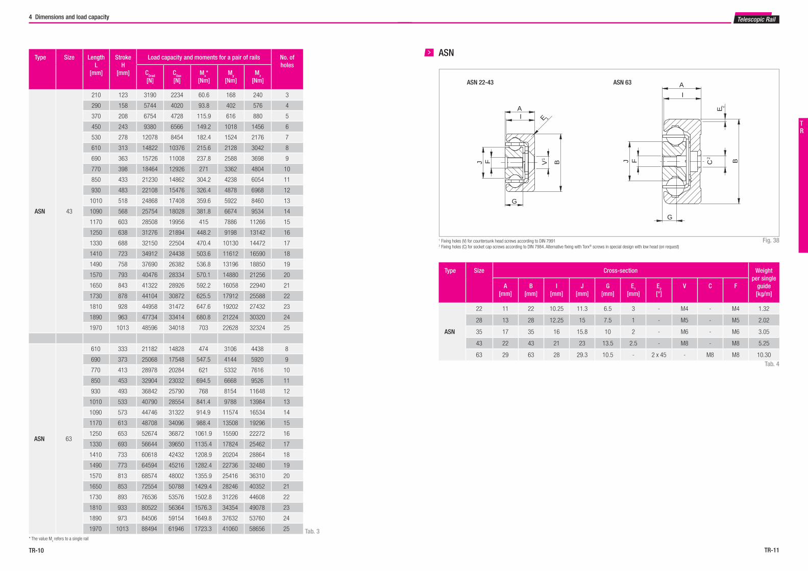
ASN 43
210 123 3190 2234 60.6 168 240 3
290 158 5744 4020 93.8 402 576 4
370 208 6754 4728 115.9 616 880 5
450 243 9380 6566 149.2 1018 1456 6
530 278 12078 8454 182.4 1524 2176 7
610 313 14822 10376 215.6 2128 3042 8
690 363 15726 11008 237.8 2588 3698 9
770 398 18464 12926 271 3362 4804 10
850 433 21230 14862 304.2 4238 6054 11
930 483 22108 15476 326.4 4878 6968 12
1010 518 24868 17408 359.6 5922 8460 13
1090 568 25754 18028 381.8 6674 9534 14
1170 603 28508 19956 415 7886 11266 15
1250 638 31276 21894 448.2 9198 13142 16
1330 688 32150 22504 470.4 10130 14472 17
1410 723 34912 24438 503.6 11612 16590 18
1490 758 37690 26382 536.8 13196 18850 19
1570 793 40476 28334 570.1 14880 21256 20
1650 843 41322 28926 592.2 16058 22940 21
1730 878 44104 30872 625.5 17912 25588 22
1810 928 44958 31472 647.6 19202 27432 23
1890 963 47734 33414 680.8 21224 30320 24
1970 1013 48596 34018 703 22628 32324 25
ASN 63
610 333 21182 14828 474 3106 4438 8
690 373 25068 17548 547.5 4144 5920 9
770 413 28978 20284 621 5332 7616 10
850 453 32904 23032 694.5 6668 9526 11
930 493 36842 25790 768 8154 11648 12
1010 533 40790 28554 841.4 9788 13984 13
1090 573 44746 31322 914.9 11574 16534 14
1170 613 48708 34096 988.4 13508 19296 15
1250 653 52674 36872 1061.9 15590 22272 16
1330 693 56644 39650 1135.4 17824 25462 17
1410 733 60618 42432 1208.9 20204 28864 18
1490 773 64594 45216 1282.4 22736 32480 19
1570 813 68574 48002 1355.9 25416 36310 20
1650 853 72554 50788 1429.4 28246 40352 21
1730 893 76536 53576 1502.8 31226 44608 22
1810 933 80522 56364 1576.3 34354 49078 23
1890 973 84506 59154 1649.8 37632 53760 24
1970 1013 88494 61946 1723.3 41060 58656 25
Type Size Cross-section Weight per single
guide[kg/m]
A[mm]
B[mm]
I[mm]
J[mm]
G[mm]
E1
[mm]E2
[°]V C F
ASN
22 11 22 10.25 11.3 6.5 3 - M4 - M4 1.32
28 13 28 12.25 15 7.5 1 - M5 - M5 2.02
35 17 35 16 15.8 10 2 - M6 - M6 3.05
43 22 43 21 23 13.5 2.5 - M8 - M8 5.25
63 29 63 28 29.3 10.5 - 2 x 45 - M8 M8 10.30
ASN 22-43 ASN 63
A
BV1
I E 1
G
J F
I
A
BC2
G
J
E 2
F
A
BV1
I E 1
G
J F
I
A
BC2
G
J
E 2
F
* The value Mx refers to a single rail
Telescopic Rail
Tab. 3
4 Dimensions and load capacity
ASN
1 Fixing holes (V) for countersunk head screws according to DIN 79912 Fixing holes (C) for socket cap screws according to DIN 7984. Alternative fixing with Torx® screws in special design with low head (on request)
Fig. 38
Tab. 4
TR

TR-13TR-12
Telescopic Rail
C0radC0rad
Fig. 39
DSS with one-sided extension (single stroke)
DSS
Type Size Length L
[mm]
StrokeH
[mm]
Load capacity for a pair of rails
C0rad
[N]
Accessi-ble holes
/ total
DSS 28
290 296 1140 3 / 4
370 380 1538 4 / 5
450 464 1938 4 / 6
530 548 2340 6 / 7
610 630 2752 6 / 8
690 714 3154 7 / 9
770 798 3556 7 / 10
850 864 4222 9 / 11
930 950 4480 9 / 12
1010 1034 4108 10 / 13
1090 1118 3792 10 / 14
1170 1202 3522 12 / 15
1250 1266 3390 12 / 16
1330 1350 3172 13 / 17
1410 1434 2980 13 / 18
1490 1518 2810 15 / 19
Type Size Length L
[mm]
StrokeH
[mm]
Load capacity for a pair of rails
C0rad
[N]
Accessi-ble holes
/ total
DSS 35
450 494 2500 5 / 6
530 558 3370 6 / 7
610 646 3816 6 / 8
690 734 4264 7 / 9
770 798 5158 8 / 10
850 886 5602 9 / 11
930 974 6048 9 / 12
1010 1038 6952 10 / 13
1090 1126 7016 11 / 14
1170 1214 6480 12 / 15
1250 1278 6242 12 / 16
1330 1366 5814 13 / 17
1410 1454 5442 14 / 18
1490 1518 5272 15 / 19
1570 1606 4964 15 / 20
1650 1694 4690 16 / 21
1730 1758 4564 17 / 22Tab. 6
Tab. 5
4 Dimensions and load capacity
Type Size Length L
[mm]
StrokeH
[mm]
Load capacity for a pair of rails
C0rad
[N]
Accessi-ble holes
/ total
DSS 43
530 556 4122 6 / 7
610 626 5206 6 / 8
690 726 5550 7 / 9
770 796 6638 7 / 10
850 866 7746 9 / 11
930 966 8072 9 / 12
1010 1036 9180 10 / 13
1090 1106 10208 10 / 14
1170 1206 9220 12 / 15
1250 1276 8796 12 / 16
1330 1376 8054 13 / 17
1410 1446 7728 14 / 18
1490 1516 7426 15 / 19
1570 1616 6890 15 / 20
1650 1686 6650 16 / 21
1730 1756 6426 17 / 22
1810 1856 6022 18 / 23
1890 1926 5838 18 / 24
1970 2026 5500 19 / 25
Tab. 7
Type Size Length L
[mm]
StrokeH
[mm]
Load capacity for a pair of rails
C0rad
[N]
Accessi-ble holes
/ total
DSS 63
610 666 7004 6 / 8
690 746 8504 8 / 9
770 826 10024 8 / 10
850 906 11560 9 / 11
930 986 13104 9 / 12
1010 1066 14658 11 / 13
1090 1146 16218 11 / 14
1170 1226 17784 12 / 15
1250 1306 19354 12 / 16
1330 1386 20928 14 / 17
1410 1466 22504 14 / 18
1490 1546 24082 15 / 19
1570 1626 25664 15 / 20
1650 1706 24728 17 / 21
1730 1786 23654 17 / 22
1810 1866 22668 18 / 23
1890 1946 21762 18 / 24
1970 2026 20926 20 / 25Tab. 8
A
B D
V1
JK
DSS
DSS with one-sided extension (single stroke)
1 Fixing holes (V) for countersunk head screws according to DIN 7991 Fig. 40
Type Size Cross-section Weight per single
guide[kg/m]
A[mm]
B[mm]
K[mm]
D[mm]
J[mm]
V
DSS
28 17 84 24.5 35 24.5 M5 6.40
35 22.5 104 30.5 43 30.5 M6 10.10
43 28 120 34 52 34 M8 14.60
63 40 208 64 80 64 M10 32.60Tab. 9
TR
Stroke H
25 80 80 80 25
Length L

TR-15TR-14
Telescopic Rail
Fig. 41
...S version with reinforced and damped stainless steel end stops
DSS...S
Type Size Length L
[mm]
StrokeH
[mm]
Load capacity for a pair of rails
C0rad
[N]
Accessible holes / total
DSS...S 43
530 556 4122 6 / 7
610 626 5206 6 / 8
690 726 5550 7 / 9
770 796 6638 7 / 10
850 866 7746 9 / 11
930 966 8072 9 / 12
1010 1036 9180 10 / 13
1090 1106 10208 10 / 14
1170 1206 9220 12 / 15
1250 1276 8796 12 / 16
1330 1376 8054 13 / 17
1410 1446 7728 14 / 18
1490 1516 7426 15 / 19
1570 1616 6890 15 / 20
1650 1686 6650 16 / 21
1730 1756 6426 17 / 22
1810 1856 6022 18 / 23
1890 1926 5838 18 / 24
1970 2026 5500 19 / 25
Tab. 10
DSS...S
...S version with reinforced and damped stainless steel end stops
1 Fixing holes (V) for countersunk head screws according to DIN 7991 Fig. 42
Type Size Cross-section Weight per single guide
[kg/m]A[mm]
B[mm]
K[mm]
D[mm]
J[mm]
V
DSS...S 43 28 120 34 52 34 M8 14.60Tab. 11
Stroke HLength L
25 25 80 80 80 80 80 80
Length L
A
B
K
D
J
V¹
Stroke HLength L
25 25 80 80 80 80 80 80
Length L
A
B
K
D
J
V¹
4 Dimensions and load capacity
C0rad0rad
TR

TR-17TR-16
Fmaxin closed position
C0radC0rad
Type Size L[mm]
Total length[mm]
C[mm]
E[mm]
Fmax*2
[N]Weight per single
guide [kg/m]
DSB
28 from 290 to 1490* L + 52 63 35 2460 6.51
35 from 450 to 1730* L + 53 78 33 3000 10.4
43 from 530 to 1970* L + 69 95 45 5630 14.98
L (left rail) R (right rail)
The DSB is built on the DSS design. The same load capacities, cross-
sections and available rail lengths apply (see pg. TR-12ff). Data in Table
10 are based on the special features of the locking mechanism.
Total length
L
C
E
Unlocking lever
A
B DV
1
JK
A
BD
V1
JK
A
B DV
1
JK
A
BD
V1
JK
DSD with double direction stroke (double stroke)
Fig. 45
Tab. 13
Type Size Length L
[mm]
StrokeH
[mm]
Load capacity for a pair of rails
C0rad
[N]
Accessi-ble holes
/ total
DSD 28
290 246 1790 4 / 4
370 326 2210 4 / 5
450 406 2634 6 / 6
530 486 3252 6 / 7
610 566 3674 8 / 8
690 646 4100 8 / 9
770 726 4524 10 / 10
850 806 4950 10 / 11
930 886 5162 12 / 12
1010 966 4714 12 / 13
1090 1046 4336 14 / 14
1170 1126 4016 14 / 15
1250 1206 3740 16 / 16
1330 1286 3498 16 / 17
1410 1366 3288 18 / 18
1490 1446 3100 18 / 19
Tab. 14
DSD
Type Size Length L
[mm]
StrokeH
[mm]
Load capacity for a pair of rails
C0rad
[N]
Accessi-ble holes
/ total
DSD 35
450 350 6050 4 / 6
530 430 6382 6 / 7
610 510 6762 6 / 8
690 590 7600 8 / 9
770 670 8016 8 / 10
850 750 8446 10 / 11
930 830 9292 10 / 12
1010 910 9736 12 / 13
1090 990 9160 12 / 14
1170 1070 8404 14 / 15
1250 1150 7764 14 / 16
1330 1230 7214 16 / 17
1410 1310 6738 16 / 18
1490 1390 6320 18 / 19
1570 1470 5950 18 / 20
1650 1550 5622 20 / 21
1730 1630 5328 20 / 22
Stroke HStroke H
25 80 80 80
Length L
Telescopic Rail4 Dimensions and load capacity
Tab. 12* For available lengths, see pg. TR-12, tab. 5 and 7 (DSS)*² When using one lock
Please observe right or left installation for version DSB.
The maximum load on the locking when closed is indicated by Fmax
.
1 Fixing holes (V) for countersunk head screws according to DIN 7991 Fig. 44
Fig. 43
B version with locking system for closed position
DSB
TR

TR-19TR-18
4 Dimensions and load capacity
A
B D
V1
JK
DSD
Type Size Length L
[mm]
StrokeH
[mm]
Load capacity for a pair of rails
C0rad
[N]
Accessi-ble holes
/ total
DSD 43
530 476 6036 6 / 7
610 556 6530 8 / 8
690 636 7562 8 / 9
770 716 8594 10 / 10
850 796 9094 10 / 11
930 876 10126 12 / 12
1010 956 11156 12 / 13
1090 1036 11660 14 / 14
1170 1116 10784 14 / 15
1250 1196 10028 16 / 16
1330 1276 9372 16 / 17
1410 1356 8796 18 / 18
1490 1436 8286 18 / 19
1570 1516 7834 20 / 20
1650 1596 7426 20 / 21
1730 1676 7060 22 / 22
1810 1756 6728 22 / 23
1890 1836 6426 24 / 24
1970 1916 6150 24 / 25 Tab. 16
Type Size Length L
[mm]
StrokeH
[mm]
Load capacity for a pair of rails
C0rad
[N]
Accessi-ble holes
/ total
DSD 63
610 398 23716 6 / 8
690 478 24484 6 / 9
770 558 25434 8 / 10
850 638 26500 8 / 11
930 718 27646 10 / 12
1010 798 28848 10 / 13
1090 878 30092 12 / 14
1170 958 31368 12 / 15
1250 1038 32668 14 / 16
1330 1118 33988 14 / 17
1410 1198 35322 16 / 18
1490 1278 36670 16 / 19
1570 1358 38018 18 / 20
1650 1438 35538 18 / 21
1730 1518 33360 20 / 22
1810 1598 31436 20 / 23
1890 1678 29720 22 / 24
1970 1758 28182 22 / 25
Tab. 15
Type Size Cross-section Weight per single
guide[kg/m]
A[mm]
B[mm]
K[mm]
D[mm]
J[mm]
V
DSD
28 17 84 24.5 35 24.5 M5 6.40
35 22.5 104 30.5 43 30.5 M6 10.10
43 28 120 34 52 34 M8 14.60
63 40 208 64 80 64 M10 32.60
Tab. 17
Fig. 461 Fixing holes (V) for countersunk head screws according to DIN 7991
DSD with double direction stroke (double stroke)
C0radC0rad
Telescopic Rail
E version with extra stroke
Fig. 47
Tab. 18
Type Size Length L
[mm]
StrokeH
[mm]
Load capacity for a pair of rails
C0rad
[N]
No. of holesfi xed part
No. of holes
mobile part
DSE 28
290 444 702 3 / 4 4
370 570 952 4 / 5 5
450 696 1200 4 / 6 6
530 822 1450 6 / 7 7
610 946 1702 6 / 8 8
690 1072 1684 7 / 9 9
770 1198 1506 7 / 10 10
850 1297 1420 9 / 11 11
930 1425 1292 9 / 12 12
1010 1551 1184 10 / 13 13
1090 1677 1094 10 / 14 14
1170 1803 1016 12 / 15 15
Type Size Length L
[mm]
StrokeH
[mm]
Load capacity for a pair of rails
C0rad
[N]
No. of holesfi xed part
No. of holes
mobile part
DSE 35
450 741 1552 5 / 6 6
530 837 2098 6 / 7 7
610 969 2376 6 / 8 8
690 1101 2652 7 / 9 9
770 1197 3182 8 / 10 10
850 1329 2850 9 / 11 11
930 1461 2582 9 / 12 12
1010 1557 2466 10 / 13 13
1090 1689 2262 11 / 14 14
1170 1821 2090 12 / 15 15
1250 1917 2012 12 / 16 16
1330 2049 1874 13 / 17 17
1410 2181 1754 14 / 18 18
1490 2277 1700 15 / 19 19
DSE
Tab. 19
Length L
L
Stroke H
25 2580 80 80 80 80 80
25 2580 80 80 80 80 80
TR

TR-21TR-20
Fig. 49
DSC
Tab. 23
Type Size Length L
[mm]
StrokeH
[mm]
Load capacity for a pair of rails Fixed element Movable element
C0rad
[N]C0ax
[N]Accessible holes
/ totalLength [mm]
Accessible holes / total
Length [mm]
DSC 43
530 552 4780 3346 5 / 5 402 6 / 7 530
610 619 5928 4150 6 / 6 465 6 / 8 610
690 725 6190 3840 6 / 6 520 8 / 9 690
770 792 7332 3584 7 / 7 582 8 / 10 770
850 859 8492 3362 8 / 8 644 9 / 11 850
930 965 8738 2918 9 / 9 700 9 / 12 930
1010 1029 10508 2784 10 / 10 770 11 / 13 1010
1090 1099 11058 2634 10 / 10 825 11 / 14 1090
1170 1202 10354 2364 11 / 11 887 12 / 15 1170
1250 1272 9874 2254 12 / 12 942 12 / 16 1250
1330 1375 8998 2054 13 / 13 1005 14 / 17 1330
1410 1445 8634 1972 14 / 14 1060 14 / 18 1410
1490 1509 8362 1910 14 / 14 1130 15 / 19 1490
1570 1615 7698 1758 15 / 15 1185 16 / 20 1570
1650 1685 7428 1696 15 / 15 1240 16 / 21 1650
1730 1752 7202 1644 16 / 16 1302 17 / 22 1730
1810 1843 6812 1556 17 / 17 1365 18 / 23 1810
1890 1922 6540 1494 18 / 18 1427 19 / 24 1890
1970 2028 6126 1390 19 / 19 1482 20 / 25 1970
Telescopic Rail
Type Size Length L
[mm]
StrokeH
[mm]
Load capacity for a pair of rails
C0rad
[N]
No. of holesfi xed part
No. of holes
mobile part
DSE 43
530 834 2582 6 / 7 7
610 939 3264 6 / 8 8
690 1089 3470 7 / 9 9
770 1194 4154 7 / 10 10
850 1299 4852 9 / 11 11
930 1449 5012 9 / 12 12
1010 1554 4728 10 / 13 13
1090 1659 4476 11 / 14 14
1170 1809 4044 12 / 15 15
1250 1914 3856 12 / 16 16
1330 2064 3532 13 / 17 17
1410 2169 3388 13 / 18 18
1490 2274 3256 15 / 19 19
1570 2409 3078 15 / 20 20
1650 2529 2916 16 / 21 21
1730 2634 2818 16 / 22 22
1810 2784 2640 18 / 23 23
1890 2889 2560 18 / 24 24
1970 3039 2412 19 / 25 25 Tab. 21
Type Size Length L
[mm]
StrokeH
[mm]
Load capacity for a pair of rails
C0rad
[N]
No. of holesfi xed part
No. of holes
mobile part
DSE 63
610 999 4328 6 / 8 8
690 1119 5260 8 / 9 9
770 1239 6208 8 / 10 10
850 1359 7164 9 / 11 11
930 1479 8128 9 / 12 12
1010 1599 9096 11 / 13 13
1090 1719 10070 11 / 14 14
1170 1839 11046 12 / 15 15
1250 1959 11344 12 / 16 16
1330 2079 10714 14 / 17 17
1410 2199 10152 14 / 18 18
1490 2319 9644 15 / 19 19
1570 2439 9186 15 / 20 20
1650 2559 8768 17 / 21 21
1730 2679 8388 17 / 22 22
1810 2799 8038 18 / 23 23
1890 2919 7718 18 / 24 24
1970 3039 7420 20 / 25 25
Tab. 20
4 Dimensions and load capacity
DSE
Type Size Cross-section Weight per single
guide[kg/m]
A[mm]
B[mm]
K[mm]
D[mm]
J[mm]
F V1
DSE
28 30 84 24.5 35 24.5 M5 M5 8.4
35 39.5 104 30.5 43 30.5 M6 M6 13.2
43 50 120 34 52 34 M8 M8 19.9
63 69 208 64 80 64 M8 M10 42.9
Tab. 22
Fig. 481 Fixing holes (V) for countersunk head screws according to DIN 7991 Please observe right or left installation for version DSE.
E version with extra stroke
A
B
JD
K
F
V1
A
B
JD
K
F
V1
L (left rail) R (right rail)
TR
C0rad0rad
C0ax
Lenght fixed element Stroke H
25 80 80 80 80 80 80
Lenght movable element
25 80 80 80 80
Length L

TR-23TR-22
C0ax
C0radC
4 Dimensions and load capacity
A
B
J
V¹
F
Fig. 50
DSC
Type Size Cross-section Weight per single
guide[kg/m]
A[mm]
B[mm]
J[mm]
F[mm]
V1
[mm]
DSC 43 43 100 50 M8 M6 13.4Tab. 24
1 Fixing holes (V) for countersunk head screws according to DIN 7991
Type Size Length L
[mm]
StrokeH
[mm]
Load capacity for a pair of rails No. ofholes
C0rad
[N]C0ax
[N]
DEFDEVDEM
22
130 152 238 166 2
210 222 562 392 3
290 308 780 546 4
370 392 1002 526 5
450 462 1348 460 6
530 548 1142 386 7
610 632 988 334 8
690 702 906 306 9
770 788 802 270 10
Type Size Length L
[mm]
StrokeH
[mm]
Load capacity for a pair of rails No. ofholes
C0rad
[N]C0ax
[N]
DEFDEVDEM
28
130 148 470 328 2
210 232 864 604 3
290 296 1534 1074 4
370 380 1936 942 5
450 464 2338 770 6
530 548 2214 650 7
610 633 1910 560 8
690 717 1684 494 9
770 801 1506 442 10
850 866 1420 416 11
930 950 1292 378 12
1010 1034 1184 348 13
1090 1118 1094 320 14
1170 1202 1016 298 15
Telescopic Rail
DE
* Remove the set screw to reach all the fi xing holes. See also assembly instructions on page TR-47f. Fig. 51
Tab. 25
Tab. 26
TR
Length L Stroke H
25 80 80 25

TR-25TR-24
4 Dimensions and load capacity
Type Size Length L
[mm]
StrokeH
[mm]
Load capacity for a pair of rails No. ofholes
C0rad
[N]C0ax
[N]
DEFDEVDEM
35
210 254 804 562 3
290 318 1600 1120 4
370 406 2050 1436 5
450 494 2500 1586 6
530 558 3370 1456 7
610 646 3816 1252 8
690 734 3378 1096 9
770 798 3182 1032 10
850 886 2850 926 11
930 974 2582 838 12
1010 1038 2466 800 13
1090 1126 2262 734 14
1170 1214 2090 678 15
1250 1278 2012 654 16
1330 1366 1874 608 17
1410 1454 1754 570 18
1490 1518 1700 552 19
Type Size Length L
[mm]
StrokeH
[mm]
Load capacity for a pair of rails No. ofholes
C0rad
[N]C0ax
[N]
DEFDEVDEM
43
210 246 1210 848 3
290 316 2228 1560 4
370 416 2600 1820 5
450 486 3656 2558 6
530 556 4750 2868 7
610 626 5868 2600 8
690 726 6182 2192 9
770 796 6110 2032 10
850 866 5694 1892 11
930 966 5012 1666 12
1010 1036 4728 1572 13
1090 1106 4476 1488 14
1170 1206 4044 1344 15
1250 1276 3856 1282 16
1330 1376 3532 1174 17
1410 1446 3388 1126 18
1490 1516 3256 1082 19
1570 1586 3134 1042 20
1650 1686 2916 970 21
1730 1756 2818 936 22
1810 1856 2640 878 23
1890 1926 2560 850 24
1970 2026 2412 802 25
Type Size Length L
[mm]
StrokeH
[mm]
Load capacity for a pair of rails No. ofholes
C0rad
[N]C0ax
[N]
DEF 63
610 666 8180 5726 8
690 746 9718 6124 9
770 826 11270 5568 10
850 906 12830 5106 11
930 986 14396 4714 12
1010 1066 13770 4378 13
1090 1146 12854 4086 14
1170 1226 12052 3832 15
1250 1306 11344 3606 16
1330 1386 10714 3406 17
1410 1466 10152 3228 18
1490 1546 9644 3066 19
1570 1626 9186 2920 20
1650 1706 8768 2788 21
1730 1786 8388 2666 22
1810 1866 8038 2556 23
1890 1946 7718 2454 24
1970 2026 7420 2360 25
Telescopic Rail
Tab. 29
Tab. 28
Tab. 27
Type Size Cross-section Weight per single
guide[kg/m]
A[mm]
B[mm]
G[mm]
F V
DEFDEVDEM
22 22 22 6.5 M4 M4 2.64
28 26 28 7.5 M5 M5 4.04
35 34 35 10 M6 M6 6.10
43 44 43 13.5 M8 M8 10.50
63 58 63 10.5 M8 - 20.60
DE 22-43 DEF 63
A
B
V1
G
F
A
B
G
F
DE(-F, -V, -M)22-43 DEF63
A
B
V1
G
F
A
B
G
F
DE(-F, -V, -M)22-43 DEF63
DE
1 Fixing holes (V) for countersunk head screws according to DIN 7991 Fig. 52
Tab. 30
There are three options for mounting holes available for
the DE series in sizes 22 to 43:
Version DEF with threaded holes,
Version DEV with counter-sunk holes,
Version DEM, both variants (mixed) (see fig. 52).
Size 63 is only available with threaded holes.
TR

TR-27TR-26
4 Dimensions and load capacity Telescopic Rail
C0ax
C0radC
Type Size Length L
[mm]
StrokeH
[mm]
Load capacity for a pair of rails
Slider[mm]
B[mm]
No ofholes
C0rad
[N]C0ax
[N]
DE...S 28
290 300 704 494 264 49 3
370 384 1084 758 344 49 4
450 468 1470 756 424 49 5
530 533 2100 686 504 49 6
610 636 1892 556 584 49 7
690 701 1760 516 664 49 8
770 804 1494 438 744 49 9
850 850 1474 432 824 49 10
930 953 1284 376 904 49 11
1010 1018 1222 358 984 49 12
1090 1102 1124 330 1064 49 13
1170 1186 1042 306 1144 49 14
Type Size Length L
[mm]
StrokeH
[mm]
Load capacity for a pair of rails
Slider[mm]
B[mm]
No ofholes
C0rad
[N]C0ax
[N]
DE...S 35
370 370 1430 1000 338 45 4
450 464 1788 1252 418 45 5
530 536 2476 1574 498 45 6
610 630 2832 1312 578 45 7
690 702 3540 1194 658 45 8
770 796 3198 1038 738 45 9
850 868 2966 962 818 45 10
930 962 2644 858 898 45 11
1010 1012 2592 842 978 45 12
1090 1128 2254 732 1058 45 13
1170 1178 2216 720 1138 45 14
1250 1272 2030 660 1218 45 15
1330 1344 1936 628 1298 45 16
1410 1438 1792 582 1378 45 17
1490 1510 1718 558 1458 45 18
Tab. 31
Tab. 32
DE...S
Fig. 53
...S version with reinforced and damped stainless steel end stops
Length L
65 80 65 80
A B
G
F
V¹
(49)
Stroke H
55 through-hole for fixing screw*
Type Size Cross-section Weight per single
guide[kg/m]
A[mm]
B[mm]
G[mm]
F V
DE...S
28 26 28 7.5 M5 M5 4.04
35 34 35 10 M6 M6 6.10
43 44 43 13.5 M8 M8 10.50
Type Size Length L[mm]
StrokeH
[mm]
Load capacity for a pair of rails Slider[mm]
B[mm]
No ofholes
C0rad
[N]C0ax
[N]
DE...S 43
370 366 2014 1410 338 45 4
450 496 1864 1306 418 45 5
530 536 3418 2394 498 45 6
610 636 3796 2522 578 45 7
690 706 4838 2312 658 45 8
770 806 5206 1982 738 45 9
850 846 5964 1982 818 45 10
930 976 4914 1634 898 45 11
1010 1016 4914 1634 978 45 12
1090 1116 4398 1462 1058 45 13
1170 1186 4178 1390 1138 45 14
1250 1286 3798 1262 1218 45 15
1330 1326 3798 1262 1298 45 16
1410 1456 3344 1112 1378 45 17
1490 1496 3344 1112 1458 45 18
1570 1596 3096 1030 1538 45 19
1650 1666 2986 992 1618 45 20
1730 1766 2786 926 1698 45 21
1810 1806 2786 926 1778 45 22
1890 1936 2534 842 1858 45 23
1970 2066 2322 772 1938 45 24
Length L
65 80 65 80
A
B
G
F
V¹
(49)
Stroke H
55 through-hole for fixing screw*
Tab. 33
DE...S
Fig. 54
Tab. 34
1 Fixing holes (V) for countersunk head screws according to DIN 7991
...S version with reinforced and damped stainless steel end stops
TR
TR-29TR-28
4 Dimensions and load capacity
Fig. 57
DED version D
65 65
A
A
C
C
F
V1
A
B
HubLäuferlänge
L (schienenlänge)
N° Abstände x 80
B
1 Fixing holes (V) for countersunk head screws according to DIN 7991
DED with double direction stroke (double stroke)
Type Size LengthL
[mm]
StrokeH
[mm]
Load capacity for a pair of rails
Slider[mm]
C[mm]
No. ofholes
C0rad
[N]C0ax
[N]
DED...DDEV...DDEN...D
43
290 301 1002 702 240 40 3
370 401 1400 980 320 40 4
450 471 2318 1622 400 40 5
530 541 3312 2318 480 40 6
610 641 3696 2484 560 40 7
690 711 4724 2280 640 40 8
770 781 5784 2108 720 40 9
850 881 5506 1830 800 40 10
930 951 5166 1718 880 40 11
1010 1021 4866 1618 960 40 12
1090 1121 4360 1450 1040 40 13
1170 1191 4144 1378 1120 40 14
1250 1261 3948 1312 1200 40 15
1330 1361 3608 1200 1280 40 16
1410 1431 3458 1150 1360 40 17
1490 1501 3322 1104 1440 40 18
1570 1601 3076 1024 1520 40 19
1650 1671 2968 986 1600 40 20
1730 1741 2866 952 1680 40 21
1810 1841 2682 892 1760 40 22
1890 1911 2600 864 1840 40 23
1970 2011 2448 814 1920 40 24
Tab. 37
Type Size LengthL
[mm]
StrokeH
[mm]
Load capacity for a pair of rails
Slider[mm]
C[mm]
No. ofholes
C0rad
[N]C0ax
[N]
DEF...D 63
610 602 7688 5382 558 39 7
690 682 9236 6466 638 39 8
770 762 10796 6514 718 39 9
850 842 12362 5890 798 39 10
930 922 13934 5374 878 39 11
1010 1002 15512 4942 958 39 12
1090 1082 14386 4574 1038 39 13
1170 1162 13388 4256 1118 39 14
1250 1242 12520 3980 1198 39 15
1330 1322 11758 3738 1278 39 16
1410 1402 11084 3524 1358 39 17
1490 1482 10482 3332 1438 39 18
1570 1562 9942 3160 1518 39 19
1650 1642 9456 3006 1598 39 20
1730 1722 9014 2866 1678 39 21
1810 1802 8612 2738 1758 39 22
1890 1882 8244 2620 1838 39 23
1970 1962 7906 2514 1918 39 24
Tab. 38
Type Size Cross-section Weight per single
guide[kg/m]
A[mm]
B[mm]
F V1
DE...D
28 26 28 M5 M5 4.04
35 34 35 M6 M6 6.10
43 44 43 M8 M8 10.50
63 58 63 M8 - 20.60
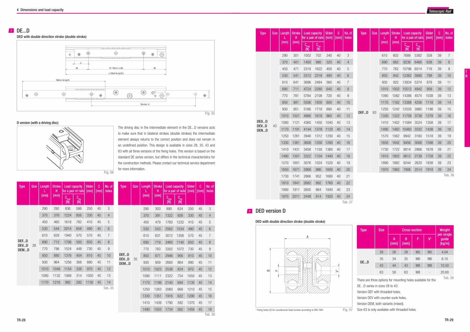
Tab. 39There are three options for mounting holes available for the
DE...D series in sizes 28 to 43:
Version DEF with threaded holes,
Version DEV with counter-sunk holes,
Version DEM, both variants (mixed).
Size 63 is only available with threaded holes.
Telescopic Rail
DED with double direction stroke (double stroke)DE...D
Fig. 55
65 65
C
F
V1
A
B
Stroke H
Slider length
L (Rail length)
N° Pitch x 80
Tab. 35
Type Size LengthL
[mm]
StrokeH
[mm]
Load capacity for a pair of rails
Slider[mm]
C[mm]
No. ofholes
C0rad
[N]C0ax
[N]
DEF...D DEV...D DEM...D
35
290 303 890 624 250 45 3
370 391 1322 926 330 45 4
450 479 1760 1232 410 45 5
530 543 2562 1534 490 45 6
610 631 3012 1308 570 45 7
690 719 3460 1140 650 45 8
770 783 3302 1072 730 45 9
850 871 2946 956 810 45 10
930 959 2660 864 890 45 11
1010 1023 2536 824 970 45 12
1090 1111 2322 754 1050 45 13
1170 1199 2140 694 1130 45 14
1250 1263 2060 668 1210 45 15
1330 1351 1916 622 1290 45 16
1410 1439 1790 582 1370 45 17
1490 1503 1734 562 1450 45 18
Type Size LengthL
[mm]
StrokeH
[mm]
Load capacity for a pair of rails
Slider[mm]
C[mm]
No. ofholes
C0rad
[N]C0ax
[N]
DEF...D DEV...D DEM...D
28
290 292 836 586 250 45 3
370 376 1224 856 330 45 4
450 460 1618 782 410 45 5
530 544 2014 658 490 45 6
610 628 1940 570 570 45 7
690 712 1706 500 650 45 8
770 796 1524 448 730 45 9
850 880 1376 404 810 45 10
930 964 1256 368 890 45 11
1010 1048 1154 338 970 45 12
1090 1132 1068 314 1050 45 13
1170 1216 992 292 1130 45 14
Tab. 36
D version (with a driving disc)
Fig. 56
The driving disc in the intermediate element in the DE...D versions acts
to make sure that in bilateral strokes (double strokes) the intermediate
element always returns to the correct position and does not remain in
an undefined position. This design is available in sizes 28, 35, 43 and
63 with all three versions of the fixing holes. This version is based on the
standard DE series version, but differs in the technical characteristics for
the construction methods. Please contact our technical service department
for more information.
TR

TR-31TR-30
Type1 Size Length L[mm]
StrokeH
[mm]
Load capacity fora pair of rails
No. ofholes
C0rad
[N]C0ax
[N]
DEF...Z 43
290 243 1746 1222 4
370 323 1947 1363 5
450 403 2481 1737 6
530 483 3016 1915 7
610 563 3229 1618 8
690 643 3762 1401 9
770 723 3714 1235 10
850 803 3321 1104 11
930 883 3004 999 12
1010 963 2741 911 13
1090 1043 2521 838 14
1170 1123 2334 776 15
1250 1203 2172 722 16
1330 1283 2032 675 17
1410 1363 1908 634 18
1490 1443 1799 598 19
1570 1523 1701 566 20
1650 1603 1614 537 21
1730 1683 1535 510 22
1810 1763 1463 486 23
1890 1843 1398 465 24
1970 1923 1338 445 25
4 Dimensions and load capacity
Length L Stroke H
25 80 80 25
C0radC0rad
C0ax
Fig. 59
DE...Z
1 Fixing holes (V) for countersunk head screws according to DIN 7991
DE...Z with double direction stroke (double stroke)
Type Size Cross-section Weight per single
guide[kg/m]
A[mm]
B[mm]
F
DEF...Z 43 44 43 M8 10.50Tab. 41
B
A
F
Telescopic Rail
Tab. 40
Fig. 58
1 The synchronized full extension is only available in version F with threaded mounting holes
DE...ZVersion Z with synchronized full extension
TR

TR-33TR-32
C0ax
Set screw*
C0radC
Type Size Length L
[mm]
StrokeH
[mm]
Load capacity for a pair of rails
No. ofholes
C0rad
[N]C0ax
[N]
DBN 35
210 254 804 562 3
290 318 1334 1120 4
370 406 1044 1044 5
450 494 858 858 6
530 558 788 788 7
610 646 676 676 8
690 734 594 594 9
770 798 558 558 10
850 886 500 500 11
930 974 454 454 12
1010 1038 434 434 13
1090 1126 398 398 14
1170 1214 366 366 15
1250 1278 354 354 16
1330 1366 330 330 17
1410 1454 308 308 18
1490 1518 298 298 19
Type Size Length L
[mm]
StrokeH
[mm]
Load capacity for a pair of rails
No. ofholes
C0rad
[N]C0ax
[N]
DBN 43
210 246 1210 848 3
290 316 2228 1560 4
370 416 2600 1820 5
450 486 2662 2558 6
530 556 2386 2386 7
610 626 2164 2164 8
690 726 1824 1824 9
770 796 1690 1690 10
850 866 1576 1576 11
930 966 1386 1386 12
1010 1036 1308 1308 13
1090 1106 1238 1238 14
1170 1206 1118 1118 15
1250 1276 1066 1066 16
1330 1376 976 976 17
1410 1446 938 938 18
1490 1516 900 900 19
1570 1586 868 868 20
1650 1686 806 806 21
1730 1756 780 780 22
1810 1856 730 730 23
1890 1926 708 708 24
1970 2026 668 668 25
4 Dimensions and load capacity
Type Size Cross-section Weight per single
guide[kg/m]
A[mm]
B[mm]
E[mm]
V
DBN
22 22 22 3 M4 2.64
28 26 28 1 M5 4.04
35 34 35 2 M6 6.10
43 44 43 2.5 M8 10.50
A
B
V1
E
Type Size Length L
[mm]
StrokeH
[mm]
Load capacity for a pair of rails
No. ofholes
C0rad
[N]C0ax
[N]
DBN 22
130 152 238 166 2
210 222 562 392 3
290 308 472 472 4
370 392 372 372 5
450 462 324 324 6
530 548 272 272 7
610 632 234 234 8
690 702 216 216 9
770 788 190 190 10
Type Size Length L
[mm]
StrokeH
[mm]
Load capacity for a pair of rails
No. ofholes
C0rad
[N]C0ax
[N]
DBN 28
130 148 470 328 2
210 232 864 604 3
290 296 1244 1074 4
370 380 964 964 5
450 464 786 786 6
530 548 664 664 7
610 633 572 572 8
690 717 504 504 9
770 801 452 452 10
850 866 426 426 11
930 950 388 388 12
1010 1034 356 356 13
1090 1118 328 328 14
1170 1202 304 304 15Tab. 43
Tab. 42
Fig. 60* Remove the set screw to reach all the fi xing holes. See also assembly instructions on page TR-47f.
DBN
Length LStroke H Stroke H
25 80 80 25
Telescopic Rail
Tab. 44
Tab. 45
Tab. 46
1 Fixing holes (V) for countersunk head screws according to DIN 7991 Fig. 61
DBN
TR

TR-35TR-34
Type Size Length L
[mm]
Stroke H
[mm]
Load capacityfor a pair of rails
C0rad
[N]
Fixed element
Accessible holes / total
Movable element
Accessible holes / total
DMS 63
1010 1051 16104 10 / 13 10 / 13
1090 1141 17496 10 / 14 11 / 14
1170 1216 19168 11 / 15 11 / 15
1250 1291 20848 12 / 16 13 / 16
1330 1381 22238 13 / 17 13 / 17
1410 1456 23920 13 / 18 14 / 18
1490 1531 25608 14 / 19 14 / 19
1570 1621 26996 14 / 20 15 / 20
1650 1696 28686 16 / 21 16 / 21
1730 1771 30380 16 / 22 17 / 22
1810 1861 31766 17 / 23 17 / 23
1890 1936 33460 18 / 24 19 / 24
1970 2026 34846 19 / 25 19 / 25
2050 2101 36542 19 / 26 20 / 26
2130 2176 38240 20 / 27 20 / 27
2210 2266 39624 21 / 28 22 / 28
4 Dimensions and load capacity
Type Size Cross-section Weight per single
guide[kg/m]
A[mm]
B[mm]
I[mm]
K[mm]
D[mm]
J[mm]
C V
DMS 63 63 200 50 58.5 60 81.5 M8 M8 43
I
A
B
JD
K
V1
C2
I
B
A
JD
K
C2
V1
I
A
B
JD
K
V1
C2
I
B
A
JD
K
C2
V1
Telescopic Rail
C0radC0rad
DMS
Fig. 62
Tab. 47
Tab. 48
1 Fixing holes (V) for countersunk head screws according to DIN 79912 Fixing holes (C) for socket cap screws according to DIN 7984. Alternative fi xing with Torx® screws in special design with low head (on request) Please observe right or left installation for version DMS.
Fig. 63
DMS
Fixed element
Size 63
L (left rail) R (right rail)
Fixed element
Size 63
Movable element
Size 43
TR
Length L Stroke H
25 80 80 80 80 80 80 80 80 80 80 80 80 25

TR-37TR-36
C0rad
Type Size LengthL
[mm]
StrokeH
[mm]
Load capacityfor a pair of rails
C0rad
[N]
Accessible holes / total
DRT 43
770 780 4770 10 / 10
850 860 4920 10 / 11
930 940 5040 12 / 12
1010 1020 5150 12 / 13
1090 1100 5240 14 / 14
1170 1180 5320 14 / 15
1250 1260 5380 16 / 16
1330 1340 5440 16 / 17
1410 1420 5490 18 / 18
1490 1500 5540 18 / 19
1570 1580 5580 20 / 20
1650 1660 5610 20 / 21
1730 1740 5650 22 / 22
1810 1820 5680 22 / 23
1890 1900 5700 24 / 24
1970 1980 5720 24 / 25
4 Dimensions and load capacity
Type Size Cross-section Weight per single
guide[kg/m]
A[mm]
B[mm]
K[mm]
D[mm]
J[mm]
C
DRT28 17 84 24.5 35 24.5 M5* 5.0
43 29 120 34 52 34 M8 11.20
A
JD
K
B
C3
A
B
JD
K
C3
A
JD
K
B
C3
A
B
JD
K
C3
Telescopic Rail
DRT
Fig. 64
Tab. 50
Tab. 49
Tab. 51
Fig. 65
R (right rail)
3 For DRT43 fi xing holes for Torx® screws in custom design with load head (included in scope of supply), DRT28 has contersunk holes. Please observe right or left installation for version DRT.
* Contersunk screw.
L (left rail)
DRT
Type Size LengthL
[mm]
StrokeH
[mm]
Load capacityfor a pair of rails
C0rad
[N]
Accessible holes / total
DRT 28
450 464 705 6 / 6
530 548 755 7 / 7
610 630 795 8 / 8
690 714 821 9 / 9
770 798 842 10 / 10
850 864 892 11 / 11
930 950 899 12 / 12
1010 1034 907 13 / 13
1090 1118 915 14 / 14
1170 1202 922 15 / 15
TR
Length L Stroke H
25 80 80 80 80 80 80 80 80 80 25

TR-39TR-38
P1 = C
0rad
Static load check
5 Technical instructions
f = ––– · P (mm)q
t
q
Technical instructions
f P
Telescopic Rail
Telescopic rail selectionSelecting the suitable telescopic rail should be done based on the load
and the maximum permissible deflection in the extended state. The load
capacity of a telescopic rail depends on two factors: the loading capacity
of the ballcage and the rigidity of the intermediate element. For mainly
short strokes the load capacity is determined by the load-bearing capacity
of the ballcage; for average and long strokes it is determined by the rigidi-
ty of the intermediate element. Therefore series, which otherwise contain
comparable components, are also suited for differing load capacities.
The values in the load capacity tables of the corresponding series (see
Sect. 4, Product Dimensions, pg. TR-8ff) give the maximum permissible
loading of a pair of rails in the middle of the two rails and in the center
line of the moving element with the rails in the completely extended state.
Using a pair of rails, the loading acts in the centre on both rails (see fig.
67, P1).
The load capacity of a rail pair is:
Fig. 67Fig. 66
DeflectionIf the load P acts vertically on the pair of rails (see fig. 68), the expected
elastic deflection in the extended state can be determined as follows:
Fig. 68
Fig. 70
Whereby:
f is the expected elastic deflection in mm
q is a stroke coefficient (see fig. 71)
t is a factor depending on the model of the telescopic rail (see fig. 69)
P is the actual load acting on the centre of a pair of rails, in N
Also refer to page TR-40 for checking the static load
Fig. 71
Stroke in mm
DS28 t = 360
DS35 t = 940
DS43 t = 1600
DS63 t = 8000
DE22 t = 16
DE28 t = 34
DE35 t = 108
DE43 t = 240
DE63 t = 1080
DBN22 t = 6
DBN28 t = 16
DBN35 t = 26
DBN43 t = 112
DMS63 t = 7000
DRT28 t = 360
DRT43 t = 1600
DSC43 t = 1600
Fig. 69
This estimated value assumes an absolutely rigid adjacent construction.
If this rigidity is not present, the actual deflection will deviate from the
calculation.
Important:
With the partial extensions of the ASN series, the deflection is almost
completely determined by the rigidity, i.e. by the moment of inertia of the
adjacent construction.
For guides Series DSE please contact Rollon technical support.
TR

TR-41TR-40
P0rad
1
C0rad
S0
≤P
0ax 1
C0ax
S0
≤M
1 1
Mx S
0
≤M
2 1
My S
0
≤M
3 1
Mz S
0
≤
5 Technical instructions
ASN, DS, DE, DBN, DRT, DSC
Neither shocks nor vibrations, smooth and low-frequency direction change,
clean environment1.3 - 1.8
Light vibrations and average direction change 1.8 - 2.3
Shocks and vibrations, high-frequency direction change, very dirty environment 2.3 - 3.5
Telescopic Rail
Fig. 73
The above formulas are valid for a single load case. If two or more of the
described forces act simultaneously, the following check must be made:
Fig. 72
The ratio of the actual load to maximum permissible load may be as large
as the reciprocal of the accepted safety factor, S0, at the most.
Neither shocks nor vibrations, smooth and low-frequency reverse,
high assembly accuracy, no elastic deformations1.5
Normal installation conditions 1.5 - 2
Shocks and vibrations, high-frequency reverse, significant elastic deformation 2 - 3.5
Tab. 52
Safety factor S0
and the mechanical strength. A safety factor, S0, is used to check the static
load, which takes into account the basic parameters of the application and
is defined in more detail in the following table:
Static loadThe telescopic extension of the various series allow different forces and
moments (see Sect. 4, Product dimensions, pg. TR-8ff).
During the static tests the radial load capacity, C0rad
, the axial load capa-
city, C0ax
, and moments Mx, M
y and M
z indicate the maximum permissible
values of the loads; higher loads negatively effect the running properties
Lkm
= 100 · ( ––– · ––– )3δ
W
1
fi
Lkm
= calculated service life in km
δ = load capacity factor in N
W = equivalent load in N for a pair of rails
fi = application coefficient
Fig. 75
If the external load, P, is the same as the dynamic load capacity, C0rad
,
(which of course must never be exceeded), the service life at ideal opera-
ting conditions (fi = 1) amounts to 100 km.
Naturally, for a single load P, the following applies: W = P. If several external
loads occur simultaneously, the equivalent load is calculated as follows:
Tab. 53
Application coefficient fi
Fig. 74
The service life is defined as the time span between commissioning and
the first sign of fatigue or wear indications on the raceways. The service
life of a telescopic rail is dependent on several factors, such as the effec-
tive load, the installation precision, occurring shocks and vibrations, the
operating temperature, the ambient conditions and the lubrication. Calcu-
lation of the service life is based exclusively on the loaded rows of balls.
In practice, the decommissioning of the bearing, due to its destruction or
extreme wear of a component, represents the end of service life.
This is taken into account by an application coefficient (fi in the formula
below), so the service life consists of:
Service life
P0rad
P0ax
M1 M
2 M
3
C0rad
C0ax
Mx M
y M
z
+ + + + ≤1
S0
P0rad
= effective radial load
C0rad
= permissible radial load
P0ax
= effective axial load
C0ax
= permissible axial load
M1 = effective moment in the x-direction
Mx = permissible moment in the x-direction
M2 = effective moment in the y-direction
My = permissible moment in the y-direction
M3 = effective moment in the z-direction
Mz = permissible moment in the z-direction
W = Prad
+ ( ––– + ––– + ––– + –––) · C0rad
Pax
C0ax
M1
Mx
M2
My
M3
Mz
TR

TR-43TR-42
5 Technical instructions Telescopic Rail
Load capacity factor δ
Length[mm]
ASN
22 28 35 43 63
δ[N]
130 830 1744
210 1864 3154 3066 4576
290 2590 5384 5812 8110
370 3330 6810 7442 9588
450 4410 8238 9074 13204
530 5134 9664 11980 16902
610 5872 11114 13606 20650 30006
690 6960 12542 15234 22010 35416
770 7684 13968 18186 25754 40854
850 16222 19806 29524 46310
930 17622 21428 30858 51778
1010 19048 24402 34620 57258
1090 20474 26018 35962 62748
1170 21900 27636 39720 68242
1250 30622 43494 73742
1330 32236 44822 79246
1410 33850 48590 84754
1490 36846 52372 90266
1570 56166 95780
1650 57466 101296
1730 61252 106814
1810 62562 112332
1890 66344 117854
1970 67658 123376
Length[mm]
DS... DSE DSC
28 35 43 63 28 35 43 63 43
δ[N]
290 1726 1084
370 2328 1466
450 2932 3784 1848 2390
530 3536 5080 6240 2232 3224 3976 7194
610 4156 5756 7858 10656 2620 3650 5018 6690 8902
690 4762 6434 8394 12918 3004 4080 4792 8126 9322
770 5368 7762 10020 15208 3388 4934 6388 9578 11022
850 6360 8436 11672 17518 4028 5358 7452 11046 12746
930 6948 9110 12180 19842 4406 5784 7758 12526 13144
1010 7556 10452 13832 22178 4792 6650 8820 14012 15760
1090 8162 11122 15500 24522 5412 7072 9896 15504 16592
1170 8768 11794 15292 26874 5562 7496 10190 17002 17868
1250 9792 13146 17658 29232 8368 11264 18504 18702
1330 10386 13814 18154 31596 8790 11562 20010 19980
1410 10992 14484 19818 33962 9212 12632 15914 20818
1490 11612 15840 21492 36332 10088 13710 23028 23456
1570 16506 21976 38706 14096 24540 23826
1650 17176 23650 41080 15078 26056 24660
1730 18536 25330 43458 16160 27572 26394
1810 25808 45838 16444 29088 27824
1890 27486 48218 17526 30606 29408
1970 27966 50602 17814 32126 29770
Tab. 54
Tab. 55
Length[mm]
DE... / DBN DE
22 28 35 43 63
δ[N]
130 330 714
210 772 1310 1228 1846
290 1074 2306 2422 3374
370 1380 2912 3104 3948
450 1850 3518 3784 5528
530 2150 4126 5080 7160
610 2458 4744 5756 8828 12406
690 2934 5350 6434 9322 14722
770 3232 5958 7762 10986 17054
850 6974 8436 12670 19398
930 7566 9110 13144 21750
1010 8172 10452 14822 24110
1090 8776 11122 16514 26476
1170 9382 11794 16978 28846
1250 13146 18664 31220
1330 13814 19136 33596
1410 14484 20818 35974
1490 15840 22510 38356
1570 24210 40738
1650 24660 43122
1730 26356 45508
1810 26812 47896
1890 28504 50284
1970 28966 52672
Tab. 57
Length[mm]
DRT DMS
43 63
δ[N]
770 10320
850 10612
930 10848
1010 11044 24308
1090 11210 29974
1170 11350 28914
1250 11472 32972
1330 11578 33526
1410 11672 39684
1490 11756 38570
1570 11830 44316
1650 11896 43196
1730 11956 49414
1810 12010 47822
1890 12060 51926
1970 12106 52450
2050 58682
2130 57526
2210 61190Tab. 56
TR

TR-45TR-44
0 1000 2000 Länge (mm)
0.20.4
0.6
0.8
1.0
Geschwindigkeit (m/s)
5 Technical instructions Telescopic Rail
SpeedThe maximum operating speed is determined by the mass of the interme-
diate element, which moves with the movable rail. This reduces the ma-
ximum permissible operating speed with increasing length (see fig. 76).
Maximum acceleration: 1.2 m/s2
Fig. 76
Opening and closing forceThe required actuation forces of a telescopic rail depend on the acting
load and the deflection in the extended state. The force required for ope-
ning is principally determined by the coefficient of friction of the linear
bearing. With correct assembly and lubrication, this is 0.01. During the
extension, the force is reduced with the elastic deflection of the loaded
telescopic rail. A higher force is required to close a telescopic extension,
since, based on the elastic deflection, even if it is minimal, the movable
rail must move against an inclined plane.
Double-sided strokeFor all designs allowing double-sided stroke, it must be noted that the
position of the intermediate element is defined only in the extended state.
In the extended state, the intermediate element can protrude by half of its
length on each side. Exception is the ASN series, which comes out as a
partial extension without an intermediate element and the custom design
of series DE with driving disc.
The double-sided stroke in the ASN, DE and DBN series is achieved by
removing the set screw. For the DSD series, the double-sided stroke is
implemented by design adaptation. Double-sided stroke for series DMS
on request. The DSB and DRT series are not available with double-sided
stroke.
Temperature■ ASN, DE, DBN series can be used up to an ambient temperature of
+170 °C (+338 °F). A lithium lubricant for high operating tempera-
tures is recommended for temperatures above +130 °C (+266 °F).
Minimum temperature with standard grease is -20 °C (-4 °F).
■ The DS, DSE, DSC, DRT and DMS series have a useable range of
-20 °C to +80 °C (-4 °F to +176 °F) due to of the rubber stop.
■ The DSS43S and DE...S series have a temperature range of applica-
tion from -20 ° C to + 50 ° C (-4 ° F to 122 ° F), due to the bumpers
in special resin.
Speed (m/s)
Length (mm)
Anticorrosive protection■ All of our Telescopic Rail series have a standard anticorrosive protec-
tion by electrolytic galvanisation according to ISO 2081. If a higher
resistance to corrosion is required, the guides are available with Rollon
Aloy or chemical nickel treatment. For both versions stainless steel
balls are provided.
■ Numerous application-specific surface treatments are available upon
request, e.g., FDA approved nickel plating for use in the food industry.
For more information please contact Rollon technical support.
LubricationRecommended lubrication intervals are heavily dependent upon the am-
bient conditions, speed and temperature. Under normal conditions, lubri-
cation is recommended after 100 km operational performance or after an
operating period of six months. In critical application cases the interval
should be shorter. Please clean the raceways carefully before lubricating.
Raceways and spaces of the ball cage are lubricated with a lithium lubri-
cant of average consistency (roller bearing lubricant).
Different lubricants are available on request for special applications:
■ FDA-approved lubricant for use in the food industry
■ specific lubricant for clean rooms
■ specific lubricant for the marine technology sector
■ specific lubricant for high and low temperatures
For specific information, contact Rollon technical support.
Clearance and preloadTelescopic Rail guides are mounted as standard with no play. For more in-
formation, please contact Rollon technical support.
* for higher preload, contact Rollon technical support.
Preload classes
Increased clearance No clearance Increased preload
G1
Standard K1
Tab. 58
TR

TR-47TR-46
Property class Size Tightening torque [Nm]
10.9
22 3
28 6
35 10
43 25
63 30
S d
L K
DSize Screw type d D
[mm]L
[mm]K
[mm]S
63 M8 x 20 M8 x 1.25 13 20 5T40
43 M8 x 16 M8 x 1.25 16 16 3
5 Technical instructions
Movable element
Load
Fixed element
Movable element
Structure
Right side system*
Left side system*
Extension direction
* For models DMS, DRT, DSB, and DSE, please observe right or left side use
Tab. 61
Prepare a sufficient bevel on the threaded fixing holes, according to the
following table:
Bevel
Size Bevel(mm)
22 0.5 x 45°
28 1 x 45°
35 1 x 45°
43 1 x 45°
63 1 x 45°Fig. 78
Telescopic Rail
Fixing screws
The DRT 43 telescopic rail must be fixed with a custom designed Torx®
screws with low cap head. The screws are included in the scope of supply.
All other rails are fixed with counter-sunk or cap head screws as per DIN
7991 or 7984. In size 63 of the ASN and DMS series, Torx® screws with
low head cap screws are available on request (see fig. 77).
Fig. 77
Tab. 59
Recommended Standard fixing screw tightening torques
Tab. 60
Installation instructions
Fig. 79
General
■ Internal stops are used to stop the unloaded slider and the ball cage.
Please use external stops as end stops for a loaded system.
■ To achieve optimum running properties, high service life and rigidity,
it is necessary to fix the telescopic rails with all accessible holes on a
rigid and level surface.
■ In order to reach all mounting holes for the ASN, DEV, DEM and DBN
series it is necessary to remove the locking screw in the rail during
assembly and then to reinsert it afterwards.
■ Please observe the parallelism of the installation surfaces. The fixed
and movable rails fit to the rigid assembly construction.
■ Telescopic Rail guides are suitable for continuous use in automatic
systems. For this, the stroke should remain constant in all moving cy-
cles and the operating speed must be checked (see pg. TR-44, fig. 76).
The movement of the telescopic rails is enabled by internal ballcages,
which could experience an offset from the original position with dif-
fering strokes. This phase offset can have a negative effect on the
running properties or limit the stroke. If differing strokes occur in an
application, the drive force must be sufficiently dimensioned in order
to appropriately synchronise the ballcage offset. Otherwise, an additi-
onal maximum stroke must be planned regularly to ensure the correct
position of the ballcage.
ASN
■ Series ASN accepts radial and axial loads and moments in all principle
directions.
■ Horizontal and vertical application is possible. Prior to vertical installa-
tion, we recommend contacting Rollon technical support.
■ The installation of two partial extensions on a profile provides a load
capable full extension. For individual solutions, please contact Rollon
technical support.
DE / DBN
■ Series DE and DBN accept radial and axial loads.
■ Horizontal and vertical application is possible. Prior to vertical installa-
tion, we recommend you contact Rollon technical support.
■ The functionality of custom design DE...D is only guaranteed if the
stroke available is completely used.
DS / DSE / DMS / DRT
■ Series DS, DES, DMS and DRT accept radial loads. This should act in
the vertical cross-sectional axis on the movable rails.
■ Horizontal and vertical application is possible. Prior to vertical installa-
tion, we recommend you contact Rollon technical support.
■ When installing make sure that the load is placed on the movable
element (the lower rail) (see fig. 79).
The opposite assembly negatively affects the function.
■ Installation must be done on a rigid structure using all accessible fixing
holes.
■ Pay attention to the parallel alignment during assembly with paired
application.
In general and for ASN, DBN, DE, DMS, DRT, DSB, DSE
TR

TR-49TR-48
Type Size Stroke modification [mm]
ASN
22 7.5
28 9.5
35 12
43 15
63 20
DSB 28 690 885 L NIC
Expanded surface protection is deviation from standard (ISO 2081)
see pg. TR-45, Anticorrosive protection
Right (R) or left (L) version (only for series DMS, DRT, DSB, DSE)
see pg. TR-7 Remarks
Stroke, if deviating from standard stroke (catalogue data)
see pg. TR-8ff Product dimensions and Ordering key for special strokes
Length see pg. TR-8ff Product dimensions
Size see pg. TR-8ff Product dimensions
Product type see pg. TR-8ff Product dimensions
Ordering key
Telescopic Rail
Installation instructions
Load
Fixed element
Structure
Right side system
Left side system
Extension direction
For DSC
Fixed element
DSC system in retracted state
Load
Structure
Right side system
Left side system
Extension direction
Fixed element
DSC system in extended state
Movable element
Movable element
DSC
■ The DSC series absorbs radial and axial loads, in which case radial
load directions are preferable.
■ Horizontal and vertical use is possible. Prior to vertical installation we
recommend inspection by the application engineers.
■ During installation make sure that the load is mounted on the movable
element (see Fig. 80). Reverse installation will impair proper functioning.
■ The installation must be performed on a rigid structure, using all ac-
cessible mounting holes.
■ Important: The length of the slider (fixed element) is different from the
system length. See Table 23 on page TR-21 for DSC load ratings. The
table also provides information on the accessible mounting holes.
■ Important: The slide (fixed element) must be mounted in the front positi-
on when the system is retracted in order to achieve the entire stroke.
■ Make sure the elements are aligned parallel during mounting.
Fig. 80
5 Technical instructions
Telescopic rails
Ordering example 1: ASN35-0770
Ordering example 2: DSB28-0690-0885-L-NIC
Ordering example 3 (rail DE...D): DEF28D-0690
Notes on ordering: Information for right and left side installation and for expanded surface protection is only necessary if required.
Rail lengths and stroke lengths are always stated with 4 digits. Please pad with zeroes to fill in for lengths with less than 4 digits, e.g. 515mm length is “0515”
Special strokesSpecial strokes are defined as deviations from standard stroke H. They are each available as multiples of the values in tab. 62 and 63.
These values are dependent on the spacing of the ballcage.
Tab. 62
Tab. 63
Stroke modification of series DMS on request.
No stroke modification is possible for the DSD, DSC and DRT series. Each
stroke modification influences the load capacities stated in the catalogue.
It is possible that after a stroke modification important fastening holes
might no longer be accessible. For more information please contact Rollon
technical support.
Type Size Stroke modification [mm]
DSSDEDBN
22 15
28 19
35 24
43 30
63 40
DE...S 35 22
DSE
28 28.5
35 36
43 45
63 60
TR

TR-51TR-50
Telescopic Rail
NotesNotes
Notes
TR

Aerospace
Special Vehicles
Industrial
Railway
Medical
Logistics
Guides suitable for all applications


DistributorConsult the other ranges of products
Actuator Line
www.rollon.com
EN_Actuator_COVER.indd 1 08/05/2014 10:15:21
Actuator Line
www.rollon.com
EN_Actuator_COVER.indd 1 08/05/2014 10:15:21
Rollon Branches & Rep. Offi cesDistributors
3F Shiodome Building, 1-2-20 Kaigan, Minato-ku,Tokyo 105-0022 JapanPhone +81 3 6721 8487www.rollon.jp - [email protected]
ROLLON - JAPAN
Via Trieste 26I-20871 Vimercate (MB)Phone: (+39) 039 62 59 1www.rollon.it - [email protected]
ROLLON S.p.A. - ITALY
Rep. Offi ces:Branches:
Bonner Strasse 317-319D-40589 DüsseldorfPhone: (+49) 211 95 747 0www.rollon.de - [email protected]
ROLLON GmbH - GERMANY
Ringbaan Zuid 86905 DB ZevenaarPhone: (+31) 316 581 999www.rollon.nl - [email protected]
ROLLON B.V. - NETHERLANDS
101 Bilby Road. Suite BHackettstown, NJ 07840Phone: (+1) 973 300 5492www.rolloncorp.com - [email protected]
ROLLON Corporation - USA
Les Jardins d‘Eole, 2 allée des SéquoiasF-69760 LimonestPhone: (+33) (0) 4 74 71 93 30www.rollon.fr - [email protected]
ROLLON S.A.R.L. - FRANCE
R. Joaquim Floriano, 397, 2o. andarItaim Bibi - 04534-011, São Paulo, BRASIL Phone: +55 (11) 3198 3645 www.rollonbrasil.com.br - [email protected]
ROLLON - SOUTH AMERICA
Regional Manager:
1st fl oor, Regus Gem Business Centre, 26/1 Hosur Road, Bommanahalli, Bangalore 560068Phone: (+91) 80 67027066www.rollonindia.in - [email protected]
ROLLON India Pvt. Ltd. - INDIA
117105, Moscow, Varshavskoyeshosse 17, building 1Phone: +7 (495) 508-10-70 www.rollon.ru - [email protected]
ROLLON S.p.A. - RUSSIA
The Works 6 West Street OlneyBuckinghamshire, United Kingdom, MK46 5 HRPhone: +44 (0) 1234964024www.rollon.uk.com - [email protected]
No. 16 Jin Wen Road,China, Shanghai, 201323Phone: +86 21 5811 8288www.rollon.cn.com - [email protected]
ROLLON Ltd - CHINA
ROLLON Ltd - UK
All addresses of our global sales partners can also be found at www.rollon.comThe content of this document and its use are subject to the general terms of sale of ROLLON available on the web site www.rollon.comChanges and errors expected. The text and images may be used only with our permission. TL_GC_EN_02/18


