Tel.: +49 6181 307 3128 E-Mail: ulrich.betz@ald-vt single crystal solidification process (SC) is...
15
Titel: Vacuum Investment Casting - Furnace Concepts tailored to Market Requirements Ulrich Betz ALD Vacuum Technologies GmbH Wilhelm-Rohn-Str. 35, 63450 Hanau Tel.: +49 6181 307 3128 E-Mail: [email protected] Abstract: Investment casting is a well-known technology for the production of near net shape components. In Turkey several investment casting foundries have been settled. Today the high demands on the cast parts require a melting and casting process under vacuum. Presently the Institute TUBITAK MAM has ordered a 120kg Vacuum Induction Melting and Investment Casting furnace for the development of the processes for the production of equiaxed as well as for directionally solidified and single crystal components for aircraft gas turbines and for industrial gas turbines for power generation. In addition the company GÜRMETAL INVESTMENT CASTING has bought a 50kg vacuum melting and casting furnace for the production of Titanium cast parts. Further investments for vacuum investment melting and casting furnaces are planned. The selection of the appropriate equipment for the production of vacuum castings with different sizes, complexity and solidification structure is a key factor when entering the vacuum investment casting market. The report gives an overview about the available furnace concepts required for the production of the complete range of vacuum investment cast parts.
Transcript of Tel.: +49 6181 307 3128 E-Mail: ulrich.betz@ald-vt single crystal solidification process (SC) is...
Titel: Vacuum Investment Casting - Furnace Concepts tailored to Market Requirements
Ulrich Betz ALD Vacuum Technologies GmbH
Wilhelm-Rohn-Str. 35, 63450 Hanau Tel.: +49 6181 307 3128
E-Mail: [email protected] Abstract: Investment casting is a well-known technology for the production of near net shape components. In Turkey several investment casting foundries have been settled. Today the high demands on the cast parts require a melting and casting process under vacuum. Presently the Institute TUBITAK MAM has ordered a 120kg Vacuum Induction Melting and Investment Casting furnace for the development of the processes for the production of equiaxed as well as for directionally solidified and single crystal components for aircraft gas turbines and for industrial gas turbines for power generation. In addition the company GÜRMETAL INVESTMENT CASTING has bought a 50kg vacuum melting and casting furnace for the production of Titanium cast parts. Further investments for vacuum investment melting and casting furnaces are planned. The selection of the appropriate equipment for the production of vacuum castings with different sizes, complexity and solidification structure is a key factor when entering the vacuum investment casting market. The report gives an overview about the available furnace concepts required for the production of the complete range of vacuum investment cast parts.

1. Overview
Vacuum Metallurgy Vacuum Induction Melting - Investment Casting (VIM-IC) VIM-IC: Furnaces for Melting of Superalloys in Ceramic crucibles
- General Requirements for Melting and Casting of Ni/Co based Superalloys
- Furnaces for the Production of Turbocharger Impellers - Conventional Vertical Furnaces - Horizontal Furnaces - LMC Furnaces - Special Features -
VIM-IC: Furnaces for Melting of Reactive Alloys in Cold Crucibles - Melting and Casting of conventional Ti-alloys (Ti-6Al-4V) - Melting and Casting of TiAl-Alloys
2. Overview Vacuum Metallurgy
Fig. 1 Processing routes for superalloys and high quality steels
3. Vacuum Metallurgy
Picture 1 shows many different processing routes for high end materials for the application under highest loads and temperatures. The major processes are:
The Vacuum Induction Melting (VIM or VIDP) is the central core of every vacuum refining operation. The major tasks of the VIM-VIDP process are degassing of raw materials, large scale blending of multitude alloying elements and removal of some harmful elements. The products of the VIM/VIDP furnace are clean and sound remelting electrodes or charging stock for inertgas powder atomization systems or vacuum investment casting furnaces.
Electro Slag Remelting (ESR) with its variations Inertgas Electro Slag Remelting (IESR) and Pressure Electro Slag Remelting (PESR) are common remelting processes. The basic principle of this process is remelting of a consumable electrode through a metallurgically active slag into a water-cooled copper mold. The slag acts as a solvent for nonmetallic inclusions and actively cleans the material that is being remelted. The result is a cleaner ingot with reduced macro and microsegregations and improved homogeneity and soundness.
Vacuum Arc Remelting (VAR) is a remelting process of a consumable electrode by means of a DC arc under vacuum into a water-cooled mold. The VAR process is basically a resolidification process improving the cleanliness, homogeneity and freedom of macro-segregations.
The Electrom Beam (EB) Melting process mainly used for remelting of refractory and reactive metals like titanium, Tantalum, Niobnium, Zirconuim, Hafnium, etc., The major purpose of this process is cleaning/refining and recycling of high purity materials under high vacuum conditions.
The Plasma Arc Melting (PAM) process is must be used for the production of reactive alloys with highly volatile alloying elements, like TiAl6V4 or TiAl, which can not be produced under high vacuum conditions.
Cold Hearth Melting (CHM), a special version of the EB or PAM melting process, is mainly used for production/recycling of high purity materials by cleaning the processed material by gravity separation and/or dissolution of defect causing inclusions.
The Vacuum Inert-Gas Atomization process (VIGA), is mainly used for the production of spherical metal powder to produce fine grained components for

a wide range of applications e.g. in the aircraft, automotive, electronical and optical industry.
The Electrode Induction-melting Inert Gas Atomization (EIGA) process must be applied for the production of powder from refractory and reactive alloys as well as for precious metals.
A recent development is the use of metal powder for 3-D printing of components, like in the additive manufacturing process. Here the VIGA and EIGA technologies are the leading processes for the production of the respective powders.
Electron Beam/Physical Vapour Deposition (EB/PVD) is the only available process for the effective coating of aircraft engine blades. The paper-thick coating allows to use gas temperatures of the aircraft turbine, which can be 100 to 150°C higher than the melting temperature of the turbine blade alloy. The Yttria-stabilized ZrO2 coating allows to increase the efficiency of the turbine and to thus to reduce fuel consumption.
4. Vacuum Induction Melting - Investment Casting (VIM-IC)
Vacuum Induction Melting - Investment Casting is the primary process for the production of complex near net-shape components. Melting and casting of the Ni-base superalloys must be done under vacuum or controlled atmosphere in order to avoid any reaction between the liquid metal and oxygen and nitrogen. The material is poured into ceramic molds, which is destroyed during solidification of the cast parts. The cavities of the ceramic mold reflects the shape of the components to be produced. Typical products are blades, vanes and structural parts for the aircraft industry and industrial gas turbines.
The solidification structure of the casting can be adjusted to be equiaxed (E) or, through the use of an additional mold heater, directionally solidified (DS) or single crystal (SC).
In the equiaxed process the ceramic mold will be preheated in a separate furnace, locked within a short time into pouring position of the vacuum investment casting furnace and the metal is poured into the hot mold. Solidification takes place from the outside to the inside of the component in opposite to the heat flow. The structure of the cast part has a globular design. The shape and the size of the grains can be influenced by the heat extraction form the solidifying part during solidification.

In the directional solidification process the mold is placed on a water-cooled chillplate and preheated in a mold heater above the solidification temperature of the melting material. After pouring of the superheated melting material into the mold, the solidification of several parallel grains starts on the chillplate. During the withdrawal of the mold out of the mold heater the component solidifies in a columnar grain structure. Due to the fact that there no more grain boundaries in the direction of the load of the component, the load capacity of the component increases significantly. The columnar grain structure of the component is mainly influenced by the design of the component, the heater temperature, the withdrawal speed, the design of the cooling area and the melting material.
The single crystal solidification process (SC) is similar to the directional solidification process (DS). The difference is that only one grain will be selected by a special grain selector for the solidification of the component. Since the component consists finally only of one crystal without grain boundaries the load capacity is increased again compared to the components with a columnar grain structure.

5. Solidification Processes and Respective Furnaces
Equiaxed Solidification = E-> Vacuum Induction Melting – Investment Casting VIM-IC E Directional Solidification = DS-> Vacuum Induction Melting – Investment Casting VIM-IC DS/SC Single Crystal Solidification = SC-> Vacuum Induction Melting – Investment Casting VIM-IC DS/SC
Equiaxed (E) Directional Solidification Directional Multi Crystal (DS) Solidification Single Crystal (SC) Fig. 2 Solidification processes and respective furnace types
6. General Requirements for Melting and Casting of Ni/Co based Superalloys
Melting materials shall not come in contact with Oxegen and Nitrogen in the liquid state -> reactions with O2 and N2 would degrade the material properties
Vacuum conditions must be adapted to the material specifications -> mechanical-, oil-booster and/or oil-diffusion vacuum pumps are used
Fast evacuation times of the mold chamber are required for the equiaxed process -> mold cooling must be limited
Exact pouring of the material into the center of the mold pour cup is necessary -> improvement of the mold filling conditions
Loading of the molds and the melting material as well as melt temperature measuring must be possible without breaking the vacuum in the main process chamber -> multi-chamber design with lock chambers is required
Easy mold loading in particular for large and heavy mold is required -> horizontal furnaces must be used for larger molds
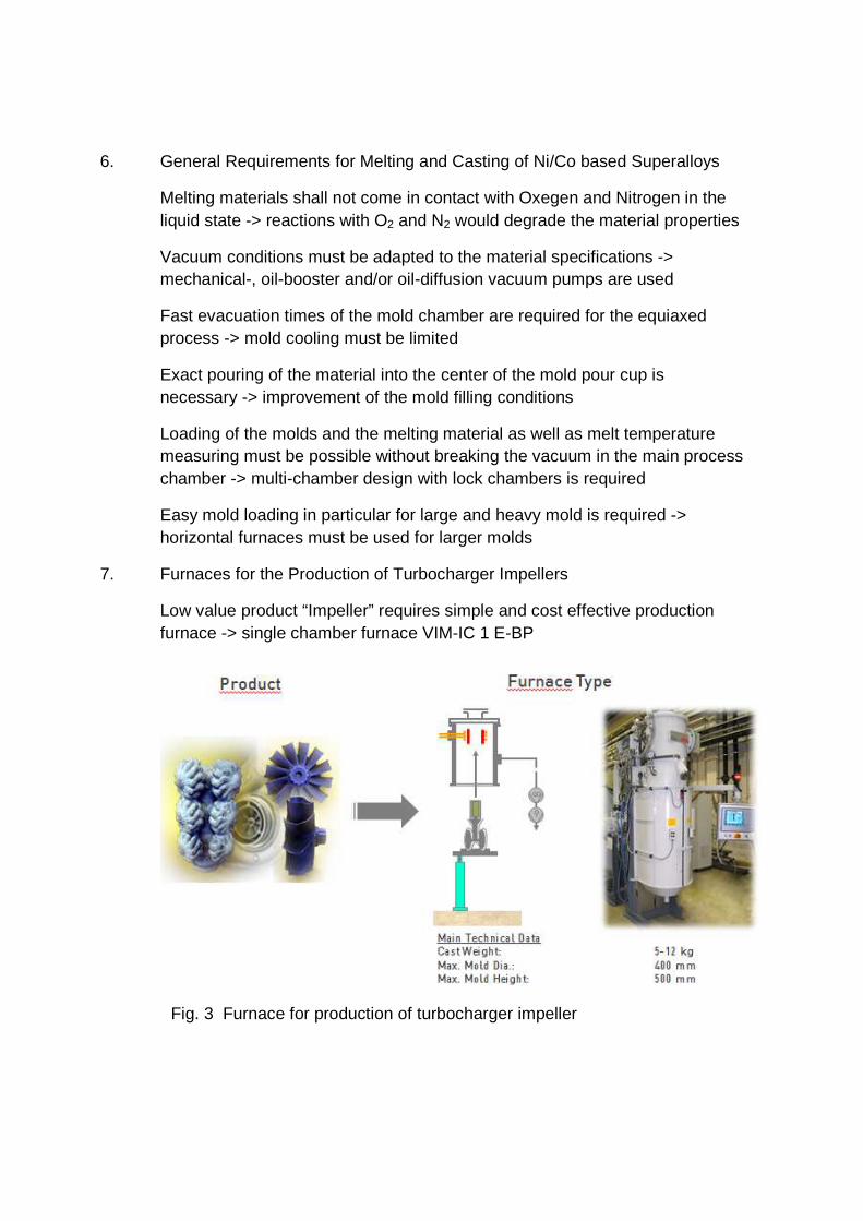
7. Furnaces for the Production of Turbocharger Impellers
Low value product “Impeller” requires simple and cost effective production furnace -> single chamber furnace VIM-IC 1 E-BP
Fig. 3 Furnace for production of turbocharger impeller

8. Vertical Furnace for the Production of small and medium size Blades, Vanes and Structural Parts for Gas Turbines
For cast weights up to 200kg and/or mold sizes up to diameter 1000mm x height 1200mm usually vertical furnaces are used
Fig. 4 Vertical Furnace for the Production of small and medium size Blades, Vanes and Structural Parts for Gas Turbines

9. Horizontal Furnace for the Production of Large Blades, Vanes and Structural
Parts for Gas Turbines For cast weights above 200kg and large mold sizes usually horizontal furnaces are used
Fig. 5 Horizontal Furnace for the Production of Large Blades, Vanes and Structural Parts for Gas Turbines
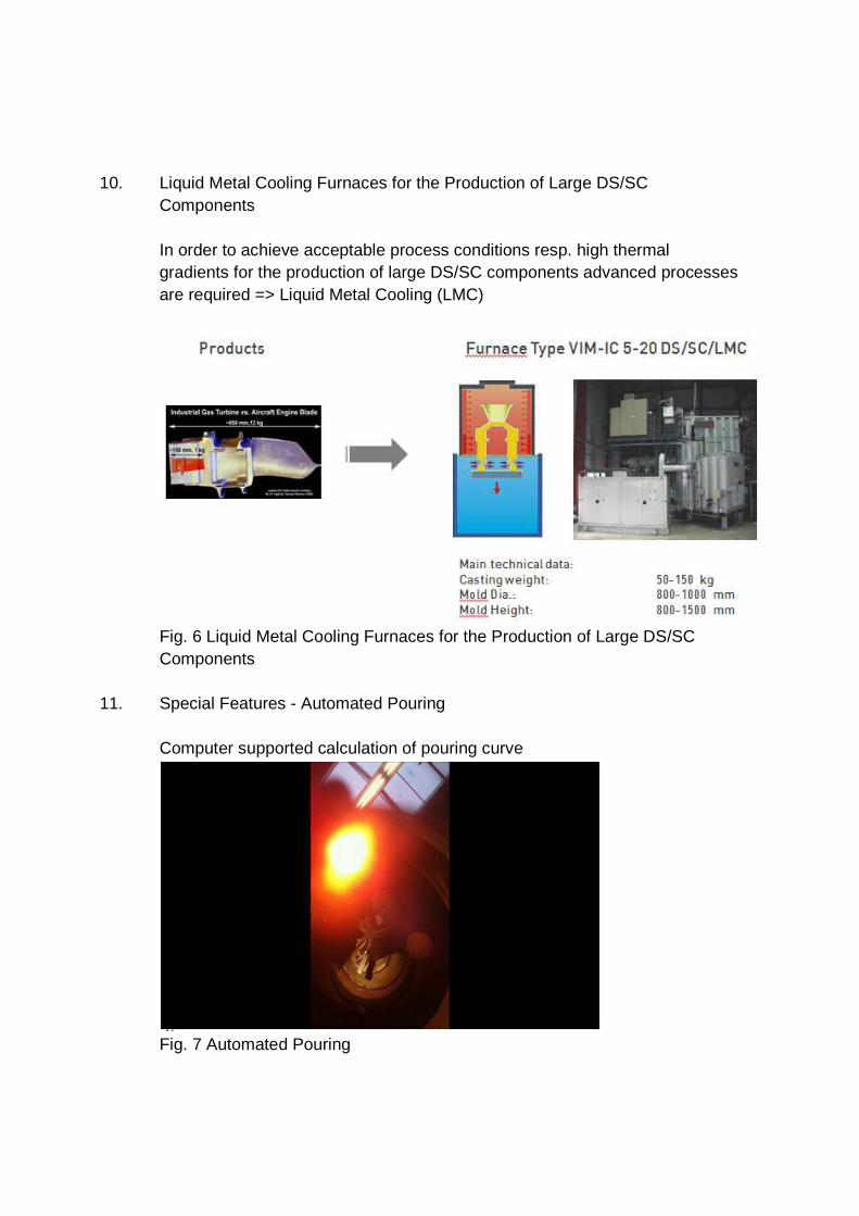
10. Liquid Metal Cooling Furnaces for the Production of Large DS/SC
Components In order to achieve acceptable process conditions resp. high thermal gradients for the production of large DS/SC components advanced processes are required => Liquid Metal Cooling (LMC)
Fig. 6 Liquid Metal Cooling Furnaces for the Production of Large DS/SC Components
11. Special Features - Automated Pouring Computer supported calculation of pouring curve
Fig. 7 Automated Pouring

12. Special Features - Centrifugal Casting for improved Mold Filling for Casting of Components with thin Sections
Fig. 8 Centrifugal Casting nits in VIM-IC Furnaces
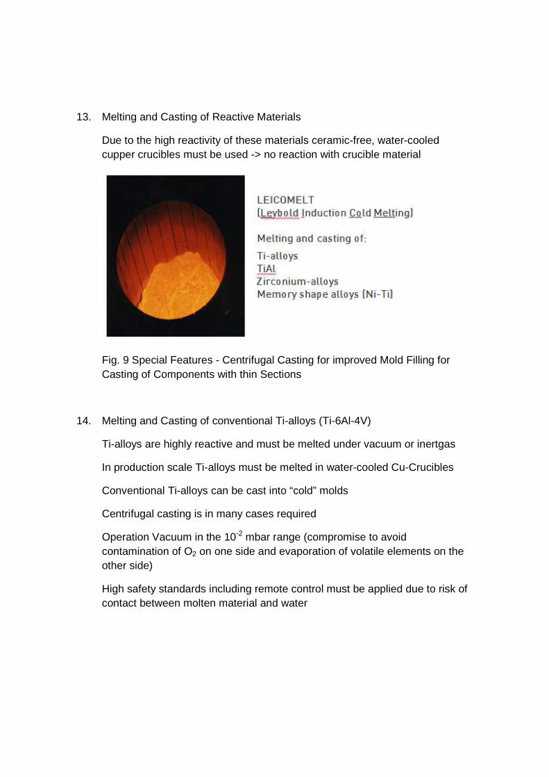
13. Melting and Casting of Reactive Materials
Due to the high reactivity of these materials ceramic-free, water-cooled cupper crucibles must be used -> no reaction with crucible material
Fig. 9 Special Features - Centrifugal Casting for improved Mold Filling for Casting of Components with thin Sections
14. Melting and Casting of conventional Ti-alloys (Ti-6Al-4V)
Ti-alloys are highly reactive and must be melted under vacuum or inertgas
In production scale Ti-alloys must be melted in water-cooled Cu-Crucibles
Conventional Ti-alloys can be cast into “cold” molds
Centrifugal casting is in many cases required
Operation Vacuum in the 10-2 mbar range (compromise to avoid contamination of O2 on one side and evaporation of volatile elements on the other side)
High safety standards including remote control must be applied due to risk of contact between molten material and water
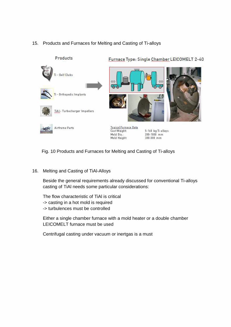
15. Products and Furnaces for Melting and Casting of Ti-alloys
Fig. 10 Products and Furnaces for Melting and Casting of Ti-alloys
16. Melting and Casting of TiAl-Alloys
Beside the general requirements already discussed for conventional Ti-alloys casting of TiAl needs some particular considerations:
The flow characteristic of TiAl is critical -> casting in a hot mold is required -> turbulences must be controlled
Either a single chamber furnace with a mold heater or a double chamber LEICOMELT furnace must be used
Centrifugal casting under vacuum or inertgas is a must

17. Typical Single Chamber LEICOMELT 12 TP with Mold Heater and Centrifugal Casting unit
Fig. 11 Typical Single Chamber LEICOMELT 12 TP with Mold Heater and Centrifugal Casting unit
18. Melting and Casting of Ti-Al Turbine Blades
Fig. 12 Typical Aircaft enginet

Typical Double Chamber LEICOMELT 5 Furnace for Melting and Casting of TiAl Blades
Fig. 13 Typical Double Chamber LEICOMELT 5 Furnace for Melting and Casting of TiAl Blades
19. Pouring of a TiAl Alloy
Fig. 14 Pouring of TiAL