Rapid Solidification
23
Chapter 3 Rapid Solidification H. JONES 3.1. INTRODUCTION The term solidification simply means formation of solid so the parent material(s) can be gaseous (vapor) or liquid (e.g., melt). Thus, solidification can involve continuous or dis- continuous deposition with or without a chemical reaction or passage of a solidification front through a volume of melt. The term rapid solidification is normally applied to solid- ification from the melt. The description "rapid" can be taken to imply a short-time interval between initiation and completion of solidification and a high velocity of propagation of the advancing solidification front. Such rapid solidification is most readily achieved by imposing a high cooling rate during solidification. This requires a thin layer, filament or droplet(s) of melt to be generated in good contact with an effective heat sink. Rapid solidification then occurs either directly, as a result of coupling between external heat ex- traction and the transport of latent and specific heat required to propagate the solidification front, or indirectly during the recalescence that follows nucleation of solidification at large undercooling. Rapid solidification processes such as melt-atomization, spray-deposition, splat-quenching, melt-spinning and planar flow-casting and their derivatives all gener- ate high cooling rates during solidification and their products contain structural features formed at different levels of prior undercooling. More control over the nucleation stages of rapid solidification can be obtained by slow cooling of a volume of melt (which can be quite large) that has been freed of agents than would otherwise catalyze nucleation at low undercooling. Nucleation of rapid solidification can then be triggered by contact with a nucleating phase at predetermined levels of undercooling, though in this case the slow cool that follows completion of solidification may be insufficient to preserve to ambient temperature some of the non-equilibrium features generated by the rapid solidification step. Correspondingly, growth velocity during rapid solidification can be coupled to the velocity of a heat source (such as a laser or electron beam) traversing the surface of a block of material. In this case the heat source generates a stable melt-pool which melts new ma- terial at its leading edge as fast as previously melted material refreezes at its trailing edge. Melting and freezing front velocities increase from zero at the bottom of the melt-pool to a value related to the traverse velocity at the sample surface. The present short survey is in three sections. The first section reviews methods of rapid solidification from the melt and their characteristics. The second section reviews current knowledge of the effects of 23
Transcript of Rapid Solidification
Chapter 3 Rapid Solidification
H. JONES
3.1. I N T R O D U C T I O N
The term solidification simply means formation of solid so the parent material(s) can be gaseous (vapor) or liquid (e.g., melt). Thus, solidification can involve continuous or dis- continuous deposition with or without a chemical reaction or passage of a solidification front through a volume of melt. The term rapid solidification is normally applied to solid- ification from the melt. The description "rapid" can be taken to imply a short-time interval between initiation and completion of solidification and a high velocity of propagation of the advancing solidification front. Such rapid solidification is most readily achieved by imposing a high cooling rate during solidification. This requires a thin layer, filament or droplet(s) of melt to be generated in good contact with an effective heat sink. Rapid solidification then occurs either directly, as a result of coupling between external heat ex- traction and the transport of latent and specific heat required to propagate the solidification front, or indirectly during the recalescence that follows nucleation of solidification at large undercooling. Rapid solidification processes such as melt-atomization, spray-deposition, splat-quenching, melt-spinning and planar flow-casting and their derivatives all gener- ate high cooling rates during solidification and their products contain structural features formed at different levels of prior undercooling. More control over the nucleation stages of rapid solidification can be obtained by slow cooling of a volume of melt (which can be quite large) that has been freed of agents than would otherwise catalyze nucleation at low undercooling. Nucleation of rapid solidification can then be triggered by contact with a nucleating phase at predetermined levels of undercooling, though in this case the slow cool that follows completion of solidification may be insufficient to preserve to ambient temperature some of the non-equilibrium features generated by the rapid solidification step. Correspondingly, growth velocity during rapid solidification can be coupled to the velocity of a heat source (such as a laser or electron beam) traversing the surface of a block of material. In this case the heat source generates a stable melt-pool which melts new ma- terial at its leading edge as fast as previously melted material refreezes at its trailing edge. Melting and freezing front velocities increase from zero at the bottom of the melt-pool to a value related to the traverse velocity at the sample surface. The present short survey is in three sections. The first section reviews methods of rapid solidification from the melt and their characteristics. The second section reviews current knowledge of the effects of
23
24 H. Jones
rapid solidification on constitution and microstructure formation. The third section gives examples of resulting property changes and of current or potential applications.
3.2. M E T H O D S OF R A P I D S O L I D I F I C A T I O N
These are most conveniently discussed under the headings droplet, spinning and surface melting technologies. Droplet technologies all involve generation of multiple or single droplets of melt which solidify either individually or in a state of partial or complete coa- lescence on a deposition surface. Spinning technologies involve stabilization of a flowing melt-stream so that it freezes as a continuous filament, ribbon or sheet in contact with a moving chill surface or heat extracting fluid. Surface melting technologies involve rapid melting at a surface followed by rapid freezing sustained by rapid heat extraction into the unmelted bulk. Cooling rates during solidification can reach 101~ K/s in cross sections as small as ~0 .1 / zm with undercoolings that can attain hundreds of K, front velocities as high as 100 m/s and solidification times as short as nanoseconds.
3.2.1 Droplet methods
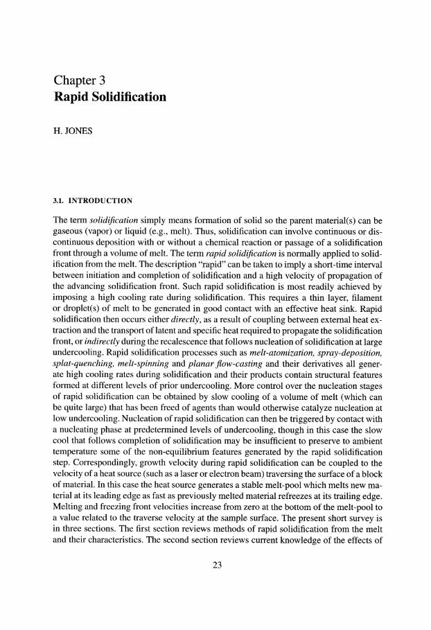
These are all variants of the long-established technology of making lead shot by teem- ing molten lead through a preheated steel dish perforated by an array of equal sized holes (Johnson et al. 1976). The fundamental principle is that a pendant drop or free falling melt-stream tends to break up into droplets as a result of surface tension. This process can be intensified, for example, by impingement of high velocity jets of a second fluid, by cen- trifugal force at the tip of a rotating cup or disc or by an applied electric field. The standard method, known as atomization, uses high velocity gas or water jets to rapidly fragment a volume of melt into large numbers of small droplets (Fig. 3.1) (Schmitt 1979). The jets form, propel and cool the droplets that may freeze completely in flight to form powder or
Metal Metal
Confined ~ II 1 Figure 3.1. Principle of spray droplet (atomization) by impingement of high velocity
gas jets on to a free falling or emergent melt-stream (Schmitt 1979).
Rapid Solidification
100
80 E 0 > 60 > .m
= 40 E 0
20
1
12.5
/ / / ~ . . . " 10.4 MPa
/ / / " ~ " ~ 1 7 . 3 M P a
I I I I 1 1 1 I I I I I I 1 1
10 100 Particle diameter (It m)
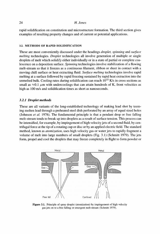
Figure 3.2. Particle size distribution for Sn-5wt%Pb alloy as a function of atomizing gas pressure (Anderson 1991).
25
may form individual splats or a thick deposit by impact on to a suitable substrate. Pow- der or shot particulate generated by such techniques displays a range of particle sizes and shapes even for a single set of operating conditions. Increasing atomizing gas pressure, for example, then increases the yield of finer particle sizes (Fig. 3.2) (Anderson 1991) while the more effective quench of water atomization leads to more irregular shapes. Al- though particles more or less identical in size and shape from the same powder sample can show quite different microstructures (because of different local conditions), smaller particles tend to cool more rapidly and/or undercool more prior to solidification so tend to solidify more rapidly (i.e., at higher front velocity). Splats formed from droplets of given size tend to solidify even more rapidly because of more effective heat extraction from the larger surface area they offer, especially when at least one of their surfaces is in good contact with an efficient heat sink, such as a water-cooled rotating copper drum. A spray deposit can maintain the same microstructure as the equivalent splats provided that their solidification time is sufficiently less than the time interval between deposition of succes- sive splats at a given location on the substrate (Oguchi et al. 1990). Atomizers range in size from laboratory units with capacities of less than 1 kg per run to commercial scale fa- cilities with capacities as large as 50,000 tonnes per year (Anon 1989). Powders destined for high performance applications tend to be atomized with inert gases or in vacuum to minimize formation of oxides or other potentially damaging inclusions.
The variability of powder particle sizes, shapes and microstructures within bulk atom- ized powder samples, splats and spray deposits (which is acceptable for many purposes), and the need to consolidate the materials for typical engineering applications, has stim- ulated work on droplet methods that employ lower cooling rates and allow measurement or control of the temperature at which nucleation occurs. Such methods include emulsi- fication techniques in which a distribution of droplets is produced within a carrier liquid which can be inert, which can act as a flux for impurities in the droplets that otherwise would activate nucleation at low undercoolings or which can trigger nucleation at a spe-
26 H. Jones
cific undercooling (Perepezko 1984). A variant uses rapid solidification to produce a fine secondary network of eutectic in a single- phase matrix. This network is then spheroidized by heat treatment above the solidus to produce a distribution of liquid droplets in the solid matrix (Prasad et al. 1984). Information regarding melting and nucleation temperatures of the droplets can then be obtained by controlled heating and cooling coupled with dif- ferential calorimetry, and the results related to microstructures formed in the solidified droplets (Kim and Cantor 1994). Undercoolings of hundreds of degrees can be gener- ated in relatively large volumes of melt by prior removal of impurities e.g., by fluxing (Kui et al. 1984), by levitation (containerless) melting (Weber et al. 1991), or by induc- tion remelting in contact with a water-cooled copper hearth. A recent triumph of this latter approach has been to form substantial pieces of zirconium-based metallic glasses that dis- play ultra-high strengths and good fatigue characteristics along with extensive plasticity in the supercooled liquid range (Johnson 1996). Benefits of the related levitation melting approach have included much fundamental information on the formation of solidification microstructures at very high undercoolings and growth velocities that cannot be accessed by other rapid solidification techniques (Herlach 1994, Herlach et al. 1993).
3.2.2 Spinning methods
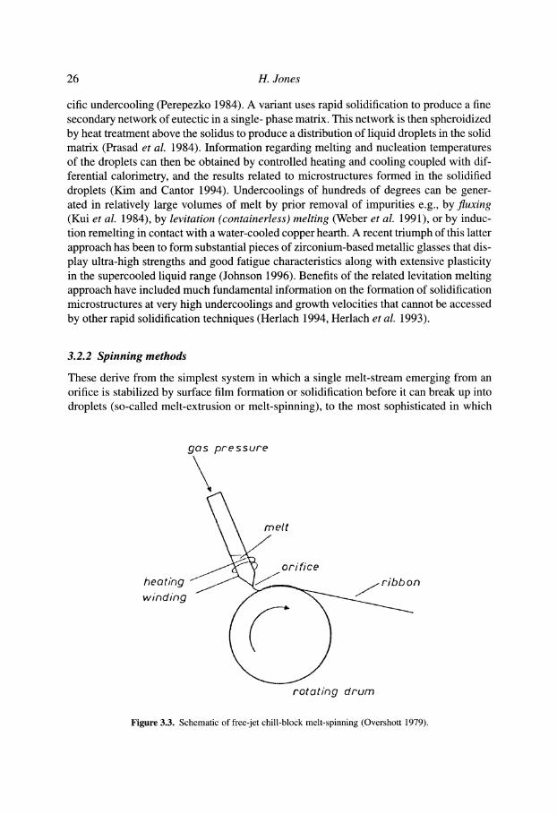
These derive from the simplest system in which a single melt-stream emerging from an orifice is stabilized by surface film formation or solidification before it can break up into droplets (so-called melt-extrusion or melt-spinning), to the most sophisticated in which
heoting winding
gas pressure
eit
. / ~ ~ /orifice /ribbon
rotot/ng drum
Figure 3.3. Schematic of free-jet chill-block melt-spinning (Overshott 1979).
Rapid Solidification 27
one or more melt-streams are used to make wide or composite ribbons by impingement on single or twin chill roll surfaces. In standard free-jet chill-block melt-spinning (Fig. 3.3) (Overshott 1979) the melt-stream forms a single ribbon typically 10 to 50 # m thick and a few millimeters wide by impingement on to a single chill roll rotating at a surface speed of some tens of meters per second. In planar flow-casting the distance from the nozzle orifice to the chill surface is reduced to less than ~0.5 mm to eliminate formation of a melt-pool and associated instabilities. Thin strips up to 500 mm wide have been cast in tonnage quantities by this method, either for direct application or pulverization into platelet particulate for consolidation into other product forms. Melt-extraction (Maringer and Mobley 1974), in which the rotating chill roll forms the products by direct contact with the surface of a crucible of melt or the melted extremity of the solid electrode, and its derivative melt-overflow (Boulby and Wood 1986a, b), do not involve generating a melt-stream. Continuous rapidly solidified filament with round section can be produced by the rotating water bath process in which a melt-stream emerging from a cylindrical orifice is solidified directly on entry into a rotating annulus of water contained within the lip of a rotating water bath (Ohnaka 1985). This process can also be used to generate powder particulate when the conditions result in the break-up of the melt-stream on entry into the water bath (Raman et al. 1982). Free-jet chill-block melt-spinning and melt- extraction can be used to generate a flake product directly if continuity is interrupted by a series of regularly-spaced notches on the chill-block. Melt-spun ribbon or planar flow cast sheet can be pulverised, for example, by means of a blade-cutter mill (Gelinas et al. 1988, Pelletier et al. 1990) into platelets (_~0.3 mm across). These provide a more suitable feedstock for consolidation by powder metallurgy than continuous ribbon, for example, which exhibits a much lower packing density.
3.2.3 Surface-melting methods
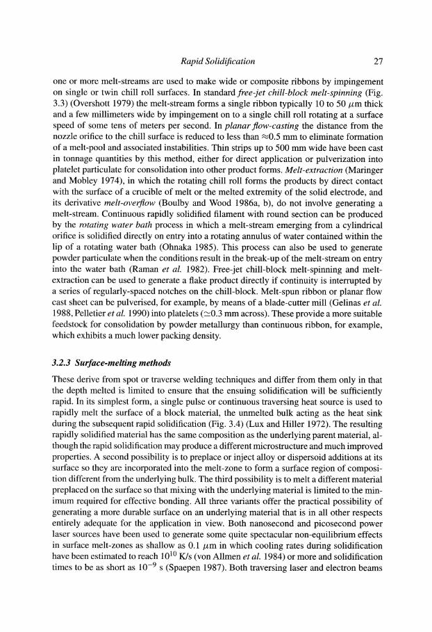
These derive from spot or traverse welding techniques and differ from them only in that the depth melted is limited to ensure that the ensuing solidification will be sufficiently rapid. In its simplest form, a single pulse or continuous traversing heat source is used to rapidly melt the surface of a block material, the unmelted bulk acting as the heat sink during the subsequent rapid solidification (Fig. 3.4) (Lux and Hiller 1972). The resulting rapidly solidified material has the same composition as the underlying parent material, al- though the rapid solidification may produce a different microstructure and much improved properties. A second possibility is to preplace or inject alloy or dispersoid additions at its surface so they are incorporated into the melt-zone to form a surface region of composi- tion different from the underlying bulk. The third possibility is to melt a different material preplaced on the surface so that mixing with the underlying material is limited to the min- imum required for effective bonding. All three variants offer the practical possibility of generating a more durable surface on an underlying material that is in all other respects entirely adequate for the application in view. Both nanosecond and picosecond power laser sources have been used to generate some quite spectacular non-equilibrium effects in surface melt-zones as shallow as 0.1 /xm in which cooling rates during solidification have been estimated to reach 10 l~ K/s (von Allmen et al. 1984) or more and solidification times to be as short as 10 -9 s (Spaepen 1987). Both traversing laser and electron beams
28 H. Jones
I! [1-- electron beam II II II
refined zo workpiece
portion refined Dy remeltincj \~,~,b~6. "~('e" k . )
Figure 3.4. Principle of rapid solidification at the surface of a block of material following local melting with a traversing heat source (Lux and Hiller 1972).
have been used to treat entire surfaces via repeated incremental lateral displacement of the beam by the width of the melt-zone at the start of each new traverse (Lux and Hiller 1972). Samples with crack-free, relatively smooth treated surfaces can now be produced by appropriate control of the process parameters. The technique can also be used to de- velop coupling between the traversing beam and the solidification front so that the effects on resulting microstructure of systematic variations in front velocity up to -~ 1 m/s can be determined experimentally (Boettinger et al. 1984, Zimmermann et al. 1989). (See also Chapter 5 on "Laser Processing" by K.E Kobayashi in this book.)
3.3. C O N S T I T U T I O N AND M I C R O S T R U C T U R E FORMATION BY RAPID
SOLIDIFICATION
Rapid solidification produces changes in constitution because the large undercoolings and front velocities involved promote formation of non-equilibrium phases and extensions in composition range of surviving equilibrium phases. Microstructural differences include changes in mode of growth and size refinement as a result of the short diffusion distances imposed. These aspects will be dealt with separately.
Rapid Solidification 29
3.3.1 Non-equilibrium constitution
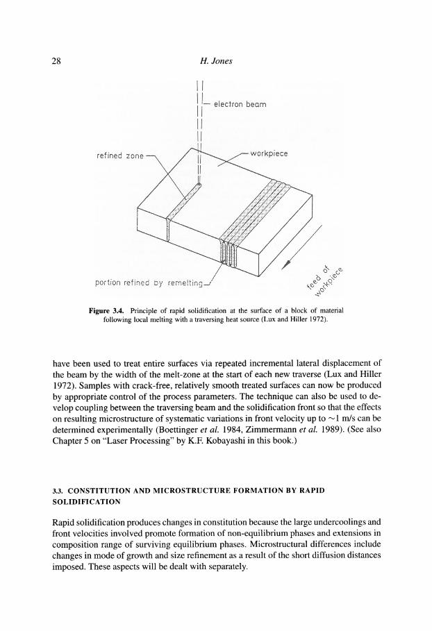
Non-equilibrium phases formed by rapid solidification include glasses, quasicrystalline phases, new crystalline phases and equilibrium phases with extended composition ranges. Glass formation requires that the entire or residual melt is undercooled below the glass-forming temperature before the advance of crystal formation can complete the solidification process. Glass formation is highly sensitive to composition, with pure metallic melts in particular requiring very high cooling rates during solidifica- tion to suppress the rapid advance of crystal formation. Alloy systems showing deep eutectics, however, form glasses rather more readily in the composition ranges near to these eutectics. Critical cooling rates for glass formation can be predicted by modelling the nucleation and growth of the competing crystalline (or quasicrystalline) phases. The melt will become a glass if cooling is rapid enough not to intersect the knee of the time-temperature-transformation (TTT) curve of the competing crystal form- ing process (Fig. 3.5) (Davies et al. 1974). In the absence of such diagrams, easy or bulk glass formation has been variously associated with ratio of glass formation to melting temperatures, large intervals between glass formation and crystallization temperatures (the so-called "supercooled liquid" range), low thermodynamic driving force for crystallization, large negative heats of mixing, simultaneous precipitation of more than one phase, large atomic size differences between the components, as well as deep eutectic formation (Peker and Johnson 1993, Massalski et al. 1981, In- oue et al. 1993). (See also Chapter 14 on "Bulk Amorphous Alloys" by A. Inoue in
2000
TF
1". 1000
Figure 3.5.
" I I ' ' I ' I I I ' " I - I
Ni a'm i "==m ~ I ,.,==..-- ~ ...===,. ,.==-- ,=.,m ,.~ ~ m
! m lllmlllm ]
<1
_1_ ,,
m I , m_ I_ i i m m
10 - 8 i ~ " - N 1 0 - 6 10 - 4 10 - 2 1
T I M E in sec
Predicted temperature-time curve for initiation of crystallization of undercooled liquid nickel (Davies et al. 1974).
30 H. Jones
50
40
0 E
3 0 - v
-r- 2 o - <]
l O -
I O~
1 - 5 0
� 9
� 9
Hf Sc
� 9
f
/o osb / Sn
/
/ Ti �9 Ta Pu /
�9 �9 / P / Nb �9
�9 / Mo 8 0 �9 / Ge In
/ v 13Si 0 Cr \ 0
A u 0
1 1 i I
- 4 0 - 3 0 - 2 0 - 1 0 0 10
A H (KJ tool " I) M
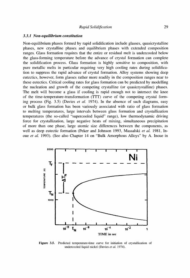
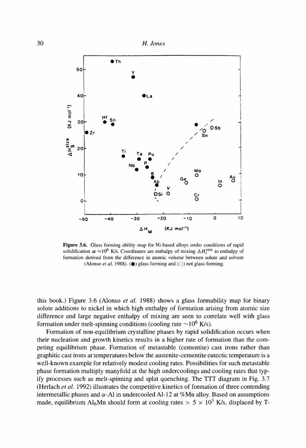
Figure 3.6. Glass forming ability map for Ni-based alloys under conditions of rapid solidification at ,~106 K/s. Coordinates are enthalpy of mixing A H~ size to enthalpy of formation derived from the difference in atomic volume between solute and solvent
(Alonso et al. 1988). ( � 9 glass forming and (O) not glass forming.
this book.) Figure 3.6 (Alonso et al. 1988) shows a glass formability map for binary solute additions to nickel in which high enthalpy of formation arising from atomic size difference and large negative enthalpy of mixing are seen to correlate well with glass formation under melt-spinning conditions (cooling rate ~ 106 K/s).
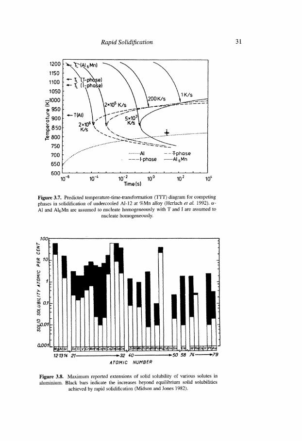
Formation of non-equilibrium crystalline phases by rapid solidification occurs when their nucleation and growth kinetics results in a higher rate of formation than the com- peting equilibrium phase. Formation of metastable (cementite) cast irons rather than graphitic cast irons at temperatures below the austenite-cementite eutectic temperature is a well-known example for relatively modest cooling rates. Possibilities for such metastable phase formation multiply manyfold at the high undercoolings and cooling rates that typ- ify processes such as melt-spinning and splat quenching. The TTT diagram in Fig. 3.7 (Herlach et al. 1992) illustrates the competitive kinetics of formation of three contending intermetallic phases and or-A1 in undercooled Al-12 at %Mn alloy. Based on assumptions made, equilibrium A16Mn should form at cooling rates > 5 • 103 K/s, displaced by T-
Rapid Solidification 31
1 2 0 0
1 1 5 0
1 1 0 0
1050
~.I000
o~ 950
9OO
'~ 850 Q.
E ~_ 800
750
700
650
ase} \ \
\ \ \2ooK/~ ~ - ~
4-- T(AI} . ' I ,-"'" 5x19'~ { 2.106 / ttt" K/s I~ K/S kx k.\. ~k~ 4. ~ . . . . . . . . . . . . . . . . . . . .
. . . . . . . . . . .
,, ....... - . . . . . . . A I - - - T - p h o s e
,. . . . . I - p h a s e . . . . . AI 6 M n
600 . . . . . . . . . . . . . . . . . . . . . . . . . . . . . . . . . . . . . . . . . . . . .
10 "6 10 -l" 10 -2 10 0 10 2 10 ~ Time(s)
Figure 3.7. Predicted temperature-time-transformation (TTT) diagram for competing phases in solidification of undercooled AI-12 at %Mn alloy (Herlach et aL 1992). ~- A1 and A16Mn are assumed to nucleate homogeneously with T and I are assumed to
nucleate homogeneously.
100 I,.,.
~o cL
~ 0.1
~.o~
&OOf
I
i -
F
I
,
A~Si Sc Ti
121314 21 . . . . . . . . . . . . . . ~ 32 40
A TOM/C NUMBER
. . . . . . . . . . . . . . i
": 50 58 74-" - -~79
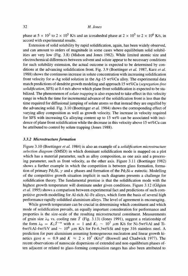
Figure 3.8. Maximum reported extensions of solid solubility of various solutes in aluminum. Black bars indicate the increases beyond equilibrium solid solubilities
achieved by rapid solidification (Midson and Jones 1982).
32 H. Jones
phase at 5 x 10³ to 2 x 10⁵ K/s and an icosahedral phase at 2 x 10⁵ to 2 x 10⁶ K/s, in accord with experimental results.
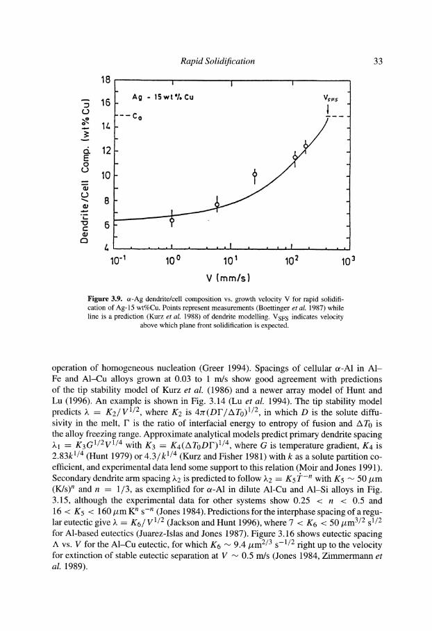
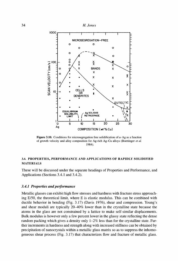
Extension of solid solubility by rapid solidification, again, has been widely observed, and can amount to orders of magnitude in some cases where equilibrium solid solubil- ities are very low (Fig. 3.8) (Midson and Jones 1982). While limited atomic size and electrochemical differences between solvent and solute appear to be necessary conditions for such solubility extension, the actual outcome is expected to be determined by con- ditions at the advancing solidification front. Fig. 3.9 (Boettinger et al. 1987, Kurz et al. 1988) shows the continuous increase in solute concentration with increasing solidification front velocity for ot-Ag solid solution in the Ag-15 wt%Cu alloy. The experimental data match predictions of dendrite growth modeling and approach 15 wt%Cu (segregation-free solidification, SFS) at 0.4 m/s above which plane front solidification is expected to be sta- bilized. The phenomenon of solute trapping is also expected to take effect in this velocity range in which the time for incremental advance of the solidification front is less than the time required for diffusional jumping of solute atoms so that instead they are engulfed by the advancing solid. Fig. 3.10 (Boettinger et al. 1984) shows the corresponding effect of varying alloy composition as well as growth velocity. The increase in velocity required for SFS with increasing Cu alloying content up to 15 wt% can be associated with inci- dence of plane front solidification while the decrease in this velocity above 15 wt%Cu can be attributed to control by solute trapping (Jones 1988).
3.3.2 Microstructure formation
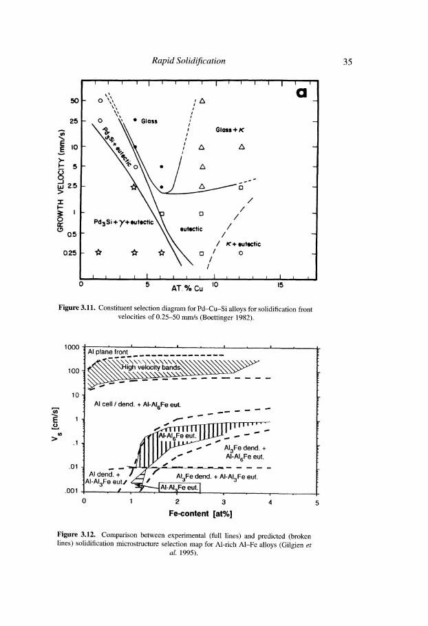
Figure 3.10 (Boettinger et al. 1984) is also an example of a solidification microstructure selection diagram (SMSD) in which dominant solidification mode is mapped on a plot which has a material parameter, such as alloy composition, as one axis and a process- ing parameter, such as front velocity, as the other axis. Figure 3.11 (Boettinger 1982) shows a further example in which the competition is between glass formation, forma- tion of primary Pd3Si, y and x phases and formation of the Pd3Si-K eutectic. Modelling of the competitive growth situation implicit in such diagrams presents a challenge for solidification theory. The fundamental premise is that the solidification mode with the highest growth temperature will dominate under given conditions. Figure 3.12 (Gilgien et al. 1995) shows a comparison between experimental fact and predictions of such com- petitive growth modelling for Al-rich A1-Fe alloys, which form the basis of several high performance rapidly solidified aluminium alloys. The level of agreement is encouraging.
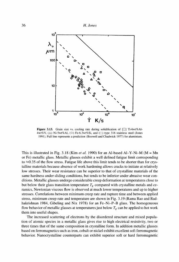
While growth temperature can be crucial in determining which constituent and which mode of solidification prevails, an equally important consideration for performance and properties is the size-scale of the resulting microstructural constituent. Measurements of grain size ~.0 vs. cooling rate T (Fig. 3.13) (Jones 1991), suggest a relationship of the form ~.0 - KlJ ' -n with n -- 1 and K1 ~ 107 #m K/s for Ni-5wt%A1 and Ti- 6wt%A1-4wt%V and ~ 106 #m K/s for Fe-6.3wt%Si and type 316 stainless steel. A prediction for pure aluminium assuming homogeneous nucleation and linear growth ki- netics gave n = 0.9 and K ~ 2 x 10⁷ (K/s) n (Boswell and Chadwick 1977). The recent observations of nanoscale dispersions of extended and non-equilibrium phases of- ten adjacent or related to glass-forming composition ranges has also been attributed to
Rapid Solidification 33
r
c~ E o
t_)
J w
r t_)
f . . .
r-
C]
18 i
A g - 1 5 w t % C u 16
- - - C O
12
10
8 -r
10 -1 10 0
�9 . . ! , , ~ . I , .
101 I0 z
V {rnrn/s )
i |
10 3
Figure 3.9. ot-Ag dendrite/cell composition vs. growth velocity V for rapid solidifi- cation of Ag-15 wt%Cu. Points represent measurements (Boettinger et al. 1987) while line is a prediction (Kurz et al. 1988) of dendrite modelling. VSF s indicates velocity
above which plane front solidification is expected.
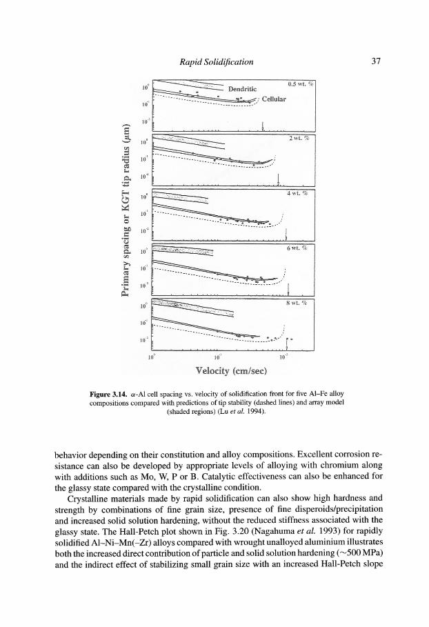
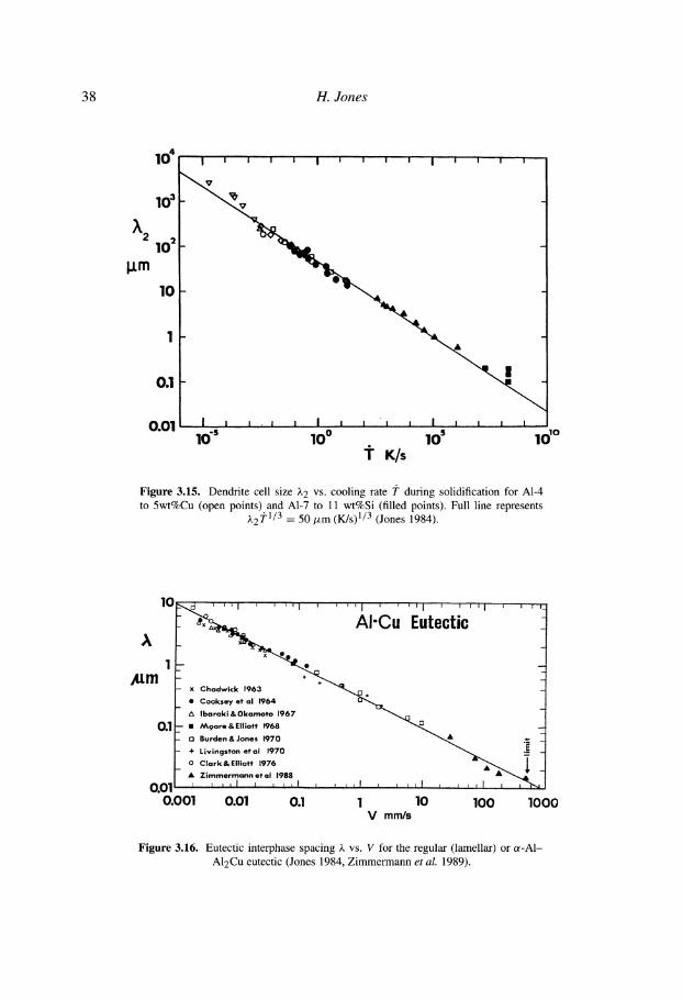
operation of homogeneous nucleation (Greer 1994). Spacings of cellular or-A1 in A1- Fe and A1-Cu alloys grown at 0.03 to 1 m/s show good agreement with predictions of the tip stability model of Kurz et al. (1986) and a newer array model of Hunt and Lu (1996). An example is shown in Fig. 3.14 (Lu et al. 1994). The tip stability model predicts ,k = K2/V 1/2, where K2 is 4Jr(DF/ATo) 1/2, in which D is the solute diffu- sivity in the melt, 1-" is the ratio of interfacial energy to entropy of fusion and AT0 is the alloy freezing range. Approximate analytical models predict primary dendrite spacing )~1 = K3G1/2V 1/4 with K3 = K4(AToDI') 1/4, where G is temperature gradient, K4 is 2.83k 1/4 (Hunt 1979) or 4.3/k 1/4 (Kurz and Fisher 1981) with k as a solute partition co- efficient, and experimental data lend some support to this relation (Moir and Jones 1991). Secondary dendrite arm spacing )~2 is predicted to follow )~2 -- K5 i ?-n with K5 "~ 50/xm (K/s) n and n = 1/3, as exemplified for or-A1 in dilute A1-Cu and AI-Si alloys in Fig. 3.15, although the experimental data for other systems show 0.25 < n < 0.5 and 16 < K5 < 160 # m K n s -n (Jones 1984). Predictions for the interphase spacing of a regu- lar eutectic give )~ = K6/V 1/2 (Jackson and Hunt 1996), where 7 < K6 < 50 # m 3/2 s 1/2 for Al-based eutectics (Juarez-Islas and Jones 1987). Figure 3.16 shows eutectic spacing A vs. V for the A1-Cu eutectic, for which K6 ~ 9.4 # m 2/3 s-1/2 right up to the velocity for extinction of stable eutectic separation at V ~ 0.5 rrds (Jones 1984, Zimmermann et al. 1989).
34 H. Jones
I000
I00
E >-
q bJ
Z < I0 if)
I 0
Ag
I t I I I -
M I C R O S E G R E G A T I O N - FREE o o _
o o _
- o / X X ~ - o / x x ~ o :
o .•215 x o x _
�9 �9 CELLS " \ I " -6~- , \ x I
�9 ' E
" , , , ~ U T E C T I C /
�9 �9 �9 o ~ " " ~ X k
EQUILIBRIUM ~ e . . , . , \ [ ,& l o~-uB,-,-~: / A~ s o u o u s \ ~ _ I- �9 ""_"iM,:i"" \ / RE-TROORAOE �9 '.,~EI
I I I I ! ! ~ l 5 I0 15 20 25 30
COMPOSITION (wt % Cu)
Figure 3.10. Conditions for microsegregation free solidification of a-Ag as a function of growth velocity and alloy composition for Ag-rich Ag-Cu alloys (Boettinger et al.
1984).
3.4. P R O P E R T I E S ~ P E R F O R M A N C E AND A P P L I C A T I O N S OF R A P I D L Y S O L I D I F I E D
M A T E R I A L S
These will be discussed under the separate headings of Properties and Performance, and Applications (Sections 3.4.1 and 3.4.2).
3.4.1 Properties and performance
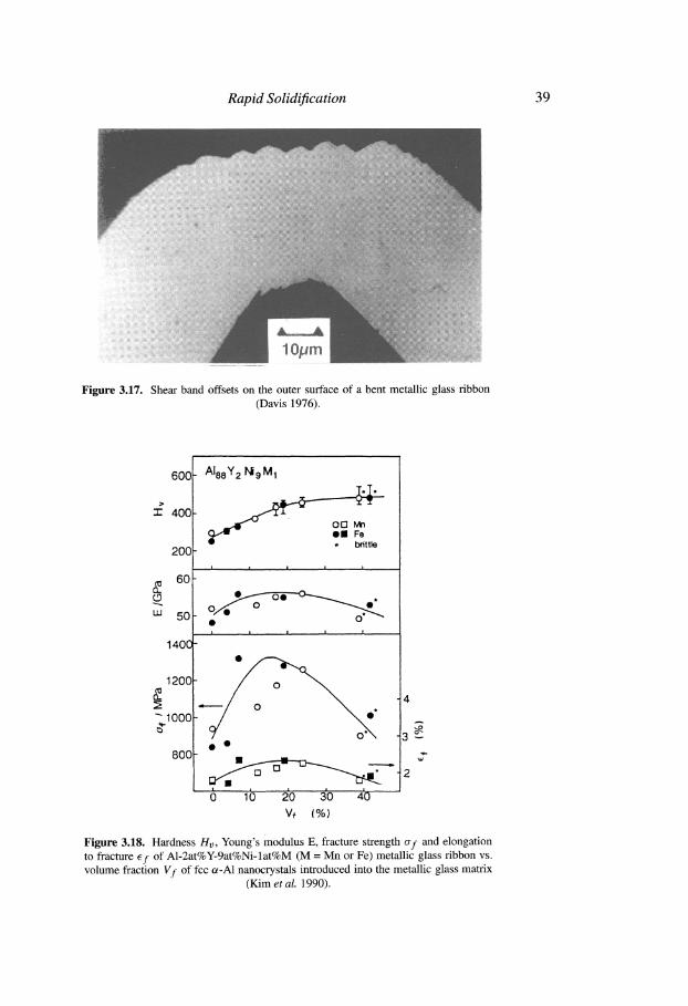
Metallic glasses can exhibit high flow stresses and hardness with fracture stress approach- ing E/50, the theoretical limit, where E is elastic modulus. This can be combined with ductile behavior in bending (Fig. 3.17) (Davis 1976), shear and compression. Young's and shear moduli are typically 20-40% lower than in the crystalline state because the atoms in the glass are not constrained by a lattice to make self-similar displacements. Bulk modulus is however only a few percent lower in the glassy state reflecting the dense random packing which gives a density only 1-2% less than for the crystalline state. Fur- ther increments in hardness and strength along with increased stiffness can be obtained by precipitation of nanocrystals within a metallic glass matrix so as to suppress the inhomo- geneous shear process (Fig. 3.17) that characterizes flow and fracture of metallic glass.
Rapid Solidification
2 5 A
E E I 0
>- ~- 5 m
~ 2 . 5 > ::E I'--
tw (..9
0.5
0.25
, i ' 1 I J ~ I ~ I t i i ' i I
- o ~, ,/X \~ / \',
- ~ ~ \ 0 ' �9 Gloss / %~ \\ / Gio,=+x
~o~._ ~ " / - / z~ A \ - ~ \
_ N ~ g �9 /k
- D /
_ Pd 3 s i + X + ~ " e u t ~ t i c / / /
\ ~ / K + eut tc t ie - "~' ~ r \ ~ o / / o
\ \ /
J I I l 1 l 1 ~ ~ I ~ I A l I I 0 5 A T . % C u l0 15
!
a
Figure 3.11. Constituent selection diagram for Pd-Cu-Si alloys for solidification front velocities of 0.25-50 mm/s (Boettinger 1982).
35
E u L - - - ,
r
>
1000
100
10
.01
.001
AI p lane front ' . . . . . . . '
- ~,~,-,~ , - , i ,-,2\", '~ . . . . . . . .
. = .
AI cell / dend. + AI-AIsFe eul.
, ~ T I T I T I T 1 1 ] T r r [ ~ I - l ~ T r ' - ' -
/ ! I I I I W % -- " AI3F e dend- + ,/111 LV . ' " AI-AI,Fe eat
AI den~. +" - - ~ - J / ~ " "-s "-A/F~ d e n d ~ 1 2 1 ; e ;ut" " ~l-Al,,Feeut,l ~ t ~ 3 -, - " 3 "
" . / , ~ P ~ ' I . AI-AI,'}FeeutI,,, ,
0 1 2 3 4
Fe-content [at%]
Figure 3.12. Comparison between experimental (full lines) and predicted (broken lines) solidification microstmcture selection map for Al-rich A1-Fe alloys (Gilgien et
al. 1995).
36 H. Jones
lOO
104 10 ~ 106 10"
"i" K/s Figure 3.13. Grain size vs. cooling rate during solidification of [[5]] Ti-6wt%Al- 4wt%V, (A) Ni-5wt%A1, (~) Fe-6.3wt%Si, and (�9 type 316 stainless steel (Jones
1991). Full line represents a prediction (Boswell and Chadwick 1977) for aluminium.
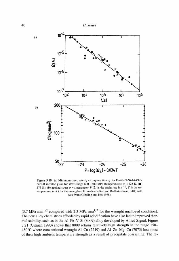
This is illustrated in Fig. 3.18 (Kim et al. 1990) for an Al-based A1-Y-Ni-M (M = Mn or Fe) metallic glass. Metallic glasses exhibit a well defined fatigue limit corresponding to ,~0.35 of the flow stress. Fatigue life above this limit tends to be shorter than for crys- talline materials because absence of work hardening allows cracks to initiate at relatively low stresses. Their wear resistance can be superior to that of crystalline materials of the same hardness under sliding conditions, but tends to be inferior under abrasive wear con- ditions. Metallic glasses undergo considerable creep deformation at temperatures close to but below their glass transition temperature Tg compared with crystalline metals and ce- ramics, Newtonian viscous flow is observed at much lower temperatures and up to higher stresses. Correlations between minimum creep rate and rupture time and between applied stress, minimum creep rate and temperature are shown in Fig. 3.19 (Rama Rao and Rad- hakrishnan 1984, Gibeling and Nix 1978) for an Fe -Ni -P-B glass. The homogeneous flow behavior of metallic glasses at temperatures just below Tg can be applied to hot work them into useful shapes.
The increased scattering of electrons by the disordered structure and mixed popula- tion of atomic species in a metallic glass gives rise to high electrical resistivity, two or three times that of the same composition in crystalline form. In addition metallic glasses based on ferromagnetics such as iron, cobalt or nickel exhibit excellent soft ferromagnetic behavior. Nanocrystalline counterparts can exhibit superior soft or hard ferromagnetic
Rapid Solidification
10 ~
10-'
10 -2
~L 10 ~
, ~ 10"
t., 10 2
0 .5 wt . % Dendritic
Cellular
2 w t . %
~=~ 4 w t . % e,~ 10~
$=I 101 !
~ 10"2 l o~t . . . . . . . . . . . . . . . . . .
~g ] .... . ~ ~, . . 6wt.% 10 ~ .
02
10 "1
" ~ 10"2 " . . . . . . . . . . . . . . . . . . 1
8 w t . %
- ,
10 ~
10 -1
10 .2
10 ~ 10 "1 10 .2
Velocity (cm/sec)
Figure 3 . 1 4 . a - A 1 cell spacing vs. velocity of solidification front for five A1-Fe alloy compositions compared with predictions of tip stability (dashed lines) and array model
(shaded regions) (Lu e t al. 1 9 9 4 ) .
37
behavior depending on their constitution and alloy compositions. Excellent corrosion re- sistance can also be developed by appropriate levels of alloying with chromium along with additions such as Mo, W, P or B. Catalytic effectiveness can also be enhanced for the glassy state compared with the crystalline condition.
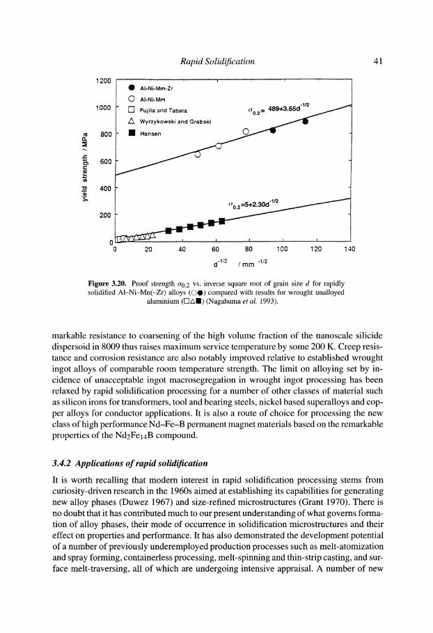
Crystalline materials made by rapid solidification can also show high hardness and strength by combinations of fine grain size, presence of fine disperoids/precipitation and increased solid solution hardening, without the reduced stiffness associated with the glassy state. The Hall-Petch plot shown in Fig. 3.20 (Nagahuma et al. 1993) for rapidly solidified A1-Ni-Mn(-Zr) alloys compared with wrought unalloyed aluminium illustrates both the increased direct contribution of particle and solid solution hardening ('~500 MPa) and the indirect effect of stabilizing small grain size with an increased Hall-Petch slope
38 H. J o n e s
10 4 I i i w i I i i , ~ I i i =
V
103 ~'.
~2 102
l.Lm
10
I
0.1
0.01 I I I . I ! I I I I I I I 1, i t
10 "s 100 10 s 101~ "1" K/s
Figure 3.15. Dendrite cell size ~-2 vs. cooling rate J" during solidification for A1-4 to 5wt%Cu (open points) and A1-7 to 11 wt%Si (filled points). Full line represents
),2 j"l/3 = 50 #m (K/s) 1/3 (Jones 1984).
~ m
10
01
o . Eote0t,0
x C h a d w i c k 196 .
�9 Cooksey . t a l 1 9 6 4
- A I b a r a k i & O k a m o t o 1967
M 9 o r e & El l iot t 1968
13 Burden & Jones 1970 �9
- + L i v i ngs ton et al 1970
_ o C l a r k & E l l i o t t 1976
�9 Z i m m e r m a n n et al 1988 I r i l l I ~ I , f 0.011 , , , ,!
0.001 0.01 0.1 1
' "~1 ~ J r~__
10 100 1000 V mm/s
Figure 3.16. Eutectic interphase spacing ,~ vs. V for the regular (lamellar) or a-A1- A12Cu eutectic (Jones 1984, Zimmermann et al. 1989).
39
(,,.~~ ,; %!~i 5:.i%
�9 ,,,,,r
Rapid Solidification
............ i iiii!iiiiiiiiiii!!ii !ii!i!!! i!i!i!ii!iii!ii ! i i iii i !!!i;ii!ii!!!i!!!i!i!iiiiiiii!i!ii!i!!ii!ii!ii!i:!!i i~iii~iiiiiii~i!i!iii!iii~ii~iii~i~i~!ii~iiiii~i~ii~i~iiiii~ii~;i~!~ii~!iii!iii~ii!~i~iiii~i~iii~iii iiii!iiii!!ii~iii!~iiii~iii~iiiiii~i~i
~!i!iii!i!iiiiiiiiiiiiiiiiiiii!iiiii!iiiii!iiiiiiiiiiiiiiii i iiiiliiiiiiiii!iiiiiiiiiiiii!iiiiiiiiiiiiiiiiiiiiiiiiiii
..................................................................................................................................... iiiiii!i!iiiiiiiiiiiiiiiii!iiiiiiiiiiiiiiiiiiiiii!i
Figure 3.17. Shear band offsets on the outer surface of a bent metallic glass ribbon (Davis 1976).
6 0 0
"r" 4 0 0
2 0 0
60, EL (..9
uJ 5 0
1 4 0 0
1 2 0 0 d3
EL
- 1 0 0 0
800
6 ~b 2'o 3'o 4'0 V~ ( % )
_ AleeY 2 N i 9 M 1
~ 1~ ol21 Mn @11 Fe * brittle
I , I I I I
. . . . .
3~ w
2
Figure 3.18. Hardness Hv, Young's modulus E, fracture strength af and elongation to fracture Ef of A1-2at%Y-9at%Ni-lat%M (M = Mn or Fe) metallic glass ribbon vs. volume fraction Vf of fcc o~-A1 nanocrystals introduced into the metallic glass matrix
(Kim et al. 1990).
40 H. Jones
a)
b) 200
10 %
10-5 -
10-6-
10-7 102
E - E -
c,, 100 - b
50_.22
~ i ~ i I I " i
O
I I ' "
eo
1 I I
103 10/+ 105 106 t, ls)
m , �9
, l , I , I 1
'23 -2z~ -25 -26 P= tog [~s]- O03t+T
Figure 3.19. (a) Minimum creep rate ks vs. rupture time tr for Fe-40at%Ni-14at%P- 6at%B metallic glass for stress range 600-1600 MPa (temperatures: (�9 523 K, (O) 573 K); (b) applied stress o- vs. parameter P (ks is the strain rate in s -1 , T is the test temperature in K) for the same glass. From (Rama Rao and Radhakrishnan 1984) with
data from (Gibeling and Nix 1978).
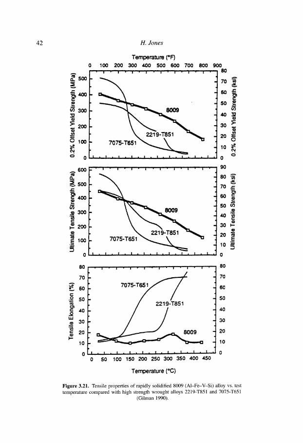
(3.7 MPa mm 1/2 compared with 2.3 MPa mm 1/2 for the wrought unalloyed condition). The new alloy chemistries afforded by rapid solidification have also led to improved ther- mal stability, such as in the A1-Fe-V-Si (8009) alloy developed by Allied Signal. Figure 3.21 (Gilman 1990) shows that 8009 retains relatively high strength in the range 150- 450~ where conventional wrought A1-Cu (2219) and A1-Zn-Mg-Cu (7075) lose most of their high ambient temperature strength as a result of precipitate coarsening. The re-
1200
1000 -
8O0 (3.
t - "
600
-o 400
200
0
: 1 i
O AI-Ni-Mm-Zr
(~ AI-Ni-Mm
[-] Fujila and Taba/a
/~ Wyrzykowski and Grabski
1 Hansen
Rapid Solidification 41
I I I t , , , [
20 40 60 80 100 120 140
d 1/2 / mm
Figure 3.20. Proof strength o-0. 2 vs. inverse square root of grain size d for rapidly solidified A1-Ni-Mn(-Zr) alloys ((30) compared with results for wrought unalloyed
aluminium ([]Am) (Nagahuma et al. 1993).
markable resistance to coarsening of the high volume fraction of the nanoscale silicide dispersoid in 8009 thus raises maximum service temperature by some 200 K. Creep resis- tance and corrosion resistance are also notably improved relative to established wrought ingot alloys of comparable room temperature strength. The limit on alloying set by in- cidence of unacceptable ingot macrosegregation in wrought ingot processing has been relaxed by rapid solidification processing for a number of other classes of material such as silicon irons for transformers, tool and bearing steels, nickel based superalloys and cop- per alloys for conductor applications. It is also a route of choice for processing the new class of high performance Nd-Fe-B permanent magnet materials based on the remarkable properties of the Nd2Fe14B compound.
3.4.2 Applications of rapid solidification
It is worth recalling that modem interest in rapid solidification processing stems from curiosity-driven research in the 1960s aimed at establishing its capabilities for generating new alloy phases (Duwez 1967) and size-refined microstructures (Grant 1970). There is no doubt that it has contributed much to our present understanding of what governs forma- tion of alloy phases, their mode of occurrence in solidification microstructures and their effect on properties and performance. It has also demonstrated the development potential of a number of previously underemployed production processes such as melt-atomization and spray forming, containerless processing, melt-spinning and thin-strip casting, and sur- face melt-traversing, all of which are undergoing intensive appraisal. A number of new
42 H. Jones
o,. 5OO
v
~,~oo q,) ta,,,.
W
cO 3OO
N. 200
~ 0
6O0 A
soo /rr
~' 4oo w
o~ 30O
cll I..- 2OO
t~ E lOO
o.,.., . . . , .
0
Tem~rature (*F) 0 100 200 300 400 500 600 700 800 900
" 7 0 ,,. 'K
80O9
2219-T851
- 7075-T651
8OO9
2219-T851 7075-T651
~ 9 ! r 1 i ! �9 1 �9 ! �9 1 . ! . ! i | �9 1_
c 50
co 40 N
t l l
3O ~: 113
�9 2 0 ~ O
. ~o ~
�9 0
9O
8O "~
70 .~
60 c
5O m
c ID
3O J--. o CD
2O N E
10 ----
0
8 0 "- I " ' �9 " ' " I " I " ' ' I ' " '" I " I - - " I[ "
70 -
-~ 6 o - - / c .~ s o �9
C:~ " l J
c ~0 - / j IJJ 30
V )
c: 20 ~
I-. 10
8 0
7O
7075-T651 60
5O 2219-T851
40
3O
8009 20
- 10
0 50 100 150 200 250 300 350 400 450
Temperature (*C)
Figure 3.21. Tensile properties of rapidly solidified 8009 (A1-Fe-V-Si) alloy vs. test temperature compared with high strength wrought alloys 2219-T851 and 7075-T651
(Gilman 1990).
R a p i d Sol id i f ica t ion 43
materials have been developed. These include a range of new soft (Smith 1993) and hard (Guthrie 1993) magnetic materials for application in power distribution as well as in mag- netic and electronic devices. New high performance light alloys have been established for both wear resistance (Amano et al. 1989) and high temperature (Gilman 1990) perfor- mance. Materials with enhanced catalytic performance (Hashimoto 1997) and for fuel cells (Kawashima et al. 1996) have been developed. Powder metallurgy tool steels and superalloys made from prealloyed atomized powder have an established market for in- serts, engineering parts and hard facings (Abraham 1991). Direct spray deposition has been employed to produce mill rolls with two or three times the life of conventionally produced rolls (Ikawa et al. 1990). Rapid solidification has been used to develop new al- loys for medical implants (Wang et al. 1988) and to make improved Ag-based feedstock particulate for producing dental amalgams (Vero et al. 1992). In addition rapid solidifi- cation has provided feedstocks for other developmental technologies such as mechanical alloying, plasma and high velocity spraying, and manufacture of metal matrix composites.
It has also provided cost-effective routes to make steel fibres for reinforcement of concrete and castable refractories (Edgington 1977) and aluminium flake for imparting conductivity to plastics (Holbrook 1986) as well as to form ductile brazing foils for a wide variety of precision joining applications (Rabinkin and Liebermann 1993). The newest ap- plication, that of a metallic glass golf club head (Ashley 1998) with strength and hardness twice that of cast stainless steel or titanium but of lower modulus and intermediate den- sity, made by bulk undercooling prior to solidification, would have been inconceivable 30 years ago.
REFERENCES
Abraham, T. (1991) Internat. J. Powder Metall., 27, 161. Alonso, J. A., Gallego, L. J. and Lopez, J. M. (1988) Phil. Mag., A58, 79. Amano, N., Odani, Y., Takeda, Y. and Akechi, K. (1989) Metal Powder Rept., 44, 186. Anderson, I. E. (1991) Adv. Mater. Process., 140(1), 30. Anon (1989) Adv. Mater. Process., 135(6), 12. Ashley, S. (1998) Mech. Eng., 120(6), 72. Boettinger, W. J. (1982) in Rapidly Quenched Metals, Vol. I, eds. Masumoto, T. and Suzuki, K. (The Japan
Institute of Metals, Sendai, Japan), p. 85. Boettinger, W. J., Shechtman, D., Schaefer, R. J. and Biancaniello, E S. (1984) Metall. Trans., A15, 55. Boettinger, W. J., Bendersky, L. A., Coriell, S. R., Schaefer, R. J. and Biancaniello, E S. (1987) J. Cryst. Growth,
80, 17. Boswell, E G. and Chadwick, G. A. (1977) Scripta Metall., 11, 459. Boulby, K. A. and Wood, J. V. (1986a) Powder Metall., 29, 33. Boulby, K. A. and Wood, J. V. (1986b) Metal Powder Rept., 41, 299. Davies, H. A., Aucote, J. and Hull, J. B. (1974) Scripta Metall., 8, 1179. Davis, L. A. (1976) in Rapidly Quenched Metals, eds. Grant, N. J. and Giessen, B. C. (MIT Press, Cambridge,
MA), p. 369. Duwez, P. (1967) Trans. Amer. Soc. Metals, 60, 607. Edgington, J. (1977) in Fibre-Reinforced Materials (Institute of Civil Engineers, London), p. 129. Feurer, U. and Wunderlin, R. (1977) DGM Fachbereicht, No. 38. Gelinas, C., Angers, R. and Pelletier, S. (1988) Mater. Lett., 6, 359. Gibeling, J. C. and Nix, W. D. (1978) Scripta Metall., 12, 919. Gilgien, E, Zryd, A. and Kurz, W. (1995) Acta Metall. Mater., 43, 3477. Gilman, E (1990) Metals and Materials, 6, 504. Grant, N. J. (1970) Fizika, 2 Suppl. 2, 16.1.
44 H. J o n e s
Greer, A. L. (1994) Nature, 368, 688. Guthrie, M. S. (1993) in Rapidly Solidified Alloys: Processes, Structures, Properties, Applications, ed.
Liebermann, H. H. (Marcel Dekker, New York), p. 665. Hashimoto, K. (1997) Mater. Sci. Eng. A, A226/228, 891. Herlach, D. M. (1994) Mater. Sci. Eng. Rept., R12, 177. Herlach, D. M., Gillesen, E, Volkmann, T., Wollgarten, M. and Urban, K. (1992) Phys. Rev. B, 46, 5203. Herlach, D. M., Cochrane, R. E, Egry, I., Fecht, H. J. and Greer, A. L. (1993) Internat. Mater. Rev., 38, 273. Holbrook, A. L. (1986) Internat. J. Powder Metall., 22, 39. Hunt, J. D. (1979) in Solidification and Casting of Metals (The Metals Society, London), p. 3. Hunt, J. D. and Lu, S.-Z. (1996) Metall. Trans. A, 27A, 611. Ikawa, Y., Itami, T., Kumagai, K., Kawashima, Y., Leatham, A. G., Coombs, J. S. and Brooks, R. G. (1990) ISIJ
Internat., 30, 756. Inoue, A., Zhang, T. and Masumoto, T. (1993) J. Non-Cryst. Solids, 156-158, 473. Jackson, K. A. and Hunt, J. D. (1966) Trans. Metall. Soc. AIME, 236, 1129. Johnson, W. L. (1996) Curr. Opin. Solid State & Mater. Sci., 1, 383. Johnson, W., Mamalis, A. G. and Hunt, H. (1976) Metallurgia and Metal Forming, 43(3), 68. Jones, H. (1984) J. Mater. Sci., 19, 1043. Jones, H. (1988) Mater. Lett., 6, 181. Jones, H. (1991) in Proceedings of the Second Japan International SAMPE Symposium, eds. Kimpara, I.,
Kageyama, K. and Kagawa, Y., SAMPE, p. 306. Juarez-Islas, J. A. and Jones, H. (1987) Acta Metall., 35, 499. Kawashima, A., Habazaki, H., Asami, K. and Hashimoto, K. (1996) Sci. Rept. RITU A, A42, 91. Kim, W. T. and Cantor, B. (1994) Acta Metall. Mater., 42, 3045. Kim, Y. H., Inoue, A. and Masumoto, T. (1990) Mater. Trans. JIM, 31,747. Kui, H. W., Greer, A. L. and Tumbull, D. (1984) Appl. Phys. Lett., 45, 615. Kurz, W. and Fisher, D. J. (1981) Acta Metall., 29, 11. Kurz, W., Giovanola, B. and Trivedi, R. (1986) Acta Metall., 34, 823. Kurz, W., Giovanola, B. and Trivedi, R. (1988) J. Cryst. Growth, 91, 123. Lu, S.-Z., Hunt, J. D., Gilgien, P. and Kurz, W. (1994) Acta Metall. Mater., 42, 1653. Lux, B. and Hiller, W. (1972) Praktische Metallographie, 8, 218. Maringer, R. E. and Mobley, C. E. (1974) J. Vac. Sci. Technol., 11, 1067. Massalski, T. B., Kim, Y. W., Vassamillet, L. E and Hopper, R. W. (1981) Mater. Sci. Eng., 47, 1. Midson, S. E and Jones, H. (1982) in Rapidly Quenched Metals, Vol. II, eds. Masumoto, T. and Suzuki, K. (The
Japan Institute of Metals, Sendai, Japan), p. 1539. Moir, S. A. and Jones, H. (1991) Mater. Lett., 12, 141. Nagahuma, H., Ohtera, K., Higashi, K., Inoue, A. and Masumoto, T. (1993) Phil. Mag. Lett., 67, 225. Oguchi, M., Inoue, A., Yamaguchi, H. and Masumoto, T. (1990) Mater. Trans. JIM, 31, 1005. Ohnaka, I. (1985) Internat. J. Rapid Solidification, 1, 219. Overshott, K. J. (1979) Electron. Power, 25, 347. Peker, A. and Johnson, W. L. (1993) Appl. Phys. Lett., 63, 2342. Pelletier, S., Gelinas, C. and Angers, R. (1990) lnternat. J. Powder Metall., 26, 51. Perepezko, J. H. (1984) Mater. Sci. Eng., 65, 125. Prasad, Y. V. S. S., Ramachandrarao, E and Chattopadhyay, K. (1984) Acta Metall., 32, 1825. Rabinkin, A. and Liebermann, H. H. (1993) in Rapidly Solidified Alloys: Processes, Structures, Properties,
Applications, ed. Liebermann, H. H. (Marcel Dekker, New York), p. 691. Raman, R. V., Patel, A. N. and Carbonara, R. S. (1982) Prog. Powder Metall., 38, 99. Rama Rao, E and Radhakrishnan, V. M. (1984) in Metallic Glasses, ed. Anantharaman, T. R. (TransTech,
Aedermannsdorf, Switzerland), p. 225. Schmitt, H. (1979) Powder Met. Internat., 11, 17. Smith, C. H. (1993) in Rapidly Solidified Alloys: Processes, Structures, Properties, Applications, ed. Lieber-
mann, H. H. (Marcel Dekker, New York), p. 617. Spaepen, E (1987) in Undercooled Alloy Phases, eds. Collings, E. W. and Koch, C. C. (TMS, Warrendale, PA),
p. 187. Vero, B., Fauszt, A., Tardy, E, Takacs, J., Konczos, G. and Lovas, T. (1992) Mater. Sci. Technol., 8, 645. von Allmen, M., Huber, M., Blatter, A. and Affolter, K. (1984) Internat. J. Rapid Solidification, 1, 15. Wang, K. K., Gustavson, L. J. and Dumbleton, J. H. (1988) Mod. Dev. Powder Metall., 20, 361.
Rap id Solidi f ication 45
Weber, J. K. R., Krishnan, S. and Nordine, R C. (1991) J. Metals, 43(7), 8. Zimmermann, M., Carrard, M. and Kurz, W. (1989) Acta Metall., 32, 3305.
SELECTED B I B L I O G R A P H Y
Ananthararman, T. R. (ed.) (1984) Metallic Glasses, Production, Properties and Applications (TransTech, Aedermannsdorf, Switzerland), 300 pp.
Anantharaman, T. R. and Suryanarayana, C. (1987) Rapidly Solidified Metals (TransTech, Aedermannsdorf, Switzerland), 260 pp.
Cahn, R. W. and Greer, A. L. (1996) in Physical Metallurgy, eds. Cahn, R.W. and Haasen, P., fourth edition (Elsevier Science, Oxford), p. 1723.
Gilman, J. J. and Leamy, H. J. (1978) Metallic Glasses (American Society for Metals, Metals Park, OH), 350
PP. G~intherodt, H. J. and Beck, H. (1981) Glassy Metals I (Springer-Verlag, Berlin), 270 pp. Gtintherodt, H. J. and Beck, H. (1983) Glassy Metals II (Springer, Berlin, Germany), 400 pp. Herman, H. (ed.) (1981) Ultrarapid Quenching of Metals and Alloys (Academic Press, New York), 448 pp. Jacobson, L. A. and McKittnick, J. (1994) Mater. Sci. Eng. R, R l l , 355. Jones, H. (1982) Rapid Solidification of Metals and Alloys (Institution of Metallurgists, London), 83 pp. Jones, H. (1984) J. Mater. Sci., 19, 1043. Jones, H. (1991) Metals and Materials, 7, 486. Liebermann, H. H. (ed.) (1993) Rapidly Solidified Alloys: Processes, Structures, Properties, Applications
(Marcel Dekker, New York), 808 pp. Luborsky, E E. (ed.) (1983) Amorphous Metallic Alloys (Butterworths, Stoneham, MA), 548 pp. Otooni, M. A. (ed.) (1997) Elements of Rapid Solidification (Springer-Verlag, Berlin), 320 pp. Sahm, P. R., Jones, H. and Adam, C. M. (eds.) (1986) Science and Technology ofthe Undercooled Melt (Martinus
Nijhoff, Dordrecht, The Netherlands), 304 pp. Srivatsan, T. S. and Sudarshan, T. S. (1993) Rapid Solidification Technology: An Engineering Guide (Techno-
matic., Lancaster, PA), 737 pp.
These volumes provide extensive reviews of their subject areas that were comprehensive at the time of their compilation. More specialized review articles also continue to appear but are too numerous to list here. In addition, the series of international conferences that began in Brela, Yugoslavia, in 1970 and reached its ninth at Bratislava in 1996 and the tenth in Bangalore, India in 1999 contain numerous useful review articles within their Proceedings (for the ninth conference see Mater. Sci. Eng. A, 15th June 1997 issue, Vols. A 226-228, 1110 pp). The proceedings of two recent NATO workshops are also useful: Undercooled Metallic Melts: Properties, Solidification and Metastable Phases, eds. D. M Herlach et al., Mater. Sci. Eng. A, 1994, A178(1,2), 320 pp, and Science and Technology of Rapid Solidification and Processing, ed. M. A Otooni, Kluwer, Dordrecht, 1995, 390 pp). International Journal of Rapid Solidification, Vol. 1, No. 1 (1984) to Vol. 9, No. 4 (1996), is the only journal dedicated to publication of research papers in the field. It continues with its new name International Journal of Nonequilibrium Processing with Vol. 10, No. 1 in 1997.