Technical Standards for Federal Non-Licensed … Standards for Federal "Non-Licensed" Devices ......
42
K-1 1/2008 K.1 K ANNEX K Technical Standards for Federal "Non-Licensed" Devices K.1 INTRODUCTION This Annex sets out the Federal Government regulations and technical specifications under which a low power intentional, unintentional or incidental radiator or device may be developed and operated officially by a Federal Government Agency without an NTIA approved frequency assignment as described in Section 7.9 of this Manual. Non-Federal operations of these radiators, called non-licensed devices or Part 15 devices, are regulated by the Federal Communications Commission (FCC) Code of Federal Government Regulations, Title 47, Part 15. FCC regulations and standards do not apply to the Federal Government although many low power devices are operated by the Agencies without an NTIA approved frequency assignment. The NTIA thus provides the regulations and standards in this Annex for regulating Federal Government official development of low power radiators as non-licensed devices. The regulations and standards in this Annex are a subset of the FCC Part 15 regulations. The IRAC/TSC will continue to maintain an awareness of FCC changes to the Part 15 rules and, where appropriate, incorporate such changes in this Annex. A "Cross Reference" of the regulations in this Annex and those in the FCC CFR 47, Part 15 regulations is given at the end of this Annex. K.1.1 DEFINITIONS Auditory Assistance Device: An intentional radiator used to provide auditory assistance to a handicapped person or persons. Such a device may be used for auricular training in an educational institution, for auditory assistance at places of public gatherings, such as a church, theater, or auditorium, and for auditory assistance to handicapped individuals, only, in other locations. Biomedical Telemetry Device: An intentional radiator used to transmit measurements of either human or animal biomedical phenomena to a receiver. Carrier Current System: A system that transmits radio frequency energy by conduction over the electric power lines. A carrier current system can be designed such that the signals are received by conduction directly from connection to the electric power lines (unintentional radiator) or the signals are received over-the-air due to radiation of the radio frequency signals from the electric power lines (intentional radiator). Class A Digital Device: A digital device that is for use in a commercial, industrial or business environment, exclusive of a device which is for use by the general public or is intended to be used in the home. Class B Digital Device: A digital device that is for use in a residential environment notwithstanding use in commercial, business or industrial environments. Examples of such devices include, but are not limited to, personal computers, calculators, and similar electronic devices that are marketed for use by the general public. NOTE: The responsible party may also qualify a device intended to be in a commercial, business or industrial environment as a Class B device, and in fact is encouraged to do so, provided the device complies with the technical specifications for a Class B digital device. In the event that a particular type of device has been found to repeatedly cause harmful interference to radio communications, the Commission may classify such a digital device as a Class B digital device, regardless of its intended use.
Transcript of Technical Standards for Federal Non-Licensed … Standards for Federal "Non-Licensed" Devices ......
K-1 1/2008 K.1
K ANNEX K Technical Standards for Federal "Non-Licensed" Devices
K.1 INTRODUCTION
This Annex sets out the Federal Government regulations and technical specifications under which a low power intentional, unintentional or incidental radiator or device may be developed and operated officially by a Federal Government Agency without an NTIA approved frequency assignment as described in Section 7.9 of this Manual. Non-Federal operations of these radiators, called non-licensed devices or Part 15 devices, are regulated by the Federal Communications Commission (FCC) Code of Federal Government Regulations, Title 47, Part 15. FCC regulations and standards do not apply to the Federal Government although many low power devices are operated by the Agencies without an NTIA approved frequency assignment. The NTIA thus provides the regulations and standards in this Annex for regulating Federal Government official development of low power radiators as non-licensed devices. The regulations and standards in this Annex are a subset of the FCC Part 15 regulations. The IRAC/TSC will continue to maintain an awareness of FCC changes to the Part 15 rules and, where appropriate, incorporate such changes in this Annex.
A "Cross Reference" of the regulations in this Annex and those in the FCC CFR 47, Part 15 regulations is given at the end of this Annex.
K.1.1 DEFINITIONS
Auditory Assistance Device: An intentional radiator used to provide auditory assistance to a handicapped person or persons. Such a device may be used for auricular training in an educational institution, for auditory assistance at places of public gatherings, such as a church, theater, or auditorium, and for auditory assistance to handicapped individuals, only, in other locations.
Biomedical Telemetry Device: An intentional radiator used to transmit measurements of either human or animal biomedical phenomena to a receiver.
Carrier Current System: A system that transmits radio frequency energy by conduction over the electric power lines. A carrier current system can be designed such that the signals are received by conduction directly from connection to the electric power lines (unintentional radiator) or the signals are received over-the-air due to radiation of the radio frequency signals from the electric power lines (intentional radiator).
Class A Digital Device: A digital device that is for use in a commercial, industrial or business environment, exclusive of a device which is for use by the general public or is intended to be used in the home.
Class B Digital Device: A digital device that is for use in a residential environment notwithstanding use in commercial, business or industrial environments. Examples of such devices include, but are not limited to, personal computers, calculators, and similar electronic devices that are marketed for use by the general public. NOTE: The responsible party may also qualify a device intended to be in a commercial, business or industrial environment as a Class B device, and in fact is encouraged to do so, provided the device complies with the technical specifications for a Class B digital device. In the event that a particular type of device has been found to repeatedly cause harmful interference to radio communications, the Commission may classify such a digital device as a Class B digital device, regardless of its intended use.
K-2 1/2008K.1.1
Cordless Telephone System: A system consisting of two transceivers, one a base station that connects to the public switched telephone network and the other a mobile handset unit that communicates directly with the base station. Transmissions from the mobile unit are received by the base station and then placed on the public switched telephone network. Information received from the switched telephone network is transmitted by the base station to the mobile unit.
NOTE: The Domestic Public Cellular Radio Telecommunications Service is considered to be part of the switched telephone network. In addition, intercom and paging operations are permitted provided these are not intended to be the primary modes of operation.
Digital Device (previously defined as a computing device): An unintentional radiator (device or
system) that generates and uses timing signals or pulses at a rate in excess of 9,000 pulses (cycles) per second and uses digital techniques; inclusive of telephone equipment that uses digital techniques or any device or system that generates and uses radio frequency energy for the purpose of performing data processing functions, such as electronic computations, operations, transformations, recording, filing, sorting, storage, retrieval, or transfer. A radio frequency device that is specifically subject to an emanation requirement in any other part or section of the NTIA Manual or an intentional radiator subject to Section K.3 of this Annex that contains a digital device is not subject to the standards for digital devices, provided the digital device is used only to enable operation of the radio frequency device and the digital device does not control additional functions or capabilities.
NOTE: Computer terminals and peripherals that are intended to be connected to a computer are digital devices.
External Radio Frequency Power Amplifier: A device which is not an integral part of an
intentional radiator as manufactured and which, when used in conjunction with an intentional radiator as a signal source, is capable of amplifying that signal.
Direct Sequence Systems: A spread spectrum system in which the carrier has been modulated by a high speed spreading code and an information data stream. The high speed code sequence dominates the "modulation function" and is the direct cause of the wide spreading of the transmitted signal.
Field Disturbance Sensor: A device that establishes a radio frequency field in its vicinity and detects changes in that field resulting from the movement of persons or objects within its range.
Frequency Hopping Systems: A spread spectrum system in which the carrier is modulated with the coded information in a conventional manner causing a conventional spreading of the RF energy about the frequency carrier. The Frequency of the carrier is not fixed but changes at fixed intervals under the direction of a coded sequence. The wide RF bandwidth needed by such a system is not required by spreading of the RF energy about the carrier but rather to accommodate the range of frequencies to which the carrier frequency can hop. A frequency hopping system should select operating frequencies from among those in the hop set such that all frequencies are used with equal probability, and all frequency transitions are equally probable.
Hop Set: The set of all frequencies upon which a frequency hopping transmitter may operate. Incidental Radiator: A device that generates radio frequency energy during the course of its
operation although the device is not intentionally designed to generate or emit radio frequency energy. Examples of incidental radiators are DC motors, mechanical light switches, etc.
Intentional Radiator: A device that intentionally generates and emits radio frequency energy by radiation or induction.
Perimeter Protection System: A field disturbance sensor that employs RF transmission lines as the radiating source. These RF transmission line are installed in such a manner that allows the system to detect movement within the protected area.

K-3 1/2008 K.1.1
Unintentional Radiator: A device that intentionally generates radio frequency energy for use within the device, or that sends radio frequency signals by conduction to associated equipment via connecting wiring, but which is not intended to emit RF energy by radiation or induction.
Ultrawideband system/device: A system or device or field disturbance sensor that intentionally radiates over a bandwidth of not less than 500 MHz as further described under Section K.3.6 of this Annex.
K.1.2 INCIDENTAL RADIATORS1
Manufacturers of these devices shall employ good engineering practices to minimize the risk of harmful interference.
An intentional or unintentional radiator shall be constructed in accordance with good engineering design and manufacturing practice. Emanations from the device shall be suppressed as much as practicable, but in no case shall the emanations exceed the levels specified in these rules.
An intentional or unintentional radiator must be constructed such that the adjustments of any control that is readily accessible by or intended to be accessible to the user will not cause operation of the device in violation of the regulations.
K.1.3 SUSCEPTIBILITY TO INTERFERENCE
Agencies responsible for equipment compliance are advised to consider the proximity and the high power of non-Federal licensed radio stations, such as broadcast, amateur, land mobile, and non-geostationary mobile satellite feeder link earth stations, and of U.S. Government radio stations, which could include high-powered radar systems, when choosing operating frequencies during the design and acquisition of their equipment so as to reduce the susceptibility for receiving harmful interference.
K.1.4 LABELING REQUIREMENTS
Federal agencies should insure that non-licensed devices purchased under the provisions of Section 7.8 of this manual have the appropriate FCC label affixed.
Federal agencies should insure that non-licensed devices developed under the provisions of Section 7.9 and Annex K should have a reference to Section 7.9 and Annex K in the appropriate training and/or operations manual or other documentation.
K.1.5 EMISSION LIMITS
The conducted and radiated emission limits shown in this part are based on the following, unless otherwise specified:
a. On any frequency or frequencies below or equal to 1000 MHz, the limits shown are based on measuring equipment employing a CISPR quasi-peak detector function and related measurement bandwidths, unless otherwise specified. The specifications for the measuring instrument using the CISPR quasi-peak detector can be found in Publication 16 of the International Special Committee on Radio Interference (CISPR) of the International Electrotechnical Commission. As an alternative to CISPR quasi-peak measurements, the responsible party, at its option, may demonstrate compliance with the emission limits using measuring equipment employing a peak detector function, properly adjusted for such factors as pulse desensitization, as long as the same bandwidths as indicated for CISPR quasi-peak measurements are employed.
1 This section includes text from CFR 47 Parts 13 and 15.

K-4 1/2008K.1.5
NOTE: For pulse modulated devices with a pulse-repetition frequency of 20 Hz or less and for which CISPR quasi-peak measurements are specified, compliance with the regulations shall be demonstrated using measuring equipment employing a peak detector function, properly adjusted for such factors as pulse desensitization, using the same measurement bandwidths that are indicated for CISPR quasi-peak measurements.
b. On any frequency or frequencies above 1000 MHz, the radiated limits shown are based on the
use of measurement instrumentation employing an average detector function. When average radiated emission measurements are specified in the regulations, including emission measurements below 1000 MHz, there is also a limit on the radio frequency emissions, as measured using instrumentation with a peak detector function, corresponding to 20 dB above the maximum permitted average limit for the frequency being investigated. Measurements of AC power line conducted emissions are performed using a CISPR quasi-peak detector, even for devices for which average radiated emission measurements are specified.
c. When the radiated emission limits are expressed in terms of the average value of the emission, and pulsed operation is employed, the measured field strength shall be determined by averaging over one complete pulse train, including blanking intervals, as long as the pulse train does not exceed 0.1 seconds. As an alternative (provided the transmitter operates for longer than 0.1 seconds) or in those cases where the pulse train exceeds 0.1 seconds, the measured field strength shall be determined from the average absolute voltage during a 0.1 second interval during which the field strength is at its maximum value. The exact method of calculating the average field strength shall be submitted with any application for certification or shall be retained in the measurement data file for equipment subject to notification or verification.
K.1.6 Frequency Range and Distance Extrapolation of Radiated Measurements
1. Unless otherwise noted in the specific section in this Annex under which the equipment operates for an intentional radiator the spectrum shall be investigated from the lowest radio frequency signal generated in the device, without going below 9 kHz, up to at least the frequency shown in this paragraph:
a. If the intentional radiator operates below 10 GHz: to the tenth harmonic of the highest fundamental frequency or to 40 GHz, whichever is lower.
b. If the intentional radiator operates at or above 10 GHz and below 30 GHz: to the fifth harmonic of the highest fundamental frequency or to 100 GHz, whichever is lower.
c. If the intentional radiator operates at or above 30 GHz: to the fifth harmonic of the highest fundamental frequency or to 200 GHz, whichever is lower, unless specified otherwise elsewhere
in the rules. d. If the intentional radiator contains a digital device, regardless of whether this digital device
controls the functions of the intentional radiator or the digital device is used for additional control or function purposes other than to enable the operation of the intentional radiator, the frequency range shall be investigated up to the range specified in paragraphs (a)(1)-(a)(3) of this section or the range applicable to the digital device, as shown in paragraph (b)(1) of this section, whichever is the higher frequency range of investigation.
2 For unintentional radiators: a. Except as otherwise indicated in paragraphs (b)(2) or (b)(3), for an unintentional radiator,
including a digital device, the spectrum shall be investigated from the lowest radio frequency signal generated or used in the device, without going below the lowest frequency for which a radiated emission limit is specified, up to the frequency shown in the following table:
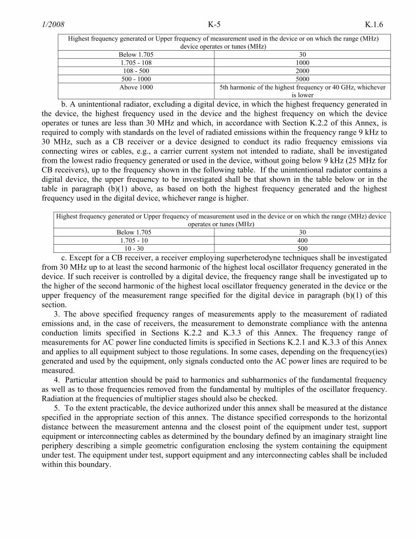
K-5 1/2008 K.1.6
Highest frequency generated or Upper frequency of measurement used in the device or on which the range (MHz) device operates or tunes (MHz)
Below 1.705 30 1.705 - 108 1000 108 - 500 2000
500 - 1000 5000 Above 1000 5th harmonic of the highest frequency or 40 GHz, whichever
is lower b. A unintentional radiator, excluding a digital device, in which the highest frequency generated in
the device, the highest frequency used in the device and the highest frequency on which the device operates or tunes are less than 30 MHz and which, in accordance with Section K.2.2 of this Annex, is required to comply with standards on the level of radiated emissions within the frequency range 9 kHz to 30 MHz, such as a CB receiver or a device designed to conduct its radio frequency emissions via connecting wires or cables, e.g., a carrier current system not intended to radiate, shall be investigated from the lowest radio frequency generated or used in the device, without going below 9 kHz (25 MHz for CB receivers), up to the frequency shown in the following table. If the unintentional radiator contains a digital device, the upper frequency to be investigated shall be that shown in the table below or in the table in paragraph (b)(1) above, as based on both the highest frequency generated and the highest frequency used in the digital device, whichever range is higher.
Highest frequency generated or Upper frequency of measurement used in the device or on which the range (MHz) device
operates or tunes (MHz) Below 1.705 30
1.705 - 10 400 10 - 30 500
c. Except for a CB receiver, a receiver employing superheterodyne techniques shall be investigated from 30 MHz up to at least the second harmonic of the highest local oscillator frequency generated in the device. If such receiver is controlled by a digital device, the frequency range shall be investigated up to the higher of the second harmonic of the highest local oscillator frequency generated in the device or the upper frequency of the measurement range specified for the digital device in paragraph (b)(1) of this section.
3. The above specified frequency ranges of measurements apply to the measurement of radiated emissions and, in the case of receivers, the measurement to demonstrate compliance with the antenna conduction limits specified in Sections K.2.2 and K.3.3 of this Annex. The frequency range of measurements for AC power line conducted limits is specified in Sections K.2.1 and K.3.3 of this Annex and applies to all equipment subject to those regulations. In some cases, depending on the frequency(ies) generated and used by the equipment, only signals conducted onto the AC power lines are required to be measured.
4. Particular attention should be paid to harmonics and subharmonics of the fundamental frequency as well as to those frequencies removed from the fundamental by multiples of the oscillator frequency. Radiation at the frequencies of multiplier stages should also be checked.
5. To the extent practicable, the device authorized under this annex shall be measured at the distance specified in the appropriate section of this annex. The distance specified corresponds to the horizontal distance between the measurement antenna and the closest point of the equipment under test, support equipment or interconnecting cables as determined by the boundary defined by an imaginary straight line periphery describing a simple geometric configuration enclosing the system containing the equipment under test. The equipment under test, support equipment and any interconnecting cables shall be included within this boundary.
K-6 1/2008K.1.6
a. At frequencies at or above 30 MHz, measurements may be performed at a distance other than what is specified provided: measurements are not made in the near field except where it can be shown that near field measurements are appropriate due to the characteristics of the device; and it can be demonstrated that the signal levels needed to be measured at the distance employed can be detected by the measurement equipment. Measurements shall not be performed at a distance greater than 30 meters unless it can be further demonstrated that measurements at a distance of 30 meters or less are impractical. When performing measurements at a distance other than that specified, the results shall be extrapolated to the specified distance using an extrapolation factor of 20 dB/decade (inverse linear-distance for field strength measurements; inverse-linear-distance-squared for power density measurements).
b. At frequencies below 30 MHz, measurements may be performed at a distance closer than that specified in the regulations; however, an attempt should be made to avoid making measurements in the near field. Pending the development of an appropriate measurement procedure for measurements performed below 30 MHz, when performing measurements at a closer distance than specified, the results shall be extrapolated to the specified distance by either making measurements at a minimum of two distances on at least one radial to determine the proper extrapolation factor or by using the square of an inverse linear distance extrapolation factor (40 dB/decade).
c. The extrapolation method used in the device certification will be specified. d. When measurement distances of 30 meters or less are specified, the equipment will be measured
at the distance specified unless measurement at that distance results in measurements being performed in the near field. When measurement distances of greater than 30 meters are specified in the regulations, the equipment can be tested at a closer distance, usually 30 meters, extrapolating the measured field strength to the specified distance using the methods shown in this section.
K.2 UNINTENTIONAL RADIATORS
K.2.1 CONDUCTED LIMITS
1. Except for Class A digital devices, for equipment that is designed to be connected to the public utility (AC) power line, the radio frequency voltage that is conducted back onto the AC power line on any frequency or frequencies within the band 450 kHz to 30 MHz shall not exceed 250 microvolts. Compliance with this provision shall be based on the measurement of the radio frequency voltage between each power line and ground at the power terminals.
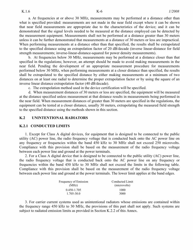
2. For a Class A digital device that is designed to be connected to the public utility (AC) power line, the radio frequency voltage that is conducted back onto the AC power line on any frequency or frequencies within the band 450 kHz to 30 MHz shall not exceed the limits in the following table. Compliance with this provision shall be based on the measurement of the radio frequency voltage between each power line and ground at the power terminals. The lower limit applies at the band edges.
Frequency of Emission
(MHz) Conducted Limit
(microvolts) 0.450-1.705 1000 1.705-30.0 3000
3. For carrier current systems used as unintentional radiators whose emissions are contained within
the frequency range 450 kHz to 30 MHz, the provisions of this part shall not apply. Such systems are subject to radiated emission limits as provided in Section K.2.2 of this Annex.
K-7 1/2008 K.2.1
4. Measurements to demonstrate compliance with the conducted limits are not required for devices which only employ battery power for operation and which do not operate from the AC power lines or contain provisions for operation while connected to the AC power lines. Devices that include, or make provision for, the use of AC adaptors or battery eliminators or that connect to the AC power line indirectly, obtaining their power through another device which is connected to the AC power lines, shall be tested to demonstrate compliance with the conducted limits.
K.2.2 RADIATED EMISSION LIMITS
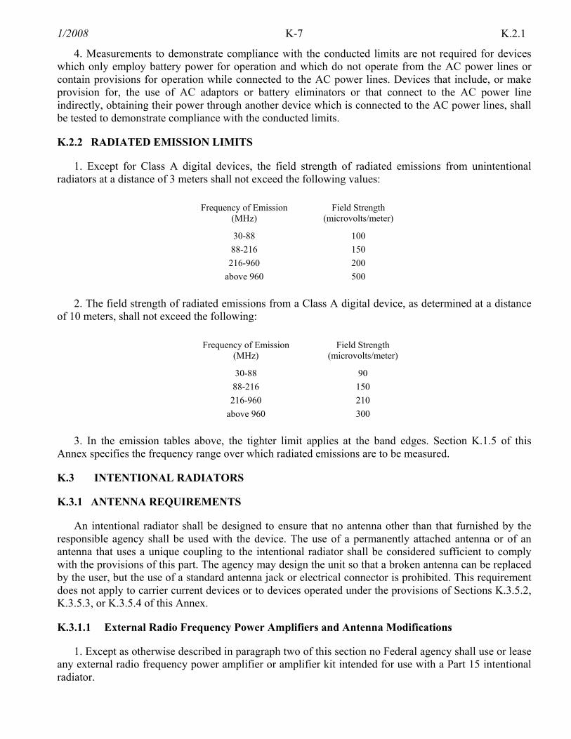
1. Except for Class A digital devices, the field strength of radiated emissions from unintentional radiators at a distance of 3 meters shall not exceed the following values:
Frequency of Emission
(MHz) Field Strength
(microvolts/meter)
30-88 100 88-216 150 216-960 200
above 960 500
2. The field strength of radiated emissions from a Class A digital device, as determined at a distance of 10 meters, shall not exceed the following:
Frequency of Emission
(MHz) Field Strength
(microvolts/meter)
30-88 90 88-216 150
216-960 210 above 960 300
3. In the emission tables above, the tighter limit applies at the band edges. Section K.1.5 of this
Annex specifies the frequency range over which radiated emissions are to be measured.
K.3 INTENTIONAL RADIATORS
K.3.1 ANTENNA REQUIREMENTS
An intentional radiator shall be designed to ensure that no antenna other than that furnished by the responsible agency shall be used with the device. The use of a permanently attached antenna or of an antenna that uses a unique coupling to the intentional radiator shall be considered sufficient to comply with the provisions of this part. The agency may design the unit so that a broken antenna can be replaced by the user, but the use of a standard antenna jack or electrical connector is prohibited. This requirement does not apply to carrier current devices or to devices operated under the provisions of Sections K.3.5.2, K.3.5.3, or K.3.5.4 of this Annex.
K.3.1.1 External Radio Frequency Power Amplifiers and Antenna Modifications
1. Except as otherwise described in paragraph two of this section no Federal agency shall use or lease any external radio frequency power amplifier or amplifier kit intended for use with a Part 15 intentional radiator.

K-8 1/2008K.3.1
2. A transmission system consisting of an intentional radiator, an external radio frequency power amplifier, and an antenna, may be authorized for use under this section. However, when a transmission system is authorized as a system, it must always be used as a complete system and must always be used in the configuration in which it was authorized. An external radio frequency power amplifier shall be used only in the system configuration with which the amplifier is authorized and shall not be used as a separate product.
3. Only the antenna with which an intentional radiator is authorized may be used with the intentional radiator.
K.3.2 RESTRICTED BANDS OF OPERATION
1. Except as specified in paragraph 5 of this section, only spurious emissions are permitted in any of the frequency bands listed below:
MHz MHz MHz GHz 0.090-0.110 16.42-16.423 399.9-410 4.5-5.15 0.495-0.505 16.69475-16.69525 608-614 5.35-5.46 2.1735-2.1905 16.80425-16.80475 960-1240 7.25-7.75 4.125-4.128 25.5-25.67 1300-1427 8.025-8.5 4.17725-4.17775 37.5-38.25 1435-1626.5 9.0-9.2 4.20725-4.20775 73-74.6 1645.5-1646.5 9.3-9.5 6.215-6.218 74.8-75.2 1660-1710 10.6-12.7 6.26775-6.26825 108-121.94 1718.8-1722.2 13.25-13.4 6.31175-6.31225 123-138 2200-2300 14.47-14.5 8.291-8.294 149.9-150.05 2310-2390 15.35-16.2 8.362-8.366 156.52475-156.52525 2483.5-2500 17.7-21.4 8.37625-8.38675 156.7-156.9 2655-2900 22.01-23.12 8.41425-8.41475 162.0125-167.17 3260-3267 23.6-24.0 12.29-12.293 167.72-173.2 3332-3339 31.2-31.8 12.51975-12.52025 240-285 3345.8-3358 36.43-36.5 12.57675-12.57725 322-335.4 3600-4400 Above 38.6 13.36-13.41
2. The table below identifies how each of the restricted bands, as identified above, are used.
Restricted Bands by Use Band (MHz) Allocation/Use 0.090-0.110 Loran C radionavigation 0.495-0.505 Maritime distress frequency 2.1735-2.1905 Mobile distress frequency 4.125-4.128 Global Maritime Distress and Safety System 4.17725-4.17775 Global Maritime Distress and Safety System 4.20725-4.20775 Global Maritime Distress and Safety System 6.215-6.218 Global Maritime Distress and Safety System 6.26775-6.26825 Global Maritime Distress and Safety System 6.31175-6.31225 Global Maritime Distress and Safety System 8.291-8.294 Global Maritime Distress and Safety System 8.362-8.366 Maritime & aeronautical survival craft search and rescue 8.37625-8.38675 Global Maritime Distress and Safety System 8.41425-8.41475 Global Maritime Distress and Safety System 12.29-12.293 Global Maritime Distress and Safety System 12.51975-12.52025 Global Maritime Distress and Safety System 12.57675-12.57725 Global Maritime Distress and Safety System 13.36-13.41 Radio astronomy 16.42-16.423 Global Maritime Distress and Safety System 16.69475-16.69525 Global Maritime Distress and Safety System 16.80425-16.80475 Global Maritime Distress and Safety System 25.5-25.67 Radio astronomy

K-9 1/2008 K.3.2
Restricted Bands by Use Band (MHz) Allocation/Use 37.5-38.25 Radio astronomy 73-75.2 73-74.6 MHz: radio astronomy,
74.8-75.2 MHz: aeronautical radionavigation marker beacon (75 MHz) and guard bands 108-121.94 108-117.975 MHz: aeronautical radionavigation (aircraft-to-tower),
117.975-121.9375 MHz: aeronautical mobile for safety and regularity of flight, 121.4-121.6 MHz: search and rescue (SARSAT)
123-138 123-123.2 MHz: coordinated search and rescue by mobile, land and aeronautical, 123.2-123.8 MHz: aeronautical flight test voice communications, 123.5875-137 MHz: aeronautical mobile for safety and regularity of flight 137-138 MHz: satellite down link
149.9-150.05 Radionavigation satellite down link 156.52475-156.52525 Global Maritime Distress and Safety System 156.7-156.9 Search and rescue (maritime mobile distress and calling on 156.7625-156.8375 MHz) 162.0125-167.17 167.72-173.2
Wind shear detection around airports and to warn pilots when emergency action is needed, protection of national and visiting foreign dignitaries, and tracking of endangered and dangerous wildlife, law enforcement
240-285 243 MHz (SARSAT), satellite down links, military satellites, glide slope indicators, instrument landing systems
322-335.4 322-328.6 MHz: radio astronomy, 328.6-335.4 MHz: aeronautical radionavigation-instrument landing systems
399.9-410 399.9-400.05 MHz: radionavigation satellite, 400.05-400.15 MHz: standard frequency and time signal, 400.15-402 MHz: satellite down links, 402-406 MHz: meteorological aids (radiosondes), 406-406.1 MHz: emergency position-indicating radiobeacon (EPIRB), 406.1-410 MHz: radio astronomy
608-614 Radio astronomy 960-1240 960-1215 MHz: aeronautical radionavigation,
1215-1240 MHz: satellite down link 1300-1427 1300-1350 MHz: aeronautical radionavigation,
1350-1400 MHz: spectral line observation of neutral hydrogen, 1400-1427 MHz: radio astronomy
1435-1626.5 1435-1525 MHz: aeronautical flight test telemetry, 1525-1559 MHz: satellite down links, 1559-1610 MHz: radionavigation satellite down link (GPS) and aeronautical radionavigation, 1610-1626.5 MHz: aeronautical radionavigation, 1610.6-1613.8 MHz: spectral line observation
1645.5-1646.5 Global Maritime Distress and Safety System 1660-1710 1660-1668.4 MHz: radio astronomy,
1668.4-1670 MHz: radio astronomy and radiosonde, 1670-1710 MHz: satellite down link and radiosonde
1718.8-1722.2 Radio astronomy 2200-2300 Satellite down link 2310-2390 Aeronautical flight test telemetry 2483.5-2500 Radiodetermination satellite down link (Geostar) 2655-2900 2655-2690 MHz: radio astronomy and satellite down link,
2690-2700 MHz: radio astronomy, 2700-2900 MHz: air traffic control radars
3260-3267 Spectral line observations (radio astronomy) 3332-3339 Spectral line observations (radio astronomy) 3345.8-3358 Spectral line observation (radio astronomy) 3600-4400 3600-4200 MHz: satellite down link,
4200-4400 MHz: aeronautical radionavigation 4500-5150 4500-4800 MHz: satellite down link,
4800-5000 MHz: radio astronomy, 5000-5150 MHz: aeronautical radionavigation
5350-5460 Aeronautical radionavigation

K-10 1/2008K.3.1
Restricted Bands by Use Band (MHz) Allocation/Use 7250-7750 Satellite down link 8025-8500 Satellite down link 9000-9200 Aeronautical radionavigation 9300-9500 Radar transponders for maritime search and rescue, airborne weather and ground mapping
radar for airborne radionavigation 10600-12700 10600-10700 MHz: radio astronomy,
10700-12200 MHz: satellite down link, 12200-12700 MHz: direct broadcast satellite
13250-13400 Aeronautical radionavigation 14470-14500 Spectral line observation (radio astronomy) 15350-16200 15350-15400 MHz: radio astronomy,
15400-15700 MHz: shuttle landing system, airborne weather and ground mapping radar for radionavigation, 15700-16200 MHz: airport surface detection equipment used to locate and navigate aircraft while on the ground
17700-21400 Satellite down link 22010-23120 22010-22500 MHz: radio astronomy,
22500-23000 MHz: broadcast satellite and radio astronomy, 23000-23070 MHz: fixed/inter-satellite/mobile, 23070-23120 MHz: radio astronomy
23600-24000 Radio astronomy 31200-31800 Radio astronomy 36430-36500 Radio astronomy Above 38600 Satellite down link, Radio astronomy
3. Except as specified in paragraphs 5 and 6, the field strength of emissions appearing within these
frequency bands shall not exceed the limits shown in Section K.3.4 of this Annex. At frequencies equal to or less than 1000 MHz, compliance with the limits in Section K.3.4 of this Annex shall be demonstrated using measurement instrumentation employing a CISPR quasi-peak detector. Above 1000 MHz, compliance with the emission limits in Section K.3.4 of this Annex shall be demonstrated based on the average value of the measured emissions. The provisions in Section K.1.5 of this Annex apply to these measurements.
4. Except as specified in paragraphs 5 and 6 of this section, regardless of the field strength limits specified elsewhere in this Annex, the provisions of this part apply to emissions from any intentional radiator.
5. The following devices are exempt from the requirements of this part: a. Swept frequency field disturbance sensors operating between 1.705 and 37 MHz provided their
emissions only sweep through the bands listed in paragraph 1, the sweep is never stopped with the fundamental emission within the bands listed in paragraph 1, and the fundamental emission is outside of the bands listed in paragraph 1 more that 99% of the time the device is actively transmitting, without compensation for duty cycle.
b. Transmitters used to detect buried electronic markers at 101.4 kHz which are employed by telephone companies.
6. Harmonic emissions appearing in the restricted bands above 17.7 GHz from field disturbance sensors operating under the provisions of Section K.3.5.16 of this Annex shall not exceed the limits specified in paragraph 2 of Section K.3.5.16.
K-11 1/2008 K.3.2
7. While the Powerline Carriers (PLC) operate on a non-interference basis, in accordance with footnote US294 to the U.S. Table of Allocations, a Powerline Carrier Data Base (PLCDB) has been established to provide information necessary for identification and notification of potential interference between PLC and Federal authorized users and Federal Communications Commission licensees. The contact for this data base will be an FCC/NTIA recognized industry-operated entity. Periodic updates with be available though this entity, see Section of 8.3.27 of the manual.
K.3.3 CONDUCTED LIMITS
1. For an intentional radiator which is designed to be connected to the public utility (AC) power line, the radio frequency voltage that is conducted back onto the AC power line on any frequency or frequencies within the band 450 kHz to 30 MHz shall not exceed 250 microvolts. Compliance with this provision shall be based on the measurement of the radio frequency voltage between each power line and ground at the power terminals.
2. The limit in paragraph 1 shall not apply to intentional radiators operated as carrier current systems in the frequency range of 450 kHz to 30 MHz. Such systems are subject to radiated emission limits as provided in Sections K.3.2 and K.3.4 of this Annex.
3. Measurements to demonstrate compliance with the conducted limits are not required for devices which only employ battery power for operation and which do not operate from the AC power lines or contain provisions for operation while connected to the AC power lines. Devices that include, or make provision for, the use of battery chargers which permit operating while charging, AC adaptors or battery eliminators or that connect to the AC power lines indirectly, obtaining their power through another device which is connected to the AC power lines, shall be tested to demonstrate compliance with the conducted limits.
K.3.4 RADIATED EMISSION LIMITS, GENERAL REQUIREMENTS
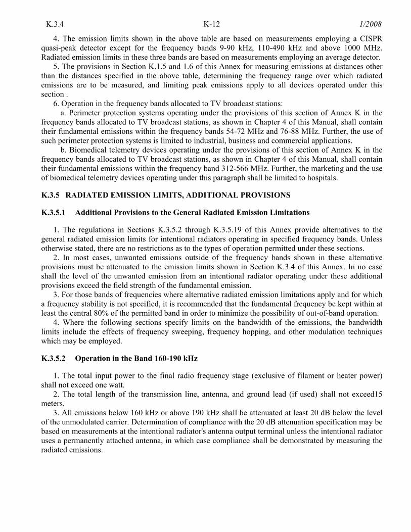
1. Except as provided elsewhere in this part, the emissions from an intentional radiator shall not exceed the field strength levels specified in the following table:
Frequency (MHz) Field Strength (microvolts/meters) Measurement Distance (meters)
0.009-0.490 2400/F (kHz) 300 0.490-1.705 24000/F (kHz) 30 1.705-30.0 30 30
30-88 100* 30 88-216 150* 3
216-960 200* 3 Above 960 500 3
* Except as provided in paragraph 6, fundamental emissions from intentional radiators operating under this part shall not be located in the frequency bands 54-72 MHz, 76-88 MHz, 174-216 MHz, or 470-806 MHz.
2. In the emission table above, the tighter limit applies at the band edges. 3. The level of any unwanted emissions from an intentional radiator operating under these general
provisions shall not exceed the level of the fundamental emission. For intentional radiators which operate under the provisions of other parts and which are required to reduce their unwanted emissions to the limits specified in this table, the limits in this table are based on the frequency of the unwanted emission and not the fundamental frequency. However, the level of any unwanted emissions shall not exceed the level of the fundamental frequency.
K-12 1/2008K.3.4
4. The emission limits shown in the above table are based on measurements employing a CISPR quasi-peak detector except for the frequency bands 9-90 kHz, 110-490 kHz and above 1000 MHz. Radiated emission limits in these three bands are based on measurements employing an average detector.
5. The provisions in Section K.1.5 and 1.6 of this Annex for measuring emissions at distances other than the distances specified in the above table, determining the frequency range over which radiated emissions are to be measured, and limiting peak emissions apply to all devices operated under this section .
6. Operation in the frequency bands allocated to TV broadcast stations: a. Perimeter protection systems operating under the provisions of this section of Annex K in the
frequency bands allocated to TV broadcast stations, as shown in Chapter 4 of this Manual, shall contain their fundamental emissions within the frequency bands 54-72 MHz and 76-88 MHz. Further, the use of such perimeter protection systems is limited to industrial, business and commercial applications.
b. Biomedical telemetry devices operating under the provisions of this section of Annex K in the frequency bands allocated to TV broadcast stations, as shown in Chapter 4 of this Manual, shall contain their fundamental emissions within the frequency band 312-566 MHz. Further, the marketing and the use of biomedical telemetry devices operating under this paragraph shall be limited to hospitals.
K.3.5 RADIATED EMISSION LIMITS, ADDITIONAL PROVISIONS
K.3.5.1 Additional Provisions to the General Radiated Emission Limitations
1. The regulations in Sections K.3.5.2 through K.3.5.19 of this Annex provide alternatives to the general radiated emission limits for intentional radiators operating in specified frequency bands. Unless otherwise stated, there are no restrictions as to the types of operation permitted under these sections.
2. In most cases, unwanted emissions outside of the frequency bands shown in these alternative provisions must be attenuated to the emission limits shown in Section K.3.4 of this Annex. In no case shall the level of the unwanted emission from an intentional radiator operating under these additional provisions exceed the field strength of the fundamental emission.
3. For those bands of frequencies where alternative radiated emission limitations apply and for which a frequency stability is not specified, it is recommended that the fundamental frequency be kept within at least the central 80% of the permitted band in order to minimize the possibility of out-of-band operation.
4. Where the following sections specify limits on the bandwidth of the emissions, the bandwidth limits include the effects of frequency sweeping, frequency hopping, and other modulation techniques which may be employed.
K.3.5.2 Operation in the Band 160-190 kHz
1. The total input power to the final radio frequency stage (exclusive of filament or heater power) shall not exceed one watt.
2. The total length of the transmission line, antenna, and ground lead (if used) shall not exceed15 meters.
3. All emissions below 160 kHz or above 190 kHz shall be attenuated at least 20 dB below the level of the unmodulated carrier. Determination of compliance with the 20 dB attenuation specification may be based on measurements at the intentional radiator's antenna output terminal unless the intentional radiator uses a permanently attached antenna, in which case compliance shall be demonstrated by measuring the radiated emissions.
K-13 1/2008 K.3.5.3
K.3.5.3 Operation in the Band 510-1705 kHz
1. The total input power of the final radio frequency stage (exclusive of filament or heater power) shall not exceed 100 milliwatts.
2. The total length of the transmission line, antenna and ground lead (if used) shall not exceed 3 meters.
3. All emissions below 510 kHz or above 1705 kHz shall be attenuated at least 20 dB below the level of the unmodulated carrier. Determination of compliance with the 20 dB attenuation specification may be based on measurements at the intentional radiator's antenna output terminal unless the intentional radiator uses a permanently attached antenna, in which case compliance shall be demonstrated by measuring the radiated emissions.
K.3.5.4 Operation in the Band 525-1705 kHz
1. The provisions of this section are restricted to the operation of an AM broadcast station on a college or university campus or on the campus of any other educational institution. Operation is restricted to the grounds of the campus. For the band 535-1705 kHz, the frequency of operation shall be chosen such that operation is not within the protected field strength contours of licensed AM stations.
2. On the campus, the field strength of emissions appearing outside of this frequency band shall not exceed the general radiated emission limits shown in Section K.3.4 of this Annex as measured from the radiating source. There is no limit on the field strength of emissions appearing within this frequency band, except that the provisions of Section 7.8 of the NTIA Manual continue to apply.
3. At the perimeter of the campus, the field strength of any emissions, including those within the frequency band 525-1705 kHz shall not exceed the general radiated emission limits in Section K.3.4 of this Annex.
4. The conducted limits specified in Section K.3.3 of this Annex apply to the radio frequency voltage on the public utility power lines outside of the campus. Due to the large number of radio frequency devices which may be used on the campus, contributing to the conducted emissions, as an alternative to measuring conducted emissions on the AC power lines outside of the campus, it is acceptable to demonstrate compliance with this provisions by measuring each individual intentional radiator employed in the system at the point where it connects to the AC power lines. As provided inSection K.3.3, paragraph 2 of this Annex, if only a carrier current system is employed, the AC power line conducted limits do not apply. However, the radiated emission limits provided in this section apply to carrier current systems.
K.3.5.5 Operation in the Band 1.705-10 MHz
1. The field strength of any emission within the band 1.705-10 MHz shall not exceed 100 microvolts/meter at a distance of 30 meters. However, if the bandwidth of the emission is less than 10% of the center frequency, the field strength shall not exceed 15 microvolts/meter or (the bandwidth of the device in kHz) divided by (the center frequency of the device in MHz) microvolts/meter at a distance of 30 meters, whichever is the higher level. For the purposes of this section, bandwidth is determined at the point 6 dB down from the modulated carrier. The emission limits in this paragraph are based on measurement instrumentation employing an average detector. The provisions in Section K.1.5 of this Annex for limiting peak emissions apply.
2. The field strength of emissions outside of the band 1.705-10 MHz shall not exceed the general radiated emission limits in Section K.3.4 of this Annex.
K-14 1/2008K.3.5.6
K.3.5.6 Operation Within the Band 13.553-13.567 MHz
1. The field strength of any emission within this band shall not exceed 10,000 microvolts/meter at 30 meters.
2. The field strength of any emissions appearing outside of this band shall not exceed the general radiated emission limits shown in Section K.3.4 of this Annex.
3. The frequency tolerance of the carrier signal shall be maintained within ±0.01% of the operating frequency over a temperature variation of -20 degrees to +50 degrees C at normal supply voltage, and for a variation in the primary supply voltage from 85% to 115% of the rated supply voltage at a temperature of 20 degrees C. For battery operated equipment, the equipment tests shall be performed using a new battery.
K.3.5.7 Operation Within the Band 26.96-27.28 MHz
1. The field strength of any emission within this band shall not exceed 10,000 microvolts/meter at 3 meters. The emission limit in this paragraph is based on measurement instrumentation employing an average detector. The provisions in Section K.1.5 of this Annex for limiting peak emissions apply.
2. The field strength of any emissions which appear outside of this band shall not exceed the general radiated emission limits in Section K.3.4 of this Annex.
K.3.5.8 Operation Within the Band 40.66-40.70 MHz
1. Unless operating pursuant to the provisions in Section K.3.5.9 of this Annex, the field strength of any emission within this band shall not exceed 1000 microvolts/meter at 3 meters.
2. As an alternative to the limit in paragraph 1, perimeter protection systems may demonstrate compliance with the following: the field strength of any emissions within this band shall not exceed 500 microvolts/meter at 3 meters, as determined using measurement instrumentation employing an average detector. The provisions of Section K.1.5 of this Annex for limiting peak emissions apply where compliance of these devices is demonstrated under this alternative emission limit.
3. The field strength of any emissions appearing outside of this band shall not exceed the general radiated emission limits in Section K.3.4 of this Annex.
4. The frequency tolerance of the carrier signal shall be maintained within ±0.01% of the operating frequency over a temperature variation of -20 degrees to +50 degrees C at normal supply voltage, and for a variation in the primary supply voltage from 85% to 115% of the rated supply voltage at a temperature of 20 degrees C. For battery operated equipment, the equipment tests shall be performed using a new battery.
K.3.5.9 Periodic Operation in the Band 40.66-40.70 MHz and Above 70 MHz
1. The provisions of this section are restricted to periodic operation within the band 40.66-40.70 MHz and above 70 MHz. Except as shown in paragraph 5 of this section, the intentional radiator is restricted to the transmission of a control signal such as those used with alarm systems, door openers, remote switches, etc. Radio control of toys is not permitted. Continuous transmissions, such as voice or video, and data transmissions, are not permitted. The prohibition against data transmissions does not preclude the use of recognition codes. Those codes are used to identify the sensor that is activated or to identify the particular component as being part of the system. The following conditions shall be met to comply with the provisions for this periodic operation:
a. A manually operated transmitter shall employ a switch that will automatically deactivate the transmitter within not more than 5 seconds of being released.

K-15 1/2008 K.3.5.9
b. A transmitter activated automatically shall cease transmission within 5 seconds after activation. c. Periodic transmissions at regular predetermined intervals are not permitted. However, polling or
supervision transmissions to determine system integrity or transmitters used in security or safety applications are allowed if the periodic rate of transmission does not exceed one transmission of not more than one second duration per hour for each transmitter.
d. Intentional radiators which are employed for radio control purposes during emergencies involving fire, security, and safety of life, when activated to signal an alarm, may operate during the pendency of the alarm condition.
2. In addition to the provisions of Section K.3.2 of this Annex, the field strength of emissions from intentional radiators operated under this section shall not exceed the following:
Fundamental Frequency
(MHz) Field Strength of Fundamental
(microvolts/meters) Field Strength of Spurious Emissions
(microvolts/meters) 40.66-40.70 2,-250 225
70-130 1,250 125 130-174 1,250 to 3,750* 125 to 375* 174-260 3,750 375 260-470 2,750 to 12,500* 375 to 1,250*
Above 470 12,500 1,250 * linear interpolations
a. The above field strength limits are specified at a distance of 3 meters. The tighter limits apply at
the band edges. b. Intentional radiators operating under the provisions of this section shall demonstrate compliance
with the limits on the field strength of emissions, as shown in the above table, based on the average value of the measured emissions. As an alternative, compliance with the limits in the above table may be based on the use of measurement instrumentation with a CISPR quasi-peak detector. The specific method of measurement employed shall be specified in the application for equipment authorization. If average emission measurements are employed, the provisions in Section K.1.5 of this Annex for averaging pulsed emissions and for limiting peak emissions apply. Further, compliance with the provisions of Section K.3.2 of this Annex shall be demonstrated using measurement instrumentation with a CISPR quasi-peak detector.
c. The limits on the field strength of the spurious emissions in the above table are based on the fundamental frequency of the intentional radiator. Spurious emissions shall be attenuated to the average limits shown in this table or to the general limits shown in Section K.3.4 of this Annex, as measured with a CISPR quasi-peak detector, whichever limit permits a higher field strength.
3. The bandwidth of the emission shall be no wider than 0.25% of the center frequency for devices operating above 70 MHz and below 900 MHz. For devices operating above 900 MHz, the emission shall be no wider than 0.5% of the center frequency. Bandwidth is determined at the points 20 dB down from the modulated carrier.
4. For devices operating within the frequency band 40.66-40.70 MHz, the bandwidth of the emission shall be confined within the band edges and the frequency tolerance of the carrier shall be ±0.01%. This frequency tolerance shall be maintained for a temperature variation of -20 degrees to +50 degrees C at normal supply voltage, and for a variation in the primary supply voltage from 85% to 115% of the rated supply voltage at a temperature of 20 degrees C. For battery operated equipment, the equipment tests shall be performed using a new battery.
5. Intentional radiators may operate at a periodic rate exceeding that specified in paragraph 1 and may be employed for any type of operation, including operation prohibited in paragraph 1, provided the intentional radiator complies with the provisions of paragraphs 2 through 4 of this section, except the field strength table in paragraph 2 is replaced by the following:
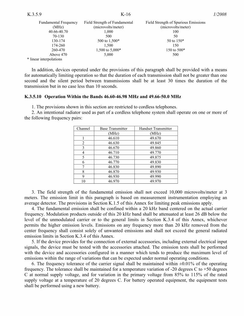
K-16 1/2008K.3.5.9
Fundamental Frequency (MHz)
Field Strength of Fundamental (microvolts/meter)
Field Strength of Spurious Emissions (microvolts/meter)
40.66-40.70 1,000 100 70-130 500 50
130-174 500 to 1,500* 50 to 150* 174-260 1,500 150 260-470 1,500 to 5,000* 150 to 500*
Above 470 5,000 500 * linear interpolations
In addition, devices operated under the provisions of this paragraph shall be provided with a means
for automatically limiting operation so that the duration of each transmission shall not be greater than one second and the silent period between transmissions shall be at least 30 times the duration of the transmission but in no case less than 10 seconds.
K.3.5.10 Operation Within the Bands 46.60-46.98 MHz and 49.66-50.0 MHz
1. The provisions shown in this section are restricted to cordless telephones. 2. An intentional radiator used as part of a cordless telephone system shall operate on one or more of
the following frequency pairs:
Channel Base Transmitter Handset Transmitter (MHz) (MHz)
1 46.610 49.670 2 46.630 49.845 3 46.670 49.860 4 46.710 49.770 5 46.730 49.875 6 46.770 49.830 7 46.830 49.890 8 46.870 49.930 9 46.930 49.990
10 46.970 49.970 3. The field strength of the fundamental emission shall not exceed 10,000 microvolts/meter at 3
meters. The emission limit in this paragraph is based on measurement instrumentation employing an average detector. The provisions in Section K.1.5 of this Annex for limiting peak emissions apply.
4. The fundamental emission shall be confined within a 20 kHz band centered on the actual carrier frequency. Modulation products outside of this 20 kHz band shall be attenuated at least 26 dB below the level of the unmodulated carrier or to the general limits in Section K.3.4 of this Annex, whichever permits the higher emission levels. Emissions on any frequency more than 20 kHz removed from the center frequency shall consist solely of unwanted emissions and shall not exceed the general radiated emission limits in Section K.3.4 of this Annex.
5. If the device provides for the connection of external accessories, including external electrical input signals, the device must be tested with the accessories attached. The emission tests shall be performed with the device and accessories configured in a manner which tends to produce the maximum level of emissions within the range of variations that can be expected under normal operating conditions.
6. The frequency tolerance of the carrier signal shall be maintained within ±0.01% of the operating frequency. The tolerance shall be maintained for a temperature variation of -20 degrees C to +50 degrees C at normal supply voltage, and for variation in the primary voltage from 85% to 115% of the rated supply voltage at a temperature of 20 degrees C. For battery operated equipment, the equipment tests shall be performed using a new battery.
K-17 1/2008 K.3.5.11
K.3.5.11 Operation Within the Band 49.82-49.90 MHz
1. The field strength of any emission within this band shall not exceed 10,000 microvolts/meter at 3 meters. The emission limit in this paragraph is based on measurement instrumentation employing an average detector. The provisions in Section K.1.5 of this Annex for limiting peak emissions apply.
2. The field strength of any emissions appearing between the band edges and up to 10 kHz above and below the band edges shall be attenuated at least 26 dB below the level of the unmodulated carrier or to the general limits in Section K.3.4 of this Annex, whichever permits the higher emission levels. The field strength of any emissions removed by more than 10 kHz from the band edges shall not exceed the general radiated emission limits in Section K.3.4 of this Annex. All signals exceeding 20 microvolts/meter at 3 meters shall be reported in the application for certification.
K.3.5.12 Operation in the Bands 72.0-73.0 MHz and 75.4-76.0 MHz
1. The intentional radiator shall be restricted to use as an auditory assistance device. 2. Emissions from the intentional radiator shall be confined within a band 200 kHz wide centered on
the operating frequency. The 200 kHz band shall lie wholly within the above specified frequency ranges. 3. The field strength of any emissions within the permitted 200 kHz band shall not exceed 80
millivolts/meter at 3 meters. The field strength of any emissions radiated on any frequency outside of the specified 200 kHz band shall not exceed 1500 microvolts/meter at 3 meters. The emission limits in this paragraph are based on measurement instrumentation employing an average detector. The provisions in Section K.1.5 of this Annex for limiting peak emissions apply.
K.3.5.13 Operation in the Band 88-108 MHz
1. Emissions from the intentional radiator shall be confined within a band 200 kHz wide centered on the operating frequency. The 200 kHz band shall lie wholly within the frequency range 88-108 MHz.
2. The field strength of any emissions within the permitted 200 kHz band shall not exceed 250 microvolts/meter at 3 meters. The emission limit in this paragraph is based on measurement instrumentation employing an average detector. The provisions in Section K.1.5 of this Annex for limiting peak emissions apply.
3. The field strength of any emissions radiated on any frequency outside of the specified 200 kHz band shall not exceed the general radiated emission limits in Section K.3.4 of this Annex.
K.3.5.14 Operation in the Band 174-216 MHz
1. Operation under the provisions of this section is restricted to biomedical telemetry devices. 2. Emissions from the device shall be confined within a 200 kHz band which shall lie wholly within
the frequency range 174-216 MHz. 3. The field strength of any emissions radiated within the specified 200 kHz band shall not exceed
1500 microvolts/meter at 3 meters. The field strength of emissions radiated on any frequency outside of the specified 200 kHz band shall not exceed 150 microvolts/meter at 3 meters. The emission limits in this paragraph are based on measurement instrumentation employing an average detector. The provisions in Section K.1.5 of this Annex for limiting peak emissions apply.
K.3.5.15 Operation in the Band 890-940 MHz
1. Operation under the provisions of this section is restricted to devices that use radio frequency energy to measure the characteristics of a material. Devices operated pursuant to the provisions of this section shall not be used for voice communications or the transmission of any other type of message.
K-18 1/2008K.3.5.15
2. The field strength of any emissions radiated within the specified frequency band shall not exceed 500 microvolts/meter at 30 meters. The emission limit in this paragraph is based on measurement instrumentation employing an average detector. The provisions in Section K.1.5 of this Annex for limiting peak emissions apply.
3. The field strength of emissions radiated on any frequency outside of the specified band shall not exceed the general radiated emission limits in Section K.3.4 of this Annex.
4. The device shall be self-contained with no external or readily accessible controls which may be adjusted to permit operation in a manner inconsistent with the provisions of this section. Any antenna that may be used with the device shall be permanently attached thereto and shall not be readily modifiable by the user.
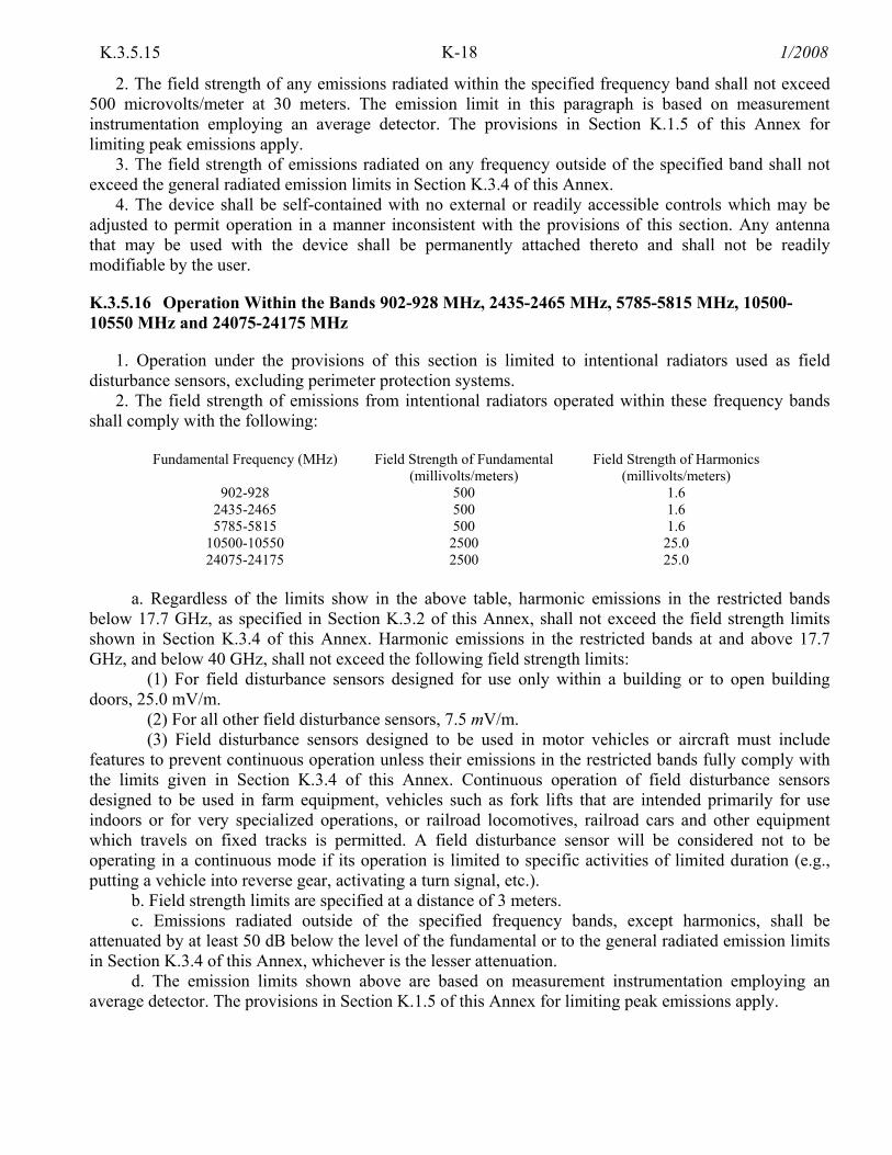
K.3.5.16 Operation Within the Bands 902-928 MHz, 2435-2465 MHz, 5785-5815 MHz, 10500-10550 MHz and 24075-24175 MHz
1. Operation under the provisions of this section is limited to intentional radiators used as field disturbance sensors, excluding perimeter protection systems.
2. The field strength of emissions from intentional radiators operated within these frequency bands shall comply with the following:
Fundamental Frequency (MHz) Field Strength of Fundamental
(millivolts/meters) Field Strength of Harmonics
(millivolts/meters) 902-928 500 1.6
2435-2465 500 1.6 5785-5815 500 1.6
10500-10550 2500 25.0 24075-24175 2500 25.0
a. Regardless of the limits show in the above table, harmonic emissions in the restricted bands
below 17.7 GHz, as specified in Section K.3.2 of this Annex, shall not exceed the field strength limits shown in Section K.3.4 of this Annex. Harmonic emissions in the restricted bands at and above 17.7 GHz, and below 40 GHz, shall not exceed the following field strength limits:
(1) For field disturbance sensors designed for use only within a building or to open building doors, 25.0 mV/m.
(2) For all other field disturbance sensors, 7.5 mV/m. (3) Field disturbance sensors designed to be used in motor vehicles or aircraft must include
features to prevent continuous operation unless their emissions in the restricted bands fully comply with the limits given in Section K.3.4 of this Annex. Continuous operation of field disturbance sensors designed to be used in farm equipment, vehicles such as fork lifts that are intended primarily for use indoors or for very specialized operations, or railroad locomotives, railroad cars and other equipment which travels on fixed tracks is permitted. A field disturbance sensor will be considered not to be operating in a continuous mode if its operation is limited to specific activities of limited duration (e.g., putting a vehicle into reverse gear, activating a turn signal, etc.).
b. Field strength limits are specified at a distance of 3 meters. c. Emissions radiated outside of the specified frequency bands, except harmonics, shall be
attenuated by at least 50 dB below the level of the fundamental or to the general radiated emission limits in Section K.3.4 of this Annex, whichever is the lesser attenuation.
d. The emission limits shown above are based on measurement instrumentation employing an average detector. The provisions in Section K.1.5 of this Annex for limiting peak emissions apply.

K-19 1/2008 K.3.5.17
K.3.5.17 Operation Within the Bands 902-928 MHz, 2400-2483.5 MHz and 5725-5850 MHz
1. Operation under the provisions of this section is limited to frequency hopping and direct sequence spread spectrum intentional radiators that comply with the following provisions:
a. Frequency hopping systems shall have hopping channel carrier frequencies separated by a minimum of 25 kHz or the 20 dB bandwidth of the hopping channel, whichever is greater. The system shall hop to channel frequencies that are selected at the system hopping rate from a pseudo randomly ordered list of hopping frequencies. Each frequency must be used equally on the average by each transmitter. The system receivers shall have input bandwidths that match the hopping channel bandwidths of their corresponding transmitters and shall shift frequencies in synchronization with the transmitted signals.
(1) For frequency hopping systems operating in the 902-928 MHz band: if the 20 dB bandwidth of the hopping channel is less than 250 kHz, the system shall use at least 50 hopping frequencies and the average time of occupancy on any frequency shall not be greater than 0.4 seconds within a 20 second period; if the 20 dB bandwidth of the hopping channel is 250 kHz or greater, the system shall use at least 25 hopping frequencies and the average time of occupancy on any frequency shall not be greater than 0.4 seconds within a 10 second period. The maximum allowed 20 dB bandwidth of the hopping channel is 500 kHz.
(2) Frequency hopping systems operating in the 2400-2483.5 MHz and 5725-5850 MHz bands shall use at least 75 hopping frequencies. The maximum 20 dB bandwidth of the hopping channel is 1 MHz. The average time of occupancy on any frequency shall not be greater than 0.4 seconds within a 30 second period.
b. For direct sequence systems, the minimum 6 dB bandwidth shall be at least 500 kHz. 2. The maximum peak output power of the intentional radiator shall not exceed the following: a. For frequency hopping systems operating in the 2400-2483.5 MHz or 5725-5850 MHz band and
for all direct sequence systems: 1 watt. b. For frequency hopping systems operating in the 902-928 MHz: 1 watt for systems employing at
least 50 hopping channels; and, 0.25 watts for systems employing less than 50 hopping channels, but at least 25 hopping channels, as permitted under subparagraph 1.a.(1) of this section.
c. Except as shown below, with a transmitting antenna having directional gain greater than 6 dBi, the peak output power from the intentional radiator shall be reduced below the above stated values by the amount in dB that the directional gain of the antenna exceeds 6 dBi.
(1) Systems operating in the 2400-2483.5 MHz band that are used exclusively for fixed, point-to-point operations may employ transmitting antennas with directional gain greater than 6 dBi provided the maximum peak output power of the intentional radiator is reduced by 1 dB for every 3 dB that the directional gain of the antenna exceeds 6 dBi.
(2) Systems operating in the 5725-5850 MHz band that are used exclusively for fixed, point-to-point operations my employ transmitting antennas with directional gain greater than 6 dBi without any corresponding reduction in transmitter peak output power.
(3) Fixed, point-to-point operation, as used in subparagraphs 2.c.(1) and 2.c.(2) of this subsection, excludes the use of point-to-multipoint systems, omnidirectional applications, and multiple co-located intentional radiators transmitting the same information. The operator of the spread spectrum intentional radiator or, if the equipment is professionally installed, the installer is responsible for ensuring that the system is used exclusively for fixed, point-to-point operations. The instruction manual furnished with the radiator shall contain language in the instillation instructions informing the operator and the installer of this responsibility.

K-20 1/2008K.3.5.17
(4) Systems operating under the provisions of this part shall be operated in a manner that ensures that the public is not exposed to radio frequency energy levels in excess of the national guidelines expressed in this manual in Section 8.2.28.
3. In any 100 kHz bandwidth outside the frequency band, in which the spread spectrum intentional radiator is operating, the radio frequency power that is produced by the intentional radiator shall be at least 20 dB below that in the 100 kHz bandwidth within the band that contains the highest level of the desired power, based on either an RF conducted or a radiated measurement, whichever yields the highest value. Attenuation below the general limits specified in paragraph 1 of Section K.3.4 is not required. In addition, radiated emissions which fall in the restricted bands, as defined in Section K.3.2, must also comply with the radiated emission limits specified in paragraph 1 of Section K.3.4.
4. For direct sequence systems, the peak power spectral density conducted from the intentional radiator to the antenna shall not be greater than 8 dBm in any 3 kHz band during any time interval of continuous transmission.
5. The processing gain of a direct sequence system shall be at least 10 dB. The processing gain represents the improvement to the received signal-to-noise ratio, after filtering to the information bandwidth, from the spreading/despreading function. The processing gain may be determined using one of the following methods:
a. As measured at the demodulated output of the receiver: the ratio in dB of the signal-to-noise ratio with the system spreading code turned off to the signal-to-noise ratio with the systems spreading code turned on.
b. As measured using the CW jamming margin method: a signal generator is stepped in 50 kHz increments across the passband of the system, recording at each point the generator level required to produce the recommended Bit Error Rate (BER). This level is the jammer level the output power of the intentional radiator is measured at the same point. Then jammer-to-signal ratio (J/S) is then calculated, discarding the worst 20% of the J/S data points. The lowest remaining J/S ratio is used to calculate the processing gain, as follows: Gp=(S/N)O+Mj+Lsys, where Gp=processing gain of the system, (S/N)O=signal-to-noise ratio required for the chosen BER, Mj=J/S ratio, and Lsys=system losses.
Note that total losses in a system, including intentional radiator and receiver, should be assumed to be no more than 2 dB.
6. Hybrid systems that employ a combination of both direct sequence and frequency hopping modulation techniques shall achieve a processing gain of at least 17 dB from the combined techniques. The frequency hopping operation of the hybrid system, with the direct sequence operation turned off, shall have an average time of occupancy on any frequency not to exceed 0.4 seconds within a time period in seconds equal to the number of hopping frequencies employed multiplied by 0.4. The direct sequence operation of the hybrid system, with the frequency hopping operation turned off, shall comply with the power density requirements of paragraph 4 of this Section.
7. Frequency hopping spread spectrum systems are not required to employ all available hopping channels during each transmission. However, the system, consisting of both the transmitter and the receiver, must be designed to comply with all of the regulations in this section should the transmitter be presented with a continuous data (or information) stream. In addition, a system employing short transmission bursts must comply with the definition of a frequency hopping system and must distribute its transmissions over the minimum number of hopping channels specified in this section.
8. The incorporation of intelligence within a frequency hopping spread spectrum system that permits the system to recognize other users within the spectrum band so that it individually and independently chooses and adapts its hopsets to avoid hopping on occupied channels is permitted. The coordination of frequency hopping systems in any other manner for the express purpose of avoiding the simultaneous occupancy of individual hopping frequencies by multiple transmitters is not permitted.

K-21 1/2008 K.3.5.17
NOTE: Spread spectrum systems are sharing these bands on a non-interference basis with systems supporting critical Federal requirements that have been allocated the usage of these bands, secondary only to ISM equipment. Many of these Federal systems are airborne radiolocation systems that emit a high EIRP which can cause interference to other users. Also, investigations of the effect of spread spectrum interference to U.S. Government operations in the 902-938 MHz band may require a future decrease in the power limits allowed for spread spectrum operation.
K.3.5.18 Operation Within the Bands 902-928 MHz 2400-2483.5 MHz, 5725-5875 MHz and 24.0-24.25 GHz
1. The field strength from intentional radiators operated within these frequency bands shall comply with the following:
Fundamental Frequency
Field Strength of Fundamental (millivolts/meter)
Field Strength of Harmonics (microvolts/meter)
902-928 MHz 50 500 2400-2483.5 MHz 50 500 5725-5875 MHz 50 500 24.0-24.25 GHz 250 2500
2. Field strength limits are specified at a distance of 3 meters. 3. Emissions radiated outside of the specified frequency bands, except for harmonics, shall be
attenuated by at least 50 dB below the level of the fundamental or to the general radiated emission limits in Section K.3.4 of this Annex, whichever is the lesser attenuation.
4. As shown in Section K.1.5 of this Annex, for frequencies above 1000 MHz, the above field strength limits are based on average limits. However, the peak field strength of any emission shall not exceed the maximum permitted average limits specified above by more than 20 dB under any condition of modulation.
K.3.5.19 Operation Within the Bands 2.9-3.26 GHz, 3.267-3.332 GHz, 3.339-3.3458 GHz and 3.358-3.6 GHz
1. Operation under the provisions of this section is limited to automatic vehicle identification systems (AVIS) which use swept frequency techniques for the purpose of automatically identifying transportation vehicles.
2. The field strength anywhere within the frequency range swept by the signal shall not exceed 3000 microvolts/meter/MHz at 3 meters in any direction. Further, an AVIS, when in its operating position, shall not produce a field strength greater than 400 microvolts/meter/MHz at 3 meters in any direction within ±10 degrees of the horizontal plane. In addition to the provisions of Section K.3.2 of this Annex, the field strength of radiated emissions outside the frequency range swept by the signal shall be limited to a maximum of 100 microvolts/meter/MHz at 3 meters, measured from 30 MHz to 20 GHz for the complete system. The emission limits in this paragraph are based on measurement instrumentation employing an average detector. The provisions in Section K.1.5 of this Annex for limiting peak emissions apply.
3. The minimum sweep repetition rate of the signal shall not be lower than 4000 sweeps per second, and the maximum sweep repetition rate of the signal shall not exceed 50,000 sweeps per second.
4. An AVIS shall employ a horn antenna or other comparable directional antenna for signal emission. 5. Provision shall be made so that signal emission from the VIS shall occur only when the vehicle to
be identified is within the radiated field of the system.

K-22 1/2008K.3.5.20
K.3.5.20 Unlicensed National Information Infrastructure Devices
K.5.20.1 General These paragraphs set out the regulations for Unlicensed National Information Infrastructure devices
operating in the 5.15-5.35 GHz and 5.725-5.825 GHz bands. The provisions of all other parts of this Annex apply to unlicensed devices except where specific provisions are contained in this part. The requirements of this part apply only to the radio transmitter contained in the Section K.3.5.20. Other aspects of the operation of such devices may be subject to requirements contained elsewhere in this annex. In particular, such devices that include digital circuitry not directly associated with the radio transmitter in this section are also subject to the requirement for unintentional radiators found elsewhere in this annex.
K.3.5.20.2 U-NII Definitions Average Symbol Envelope Power: The average symbol envelope power is the average, taken over
all symbols in the signaling alphabet, of the envelope power for each symbol. Digital Modulation: The process by which the characteristics of a carrier wave are varied among a
set of predetermined discrete values in accordance with a digital modulating function as specified in document ANSI C63.17-1998.
Emission Bandwidth: For the purposes of this subpart the emission bandwidth shall be determined by measuring the width of the signal between two points, one below the carrier center frequency and one above the carrier center frequency, that are 26 dB down relative to the maximum level of the modulated carrier. Determination of the emission bandwidth is based on the use of measurement instrumentation employing a peak detector function with an instrument resolution bandwidth approximately equal to 1.0 percent of the emission bandwidth of the device under measurement.
Peak Power Spectral Density: The peak power spectral density is the maximum power spectral density, within the specified measurement bandwidth, within the device's operating band.
Peak Transmit Power: The maximum transmit power as measured over an interval of time of at most 30/B (where B is the 26-dB emission bandwidth in MHz) or the transmission pulse duration of the device, whichever is less, under all conditions of modulation.
Power Spectral Density: The power spectral density is the total energy output per unit bandwidth from a pulse or sequence of pulses for which the transmit power is at its peak or maximum level, divided by the total duration of the pulses. This total time does not include the time between pulses during which the transmit power is off or below its maximum level.
Pulse: A pulse is a continuous transmission of a sequence of modulation symbols, during which the average symbol envelope power is constant.
Transmit Power: The total energy transmitted over a time interval of at most 30/B (where B is the 26 dB emission bandwidth of the signal in hertz) or the duration of the transmission pulse, whichever is less, divided by the interval duration.
U-NII devices: Intentional radiators operating in the frequency bands 5.15 - 5.35 GHz and 5.725 -5.825 GHz that use wideband digital modulation techniques and provide a wide array of high data rate mobile and fixed communications for individuals, businesses, and institutions.
K.3.5.20.3 U-NII General Technical Requirements a. Power limits:

K-23 1/2008 K.3.5.20.3
(1) For the band 5.15-5.25 GHz, the peak transmit power over the frequency band of operation shall not exceed the lesser of 50 mW or 4 dBm + 10logB (where B is the 26-dB emission bandwidth in MHz). In addition, the peak power spectral density shall not exceed 4 dBm in any 1-MHz band. If transmitting antennas of directional gain greater than 6 dBi are used, both the peak transmit power and the peak power spectral density shall be reduced by the amount in dB that the directional gain of the antenna exceeds 6 dBi.
(2) For the band 5.25-5.35 GHz, the peak transmit power over the frequency band of operation shall not exceed the lesser of 250 mW or 11 dBm + 10logB (where B is the 26-dB emission bandwidth in MHz). In addition, the peak power spectral density shall not exceed 11 dBm in any 1-MHz band. If transmitting antennas of directional gain greater than 6 dBi are used, both the peak transmit power and the peak power spectral density shall be reduced by the amount in dB that the directional gain of the antenna exceeds 6 dBi.
(3) For the band 5.725-5.825 GHz, the peak transmit power over the frequency band of operation shall not exceed 1 W or 17 dBm + 10logB (where B is the 26-dB emission bandwidth in MHz). In addition, the peak power spectral density shall not exceed 17 dBm in any 1-MHz band. If transmitting antennas of directional gain greater than 6 dBi are used, both the peak transmit power and the peak power spectral density shall be reduced by the amount in dB that the directional gain of the antenna exceeds 6 dBi. However, fixed point-to-point U-NII devices operating in this band may employ transmitting antennas with directional gain up to 23 dBi without any corresponding reduction in the transmitter peak output power or peak power spectral density. For fixed, point-to-point U-NII transmitters that employ a directional antenna gain greater than 23 dBi, a 1 dB reduction in peak transmitter power and peak power spectral density for each 1 dB of antenna gain in excess of 23 dBi would be required. Fixed, point-to-point operations exclude the use of point-to-multipoint systems, omnidirectional applications, and multiple collocated transmitters transmitting the same information. The operator of the device, or if the equipment is professionally installed, the installer, is responsible for ensuring that systems employing high gain directional antennas are used exclusively for fixed, point-to-point operations.
NOTE: The NTIA strongly recommends that parties employing these devices to provide critical communications services should determine if there are any nearby Federal radar systems that could affect their operation.
(4) The peak transmit power must be measured over any interval of continuous transmission using instrumentation calibrated in terms of an rms-equivalent voltage. The measurement results shall be properly adjusted for any instrument limitations, such as detector response times, limited resolution bandwidth capability when compared to the emission bandwidth, sensitivity, etc., so as to obtain a true peak measurement conforming to the above definitions for the emission in question.
(5) The peak power spectral density is measured as a conducted emission by direct connection of a calibrated test instrument to the equipment under test. If the device cannot be connected directly, alternative techniques acceptable to the Commission may be used. Measurements are made over a bandwidth of 1 MHz or the 26 dB emission bandwidth of the device, whichever is less. A resolution bandwidth less than the measurement bandwidth can be used, provided that the measured power is integrated to show total power over the measurement bandwidth. If the resolution bandwidth is approximately equal to the measurement bandwidth, and much less than the emission bandwidth of the equipment under test, the measured results shall be corrected to account for any difference between the resolution bandwidth of the test instrument and its actual noise bandwidth.
(6) The ratio of the peak excursion of the modulation envelope (measured using a peak hold function) to the peak transmit power (measured as specified above) shall not exceed 13 dB across any 1 MHz bandwidth or the emission bandwidth whichever is less.
K-24 1/2008K.3.5.20.3
b. Undesirable Emission Limits: Except as shown in Paragraph b.(6) of this Section, the peak emissions outside of the frequency bands of operation shall be attenuated in accordance with the following limits:
(1) For transmitters operating in the 5.15-5.25 GHz band: all emissions outside of the 5.15-5.35 GHz band shall not exceed an EIRP of -27 dBm/MHz.
(2) For transmitters operating in the 5.25-5.35 GHz band: all emissions outside of the 5.15-5.35 GHz band shall not exceed an EIRP of -27 dBm/MHz. Devices operating in the 5.25-5.35 GHz band that generate emissions in the 5.15-5.25 GHz band must meet all applicable technical requirements for operation in the 5.15-5.25 GHz band (including indoor use) or alternatively meet an out-of-band emission EIRP limit of -27 dBm/MHz in the 5.15-5.25 GHz band.
(3) For transmitters operating in the 5.725-5.825 GHz band: all emissions within the frequency range from the band edge to 10 MHz above or below the band edge shall not exceed an EIRP of -17 dBm/MHz; for frequencies 10 MHz or greater above or below the band edge, emissions shall not exceed an EIRP of -27 dBm/MHz.
(4) The above emission measurements shall be performed using a minimum resolution bandwidth of 1 MHz. A lower resolution bandwidth may be employed near the band edge, when necessary, provided the measured energy is integrated to show the total power over 1 MHz.
(5) Unwanted emissions below 1 GHz must comply with the general field strength limits set forth in Section K.3.4. Further, any devices using an AC power line are required to comply also with the conducted limits set forth in Section K.3.3.
(6) The provisions of Section K.3.2 of this Annex apply to intentional radiators operating under this section.
(7) When measuring the emission limits, the nominal carrier frequency shall be adjusted as close to the upper and lower frequency block edges as the design of the equipment permits.
c. The device shall automatically discontinue transmission in case of either absence of information to transmit or operational failure. These provisions are not intended to preclude the transmission of control or signaling information or the use of repetitive codes used by certain digital technologies to complete frame or burst intervals. Applicants shall include in their application for equipment authorization a description of how this requirement is met.
d. Any device that operates in the 5.15-5.25 GHz band shall use a transmitting antenna that is an integral part of the device.
e. Within the 5.15-5.25 GHz band, devices will be restricted to indoor operations to reduce any potential for harmful interference to aeronautical radionavigation and co-channel MSS operations.
f. Devices are subject to the radio frequency radiation exposure requirements specified in Section 8.2.28, as appropriate. All equipment shall be considered to operate in a "general population/uncontrolled" environment. Applications for equipment authorization of devices operating under this section must contain a statement confirming compliance with these requirements for both fundamental emissions and unwanted emissions. Technical information showing the basis for this statement must be submitted to the NTIA upon request.
g. Manufacturers of these devices are responsible for ensuring frequency stability such that an emission is maintained within the band of operation under all conditions of normal operation as specified in the users manual.
K-25 1/2008 K.3.5.21
K.3.5.21 Unlicensed Personal Communications Service Devices
K.3.5.21.1 PCS General This section sets out the regulations for unlicensed personal communication service (PCS) operating
in the 1920-1930 MHz band. K.3.5.21.2 PCS Definitions Asynchronous devices: Devices that transmit RF energy at irregular time intervals, as typified by
local area network data systems. Coordinatable PCS device: PCS devices whose geographical area of operation is sufficiently
controlled either by necessity of operation with a fixed infrastructure or by disabling mechanisms to allow adequate coordination of their locations relative to incumbent fixed microwave facilities.
Emission bandwidth: For purposes of this section the emission bandwidth shall be determined by measuring the width of the signal between two points, one below the carrier center frequency and one above the carrier center frequency, that are 26 dB down relative to the maximum level of the modulated carrier. Compliance with the emissions limits is based on the use of measurement instrumentation employing a peak detector function with an instrument resolutions bandwidth approximately equal to 1.0 percent of the emission bandwidth of the device under measurement.
Isochronous devices: Devices that transmit at a regular interval, typified by time-division voice systems.
Non-coordinatable PCS device: A PCS device that is capable of randomly roaming and operating in geographic areas containing incumbent microwave facilities such that operation of the PCS device will potentially cause harmful interference to the incumbent microwave facilities.
Peak transmit power: The peak power output as measured over an interval of time equal to the frame rate or transmission burst of the device under all conditions of modulation. Usually this parameter is measured as a conducted emission by direct connection of a calibrated test instrument to the equipment under test. If the device cannot be connected directly, alternative techniques acceptable to the Commission may be used.
Personal Communications Service (PCS) Devices [Unlicensed]: Intentional radiators operating in the frequency bands 1910-1930 MHz and 2390-2400 MHz that provide a wide array of mobile and ancillary fixed communication services to individuals and businesses.
Spectrum window: An amount of spectrum equal to the intended emission bandwidth in which operation is desired.
Sub-band: For purposes of this section the term sub-band refers to the spectrum allocated for isochronous or asynchronous transmission.
Thermal noise power: The noise power in watts defined by the formula N=kTB where N is the noise power in watts, k is Boltzmann's constant, T is the absolute temperature in degrees Kelvin (e.g., 295° K) and B is the emission bandwidth of the device in hertz.
Time window: An interval of time in which transmission is desired. K.3.5.21.3 PCS Equipment Authorization Requirement PCS devices operating under this Annex shall be authorized by the Commission under the procedures
in Title 47, Subpart J of Part 2 of the FCC Rules and Regulations before marketing. The application for authorization must contain sufficient information to demonstrate compliance with the requirements of this section.
K-26 1/2008K.3.5.21.4
K.3.5.21.4 PCS Coordination with Fixed Microwave Service a. Operations of unlicensed PCS devices are required to protect systems in the Private Operational-
Fixed Microwave Service. Coordination in the Fixed Microwave services is facilitated through UTAM, Inc. (Unlicensed Transition and Management for Microwave relocation in the 2 GHz band). Funding for coordination and relocation of fixed microwave systems, when necessary, is covered by fees payed to UTAM by the manufacturers of the unlicensed PCS devices.
b. Operations under the provisions of this section are required to protect systems in the Private Operational-Fixed Microwave Service operating within the 1850-1990 MHz band until the dates and conditions specified in the FCC Rules and Regulations (under Title 47, Part 101.69 - 101.73) of this section for termination of primary status. Interference protection is not required for Title 47, Part 101 stations in this band licensed on a secondary basis.
c. The operator of a PCS device that is relocated from the coordinated area specified by UTAM, Inc., must cease operating the device until coordination for the new location is verified by UTAM, Inc. UTAM may be contacted at 800-429-8826 or by contacting UTAM, Inc. directly at UTAM, Inc., 991 US Highway 22, Suite 104, P.O. Box 8126, Bridgewater, NJ 08807 (Phone: 908-526-3636 or their FAX: 908-526-0115).
K.3.5.21.5 PCS Labeling Requirements In addition to the labeling requirements of Section K.1.4, all devices operating in the frequency band
1910-1930 MHz authorized under this section must bear a prominently located label with the following statement:
Installation of this equipment is subject to notification and coordination with UTAM, Inc. Any relocation of this equipment must be coordinated through, and approved by UTAM. Directions for contacting UTAM are specified in subparagraph 4.c of this may be contacted at 800-429-8826 or by contacting UTAM, Inc. directly at: UTAM, Inc., 991 US Highway 22, Suite 104, P.O. Box 8126, Bridgewater, NJ 08807 (Phone: 908-526-3636 or their FAX: 908-526-0115).
K.3.5.21.6 PCS Measurement Procedures Measurements must be made in accordance with Annex K, Section K.1.5, except where specific
procedures are specified in Section K.3.5.21. If no guidance is provided, the measurement procedure must be in accordance with good engineering practice.
K.3.5.21.7 PCS Conducted Limits An unlicensed PCS device that is designed to be connected to the public utility (AC) power line must
meet the limits specified in Section K.3.3 of this Annex. K.3.5.21.8 PCS Antenna Requirement An unlicensed PCS device must meet the antenna requirement of Section K.3.1 of this Annex. K.3.5.21.9 PCS General Technical Requirements a. [Reserved] b. All transmissions must use only digital modulation techniques.
K-27 1/2008 K.3.5.21.9
c. Peak transmit power shall not exceed 100 microwatts multiplied by the square root of the emission bandwidth in hertz. Peak transmit power must be measured over any interval of continuous transmission using instrumentation calibrated in terms of an rms-equivalent voltage. The measurement results shall be properly adjusted for any instrument limitations, such as detector response times, limited resolution bandwidth capability when compared to the emission bandwidth, sensitivity, etc., so as to obtain a true peak measurement for the emission in question over the full bandwidth of the channel.
d. Power spectral density shall not exceed 3 milliwatts in any 3 kHz bandwidth as measured with a spectrum analyzer having a resolution bandwidth of 3 kHz.
e. The peak transmit power shall be reduced by the amount in decibels that the maximum directional gain of the antenna exceeds 3 dBi.
f. The device shall automatically discontinue transmission in case of either absence of information to transmit or operational failure. These provisions are not intended to preclude transmission of control and signaling information or use of repetitive codes used by certain digital technologies to complete frame or burst intervals.
g. Notwithstanding other technical requirements specified in this section, attenuation of emissions below the general emission limits in Section K.3.4 is not required.
h. Where there is a transition between limits, the tighter limit shall apply at the transition point. i. Unlicensed PCS devices operating under the provision of this part shall be operated in a manner
that ensures that the public is not exposed to radio frequency energy levels in excess of the national guidelines expressed in this manual in Section 8.2.28.
K.3.5.21.10 Specific Requirements for Devices Operating in the 1920-1930 MHz sub-Band a. Operation shall be contained within one of eight 1.25 MHz channels starting with 1920-1921.25
MHz and ending with 1928.75-1930 MHz. Further sub-division of a 1.25 MHz channel is permitted with a reduced power level, as specified in Section K.3.5.21 subparagraph 9.c., but in no event shall the emission bandwidth be less than 50 kHz.
b. Intentional radiators with an intended emission bandwidth less than 625 kHz shall start searching for an available time and spectrum window within 3 MHz of the sub-band edge at 1920 MHz and search upward from that point. Devices with an intended emission bandwidth greater than 625 kHz shall start searching for an available time and spectrum window within 3 MHz of the sub-band edge at 1930 MHz and search downward from that point.
c. Isochronous devices must incorporate a mechanism for monitoring the time and spectrum windows that its transmission is intended to occupy. The following criteria must be met:
(1) Immediately prior to initiating transmission, devices must monitor the combined time and spectrum windows in which they intend to transmit for a period of at least 10 milliseconds for systems designed to use a 10 millisecond or shorter frame period or at least 20 milliseconds for systems designed to use a 20 millisecond frame period.
(2) The monitoring threshold must not be more than 30 dB above the thermal noise power for a bandwidth equivalent to the emission bandwidth of the device.
(3) If no signal above the threshold level is detected, transmission may commence and continue with the same emission bandwidth in the monitored time and spectrum windows without further monitoring. However, occupation of the same combined time and spectrum windows by a device or group of cooperating devices continuously over a period of time longer than 8 hours is not permitted without repeating the access criteria.
K-28 1/2008K.3.5.21.10
(4) Once access to specific combined time and spectrum windows is obtained an acknowledgement from a system participant must be received by the initiating transmitter within one second or transmission must cease. Periodic acknowledgements must be received at least every 30 seconds or transmission must cease. Channels used exclusively for control and signalling information may transmit continuously for 30 seconds without receiving an acknowledgement, at which time the access criteria must be repeated.
(5) If access to spectrum is not available as determined by the above, and a minimum of 40 duplex system access channels are defined for the system, the time and spectrum windows with the lowest power level below a monitoring threshold of 50 dB above the thermal noise power determined for the emission bandwidth may be accessed. A device utilizing the provisions of this paragraph must have monitored all access channels defined for its system within the last 10 seconds and must verify, within the 20 milliseconds (40 milliseconds for devices designed to use a 20 millisecond frame period) immediately preceding actual channel access that the detected power of the selected time and spectrum windows is no higher than the previously detected value. The power measurement resolution for this comparison must be accurate to within 6 dB. No device or group of cooperating devices located within 1 meter of each other shall occupy more than three 1.25 MHz channels during any frame period. Devices in an operational state that are utilizing the provision of this section are not required to use the search provisions of (b) above.
(6) If the selected combined time and spectrum windows are unavailable, the device may either monitor and select different windows or seek to use the same windows after waiting an amount of time, randomly chosen from a uniform random distribution between 10 and 150 milliseconds, commencing when the channel becomes available.
(7) The monitoring system bandwidth must be equal to or greater than the emission bandwidth of the intended transmission and have a maximum reaction time less than 50xSQRT(1.25/emission bandwidth in MHz) microseconds for signals at the applicable threshold level but shall not be required to be less than 50 microseconds. If a signal is detected that is 6 dB or more above the applicable threshold level, the maximum reaction time shall be 35xSQRT(1.25/emission bandwidth in MHz) microseconds but shall not be required to be less than 35 microseconds.
(8) The monitoring system shall use the same antenna used for transmission, or an antenna that yields equivalent reception at that location.
(9) Devices that have a power output lower than the maximum permitted under the rules may increase their monitoring detection threshold by one decibel for each one decibel that the transmitter power is below the maximum permitted.
(10) An initiating device may attempt to establish a duplex connection by monitoring both its intended transmit and receive time and spectrum windows. If both the intended transmit and receive time and spectrum windows meet the access criteria, then the initiating device can initiate a transmission in the intended transmit time and spectrum window. If the power detected by the responding device can be decoded as a duplex connection signal from the initiating device, then the responding device may immediately begin transmitting on the receive time and spectrum window monitored by the initiating device.
(11) An initiating device that is prevented from monitoring during its intended transmit window due to monitoring system blocking from the transmissions of a co-located (within one meter) transmitter of the same system, may monitor the portions of the time and spectrum windows in which they intend to receive over a period of at least 10 milliseconds. The monitored time and spectrum window must total at least 50 percent of the 10 millisecond frame interval and the monitored spectrum must be within the 1.25 MHz frequency channel(s) already occupied by that device or co-located co-operating devices. If the access criteria is met for the intended receive time and spectrum window under the above conditions, then transmission in the intended transmit window by the initiating device may commence.
K-29 1/2008 K.3.5.21.10
(12) The provisions of Section K.3.5.21 subparagraph 11.c(10) or Section K.3.5.21 subparagraph 11.c(11) shall not be used to extend the range of spectrum occupied over space or time for the purpose of denying fair access to spectrum to other devices.
d. Emissions shall be attenuated below a reference power of 112 milliwatts as follows: 30 dB between the channel edges and 1.25 MHz above or below the channel; 50 dB between 1.25 and 2.5 MHz above or below the channel; and 60 dB at 2.5 MHz or greater above or below the channel. Systems that further sub-divide a 1.25 MHz channel into X sub-channels must comply with the following emission mask: In the bands between 1B and 2B measured from the center of the emission bandwidth the total power emitted by the device shall be at least 30 dB below the transmit power permitted for that device; in the bands between 2B and 3B measured from the center of the emission bandwidth the total power emitted by an intentional radiator shall be at least 50 dB below the transmit power permitted for that radiator; in the bands between 3B and the 1.25 MHz channel edge the total power emitted by an intentional radiator in the measurement bandwidth shall be at least 60 dB below the transmit power permitted for that radiator. "B" is defined as the emission bandwidth of the device in MHz. Compliance with the emission limits is based on the use of measurement instrumentation employing a peak detector function with an instrument resolution bandwidth approximately equal to 1.0 percent of the emission bandwidth of the device under measurement.
e. The frame period (a set of consecutive time slots in which the position of each time slot can be identified by reference to a synchronizing source) of an intentional radiator operating in these sub-bands shall be 20 milliseconds/X where X is a positive whole number. Each device that implements time division for the purposes of maintaining a duplex connection on a given frequency carrier shall maintain a frame repetition rate with a frequency stability of at least 50 parts per millions (ppm). Each device which further divides access in time in order to support multiple communication links on a given frequency carrier shall maintain a frame repetition rate with a frequency stability of at least 10 ppm. The jitter (time-related, abrupt, spurious variations in the duration of the frame interval) introduced at the two ends of such a communication link shall not exceed 25 microseconds for any two consecutive transmissions. Transmissions shall be continuous in every time and spectrum window during the frame period defined for the device.
f. The frequency stability of the carrier frequency of the intentional radiator shall be maintained within ± 10 ppm over 1 hour or the interval between channel access monitoring, whichever is shorter. The frequency stability shall be maintained over a temperature variation of -20° to +50° degrees C at normal supply voltage, and over a variation in the primary supply voltage of 85 percent to 115 percent of the rated supply voltage at a temperature of 20° C. For equipment that is capable only of operating from a battery, the frequency stability tests shall be performed using a new battery without any further requirement to vary supply voltage.
K.3.5.22 Operation within the band 57-64 GHz
1. Operation under the provisions of this section is not permitted for the following products: a. Equipment used on aircraft or satellites, b. Field disturbance sensors, including vehicle radar systems, unless the field disturbance sensors
are employed for fixed operation. For the purposes of this section, the reference to fixed operation includes field disturbance sensors installed in fixed equipment, even if the sensor itself moves within the equipment.
2. Within the 57-64 GHz band, emission levels shall not exceed the following: a. For products other than fixed field disturbance sensors, the average power density of any
emission, measured during the transmit interval, shall not exceed 9 , as measured three meters from the radiating structure, and the peak power density of any emission shall not exceed 18 , as measured three meters from the radiating structure.
2/ cmuW2/ cmuW

K-30 1/2008K.3.5.22
b. For fixed field disturbance sensors that occupy 500 MHz or less of bandwidth and that are contained wholly within the frequency band 61.0-61.5 GHz, the average power density of any emission, measured during the transmit interval, shall not exceed 9 , as measured three meters from the radiating structure, and the peak power density of any emission shall not exceed 18 , as measured three meters from the radiating structure. In addition, the average power density of any emission outside of the 61.0-61.5 GHz band, measured during the transmit interval, but still within the 57-64 GHz band, shall not exceed 9 nW/cm, as measured three meters from the radiating structure, and the peak power density of any emission shall not exceed 18 , as measured three meters from the radiating structure.
2/ cmuW2/ cmuW
2/ cmnW
c. For fixed field disturbance sensors other than those operating under the provisions of paragraph (b)(2) of this section, the peak transmitter output power shall not exceed 0.1 mW and the peak power density shall not exceed 9 at a distance of three meters. 2/ cmnW
d. Peak power density shall be measured with an RF detector that has a detection bandwidth that encompasses the 57-64 GHz band and has a video bandwidth of at least 10 MHz, or using an equivalent measurement method.
e. The average emission limits shall be calculated, based on the measured peak levels, over the actual time period during which transmission occurs.
3. Limits on spurious emissions: a. The power density of any emissions outside the 57-64 GHz band shall consist solely of spurious
emissions. b. Radiated emissions below 40 GHz shall not exceed the general limits in Section 15.209. c. Between 40 GHz and 200 GHz, the level of these emissions shall not exceed 90 pW/cm2 at a
distance of three meters. d. The levels of the spurious emissions shall not exceed the level of the fundamental emission. 4. Only spurious emissions and transmissions related to a publicly-accessible coordination channel,
whose purpose is to coordinate operation between diverse transmitters with a view towards reducing the probability of interference throughout the 57-64 GHz band, are permitted in the 57-57.05 GHz band.
NOTE: The 57-57.05 GHz is reserved exclusively for a publicly-accessible coordination channel. The development of standards for this channel shall be performed pursuant to authorizations issued under Part 5 of this chapter.
5. Except as specified below, the total peak transmitter output power shall not exceed 500 mW. a. Transmitters with an emission bandwidth of less than 100 MHz must limit their peak transmitter
output power to the product of 500 mW times their emission bandwidth divided by 100 MHz. For the purposes of this paragraph, emission bandwidth is defined as the instantaneous frequency range occupied by a steady state radiated signal with modulation, outside which the radiated power spectral density never exceeds 6 dB below the maximum radiated power spectral density in the band, as measured with a 100 kHz resolution bandwidth spectrum analyzer. The center frequency must be stationary during the measurement interval, if not stationary during normal operation (e.g. for frequency hopping devices).
b. Peak transmitter output power shall be measured with an RF detector that has a detection bandwidth that encompasses the 57-64 GHz, band and that has a video bandwidth of at least 10 MHz, or using an equivalent measurement method.
c. For purposes of demonstrating compliance with this paragraph, corrections to the transmitter output power may be made due to the antenna and circuit loss.
6. Fundamental emissions must be contained within the frequency bands specified in this section during all conditions of operation. Equipment is presumed to operate over the temperature range -20 to +50 degrees Celsius with an input voltage variation of 85% to 115% of rated input voltage, unless justification is presented to demonstrate otherwise.

K-31 1/2008 K.3.5.22
7. Regardless of the power density levels permitted under this section, devices operating under the provisions of this section are subject to the radio frequency radiation exposure requirements specified in § 1.1307(b), § 2.1091 and § 2.1093 of this chapter, as appropriate. Applications for equipment authorization of devices operating under this section must contain a statement confirming compliance with these requirements for both fundamental emissions and unwanted emissions. Technical information showing the basis for this statement must be submitted to the Commission upon request.
8. Any transmitter that has received the necessary FCC equipment authorization under the rules of this chapter may be mounted in a group installation for simultaneous operation with one or more other transmitter(s) that have received the necessary FCC equipment authorization, without any additional equipment authorization. However, no transmitter operating under the provisions of this section may be equipped with external phase-locking inputs that permit beam-forming arrays to be realized.
9. For all transmissions that emanate from inside a building, within any one second interval of signal transmission, each transmitter with a peak output power equal to or greater than 0.1 mW or a peak power density equal to or greater than 3 nW/cm2, as measured three meters from the radiating structure, must transmit a transmitter identification at least once. Each application for equipment authorization must declare that the equipment that will be used inside a building contains the required transmitter identification feature and must specify a method whereby interested parties can obtain sufficient information, at no cost, to enable them to fully detect and decode this transmitter identification information. Upon the completion of decoding, the transmitter identification data block must provide the following fields:
a. FCC Identifier, which shall be programmed at the factory, b. Manufacturer's serial number, which shall be programmed at the factory, c. Provision for at least 24 bytes of data relevant to the specific device, which shall be field
programmable. The grantee must implement a method that makes it possible for users to specify and update this data. The recommended content of this field is information to assist in contacting the operator.
K.3.6 OPERATION of NON-LICENSED ULTRAWIDEBAND SYSTEMS (UWB) AND DEVICES
K.3.6.1 Definitions:
ULTRAWIDEBAND (UWB) Bandwidth: UWB bandwidth is the frequency band bounded by the points that are 10 dB below the highest radiated emission, as based on the complete transmission system including the antenna. The upper boundary is designated fH and the lower boundary is designated fL. The frequency at which the highest radiated emission occurs is designated fM.
Center frequency: The center frequency, fC, equals (fH + fL)/2. Fractional bandwidth: The fractional bandwidth equals 2(fH - fL)/(fH + fL). UWB transmitter: An intentional radiator that, at any point in time, has a fractional bandwidth equal
to or greater than 0.20 or has a UWB bandwidth equal to or greater than 500 MHz, regardless of the fractional bandwidth.
Imaging system: A general category of UWB consisting of ground penetrating radar systems, medical imaging systems, wall imaging systems through-wall imaging systems and surveillance systems. As used in this subpart, imaging systems do not include systems designed to detect the location of tags or systems used to transfer voice or data information.
Ground penetrating radar (GPR) system: A field disturbance sensor that is designed to operate only when in contact with, or within one meter of, the ground for the purpose of detecting or obtaining the images of buried objects or determining the physical properties within the ground. The energy from the GPR is intentionally directed down into the ground for this purpose.
K-32 1/2008K.3.6.1
Medical imaging system: A field disturbance sensor that is designed to detect the location or movement of objects within the body of a person or animal.
Wall imaging system: A field disturbance sensor that is designed to detect the location of objects contained within a "wall" or to determine the physical properties within the "wall." The "wall" is a concrete structure, the side of a bridge, the wall of a mine or another physical structure that is dense enough and thick enough to absorb the majority of the signal transmitted by the imaging system. This category of equipment does not include products such as "stud locators" that are designed to locate objects behind gypsum, plaster or similar walls that are not capable of absorbing the transmitted signal.
Through-wall imaging system: A field disturbance sensor that is designed to detect the location or movement of persons or objects that are located on the other side of an opaque structure such as a wall or a ceiling. This category of equipment may include products such as "stud locators" that are designed to locate objects behind gypsum, plaster or similar walls that are not thick enough or dense enough to absorb the transmitted signal.
Surveillance system: A field disturbance sensor used to establish a stationary radio frequency perimeter field that is used for security purposes to detect the intrusion of persons or objects.
EIRP: Equivalent isotropically radiated power, i.e., the product of the power supplied to the antenna and the antenna gain in a given direction relative to an isotropic antenna. The EIRP, in terms of dBm, can be converted to a field strength, in dBV/m at three meters, by adding 95.2. EIRP refers to the highest signal strength measured in any direction and at any frequency from the UWB device, as tested in accordance with the procedures specified later in this section.
Hand held: A hand held device is a portable device, such as a lap top computer or a Personal Data Assistant, that is primarily hand held while being operated and that does not employ a fixed infrastructure.
K.3.6.2 Qualification statements
1. The provisions of Footnote US246 to the Table of Frequency Allocations do not apply to systems and devices operated under this section.
2. A UWB device that contains digital circuitry not directly associated with the operation of the transmitter also is subject to the requirements for unintentional radiators in Section K.2 of this Annex. Similarly, an associated receiver that operates (tunes) within the frequency range 30 MHz to 960 MHz is subject to the requirements for unintentional radiators in Section K.2 of this Annex K.
K.3.6.3 Technical requirements for low frequency imaging systems
1. The UWB bandwidth of an imaging system operating under the provisions of this Section must be below 960 MHz.
2. Operation under the provisions of this section is limited to GPRs, wall and through-wall imaging systems. These systems require coordination, as detailed in Section K.3.6.9 of this Annex.
3. An imaging system shall contain a manually operated switch that causes the transmitter to cease operation within 10 seconds of being released by the operator. In addition, it is permissible to operate an imaging system by remote control provided the imaging system ceases transmission within 10 seconds of the remote switch being released by the operator.
4. The radiated emissions at or below 960 MHz from a device operating under the provisions of this section shall not exceed the emission levels in Section K.3.4 of this Annex. The radiated emissions above 960 MHz from a device operating under the provisions of this section shall not exceed the following average limits when measured using a resolution bandwidth of 1 MHz:
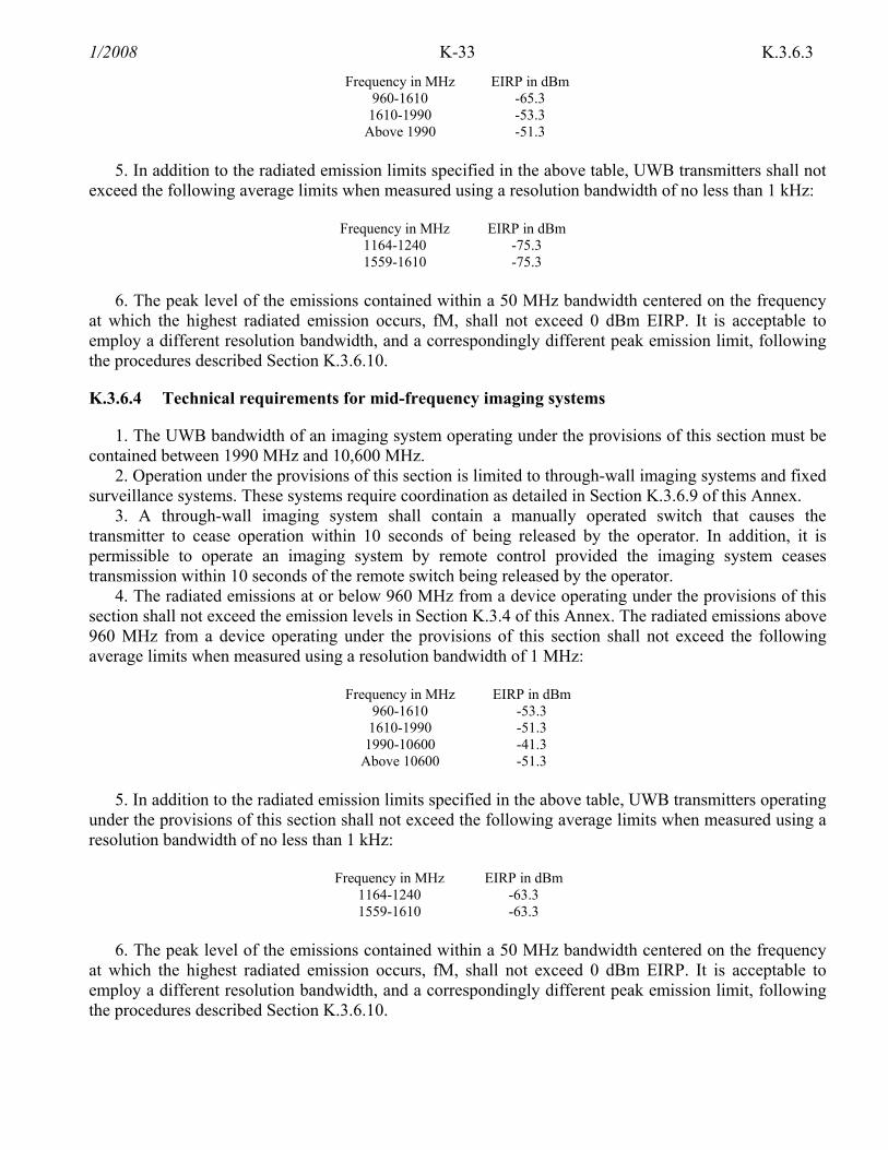
K-33 1/2008 K.3.6.3
Frequency in MHz EIRP in dBm 960-1610 -65.3
1610-1990 -53.3 Above 1990 -51.3
5. In addition to the radiated emission limits specified in the above table, UWB transmitters shall not
exceed the following average limits when measured using a resolution bandwidth of no less than 1 kHz:
Frequency in MHz EIRP in dBm 1164-1240 -75.3 1559-1610 -75.3
6. The peak level of the emissions contained within a 50 MHz bandwidth centered on the frequency
at which the highest radiated emission occurs, fM, shall not exceed 0 dBm EIRP. It is acceptable to employ a different resolution bandwidth, and a correspondingly different peak emission limit, following the procedures described Section K.3.6.10.
K.3.6.4 Technical requirements for mid-frequency imaging systems
1. The UWB bandwidth of an imaging system operating under the provisions of this section must be contained between 1990 MHz and 10,600 MHz.
2. Operation under the provisions of this section is limited to through-wall imaging systems and fixed surveillance systems. These systems require coordination as detailed in Section K.3.6.9 of this Annex.
3. A through-wall imaging system shall contain a manually operated switch that causes the transmitter to cease operation within 10 seconds of being released by the operator. In addition, it is permissible to operate an imaging system by remote control provided the imaging system ceases transmission within 10 seconds of the remote switch being released by the operator.
4. The radiated emissions at or below 960 MHz from a device operating under the provisions of this section shall not exceed the emission levels in Section K.3.4 of this Annex. The radiated emissions above 960 MHz from a device operating under the provisions of this section shall not exceed the following average limits when measured using a resolution bandwidth of 1 MHz:
Frequency in MHz EIRP in dBm
960-1610 -53.3 1610-1990 -51.3
1990-10600 -41.3 Above 10600 -51.3
5. In addition to the radiated emission limits specified in the above table, UWB transmitters operating
under the provisions of this section shall not exceed the following average limits when measured using a resolution bandwidth of no less than 1 kHz:
Frequency in MHz EIRP in dBm
1164-1240 -63.3 1559-1610 -63.3
6. The peak level of the emissions contained within a 50 MHz bandwidth centered on the frequency
at which the highest radiated emission occurs, fM, shall not exceed 0 dBm EIRP. It is acceptable to employ a different resolution bandwidth, and a correspondingly different peak emission limit, following the procedures described Section K.3.6.10.

K-34 1/2008K.3.6.5
K.3.6.5 Technical requirements for high frequency imaging systems
1. The UWB bandwidth of an imaging system operating under the provisions of this section must be contained between 3100 MHz and 10,600 MHz.
2. Operation under the provisions of this section is limited to GPRs and wall imaging systems and medical imaging systems used at the direction of, or under the supervision of, a licensed health care practitioner. The operation of these systems requires coordination, as detailed in Section K.3.6.9 of this Annex.
3. An imaging system shall contain a manually operated switch that causes the transmitter to cease operation within 10 seconds of being released by the operator. In addition, it is permissible to operate an imaging system by remote control provided the imaging system ceases transmission within 10 seconds of the remote switch being released by the operator.
4. The radiated emissions at or below 960 MHz from a device operating under the provisions of this section shall not exceed the emission levels in Section K.3.4 of this Annex. The radiated emissions above 960 MHz from a device operating under the provisions of this section shall not exceed the following average limits when measured using a resolution bandwidth of 1 MHz:
Frequency in MHz EIRP in dBm
960-1610 -65.3 1610-1990 -53.3 1990-3100 -51.3
3100-10600 -41.3 Above 10600 -51.3
5. In addition to the radiated emission limits specified in the above table, UWB transmitters operating
under the provisions of this section shall not exceed the following average limits when measured using a resolution bandwidth of no less than 1 kHz:
Frequency in MHz EIRP in dBm
1164-1240 -75.3 1559-1610 -75.3
6. The peak level of the emissions contained within a 50 MHz bandwidth centered on the frequency
at which the highest radiated emission occurs, fM, shall not exceed 0 dBm EIRP. It is acceptable to employ a different resolution bandwidth, and a correspondingly different peak emission limit, following the procedures described later in Section K.3.6.10.
K.3.6.6 Technical requirements for indoor UWB systems
1. Operation under the provisions of this section is limited to UWB transmitters employed solely for indoor operation.
a. Indoor UWB devices, by the nature of their design, must be capable of operation only indoors. The necessity to operate with a fixed indoor infrastructure, e.g., a transmitter that must be connected to the AC power lines, may be considered sufficient to demonstrate this.
b. The emissions from equipment operated under this section shall not be intentionally directed outside of the building in which the equipment is located, such as through a window or a doorway, to perform an outside function, such as the detection of persons about to enter a building.
c. The use of outdoor mounted antennas, e.g., antennas mounted on the outside of a building or on a telephone pole, or any other outdoors infrastructure is prohibited.

K-35 1/2008 K.3.6.6
d. Field disturbance sensors installed inside of metal or underground storage tanks are considered to operate indoors provided the emissions are directed towards the ground.
e. A communications system shall transmit only when the intentional radiator is sending information to an associated receiver.
2. The UWB bandwidth of a UWB system operating under the provisions of this section must be contained between 3100 MHz and 10,600 MHz.
3. The radiated emissions at or below 960 MHz from a device operating under the provisions of this section shall not exceed the emission levels in Section K.3.4 of this Annex. The radiated emissions above 960 MHz from a device operating under the provisions of this section shall not exceed the following average limits when measured using a resolution bandwidth of 1 MHz:
Frequency in MHz EIRP in dBm
960-1610 -75.3 1610-1990 -53.3 1990-3100 -51.3
3100-10600 -41.3 Above 10600 -51.3
4. In addition to the radiated emission limits specified in the above table, UWB transmitters operating
under the provisions of this section shall not exceed the following average limits when measured using a resolution bandwidth of no less than 1 kHz:
Frequency in MHz EIRP in dBm
1164-1240 -85.3 1559-1610 -85.3
5. The peak level of the emissions contained within a 50 MHz bandwidth centered on the frequency
at which the highest radiated emission occurs, fM, shall not exceed 0 dBm EIRP. It is acceptable to employ a different resolution bandwidth, and a correspondingly different peak emission limit, following the procedures described Section K.3.6.10.
6. UWB systems operating under the provisions of this section shall bear the following or similar statement in a conspicuous location on the device or in the instruction manual supplied with the device: "This equipment may only be operated indoors"
K.3.6.7 Technical requirements for handheld UWB systems
1. UWB devices operating under the provisions of this section must be hand held, i.e., they are relatively small devices that are primarily hand held while being operated and do not employ a fixed infrastructure.
a. A UWB device operating under the provisions of this section shall transmit only when it is sending information to an associated receiver. The UWB intentional radiator shall cease transmission within 10 seconds unless it receives an acknowledgment from the associated receiver that its transmission is being received. An acknowledgment of reception must continued to be received by the UWB intentional radiator at least every 10 seconds or the UWB device must cease transmitting.
b. The use of antennas mounted on outdoor structures, e.g., antennas mounted on the outside of a building or on a telephone pole, or any fixed outdoors infrastructure is prohibited. Antennas may be mounted only on the hand-held UWB device.
c. UWB devices operating under the provisions of this section may operate indoors or outdoors. 2. The UWB bandwidth of a device operating under the provisions of this section must be contained
between 3100 MHz and 10,600 MHz.

K-36 1/2008K.3.6.7
3. The radiated emissions at or below 960 MHz from a device operating under the provisions of this section shall not exceed the emission levels in Section K.3.4 of this Annex. The radiated emissions above 960 MHz from a device operating under the provisions of this section shall not exceed the following average limits when measured using a resolution bandwidth of 1 MHz:
Frequency in MHz EIRP in dBm
960-1610 -75.3 1610-1990 -63.3 1990-3100 -61.3 3100-10600 -41.3
Above 10600 -61.3 4. In addition to the radiated emission limits specified in the above table, UWB transmitters operating
under the provisions of this section shall not exceed the following average limits when measured using a resolution bandwidth of no less than 1 kHz:
Frequency in MHz EIRP in dBm
1164-1240 -85.3 1559-1610 -85.3
5. The peak level of the emissions contained within a 50 MHz bandwidth centered on the frequency
at which the highest radiated emission occurs, fM, shall not exceed 0 dBm EIRP. It is acceptable to employ a different resolution bandwidth, and a correspondingly different peak emission limit, following the procedures described Section K.3.6.10.
K.3.6.8 Technical requirements applicable to all UWB devices
1. Operation of UWB devices onboard an aircraft, a ship or a satellite is not prohibited. However, because of safety concerns, use by passengers aboard such vessels is prohibited. Moreover, UWB systems involving mission critical or safety of life services, which must be protected from other emitters, or involving aggregations of UWB devices aboard several mobile platforms cannot be operated under these provisions.
2. Digital circuitry that is used only to enable the operation of a transmitter and that does not control additional functions or capabilities is not classified as a digital device. Instead, the emissions from that digital circuitry are subject to the same limits as those applicable to the transmitter. If it can be clearly demonstrated that an emission from a UWB transmitter is due solely to emissions from digital circuitry contained within the transmitter and that the emission is not intended to be radiated from the transmitter's antenna, the limits shown in Section K.3.4 of this Annex shall apply to that emission rather than the limits specified in this section.
3. Within the tables in the above rule sections, the tighter emission limit applies at the band edges. Radiated emission levels at and below 960 MHz are based on measurements employing a CISPR quasi-peak detector. Radiated emission levels above 960 MHz are based on RMS average measurements over a 1 MHz resolution bandwidth. The RMS average measurement is based on the use of a spectrum analyzer with a resolution bandwidth of 1 MHz, an RMS detector, and a 1 millisecond or less averaging time. If pulse gating is employed where the transmitter is quiescent for intervals that are long compared to the nominal pulse repetition interval, measurements shall be made with the pulse train gated on.
4. The frequency at which the highest radiated emission occurs, fM, must be contained within the UWB bandwidth.
5. Imaging systems may be employed only for the type of information exchange described in their specific definitions contained earlier in this section. The detection of tags or the transfer or data or voice information is not permitted under the standards for imaging systems.
K-37 1/2008 K.3.6.8
6. When a peak measurement is required, it is acceptable to use a resolution bandwidth other than the 50 MHz specified in this subpart. This resolution bandwidth shall not be lower than 1 MHz or greater than 50 MHz, and the measurement shall be centered on the frequency at which the highest radiated emission occurs, fM. If a resolution bandwidth other than 50 MHz is employed, the peak EIRP limit shall be 20 log (RBW/50) dBm where RBW is the resolution bandwidth in megahertz that is employed. This may be converted to a peak field strength level at 3 meters using E(dBµV/m) = P(dBm EIRP) + 95.2.
7. The highest frequency employed in Section K.1.6 of this Annex to determine the frequency range over which radiated measurements are made shall be based on the center frequency, fC, unless a higher frequency is generated within the UWB device. For measuring emission levels, the spectrum shall be investigated from the lowest frequency generated in the UWB transmitter, without going below 9 kHz, up to the frequency range shown in Section K.1.6of this Annex or up to fC + 3/(pulse width in seconds), whichever is higher. There is no requirement to measure emissions beyond 40 GHz provided fC is less than 10 GHz; beyond 100 GHz if fC is at or above 10 GHz and below 30 GHz; or beyond 200 GHz if fC is at or above 30 GHz.
8. Agencies are reminded of the other standards and requirements in this Annex such as a limit on emissions conducted onto the AC power lines.
K.3.6.9 Coordination requirements
1. UWB imaging systems require coordination through the FAS before the equipment may be used. The operator shall comply with any constraints on equipment usage resulting from this coordination.
2. The users of UWB imaging devices shall supply detailed operational areas to NTIA. The information provided by the UWB operator shall include the name, address and other pertinent contact information of the user, the desired geographical area of operation, and the FCC ID number and other nomenclature of the UWB device.
3. Users of authorized, coordinated UWB systems may transfer them to other qualified users and to different locations upon coordination of change of ownership or location with the FAS and coordination with existing authorized operations.
4. The FAS coordination report shall include any needed constraints that apply to day-to-day operations. Such constraints could specify prohibited areas of operations or areas located near authorized radio stations for which additional coordination is required before operation of the UWB equipment. If additional local coordination is required, a local coordination contact will be provided.
K.3.6.10 Measurement Procedures
These measurement procedures are intended to provide general guidance for compliance measurements of UWB devices developed pursuant to Section 7.9 of this Manual. Except as otherwise described herein, measurements shall be made in accordance with the procedures specified in Part 15 of Title 47 of the Code of Federal Regulations.
a. Ground penetrating radars (GPRs) and wall imaging systems shall be tested under conditions that are representative of actual operating conditions. UWB devices intended for these types of application shall be compliance tested with the transducer at an operationally representative height above a twenty-inch thick bed of dry sand. The use of this medium, particularly for larger GPRs (e.g., those that are towed behind vehicles), will likely preclude the use of a turntable in the measurement procedure. For these cases, directionality gradients shall be analyzed and measurements shall be performed at a sufficient number of radials around the equipment under test to determine the radial at which the field strength values of the radiated emissions are maximized.
b. Field strength measurements of through-wall imaging systems may be made with a "thick gypsum or drywall board placed between the UWB device antenna and the measurement system antenna.

K-38 1/2008K.3.6.10
c. RMS average field strength measurements, required for all frequencies above 960 MHz, shall be made using techniques to obtain true RMS average. This can be accomplished by using a spectrum analyzer that incorporates a RMS detector. The resolution bandwidth of the analyzer shall be set to 1 MHz, the RMS detector selected, and a video integration time of 1 ms or less is to be used. If the transmitter employs pulse gating, in which the transmitter is quiescent for intervals that are long compared to the nominal pulse repetition interval, all measurements shall be made while the pulse train is gated on. Alternatively, a true RMS level can be measured using a spectrum analyzer that does not incorporate a RMS detector. This approach requires a multiple step technique beginning with a peak detection scan of the UWB spectrum with a RBW of 1 MHz and a VBW of no less than 1 MHz. The resulting trace is to be used to identify the frequency and bandwidth of the five highest peaks in the spectrum. The analyzer is then to be placed in a "zero span" mode, with a RBW of 1 MHz, a video bandwidth equal to or greater than 1 MHz, and a detector selected that does not distort or smooth the instantaneous signal levels (e.g., a "sample" detector). With these settings, a minimum of ten independent instantaneous points, representing the highest amplitude readings, are to be obtained during the time that a pulse is present, in each 1 MHz frequency bin across the bandwidth of each of the five highest peaks identified in the previous step. Note that when the PRF of the device under test is less than the measurement bandwidth of 1 MHz, a significant number of samples may be required to ensure that a minimum of 10 samples with the pulse present are obtained. The data obtained from these measurements must then be post-processed to determine true RMS average power levels. The post-processing of the data can be performed manually or with the aid of appropriate software.
d. On any frequency or frequencies below or equal to 960 MHz, the field strength shall be measured with equipment employing a CISPR quasi-peak detector function and related measurement bandwidths, unless otherwise specified.
e. In the frequency bands 1164-1240 MHz and 1559-1610 MHz, average radiated field strength measurements shall be made with a resolution bandwidth of no less than 1 kHz, using techniques as described previously for determining true RMS average power levels.
f. Peak radiated emission measurements shall be made using a spectrum analyzer with a 3 MHz resolution bandwidth and no less than a 3 MHz video bandwidth. The analyzer should be used in a maximum-hold trace mode. The peak power level expressed in a 3 MHz bandwidth and the frequency at which this level was measured shall be reported in the application for certification. A different resolution bandwidth between 1 MHz and 50 MHz may be employed with appropriate changes to the standard. If a resolution bandwidth greater than 3 MHz is employed, a detailed description of the test procedure, calibration of the test setup, and the instrumentation employed in the testing must be submitted to the Commission. It is recommended that measurements using a resolution bandwidth greater than 3 MHz be coordinated with the Commission's laboratory staff in advance of the submission for certification.
g. Field strength measurements may be performed without the use of a ground plane; however, a factor of 4.7 dB must be added to the measurement results thus obtained.
h. To the extent practicable, the device under test should be measured at the distance specified in the appropriate section of this Annex. However, in order to obtain an adequate signal-to-noise ratio in the measurement system, radiated measurements may have to be made at distances less than specified. In these cases, measurements may be performed at a distance other than what is specified, provided: measurements are not made in the near field of the measurement or device under test antenna, except where it can be shown that near field measurements are appropriate due to the characteristics of the device; and, it can be demonstrated that the signal levels necessitated a measurement at the distance employed in order to be accurately detected by the measurement equipment.
i. To the maximum extent possible, field strength measurements should be performed with the equipment under test positioned as it is intended to be used in actual operating conditions.

K-39 1/2008 K.3.6.10
j. Radiated field strength measurements must be made using the antenna to be employed with the UWB device under test. The measurement antenna must be sufficiently broad band to cover the frequency range of the measurements, and the use of multiple measurement antennas may be required. All measurement antennas used must be accurately calibrated and must demonstrate low phase dispersion over the frequency range of measurement. The orientation of the measurement antenna shall be varied to determine the polarization that maximizes the measured field strength.
k. The spectrum to be investigated should include at least the fundamental emission and the secondary lobe regardless of the center frequency. In order to accomplish this, the frequency spectrum shall be investigated from the lowest frequency generated within the device, without going below 9 kHz, up to the frequency range shown in Section K.1.6 of this Annex. up to an upper frequency defined by adding three divided by the pulse width in seconds to the center frequency in Hz, whichever is greater. The frequency range in Section K.1.6 is based on the center frequency unless a higher frequency, e.g., a carrier frequency, is generated within the device. There is no requirement to measure emissions beyond 40 GHz provided the center frequency is less than 10 GHz; beyond 100 GHz if the center frequency is at or above 10 GHz and below 30 GHz; or beyond 200 GHz if the center frequency is at or above 30 GHz.
K.4 CONVERSION FORMULAS
To convert from EIRP (i.e., product of the power supplied to the antenna and the antenna gain) values to field strength use the formula:
R
GPE tt
2/1)30( ××=
where:
E = Field Strength, V/m P = Power supplied to the antenna, watts G = Numerical antenna gain ratio relative to isotropic at the given frequency R = Distance, meters
This formula assumes wave spreading (i.e., "free-space") losses only. The power supplied to the antenna is the transmitter output power less any line losses. In most cases,
the line losses for these devices are difficult to quantify. Example: Determine if a field disturbance sensor operating at a frequency of 915 MHz with a power
output of 1 mW, no line losses and an antenna gain of 3 dBi meets the field strength criterion in Section K.3.5.16 of this Annex.
Step 1: Convert the decibel antenna gain to a numerical ratio. Numerical gain ratio = 10 (decibel value/10) = 10 (3/10) = 2

K-40 1/2008K.4
Step 2: Use the EIRP to field intensity conversion formula.
3
)2001.030( 2/1××=E
E=0.0816 V/m = 81,600 µV/m Since the criterion is 500,000 µV/m at 3m, the device meets the indicated criterion in Section
K.3.5.16 and can be operated without further authority from the Assistant Secretary as indicated in Section 7.9 of this manual.
K.5 CROSS-REFERENCE OF NON-LICENSE DEVICE STANDARDS IN ANNEX K AND THOSE IN THE FCC CFR 47 PART 15.
ANNEX K NUMBER PART 15 NUMBER
K.1 Introduction N/A K.1.1 Definitions (some new definitions) 15.3 K.1.2 Incidental Radiators 15.13 – 15.15 K.1.3 Susceptibility to Interference 15.17 K.1.4 Labeling Requirements 15.19 K.1.5 Emission Limits 15.35 K.1.6 Frequeny Range and Distance Extrapolation of Radiated Measurements 15.31 and 15.33 K.2 Unintentional Radiators N/A K.2.1 Conducted Limits 15.107 K.2.2 Radiated Emission Limits 15.109 K.3 Intentional Radiators N/A K.3.1 Antenna Requirements 15.203 K.3.1.1 External Radio Frequency Power Amplifiers and Antenna Modifications 15.204 K.3.2 Restricted Bands of Operation 15.205 K.3.3 Conducted Limits 15.207 K.3.4 Radiation Emission Limits, General Requirements 15.209 K.3.5 Radiation Emission Limits, Additional Provisions N/A K.3.5.1 Additional Provisions to the General Radiation Limits 15.215 K.3.5.2 Operation in the Band 160-190 kHz 15.217 K.3.5.3 Operation in the Band 510-1705 kHz 15.219 K.3.5.4 Operation in the Band 525-1705 kHz 15.221 K.3.5.5 Operation in the Band 1.705-10 MHz 15.223 K.3.5.6 Operation in the Band 13.553-13.567 MHz 15.225 K.3.5.7 Operation in the Band 26.96-27.28 MHz 15.227 K.3.5.8 Operation in the Band 40.66-40.70 MHz 15.229 K.3.5.9 Periodic Operation in the Band 40.66-40.70 MHz and above 70 MHz 15.231 K.3.5.10 Operation in the Bands 46.60-46.98 and 49.66-50.00 MHz 15.233 K.3.5.11 Operation in the Band 49.82-49.90 MHz 15.235 K.3.5.12 Operation in the Bands 72.0-73.0 and 75.4-76.0 MHz 15.237 K.3.5.13 Operation in the Band 88-108 MHz 15.239 K.3.5.14 Operation in the Band 174-216 MHz 15.241 K.3.5.15 Operation in the Band 890-940 MHz 15.243 K.3.5.16 Operation in the Bands 902-928, 2435-2465, 5785-5815, 10500-10550, and 24075-24175 MHz
15.245
K.3.5.17 Operation in the Bands 902-928, 2400-2483.5, and 5725-5850 MHz 15.247 K.3.5.18 Operation in the Bands 902-928, 2400-2483.5, 5725-5875 MHz and 24.0-24.25 GHz 15.249 K.3.5.19 Operation in the Bands 2.9-3.26, 3.267-3.332, 3.339-3.458, and 3.358-3.6 GHz 15.251 K.3.5.20 Unlicensed National Information Infrastructure (U-NII) Devices N/A
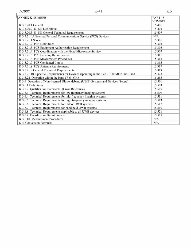
K-41 1/2008
K.5
ANNEX K NUMBER PART 15 NUMBER
K.3.5.20.1 General 15.401 K.3.5.20.2 U- NII Definitions 15.403 K.3.5.20.3 U- NII General Technical Requirements 15.407 K.3.5.21 Unlicensed Personal Communications Service (PCS) Devices N/A K.3.5.21.1 Scope 15.301 K.3.5.21.2 PCS Definitions 15.303 K.3.5.21.3 PCS Equipment Authorization Requirement 15.305 K.3.5.21.4 PCS Coordination with the Fixed Microwave Service 15.307 K.3.5.21.5 PCS Labeling Requirements 15.311 K.3.5.21.6 PCS Measurement Procedures 15.313 K.3.5.21.7 PCS Conducted Limits 15.315 K.3.5.21.8 PCS Antenna Requirements 15.317 K.3.5.21.9 General Technical Requirements 15.319 K.3.5.21.10 Specific Requirements for Devices Operating in the 1920-1930 MHz Sub-Band 15.323 K.3.5.22 Operation within the band 57-64 GHz 15.255 K.3.6 Operation of Non-licensed Ultrawideband (UWB) Systems and Devices (Scope) 15.501 K.3.6.1 Definitions 15.503 K.3.6.2 Qualification statements (Cross Reference) 15.505 K.3.6.3 Technical Requirements for low frequency imaging systems 15.509 K.3.6.4 Technical Requirements for mid-frequency imaging systems 15.511 K.3.6.5 Technical Requirements for high frequency imaging systems 15.513 K.3.6.6 Technical Requirements for indoor UWB systems 15.517 K.3.6.7 Technical Requirements for hand held UWB systems 15.519 K.3.6.8 Technical Requirements applicable to all UWB devices 15.521 K.3.6.9 Coordination Requirements 15.525 K.3.6.10 Measurement Procedures N/A K.4 Conversion Formulas N/A

K-42 1/2008
(Last Page in Annex K)