Technical Speci˜cations and Wiring Diagrams
3
Cumberland: http://www.cumberlandpoultry.com AP: http://www.automatedproduction.com GSI Electronics Inc. • 5200 Armand Frappier Saint-Hubert, Qc • Canada J3Z 1G5 • Phone: 1-877-926-2777 E-mail: [email protected] REV 03 WIRING DIAGRAM Agri Alert KP-8IN,TP-8IN,TR-2IN #891-00518 REV 03 Please scan the QR Code to access the complete manual or visit the website. EN Technical Specifications and Wiring Diagrams KP-8IN-1REL Weight TP-8IN-1REL Weight TR-8IN-1REL Weight Height 178 mm (7 inches) Width 229 mm (9 inches) Depth 76.2 mm (3 inches) Top 152mm (6 inches) Bottom 152mm (6 inches) Sides 152mm (6 inches) Weight and Dimensions 861,83 grams (1.90 lbs) 861,83 grams (1.90 lbs) 816.47 grams (1.80 lbs) Enclosure dimensions Clearance around the enclosure Protocol Handling Output Power System Clock Frequency Output Equipment type (ETSI EN 301 489-3) III Others : Identification/Access control Class type (ETSI EN 301 489-3) 2 (Medium reliable SRD communication media; e.g. causing inconvenience to persons, which cannot simply be overcome by other means) Telecommunica�on Ra�ngs for RFID Module (Only on KP-8IN-1REL and TR-2IN-1REL) ISO15693 +20 dBm (100 mW) 13.56MHz KP-8IN-1REL Supply Input 24/28Vdc, 5.62W TP-8IN-1REL Supply Input 24/28Vdc, 4.72W TR-2IN-1REL Supply Input 24/28Vdc, 4.3W 5 A MAX (Nb of Units = Max current rating divide by the max current of the fan multiply by its service factor will give you the number of this fan type the relay can drive) For example, 5A / (2.5 A * 1.5 SF) = 1.3, relay can drive up to 1 fan Minimum load of 0.2A 50/60Hz 120Vac ,1/6HP (124W) Resistive loads (electric heating element) 150Vac Max. / 28/24 VAC/DC, 5A max. Minimum load of 0.2A 120 Vac, 2A max. Minimum load of 0.2A 24Vdc, 5A max. (The current reading is not available in DC) (Minimum load of 0.2A ) Safety Ra�ngs Inputs: Outputs: Motor/inductive loads Tungsten loads loads (incandescent and heat lamp) DC loads Compliant to GSIE temperature probes, Accuracy of ±0.1ºC in a normal operation, Allowable loss of performance in a noisy environment: Accuracy of ±0.65ºC from initial reading with a fixed resistor of 1% precision used for testing purpose. Sensor must be able to drive a 2k Ohms load, which means the sensor must drive at least 2.5mA to ensure correct readings. Accuracy of ±30mV in a normal operation, Allowable loss of performance in a noisy environment: Accuracy of ±80mV from initial reading with a voltage source of 1% precision used for testing purpose. Sensor must be able to drive a 120 Ohms load Maximum rating: 20.8mA, 2.5V Accuracy of ±0.2mA in a normal operation Allowable loss of performance in a noisy environment: Accuracy of ±0.4mA from initial reading with a current source of 1% precision used for testing purpose. Close contact resistance must be lower than 200 Ohms Open contact resistance must be higher than 100k Ohms Max 100Hz, pulse width minimum of 3.2ms Max 100 Ohms (close contact) and min. 100k Ohms (open contact) including the value of the wire resistance Accuracy of ±0.5A for AC load <5A in a normal environment Allowable loss of performance in a noisy environment: Accuracy of ±0.75A from initial reading with a load of 1% precision used for testing purpose 24Vdc 24 Vdc, 50 mA max Operating Temperature -20 to 40°C (-4 to 104°F) Storage Temperature -40 to 50°C (-40 to 122°F) Environment Type Indoor and outdoor use Pollution Degree 2 Installation Category 2 Altitude 2000 Meters Max. (6561 Ft. Max) -40 to 0°C (-40 to 32°F) Non condensing 0 to 10°C (32 to 50°F) Non condensing 10 to 30°C (50 to 86°F) 95 % (± 3 %) Non condensing 30 to 40°C (86 to 104°F) 95 % (± 3 %) Non condensing IP rating (IEC 60529) 66 Nema Rating (Nema 250) 4X Flame Rating (UL94) 5VA V-0 Flame Rating (IEC 60695 or IEC 60707) FV-0 IK rating (degree of mechanical protection - impact, IEC 62262) 8 Relay outputs with current sensing input Outputs: Operational ratings Operating Relative Humidity (maximum) Func�onal Ra�ngs Inputs: Temperature Analog 0-5 Volts Analog 4-20mA Dry contact Water meter, Pulse speed
Transcript of Technical Speci˜cations and Wiring Diagrams

Cumberland: http://www.cumberlandpoultry.comAP: http://www.automatedproduction.com
GSI Electronics Inc. • 5200 Armand Frappier Saint-Hubert, Qc • Canada J3Z 1G5 • Phone: 1-877-926-2777 E-mail: [email protected]
REV 03
WIRING DIAGRAM
Agri Alert KP-8IN,TP-8IN,TR-2IN
#891-00518 REV 03
Please scan the QR Code to access the complete manual or visit the website.
EN
Technical Specications and Wiring Diagrams
KP-8IN-1REL WeightTP-8IN-1REL WeightTR-8IN-1REL Weight
Height 178 mm (7 inches)Width 229 mm (9 inches)Depth 76.2 mm (3 inches)Top 152mm (6 inches)Bottom 152mm (6 inches)Sides 152mm (6 inches)
Weight and Dimensions861,83 grams (1.90 lbs)861,83 grams (1.90 lbs)816.47 grams (1.80 lbs)
Enclosure dimensions
Clearance around the enclosure
Protocol Handling
Output Power
System Clock Frequency Output
Equipment type (ETSI EN 301 489-3) III Others : Identification/Access control
Class type (ETSI EN 301 489-3) 2
(Medium reliable SRD communication media; e.g. causing inconvenience to persons, which cannot simply be overcome by other means)
Telecommunicaon Rangs for RFID Module (Only on KP-8IN-1REL and TR-2IN-1REL)
ISO15693
+20 dBm (100 mW)
13.56MHz
KP-8IN-1REL Supply Input 24/28Vdc, 5.62W
TP-8IN-1REL Supply Input 24/28Vdc, 4.72W
TR-2IN-1REL Supply Input 24/28Vdc, 4.3W
5 A MAX
(Nb of Units = Max current rating divide by the max current of the fan multiply by its service factor will give you the number of this fan type the relay can drive)
For example, 5A / (2.5 A * 1.5 SF) = 1.3, relay can drive up to 1 fan Minimum load of 0.2A50/60Hz 120Vac ,1/6HP (124W)
Resistive loads (electric heating element)
150Vac Max. / 28/24 VAC/DC, 5A max. Minimum load of 0.2A120 Vac, 2A max.Minimum load of 0.2A
24Vdc, 5A max.(The current reading is not available in DC) (Minimum load of 0.2A )
Safety RangsInputs:
Outputs:
Motor/inductive loads
Tungsten loads loads (incandescent and heat lamp)
DC loads
Compliant to GSIE temperature probes, Accuracy of ±0.1ºC in a normal operation, Allowable loss of performance in a noisy environment:Accuracy of ±0.65ºC from initial reading with a fixed resistor of 1% precision used for testing purpose.Sensor must be able to drive a 2k Ohms load, which means the sensor must drive at least 2.5mA to ensure correct readings. Accuracy of ±30mV in a normal operation,Allowable loss of performance in a noisy environment:Accuracy of ±80mV from initial reading with a voltage source of 1% precision used for testing purpose.Sensor must be able to drive a 120 Ohms load Maximum rating: 20.8mA, 2.5VAccuracy of ±0.2mA in a normal operationAllowable loss of performance in a noisy environment:Accuracy of ±0.4mA from initial reading with a current source of 1% precision used for testing purpose.Close contact resistance must be lower than 200 OhmsOpen contact resistance must be higher than 100k Ohms
Max 100Hz, pulse width minimum of 3.2msMax 100 Ohms (close contact) and min. 100k Ohms (open contact) including the value of the wire resistanceAccuracy of ±0.5A for AC load <5A in a normal environment Allowable loss of performance in a noisy environment:Accuracy of ±0.75A from initial reading with a load of 1% precision used for testing purpose
24Vdc 24 Vdc, 50 mA max
Operating Temperature -20 to 40°C (-4 to 104°F)
Storage Temperature -40 to 50°C (-40 to 122°F)
Environment Type Indoor and outdoor use
Pollution Degree 2
Installation Category 2
Altitude 2000 Meters Max. (6561 Ft. Max)-40 to 0°C (-40 to 32°F) Non condensing 0 to 10°C (32 to 50°F) Non condensing10 to 30°C (50 to 86°F) 95 % (± 3 %) Non condensing30 to 40°C (86 to 104°F) 95 % (± 3 %) Non condensing
IP rating (IEC 60529) 66
Nema Rating (Nema 250) 4X
Flame Rating (UL94) 5VA V-0
Flame Rating (IEC 60695 or IEC 60707) FV-0IK rating (degree of mechanical protection - impact, IEC 62262) 8
Relay outputs with current sensing input
Outputs:
Operational ratings
Operating Relative Humidity (maximum)
Funconal RangsInputs:
Temperature
Analog 0-5 Volts
Analog 4-20mA
Dry contact
Water meter, Pulse speed

WIRING DIAGRAM
Agri Alert KP-8IN,TP-8IN,TR-2IN
#891-00518 REV 03
EN
Rules:• The cable’s shield can only be connected to EARTH at one end.• Safety communication bus is not used with AA128.• END of LINE must be disabled. • Maximum load on SBI is 2A, see Power Table to determine the maximum number of units the AA128 can power.
Distance Mim. Wire Gage150 m (500 .) 18 AWG300 m (1000 .) 16 AWG*600 m (2000 .) 14 AWG900 m (3000 .) 12 AWG1200 m (4000 .) 10 AWG* Recommended
Power Cable
Wire Color Color CodeRed RDBlue BL*Black BKWhite WHOrange ORYellow YLGreen/Yellow GN/YL
*BL could be Green instead of Blue.
COMMUNICATION WIRING
1 2 3
4
65
DAISY CHAIN TOPOLOGY
OK
1 2 3
4
65
NO
STAR TOPOLOGY
Module Power Load on 24VDCTR-2IN-1REL 4.3 W 180 mATP-8IN-1REL 4.7 W 196 mAKP-8IN-1REL 5.6 W 233 mA
POWER
Communication 1200 m (4000 ft) max18 AWG twisted pair shielded cable
Terminals A & B
Power 300 m (1000 ft) with 16 AWG *
1 pair used for Power (24 & GND)The other pair used for Communication (A & B)
...
BASE BOARDAA128
PVX (SW1)EOL
Enabled
A B GN
D
SBI
1 2 3 4
PVX
24V
A B GN
D
Comm/Power Port
24V
A B GN
D
AUTOMATION SAFETY
PCB-434
End Of Line Auto
EOL
End Of LineSafety
EOL
KP-8IN-1RELTP-8IN-1RELTR-2IN-1REL
Unit 1
24V
A B GN
D
Comm/Power Port
24V
A B GN
D
AUTOMATION SAFETY
PCB-434
End of LineAuto Enabled
EOL
End Of LineSafety
EOL
KP-8IN-1RELTP-8IN-1RELTR-2IN-1REL
Refer to SectionGrounding recommendations for
the system in the Instruction Manual
Unit n
Safety / AutomaonCommunicaon Port
Internal connecon
24V
A B GN
D
2 x shielded twisted pairs18 AWG (min.), 600V, 90C (min.)Recommended cable type: TC-ER/CIC
RDRD
RDRD
RDRDBKBK
BKBK
BKBKBLBL
BLBL
BLBLGRGR
GRGR
GRGR RDRD BKBKBLBL GRGRGRGR GRGR
IN GN
DIN G
ND
IN GN
DIN G
ND
Inside or Outside Temperature Probe
IN GN
DIN G
ND
IN GN
DIN G
ND
Normally open circuit without EOLR
Normally closed circuit with EOLR
Normally closed circuit without EOLR
Normally open circuit with EOLR
1.5KΩ , ½W
1.5KΩ , ½W
1.5KΩ , ½W1.5KΩ , ½W
1.5KΩ , ½W
1.5KΩ , ½W
1.5KΩ , ½W
1.5KΩ , ½WNormally opened circuit with double EOLR
Normally closed circuit with double EOLR
Watermeter
IN GN
D IN5
GN
D5
IN7
GN
D7
IN1
GN
D1
IN3
GN
D3
IN6
GN
D6
IN8
GN
D8
IN2
GN
D2
IN4
GN
D4
T°
NO
CO
MN
C
RELAY
Static pressure or humidity sensor
24V
OU
T
OUT+4-20mA
SENSOR
NO
CO
MN
C
RELAY
NO
CO
MN
C
RELAY
OR
L1
L2/N
FANALARM HEATERLIGHTFAN ALARMHEATERLIGHT
From electricaldistribution panel
L2/N
L1
24V
OU
T
24V
OU
T
From electricaldistribution panel
Power Supply and Communication Scheme in an AA128 Touch System
Analog Inputs Scheme Relay Output Scheme
2 x shielded twisted pairs18 AWG (min.), 600V, 90C (min.)Recommended cable type: TC-ER/CIC
WIRING DIAGRAM
Agri Alert KP-8IN,TP-8IN,TR-2IN
#891-00518 REV 03
EN
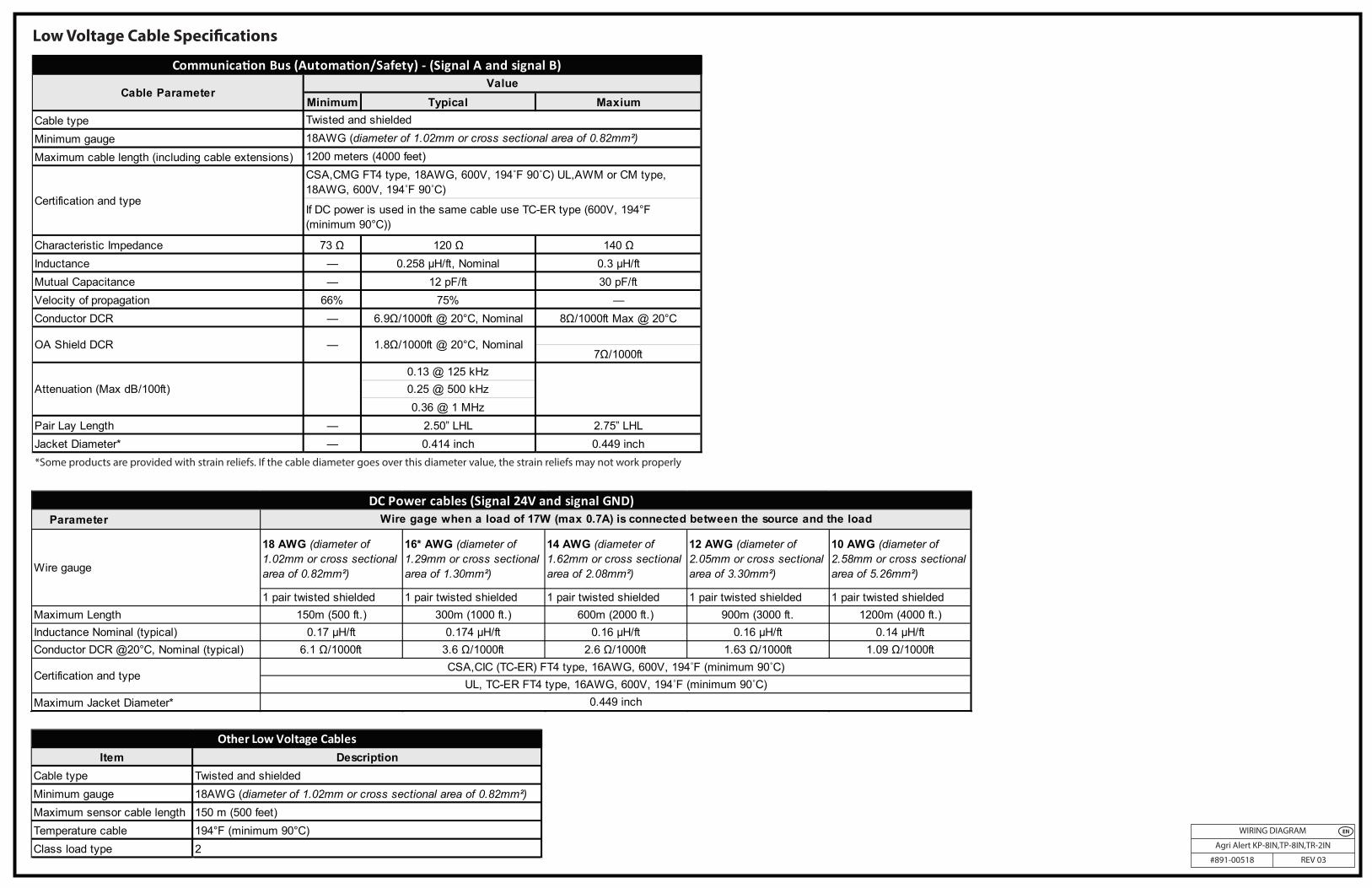
Parameter
18 AWG (diameter of 1.02mm or cross sectional area of 0.82mm²)
16* AWG (diameter of 1.29mm or cross sectional area of 1.30mm²)
14 AWG (diameter of 1.62mm or cross sectional area of 2.08mm²)
12 AWG (diameter of 2.05mm or cross sectional area of 3.30mm²)
10 AWG (diameter of 2.58mm or cross sectional area of 5.26mm²)
1 pair twisted shielded 1 pair twisted shielded 1 pair twisted shielded 1 pair twisted shielded 1 pair twisted shieldedMaximum Length 150m (500 ft.) 300m (1000 ft.) 600m (2000 ft.) 900m (3000 ft. 1200m (4000 ft.)Inductance Nominal (typical) 0.17 μH/ft 0.174 μH/ft 0.16 μH/ft 0.16 μH/ft 0.14 μH/ftConductor DCR @20°C, Nominal (typical) 6.1 Ω/1000ft 3.6 Ω/1000ft 2.6 Ω/1000ft 1.63 Ω/1000ft 1.09 Ω/1000ft
Maximum Jacket Diameter*
DC Power cables (Signal 24V and signal GND)
Certification and typeCSA,CIC (TC-ER) FT4 type, 16AWG, 600V, 194˚F (minimum 90˚C)
UL, TC-ER FT4 type, 16AWG, 600V, 194˚F (minimum 90˚C)0.449 inch
Wire gage when a load of 17W (max 0.7A) is connected between the source and the load
Wire gauge
Minimum Typical MaxiumCable typeMinimum gaugeMaximum cable length (including cable extensions)
Characteristic Impedance 73 Ω 120 Ω 140 ΩInductance — 0.258 µH/ft, Nominal 0.3 µH/ftMutual Capacitance — 12 pF/ft 30 pF/ftVelocity of propagation 66% 75% —Conductor DCR — 6.9Ω/1000ft @ 20°C, Nominal 8Ω/1000ft Max @ 20°C
7Ω/1000ft0.13 @ 125 kHz0.25 @ 500 kHz0.36 @ 1 MHz
Pair Lay Length — 2.50” LHL 2.75” LHLJacket Diameter* — 0.414 inch 0.449 inch
Communicaon Bus (Automaon/Safety) - (Signal A and signal B)
OA Shield DCR — 1.8Ω/1000ft @ 20°C, Nominal
Attenuation (Max dB/100ft)
Value
Twisted and shielded18AWG (diameter of 1.02mm or cross sectional area of 0.82mm²)1200 meters (4000 feet)
Certification and type
CSA,CMG FT4 type, 18AWG, 600V, 194˚F 90˚C) UL,AWM or CM type, 18AWG, 600V, 194˚F 90˚C)
If DC power is used in the same cable use TC-ER type (600V, 194°F (minimum 90°C))
Cable Parameter
*Some products are provided with strain reliefs. If the cable diameter goes over this diameter value, the strain reliefs may not work properly
Low Voltage Cable Specications
Item DescriptionCable type Twisted and shieldedMinimum gauge 18AWG (diameter of 1.02mm or cross sectional area of 0.82mm²)Maximum sensor cable length 150 m (500 feet)Temperature cable 194°F (minimum 90°C)Class load type 2
Other Low Voltage Cables