Technical Speci cations - napoleonproducts.com
8
W415-1180 / A / 03.22.13 C92 SERIES (CBM) Continental® Single Stage, Multi Speed PSC, Condensing Multi Position Gas Furnace Up to 94.0% AFUE Certified through AHRI Input 30,000 - 120,000 Btuh Technical Specifications PRESIdEnT’S lIMITEd WARRAnTY (Registered) To the original registered owner and his or her spouse (“owner”), the hEAT EXChAngER* is warranted for 20 YEARS in the home which the unit was originally installed, and all remaining parts as warranted for a period of 10 YEARS, except as provided below. These warranties apply only if: • The unit is installed in an owner-occupied, primary single family residence, and • The unit is properly registered with Continental® online within 60 days after the original installation. To register, go to www.continentalheatingandcooling.com. Some states and provinces do not allow limitations on how long an implied limited warranty lasts or do not allow the exclusion or limitation of incidental or consequential damages, so the above limitation or exclusion may not apply to you. This limited warranty gives you specific legal rights, and you may also have other rights which vary by jurisdiction. OR lIMITEd WARRAnTY (Not Registered) If not registered within 60 days, the hEAT EXChAngER is warranted for a period of 20 YEARS (pro rated), and all internal functional parts are warranted for a period of 5 YEARS, all other limitations apply. • Furnace is less than 33” (838 mm) tall! • Multi Speed PSC Blower Motor • T140 Aluminized Wrinkle Bent Primary Heat Exchanger Tubes • 29-4C Stainless Steel Heat Recovery Coil • Aluminized Multi-Port In-Shot Burners • Self Diagnostic Integrated Furnace Control • Thermally Insulated Cabinet • Zero clearance in all positions • Direct and Single Vent installation approved • One LP Conversion Kit • Certified to 4500 ft (1372 m) in Canada • 100% Units factory fired and safety tested • Internal Condensate Trap • Clear Front Manifold Cover • Easy Blower removal • Sealed Vestibule and Blower Compartments for quiet operation • Concentric Venting Approved C B M 030 S 2 A Continental Gas Furnace B = Builders S = Standard P = Premium U = Ultimate M = Multi Speed X = X13 DC Drive V = ECM 2.3 Design Level Airflow Tonnage 2 = 2 Tons 3 = 3 Tons 4 = 4 Tons 5 = 5 Tons S = Single Stage T = Two Stage Input Capacity 030 = 30,000 Btuh 040 = 40,000 Btuh 060 = 60,000 Btuh 080 = 80,000 Btuh 100 = 100,000 Btuh 120 = 120,000 Btuh Annual Fuel Utilization Efficiency (AFUE) Gas- or Propane-fired forced-air furnace with a high efficiency motor 98% 90% 92.1 - 94.0 The C92 Series High Efficiency Gas Furnace may be installed in three positions, alcove or closet installations that require zero clearance. Certified by CSA for application in Canada and the United States. WARRANTY FEATURES AND BENEFITS MODEL BREAKDOWN
Transcript of Technical Speci cations - napoleonproducts.com
W415-1180 / A / 03.22.13
1
C92 SERIES (CBM)Continental® Single Stage, Multi Speed PSC, Condensing Multi Position Gas FurnaceUp to 94.0% AFUE Certified through AHRIInput 30,000 - 120,000 Btuh
Technical Speci� cations
CONTINENTAL® C92 GAS FURNACE PRESIDENT’S LIMITED LIFETIME WARRANTY
Continental® products are designed with superior components and materials, assembled by trained craftsmen who take great pride in their work. The complete appliance is again thoroughly inspected by a qualifi ed technician before packaging to ensure that you, the customer, receives the quality product that you expect from Continental®.
This heating unit is warranted by Wolf Steel Ltd. (“Continental®”) to be free from defects in materials and workmanship under normal use and maintenance.
PRESIdEnT’S lIMITEd WARRAnTY (Registered)To the original registered owner and his or her spouse (“owner”), the hEAT EXChAngER* is warranted for 20 YEARS in the home which the unit was originally installed, and all remaining parts as warranted for a period of 10 YEARS, except as provided below. These warranties apply only if:• The unit is installed in an owner-occupied, primary single family
residence, and• The unit is properly registered with Continental® online within 60
days after the original installation. To register, go to www.continentalheatingandcooling.com. Some states and provinces do not allow limitations on how long an implied limited warranty lasts or do not allow the exclusion or limitation of incidental or consequential damages, so the above limitation or exclusion may not apply to you. This limited warranty gives you specifi c legal rights, and you may also have other rights which vary by jurisdiction.
ORlIMITEd WARRAnTY (Not Registered)
If not registered within 60 days, the hEAT EXChAngER is warranted for a period of 20 YEARS (pro rated), and all internal functional parts are warranted for a period of 5 YEARS, all other limitations apply.
Proof of purchase will be required. Replacements are subject to review and verifi cation by a Continental® representative.
Warranty ceases to exist if the unit is removed from the location where it was originally installed.
This limited warranty will not apply unless the gas furnace is: (1) installed by a licensed or qualifi ed HVAC technician, (2) installed in accordance with the manufacturer’s recommendations in its Installation and Operation Manual, and (3) in compliance with all industry standards, national, provincial/state, and local codes.
Regardless of time of registration, the warranty period begins on the date of the original installation. Where a product is installed in a newly constructed home; the date of installation is the date the homeowner takes possession of the home from the builder. If that date cannot be verifi ed, the warranty period begins three months after the month of manufacture (indicated by the fi rst four digits of the serial number.
As its only responsibility, and your only remedy, Continental® will furnish a replacement part, without charge for the part only, to replace any part that is found to be defective due to workmanship or materials under normal use and maintenance.
To make a warranty claim, the defective part must be returned to a Continental® heating and air conditioning products dealer/distributor by a certifi ed or licensed contractor. Any part replaced pursuant to this warranty is warranted only for the unexpired portion of the warranty term applying to the original part.
These warranties do not apply to labour, freight, or any other cost associated with the service, repair or operation of the unit, and diagnostic costs.
Continental® is not responsible for:
1. Cost or expenses incurred as a consequence of a faulty installation or application.
2. Damage or repairs required as a consequence of faulty installation or application.
3. Damages, defects or failures caused by installation that is not performed in compliance with all applicable federal, provincial, state laws or regulations, and Installation Operating Manual.
4. Damage as a result of vandalism, freight damage, fl oods, fi res, winds, lightning, and accidents, or any acts of nature. Atmospheres contaminated by compounds of chlorine, halogenated hydrocarbons, or other damaging chemicals causing deterioration of components, or other conditions beyond the control of Continental®.
5. Use of components or accessories not compatible with this unit.6. Products installed outside Canada, or the United States and its
territories.7. Routine maintenance, but not limited to, cleaning of the coils,
fi lter cleaning and/or replacement and lubrication.8. Parts not supplied by Continental®.9. If unit is equipped with n ultraviolet bulb, the bulb is warranted for
90 days from date of install.10. Damage or repairs required as a result of any improper use,
maintenance, operation,servicing, cleaning or replacing air fi lters.11. Failure to operate due to interruption and/or inadequate electrical
service.12. Damages, defects or failures caused by accidents or negligent or
unreasonable use or operation of the unit and its’ components, including without limitation, operation beyond rated capacity and operation of electrical components at voltage other than that specifi ed on the rating plate.
13. Continental® shall not in any event extend warranty coverage to any incidental, consequential or indirect damages.
14. Changes in the appearance of the unit that do not affect its performance.
15. Damages, defects or failures caused by operation of the unit in abnormal environmental conditions (i.e. salt air).
16. Damages, defects or failures caused by conditioned air (return air) supplied to the furnace being greater than 20% from out-of-doors (13°C/55°F min. return air temperature).
17. Damages, defects or failures caused by the furnace being installed downstream from a cooling coil.
* “Heat Exchanger” means the primary combustion heat exchanger for the gas furnace and the secondary or tertiary heat exchanger. The plastic front manifold condensate collector attached to the secondary or tertiary heat exchanger is not considered part of the heat exchanger.
For further information about this warranty, contact Continental® Technical Service Department at (866) 539-2039, email [email protected], or by mail to , 24 Napoleon Road, Barrie, Ontario L4M 0G8 Canada
www.continentalheatingandcooling.com
Dealer NameDealer’s City/Province-State/Postal-Zip Code
Telephone/Fax E-mail Address
Model and Serial Number (Serial number located on inside bottom door)
Installation Date
12.05.12
FOR HOMEOWNERS FUTURE REFERENCE
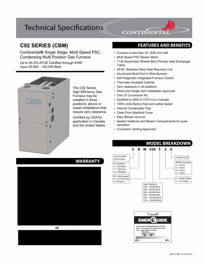
• Furnace is less than 33” (838 mm) tall!• Multi Speed PSC Blower Motor• T140 Aluminized Wrinkle Bent Primary Heat Exchanger
Tubes• 29-4C Stainless Steel Heat Recovery Coil• Aluminized Multi-Port In-Shot Burners• Self Diagnostic Integrated Furnace Control• Thermally Insulated Cabinet• Zero clearance in all positions• Direct and Single Vent installation approved• One LP Conversion Kit• Certified to 4500 ft (1372 m) in Canada• 100% Units factory fired and safety tested• Internal Condensate Trap• Clear Front Manifold Cover• Easy Blower removal• Sealed Vestibule and Blower Compartments for quiet
operation• Concentric Venting Approved
C B M 030 S 2 A
ContinentalGas Furnace
B = BuildersS = StandardP = PremiumU = Ultimate
M = Multi SpeedX = X13 DC DriveV = ECM 2.3
Design Level
Air�ow Tonnage2 = 2 Tons3 = 3 Tons4 = 4 Tons5 = 5 Tons
S = Single StageT = Two Stage
Input Capacity030 = 30,000 Btuh040 = 40,000 Btuh060 = 60,000 Btuh080 = 80,000 Btuh100 = 100,000 Btuh120 = 120,000 Btuh
Annual Fuel Utilization Efficiency (AFUE)Gas- or Propane-fired forced-air furnacewith a high efficiency motor
98%90%
92.1 - 94.0
The C92 Series High Efficiency Gas Furnace may be installed in three positions, alcove or closet installations that require zero clearance.Certified by CSA for application in Canada and the United States.
WARRANTY
FEATURES AND BENEFITS
MODEL BREAKDOWN
W415-1180 / A / 03.22.13
2
1 211
12
1918
17
16
15
1413
354
6
7
89
10
7
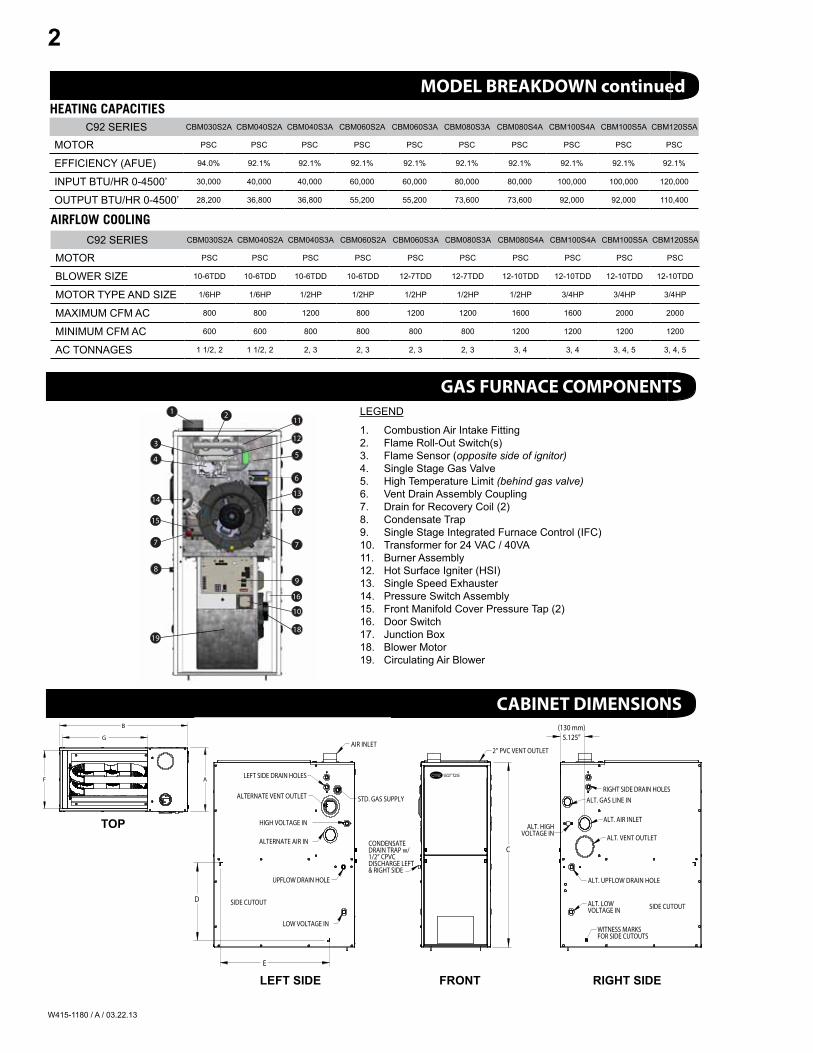
LEGEND
1. Combustion Air Intake Fitting2. Flame Roll-Out Switch(s)3. Flame Sensor (opposite side of ignitor)4. Single Stage Gas Valve5. High Temperature Limit (behind gas valve)6. Vent Drain Assembly Coupling7. Drain for Recovery Coil (2)8. Condensate Trap9. Single Stage Integrated Furnace Control (IFC)10. Transformer for 24 VAC / 40VA11. Burner Assembly12. Hot Surface Igniter (HSI)13. Single Speed Exhauster14. Pressure Switch Assembly15. Front Manifold Cover Pressure Tap (2)16. Door Switch17. Junction Box18. Blower Motor19. Circulating Air Blower
SIDE CUTOUT
LOW VOLTAGE IN
HIGH VOLTAGE IN
ALTERNATE VENT OUTLET
LEFT SIDE DRAIN HOLES
UPFLOW DRAIN HOLE
AIR INLET
ALTERNATE AIR IN
STD. GAS SUPPLY
D
E
& RIGHT SIDE
CONDENSATEDRAIN TRAP w/1/2” CPVCDISCHARGE LEFT
2” PVC VENT OUTLET
C
AF
G
B
ALT. VENT OUTLET
ALT. AIR INLET
FOR SIDE CUTOUTS
ALT. GAS LINE IN
VOLTAGE IN
ALT. UPFLOW DRAIN HOLE
ALT. LOW
VOLTAGE IN
WITNESS MARKS
ALT. HIGH
RIGHT SIDE DRAIN HOLES
SIDE CUTOUT
5.125”
C92 SERIES CBM030S2A CBM040S2A CBM040S3A CBM060S2A CBM060S3A CBM080S3A CBM080S4A CBM100S4A CBM100S5A CBM120S5A
MOTOR PSC PSC PSC PSC PSC PSC PSC PSC PSC PSC
EFFICIENCY (AFUE) 94.0% 92.1% 92.1% 92.1% 92.1% 92.1% 92.1% 92.1% 92.1% 92.1%
INPUT BTU/HR 0-4500’ 30,000 40,000 40,000 60,000 60,000 80,000 80,000 100,000 100,000 120,000
OUTPUT BTU/HR 0-4500’ 28,200 36,800 36,800 55,200 55,200 73,600 73,600 92,000 92,000 110,400
AIRFLOW COOLING
HEATING CAPACITIES
C92 SERIES CBM030S2A CBM040S2A CBM040S3A CBM060S2A CBM060S3A CBM080S3A CBM080S4A CBM100S4A CBM100S5A CBM120S5A
MOTOR PSC PSC PSC PSC PSC PSC PSC PSC PSC PSC
BLOWER SIZE 10-6TDD 10-6TDD 10-6TDD 10-6TDD 12-7TDD 12-7TDD 12-10TDD 12-10TDD 12-10TDD 12-10TDD
MOTOR TYPE AND SIZE 1/6HP 1/6HP 1/2HP 1/2HP 1/2HP 1/2HP 1/2HP 3/4HP 3/4HP 3/4HP
MAxIMUM CFM AC 800 800 1200 800 1200 1200 1600 1600 2000 2000
MINIMUM CFM AC 600 600 800 800 800 800 1200 1200 1200 1200
AC TONNAGES 1 1/2, 2 1 1/2, 2 2, 3 2, 3 2, 3 2, 3 3, 4 3, 4 3, 4, 5 3, 4, 5
TOP
lEfT SIdE fROnT RIghT SIdE
MODEL BREAKDOWN continued
GAS FURNACE COMPONENTS
CABINET DIMENSIONS
SIDE CUTOUT
LOW VOLTAGE IN
HIGH VOLTAGE IN
ALTERNATE VENT OUTLET
LEFT SIDE DRAIN HOLES
UPFLOW DRAIN HOLE
AIR INLET
ALTERNATE AIR IN
STD. GAS SUPPLY
D
E
& RIGHT SIDE
CONDENSATEDRAIN TRAP w/1/2” CPVCDISCHARGE LEFT
2” PVC VENT OUTLET
C
AF
G
B
ALT. VENT OUTLET
ALT. AIR INLET
FOR SIDE CUTOUTS
ALT. GAS LINE IN
VOLTAGE IN
ALT. UPFLOW DRAIN HOLE
ALT. LOW
VOLTAGE IN
WITNESS MARKS
ALT. HIGH
RIGHT SIDE DRAIN HOLES
SIDE CUTOUT
(130 mm)5.125”
W415-1180 / A / 03.22.13
3
PSC ESP 0.1” to 1.0” w.c.
InputMax A/C TAP
CFMTonnage NUMBER
CBM080S3A
N/A BLACK 1700
N/A BLUE 1400
3 TON YELLOW 1200
2 TON RED 800
CBM080S4A
5 TON BLACK 1900
4 TON BLUE 1600
N/A YELLOW 1400
3 TON RED 1200
CBM100S4A
5 TON BLACK 2000
5 TON BLUE 1900
4 TON YELLOW 1600
3 TON RED 1300
CBM100S5A
5 TON BLACK 2000
5 TON BLUE 1900
4 TON YELLOW 1600
3 TON RED 1300
CBM120S5A
5 TON BLACK 2000
5 TON BLUE 1900
4 TON YELLOW 1600
3 TON RED 1300
PSC ESP 0.1” to 1.0” w.c.
InputMAx A/C TAP
CFMTonnage COLOUR
CBM030S2A
2 TON BLACK 800
2 TON BLUE 700
1 1/2 TON YELLOW 600
1 1/2 TON RED 500
CBM040S2A
2 TON BLACK 800
2 TON BLUE 700
1 1/2 TON YELLOW 600
1 1/2 TON RED 500
CBM040S3A
N/A BLACK 1500
N/A BLUE 1400
3 TON YELLOW 1200
2 TON RED 800
CBM060S2A
N/A BLACK 1500
N/A BLUE 1400
3 TON YELLOW 1200
2 TON RED 800
CBM060S3A
N/A BLACK 1700
N/A BLUE 1400
3 TON YELLOW 1200
2 TON RED 800
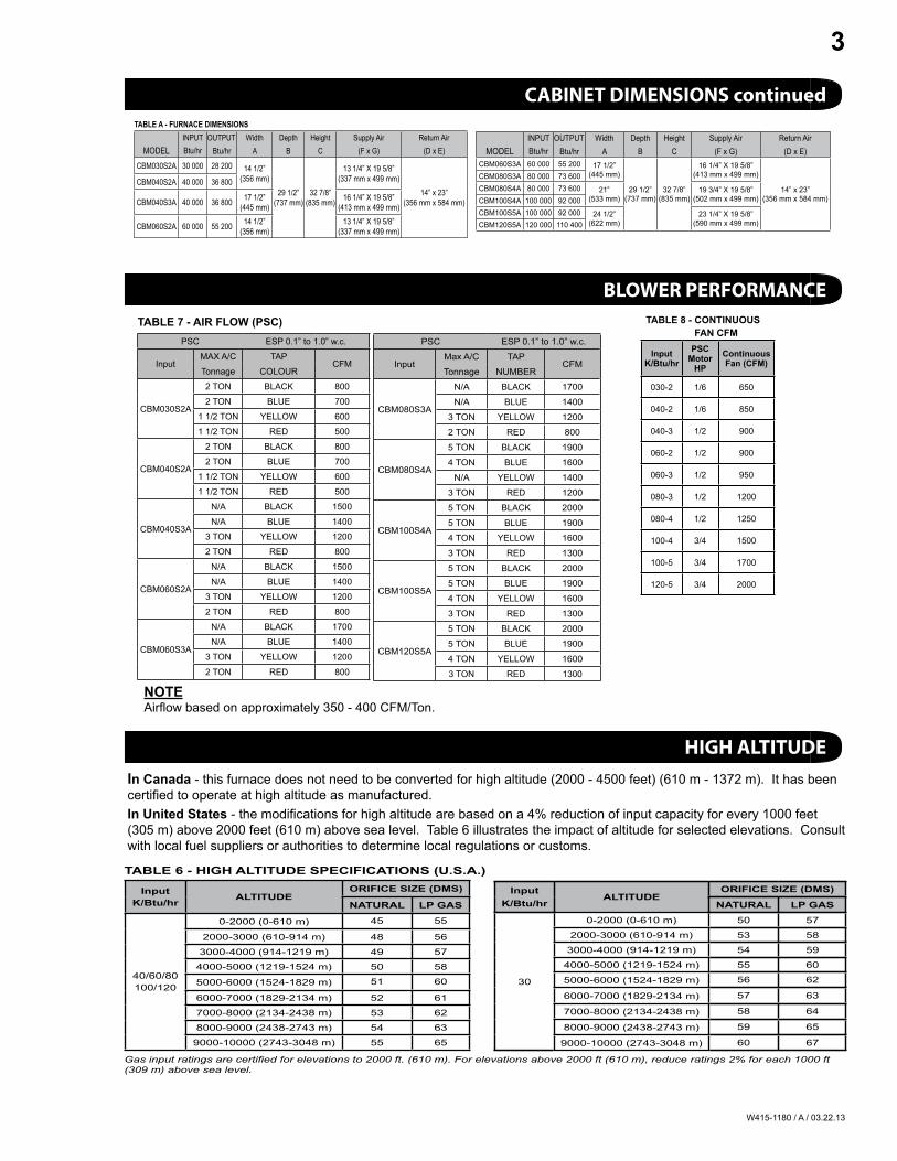
nOTEAirfl ow based on approximately 350 - 400 CFM/Ton.
TABlE 7 - AIR flOW (PSC) TABlE 8 - COnTInUOUS fAn CfM
InputK/Btu/hr
PSCMotor
hPContinuousfan (CfM)
030-2 1/6 650
040-2 1/6 850
040-3 1/2 900
060-2 1/2 900
060-3 1/2 950
080-3 1/2 1200
080-4 1/2 1250
100-4 3/4 1500
100-5 3/4 1700
120-5 3/4 2000
InputK/Btu/hr AlTITUdE
ORIfICE SIZE (dMS)
nATURAl lP gAS
40/60/80100/120
0-2000 (0-610 m) 45 55
2000-3000 (610-914 m) 48 56
3000-4000 (914-1219 m) 49 57
4000-5000 (1219-1524 m) 50 58
5000-6000 (1524-1829 m) 51 60
6000-7000 (1829-2134 m) 52 61
7000-8000 (2134-2438 m) 53 62
8000-9000 (2438-2743 m) 54 63
9000-10000 (2743-3048 m) 55 65
Input K/Btu/hr
AlTITUdEORIfICE SIZE (dMS)
nATURAl lP gAS
30
0-2000 (0-610 m) 50 57
2000-3000 (610-914 m) 53 58
3000-4000 (914-1219 m) 54 59
4000-5000 (1219-1524 m) 55 60
5000-6000 (1524-1829 m) 56 62
6000-7000 (1829-2134 m) 57 63
7000-8000 (2134-2438 m) 58 64
8000-9000 (2438-2743 m) 59 65
9000-10000 (2743-3048 m) 60 67
TABlE 6 - hIgh AlTITUdE SPECIfICATIOnS (U.S.A.)
Gas input ratings are certifi ed for elevations to 2000 ft. (610 m). For elevations above 2000 ft (610 m), reduce ratings 2% for each 1000 ft (309 m) above sea level.
In Canada - this furnace does not need to be converted for high altitude (2000 - 4500 feet) (610 m - 1372 m). It has been certified to operate at high altitude as manufactured.In United States - the modifications for high altitude are based on a 4% reduction of input capacity for every 1000 feet (305 m) above 2000 feet (610 m) above sea level. Table 6 illustrates the impact of altitude for selected elevations. Consult with local fuel suppliers or authorities to determine local regulations or customs.
TABlE A - fURnACE dIMEnSIOnSINPUT OUTPUT Width Depth Height Supply Air Return Air
MODEL Btu/hr Btu/hr A B C (F x G) (D x E)
CBM030S2A 30 000 28 200 14 1/2”(356 mm)
29 1/2”(737 mm)
32 7/8”(835 mm)
13 1/4” x 19 5/8”(337 mm x 499 mm)
14” x 23”(356 mm x 584 mm)
CBM040S2A 40 000 36 800
CBM040S3A 40 000 36 800 17 1/2” (445 mm)
16 1/4” x 19 5/8”(413 mm x 499 mm)
CBM060S2A 60 000 55 200 14 1/2”(356 mm)
13 1/4” x 19 5/8”(337 mm x 499 mm)
CBM060S3A 60 000 55 200 17 1/2” (445 mm)
29 1/2”(737 mm)
32 7/8”(835 mm)
16 1/4” x 19 5/8”(413 mm x 499 mm)
14” x 23”(356 mm x 584 mm)
CBM080S3A 80 000 73 600CBM080S4A 80 000 73 600 21”
(533 mm)19 3/4” x 19 5/8”
(502 mm x 499 mm)CBM100S4A 100 000 92 000CBM100S5A 100 000 92 000 24 1/2”
(622 mm)23 1/4” x 19 5/8”
(590 mm x 499 mm)CBM120S5A 120 000 110 400
TABlEAU A - dIMEnSIOnS dE lA fOURnAISE
DÉBIT RENDEMENT Largeur Profondeur Hauteur Sortie d’air Retour d’air
MODÈLE Btu/hr Btu/hr A B C (F x G) (D x E)
CBM030S2A 30 000 28 200 14 1/2”(356 mm)
29 1/2”(737 mm)
32 7/8”(835 mm)
13 1/4” x 19 5/8”(337 mm x 499 mm)
14” x 23”(356 mm x 584 mm)
CBM040S2A 40 000 36 800
CBM040S3A 40 000 36 800 17 1/2” (445 mm)
16 1/4” x 19 5/8”(413 mm x 499 mm)
CBM060S2A 60 000 55 200 14 1/2”(356 mm)
13 1/4” x 19 5/8”(337 mm x 499 mm)
CBM060S3A 60 000 55 200 17 1/2” (445 mm)
29 1/2”(737 mm)
32 7/8”(835 mm)
16 1/4” x 19 5/8”(413 mm x 499 mm)
14” x 23”(356 mm x 584 mm)
CBM080S3A 80 000 73 600CBM080S4A 80 000 73 600 21”
(533 mm)19 3/4” x 19 5/8”
(502 mm x 499 mm)CBM100S4A 100 000 92 000CBM100S5A 100 000 92 000 24 1/2”
(622 mm)23 1/4” x 19 5/8”
(590 mm x 499 mm)CBM120S5A 120 000 110 400
CABINET DIMENSIONS continued
BLOWER PERFORMANCE
HIGH ALTITUDE
TABlE A - fURnACE dIMEnSIOnSINPUT OUTPUT Width Depth Height Supply Air Return Air
MODEL Btu/hr Btu/hr A B C (F x G) (D x E)
CBM030S2A 30 000 28 200 14 1/2”(356 mm)
29 1/2”(737 mm)
32 7/8”(835 mm)
13 1/4” x 19 5/8”(337 mm x 499 mm)
14” x 23”(356 mm x 584 mm)
CBM040S2A 40 000 36 800
CBM040S3A 40 000 36 800 17 1/2” (445 mm)
16 1/4” x 19 5/8”(413 mm x 499 mm)
CBM060S2A 60 000 55 200 14 1/2”(356 mm)
13 1/4” x 19 5/8”(337 mm x 499 mm)
CBM060S3A 60 000 55 200 17 1/2” (445 mm)
29 1/2”(737 mm)
32 7/8”(835 mm)
16 1/4” x 19 5/8”(413 mm x 499 mm)
14” x 23”(356 mm x 584 mm)
CBM080S3A 80 000 73 600CBM080S4A 80 000 73 600 21”
(533 mm)19 3/4” x 19 5/8”
(502 mm x 499 mm)CBM100S4A 100 000 92 000CBM100S5A 100 000 92 000 24 1/2”
(622 mm)23 1/4” x 19 5/8”
(590 mm x 499 mm)CBM120S5A 120 000 110 400
TABlEAU A - dIMEnSIOnS dE lA fOURnAISE
DÉBIT RENDEMENT Largeur Profondeur Hauteur Sortie d’air Retour d’air
MODÈLE Btu/hr Btu/hr A B C (F x G) (D x E)
CBM030S2A 30 000 28 200 14 1/2”(356 mm)
29 1/2”(737 mm)
32 7/8”(835 mm)
13 1/4” x 19 5/8”(337 mm x 499 mm)
14” x 23”(356 mm x 584 mm)
CBM040S2A 40 000 36 800
CBM040S3A 40 000 36 800 17 1/2” (445 mm)
16 1/4” x 19 5/8”(413 mm x 499 mm)
CBM060S2A 60 000 55 200 14 1/2”(356 mm)
13 1/4” x 19 5/8”(337 mm x 499 mm)
CBM060S3A 60 000 55 200 17 1/2” (445 mm)
29 1/2”(737 mm)
32 7/8”(835 mm)
16 1/4” x 19 5/8”(413 mm x 499 mm)
14” x 23”(356 mm x 584 mm)
CBM080S3A 80 000 73 600CBM080S4A 80 000 73 600 21”
(533 mm)19 3/4” x 19 5/8”
(502 mm x 499 mm)CBM100S4A 100 000 92 000CBM100S5A 100 000 92 000 24 1/2”
(622 mm)23 1/4” x 19 5/8”
(590 mm x 499 mm)CBM120S5A 120 000 110 400
W415-1180 / A / 03.22.13
4
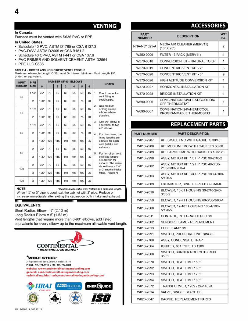
In Canada:Furnace must be vented with S636 PVC or PPEIn United States:• Schedule 40 PVC, ASTM D1785 or CSA B137.3• PVC-DWV, ASTM D2665 or CSA B181.2• Schedule 40 CPVC, ASTM F441 or CSA 137.6• PVC PRIMER AND SOLVENT CEMENT: ASTM D2564• PPE ULC S636TABlE 4 - dIRECT And nOn-dIRECT VEnT lEngThSMaximum Allowable Length Of Exhaust Or Intake. Minimum Vent Length 15ft.(4.6m) or equivalent.
InPUTK/Btu/hr
PIPE SIZE
nUMBER Of 90° ElBOWSnOTES
0 1 2 3 4 5 6
301 1/2 75* 70 65 60 55 50 45 1. Count concentric
vent fi tting as straight pipe.
2. Use medium or long sweep elbows where possible.
3. One 90° elbow is equivalent to two 45° elbows.
4. For direct vent, the listed lengths are allowed for each vent (intake and exhaust).
5. For non-direct vent, the listed lengths are allowed for exhaust. The intake should have a 1½” or 2” snorkel intake fi tting. (Figure 7)
2 100* 95 90 85 80 75 70
401 1/2 75* 70 65 60 55 50 45
2 100* 95 90 85 80 75 70
60
1 1/2 75* 70 65 60 55 50 45
2 100* 95 90 85 80 75 70
3 125* 120 115 110 105 100 95
802 75* 70 65 60 55 50 45
3 125* 120 115 110 105 100 95
1002 75* 70 65 60 55 50 45
3 125* 120 115 110 105 100 95
120 3 125* 120 115 110 105 100 95
nOTE * Maximum allowable vent (intake and exhaust) length.When 1½” or 3” pipe is used, exit the cabinet with 2” pipe. Reduce or increase immediately after exiting the cabinet on both intake and exhaust.
EQUIVAlEnTS:Short Radius Elbow = 7’ (2.13 m)Long Radius Elbow = 5’ (1.52 m)Vent lengths that require more than 6-90° elbows, add listed equivalents for every elbow up to the maximum allowable vent length.
PARTnUMBER dESCRIPTIOn WT/
lbs.
NNA-NC1625-A MEDIA AIR CLEANER (MERV11) (16” x 25”) 2
W250-0009 FILTER - 3 PACK (MERV11) 1
W370-0018 CONVERSION KIT - NATURAL TO LP 1
W370-0019 CONCENTRIC VENT KIT - 2” 5
W370-0020 CONCENTRIC VENT KIT - 3” 9
W370-0026 HIGH ALTITUDE CONVERSION KIT 1
W370-0027 HORIZONTAL INSTALLATION KIT 1
W370-0028 BRIDGE INSTALLATION KIT 1
W690-0006 COMBINATION 24V/HEAT/COOL ON/OFF THERMOSTAT 1
W690-0007 COMBINATION 24V/HEAT/COOL PROGRAMMABLE THERMOSTAT 1
PART nUMBER PART dESCRIPTIOn
W010-2987 KIT, SMALL FMC WITH GASKETS 30/40
W010-2988 KIT, MEDIUM FMC WITH GASKETS 60/80
W010-2989 KIT, LARGE FMC WITH GASKETS 100/120
W010-2990 ASSY, MOTOR KIT 1/6 HP PSC 30-2/40-2
W010-2602 ASSY, MOTOR KIT 1/2 HP PSC 40-3/60-2/60-3/80-3/80-4
W010-2603 ASSY, MOTOR KIT 3/4 HP PSC 100-4/100-5/120-5
W010-2609 ExHAUSTER, SINGLE SPEED C-FRAME
W010-2610 BLOWER, 10-6T HOUSING 30-2/40-2/40-3/60-2
W010-2559 BLOWER, 12-7T HOUSING 60-3/80-3/80-4
W010-2560 BLOWER, 12-10T HOUSING 100-4/100-5/120-5
W010-2611 CONTROL, INTEGRATED PSC SS
W010-2562 SENSOR, FLAME - REPLACEMENT
W010-2613 FUSE, 3 AMP SS
W010-2991 SWITCH, PRESSURE UNIT SINGLE
W010-2768 ASSY, CONDENSATE TRAP
W010-2564 IGNITER, 601 TYPE TB 120V
W010-2568 SWITCH, BURNER ROLLOUTS REPL 350°F
W010-2570 SWITCH, HEAT LIMIT 150°F
W010-2992 SWITCH, HEAT LIMIT 160°F
W010-2993 SWITCH, HEAT LIMIT 170°F
W010-2994 SWITCH, HEAT LIMIT 180°F
W010-2572 TRANSFORMER, 120V / 24V 40VA
W010-2614 VALVE, SINGLE STAGE SS
W020-0647 BAGGIE, REPLACEMENT PARTS
24 Napoleon Road, Barrie, Ontario, Canada L4M 4Y8
PHONE: 705-721-1212 • FAX: 705-722-6031website: www.continentalheatingandcooling.comgeneral: [email protected] inquiries: [email protected]
VENTING ACCESSORIES
REPLACEMENT PARTS
W415-1180 / A / 03.22.13
4
Au Canada :• La fournaise doit être ventilée avec un conduit PVC ou PPE S636 Aux États-Unis :• Série 40 PVC, ASTM D1785 ou CSA B137.3• PVC-DWV, ASTM D2665 ou CSA B181.2• Série 40 CPVC, ASTM D1785 ou CSA B137.3• APPRÊT ET COLLE À SOLVANT POUR PVC : ASTM D2564• PPE ULC S636
ÉQUIVALENCES :Coude court de rayon = 7’ (pieds) (2.13 m) Long rayon coude = 5’ (pieds) (1.52 m)Les longueurs d’évent qui nécessitent plus de 6-90 ° revêtues, ajouter cotées équivalents pour chaque coude jusqu’à la longueur maximale autorisée.
ACCESSOIRES
PIÈCES DE RECHANGE
PARTNUMBERDESCRIPTIONWT/
lbs.
NNA-NC1625-ABOÎTIER ET FILTRE (MERV11) (16” X 25”)2
W250-0009FILTRE DE RECHANGE - PAQUET DE 3 (MERV11)1
W370-0018KIT DE CONVERSION - NATUREL DE LP1
W370-0019ENSEMBLE D’ÉVENTS CONCENTRIQUES - 2” 5
W370-0020ENSEMBLE D’ÉVENTS CONCENTRIQUES - 3” 9
W370-0026ENSEMBLE DE CONVERSION HAUTE ALTITUDE 1
W370-0027KIT DE MONTAGE HORIZONTAL1
W370-0028ENSEMBLE DE JONCTION1
W690-0006THERMOSTAT MARCHE/ARRÊT COMBINÉ 24 V POUR LE CHAUFFAGE ET LA CLIMATISATION
1
W690-0007THERMOSTAT PROGRAMMABLE COMBINÉ 24 V POUR LE CHAUFFAGE ET LA CLIMATISATION
1
24 Napoleon Road, Barrie, Ontario, Canada L4M 4Y8
PHONE: 705-721-1212 • FAX: 705-722-6031site Web : www.chauff ageetclimatisationcontinental.com
questions générales : [email protected]
questions techniques : [email protected]
ÉVACUATION
NUMÉRO DE PIÈCEDESCRIPTION
W010-2987 PETIT COUVERCLE DU COLECTEUR AVANT AVEC JOINTS D’ÉTANCHÉITÉ 30/40
W010-2988MÉDIUM COUVERCLE DU COLECTEUR AVANT AVEC JOINTS D’ÉTANCHÉITÉ 60/80
W010-2989 GRAND COUVERCLE DU COLECTEUR AVANT AVEC JOINTS D’ÉTANCHÉITÉ 100/120
W010-2990ASSEMBLAGE DE MOTEUR 1/6 HP PSC 30-2/40-2
W010-2602ASSEMBLAGE DE MOTEUR 1/2 HP PSC 40-3/60-2/60-3/80-3/80-4
W010-2603ASSEMBLAGE DE MOTEUR 3/4 HP PSC 100-4/100-5/120-5
W010-2609VENTILATEUR D’ÉVACUATION À UNE VITESSE
W010-2610BOÎTIER DE SOUFFLERIE 10-6T 45/60 SS
W010-2559BOÎTIER DE SOUFFLERIE 12-7T 80
W010-2560BOÎTIER DE SOUFFLERIE 12-10T 100/120
W010-2611COMMANDE INTÉGRÉE PSC SS
W010-2562CAPTEUR DE FLAMME – RECHANGE
W010-2613FUSIBLE 3 A SS
W010-2991INTERRUPTEUR, UNITÉ DE PRESSION
W010-2768ASSEMBLAGE, PURGEUR DE CONDENSAT
W010-2564ALLUMEUR 601 TYPE TB 120 V
W010-2568INTERRUPTEUR DU BRÛLEUR, RECHANGE, 350 °F
W010-2570LIMITEUR DE CHALEUR DE 150 °F
W010-2992LIMITEUR DE CHALEUR DE 160 °F
W010-2993LIMITEUR DE CHALEUR DE 170 °F
W010-2994LIMITEUR DE CHALEUR DE 180 °F
W010-2572TRANSFORMATEUR, 120 V / 24 V / 40 VA
W010-2614SOUPAGE, UNE ÉTAPE SS
W020-0647SAC, PIÈCES DE RECHANGE
TABLEAU 4 - LONGUEURS DES CONDUITS D’ÉVENT DIRECT ET INDIRECTLongueur maximale permise des conduits d’évacuation et d’alimentation en air. Lon-gueur minimale du conduit : 15 pieds (4.6 m) ou l’équivalent.
DÉBIT kBTU/h
DI-MENS. CON-DUIT
NOMBRE DE COUDES DE 90°
NOTES0123456
301 1/275*7065605550451. Considérez un
raccord de conduit concentrique comme un conduit droit.
2. Utilisez des coudes à moyen et grand rayons, lorsque possible.
3. Un coude de 90° équivaut à deux coudes de 45°.
4. Dans le cas d’un système d”évent direct, les longueurs indiquées sont permises pour chacun des conduits (alimentation en air et évacuation).
5. Pour le système d’évent indirect, les longueurs indiquées ne s’appliquent qu’à l’évacuation. La prise d’air doit être munie d’un raccord à col recourbé de 1 1/2 à 2’’. (Figure 7)
2100*959085807570
401 1/275*706560555045
2100*959085807570
60
1 1/275*706560555045
2100*959085807570
3125*12011511010510095
80275*706560555045
3125*12011511010510095
100275*706560555045
3125*12011511010510095
1203125*12011511010510095
NOTE * Apport admissible maximal et longueurs d’évent d’échappement.À la sortie du caisson, le conduit doit avoir 2’’, même si vous utilisez des conduits de 1 1/2 ou 3’’. Réduisez ou augmentez la taille du conduit d’alimentation en air et du conduit d’évacuation dès la sortie du caisson.
W415-1180 / A / 03.22.13
3
PERFORMANCE DE LA SOUFFLERIE
PSCESP 0.1” à 1,0” CE
DébitTONNAGECOULEUR DU
PI3/MA/CROBINET
CBM080S3A
N/A NOIR1700
N/ABLEU1400
3 TONJAUNE1200
2 TONROUGE800
CBM080S4A
5 TONNOIR1900
4 TONBLEU1600
N/AJAUNE1400
3 TONROUGE1200
CBM100S4A
5 TONNOIR2000
5 TONBLEU1900
4 TONJAUNE1600
3 TONROUGE1300
CBM100S5A
5 TONNOIR2000
5 TONBLEU1900
4 TONJAUNE1600
3 TONROUGE1300
CBM120S5A
5 TONNOIR2000
5 TONBLEU1900
4 TONJAUNE1600
3 TONROUGE1300
PSCESP 0,1” à 1,0” CE
DébitTONNAGECOULEUR DU
PI3/MA/CROBINET
CBM030S2A
2 TONNOIR800
2 TONBLEU700
1 1/2 TONJAUNE600
1 1/2 TONROUGE500
CBM040S2A
2 TONNOIR800
2 TONBLEU700
1 1/2 TONJAUNE600
1 1/2 TONROUGE500
CBM040S3A
N/ANOIR1500
N/ABLEU1400
3 TONJAUNE1200
2 TONROUGE800
CBM060S2A
N/ANOIR1500
N/ABLEU1400
3 TONJAUNE1200
2 TONROUGE800
CBM060S3A
N/ANOIR1700
N/ABLEU1400
3 TONJAUNE1200
2 TONROUGE800
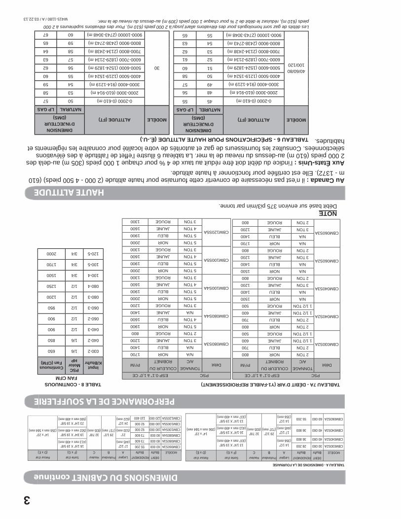
NOTEDébit basé sur environ 375 pi3/min par tonne.
TABLEAU 7A - DÉBIT D’AIR (Y1-FAIBLE REFROIDISSEMENT) TABLE 8 - CONTINUOUS FAN CFM
InputK/Btu/hr
PSCMotor
HPContinuousFan (CFM)
030-21/6650
040-21/6850
040-31/2900
060-21/2900
060-31/2950
080-31/21200
080-41/21250
100-43/41500
100-53/41700
120-53/42000
HAUTE ALTITUDE
MODÈLEALTITUDE (FT)
DIMENSION D’INJECTEUR
(DMS)
NATURELLP GAS
40/60/80100/120
0-2000 (0-610 m)4555
2000-3000 (610-914 m)4856
3000-4000 (914-1219 m)4957
4000-5000 (1219-1524 m)5058
5000-6000 (1524-1829 m)5160
6000-7000 (1829-2134 m)5261
7000-8000 (2134-2438 m)5362
8000-9000 (2438-2743 m)5463
9000-10000 (2743-3048 m)5565
MODÈLEALTITUDE (FT)
DIMENSION D’INJECTEUR
(DMS)
NATURALLP GAS
30
0-2000 (0-610 m)5057
2000-3000 (610-914 m)5358
3000-4000 (914-1219 m)5459
4000-5000 (1219-1524 m)5560
5000-6000 (1524-1829 m)5662
6000-7000 (1829-2134 m)5763
7000-8000 (2134-2438 m)5864
8000-9000 (2438-2743 m)5965
9000-10000 (2743-3048 m)6067
TABLEAU 6 - SPÉCIFICATIONS POUR HAUTE ALTITUDE (É.-U.)
Les débits de gaz sont homologués pour des élévations allant jusqu’à 2 000 pieds (610 m). Pour des élévations supérieures à 2 000 pieds (610 m), réduisez le débit de 2 % pour chaque 1 000 pieds (309 m) au-dessus du niveau de la mer.
Au Canada : il n’est pas nécessaire de convertir cette fournaise pour haute altitude (2 000 - 4 500 pieds) (610 m - 1372). Elle est certifi ée pour fonctionner à haute altitude.Aux États-Unis : l’indice du débit doit être réduit au taux de 4 % pour chaque 1 000 pieds (305 m) au-delà des 2 000 pieds (610 m) au-dessus du niveau de la mer. La tableau 6 illustre l’effet de l’altitude à des élévations sélectionnées. Consultez les fournisseurs de gaz et autorités de votre localité pour connaître les règlements et habitudes.
DIMENSIONS DU CABINET continue
TABLEAU A - DIMENSIONS DE LA FOURNAISE
DÉBITRENDEMENTLargeurProfondeurHauteurSortie d’airRetour d’air
MODÈLEBtu/hrBtu/hrABC(F x G)(D x E)
CBM030S2A30 00028 20014 1/2”(356 mm)
29 1/2”(737 mm)
32 7/8”(835 mm)
13 1/4” X 19 5/8”(337 mm x 499 mm)
14” x 23”(356 mm x 584 mm)
CBM040S2A40 00036 800
CBM040S3A40 00036 80017 1/2” (445 mm)
16 1/4” X 19 5/8”(413 mm x 499 mm)
CBM060S2A60 00055 20014 1/2”(356 mm)
13 1/4” X 19 5/8”(337 mm x 499 mm)
(356)(3399)
CBM060S3A60 00055 20017 1/2” (445 mm)
29 1/2”(737 mm)
32 7/8”(835 mm)
16 1/4” X 19 5/8”(413 mm x 499 mm)
14” x 23”(356 mm x 584 mm)
CBM080S3A80 00073 600CBM080S4A80 00073 60021”
(533 mm)19 3/4” X 19 5/8”
(502 mm x 499 mm) CBM100S4A100 00092 000CBM100S5A100 00092 00024 1/2”
(622 mm)23 1/4” X 19 5/8”
(590 mm x 499 mm) CBM120S5A120 000110 400
DÉBITRENDEMENTLargeurProfondeurHauteurSortie d’airRetour d’air
MODÈLEBtu/hrBtu/hrABC(F x G)(D x E)
W415-1180 / A / 03.22.13
2
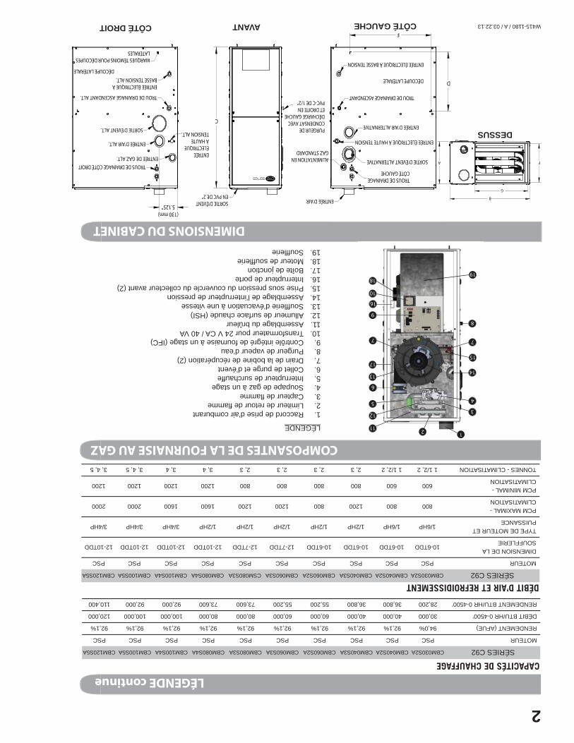
COMPOSANTES DE LA FOURNAISE AU GAZ
LÉGENDE
1. Raccord de prise d’air comburant2. Limiteur de retour de fl amme3. Capteur de fl amme4. Soupape de gaz à un stage5. Interrupteur de surchauffe6. Collet de purge et d’évent7. Drain de la bobine de récupération (2)8. Purgeur de vapeur d’eau9. Contrôle intégré de fournaise à un stage (IFC)10. Transformateur pour 24 V CA / 40 VA11. Assemblage du brûleur12. Allumeur de surface chaude (HSI)13. Souffl erie d’évacuation à une vitesse14. Assemblage de l’interrupteur de pression15. Prise sous pression du couvercle du collecteur avant (2)16. Interrupteur de porte 17. Boîte de jonction18. Moteur de souffl erie19. Souffl erie
DIMENSIONS DU CABINET
DÉBIT D’AIR ET REFROIDISSEMENT
CAPACITÉS DE CHAUFFAGESÉRIES C92CBM030S2ACBM040S2ACBM040S3ACBM060S2ACBM060S3ACBM080S3ACBM080S4ACBM100S4ACBM100S5ACBM120S5A
MOTEURPSCPSCPSCPSCPSCPSCPSCPSCPSCPSC
RENDEMENT (AFUE)94,0%92,1%92,1%92,1%92,1%92,1%92,1%92,1%92,1%92,1%
DÉBIT BTU/HR 0-4500’30,00040,00040,00060,00060,00080,00080,000100,000100,000120,000
RENDEMENT BTU/HR 0-4500’28,20036,80036,80055,20055,20073,60073,60092,00092,000110,400
SÉRIES C92CBM030S2ACBM040S2ACBM040S3ACBM060S2ACBM060S3ACSM080S3ACBM080S4ACBM100S4ACBM100S5ACBM120S5A
MOTEURPSCPSCPSCPSCPSCPSCPSCPSCPSCPSC
DIMENSION DE LA SOUFFLERIE
10-6TDD10-6TDD10-6TDD10-6TDD12-7TDD12-7TDD12-10TDD12-10TDD12-10TDD12-10TDD
TYPE DE MOTEUR ET PUISSANCE
1/6HP1/6HP1/2HP1/2HP1/2HP1/2HP1/2HP3/4HP3/4HP3/4HP
PCM MAXIMAL - CLIMATISATION
8008001200800120012001600160020002000
PCM MINIMAL - CLIMATISATION
6006008008008008001200120012001200
TONNES - CLIMATISATION1 1/2, 21 1/2, 22, 32, 32, 32, 33, 43, 43, 4, 53, 4, 5
1211
12
1918
17
16
15
1413
35 4
6
7
89
10
7
A F
G
B
DÉCOUPE LATÉRALE
ENTRÉE ÉLECTRIQUE À BASSE TENSION
ENTRÉE ÉLECTRIQUE À HAUTE TENSION
SORTIE D'ÉVENT ALTERNATIVE
TROUS DE DRAINAGE CÔTÉ GAUCHE
TROU DE DRAINAGE ASCENDANT
ENTRÉE D'AIR
ENTRÉE D'AIR ALTERNATIVE
ALIMENTATION EN GAZ STANDARD
D
E
PURGEUR DE CONDENSAT AVEC DÉCHARGE GAUCHE ET DROITE EN PVC-C DE 1/2"
SORTIE D'ÉVENT EN PVC DE 2"
CSORTIE D'ÉVENT ALT.
ENTRÉE D'AIR ALT.
MARQUES TÉMOINS POUR DÉCOUPES LATÉRALES
ENTRÉE DE GAZ ALT.
ENTRÉE ÉLECTRIQUE À BASSE TENSION ALT.
TROU DE DRAINAGE ASCENDANT ALT.
ENTRÉE ÉLECTRIQUE À HAUTE TENSION ALT.
TROUS DE DRAINAGE CÔTÉ DROIT
DÉCOUPE LATÉRALE
(130 mm)5.125”
DESSUS
CÔTÉ GAUCHEAVANTCÔTÉ DROIT
LÉGENDE continue
W415-1180 / A / 03.22.13
1
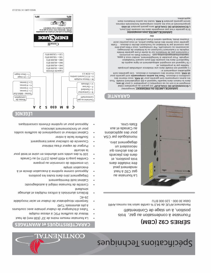
SÉRIES C92 (CBM)Fournaise à condensation au gaz, trois position, à un stage de Continental® Rendement AFUE de 94,0 % certifi é selon les normes AHRIDébit 30 000 - 120 000 BTU
La fournaise au gaz C92 à haut rendement peut être installée dans trois positions, et dans des placards et des alcôves qui nécessitent un dégagement zéro. Homologuée par CSA pour des applications au Canada et aux États-Unis.
GARANTIE LIMITÉE DU PRÉSIDENT (enregistrée)L’ÉCHANGEUR DE CHALEUR* est garanti au propriétaire initial enregistré et à son ou sa conjoint(e) (« propriétaire ») pour 20 ans, dans la maison dans laquelle l’appareil a été originalement installé. Tous les autres composants sont garantis pour 10 ANS, sous réserve des conditions ci-dessous. Tous les autres composants sont garantis pour 10 ANS, sous réserve des conditions ci-dessous. Ces garanties sont applicables uniquement si :• L’appareil est installé dans une résidence unifamiliale principale
habitée par le propriétaire, et• Si l’appareil est enregistré adéquatement en ligne auprès de
Napoléon® dans les soixante (60) jours suivant l’installation originale. Pour procéder à l’enregistrement, rendez-vous à www.napoleonheatingandcooling.com. Certains États ou provinces n’autorisent pas de limitations sur la durée d’une garantie limitée implicite ni n’autorisent l’exclusion ou la limitation de dommages accessoires ou consécutifs. Par conséquent, vous n’êtes peut-être pas concerné par la limitation ou l’exclusion décrite ci-dessus. Cette garantie vous donne des droits légaux précis, et vous pourriez avoir d’autres droits, lesquels varient d’une juridiction à l’autre.
OUGARANTIE LIMITÉE (non enregistrée)
Si la garantie n’est pas enregistrée dans les soixante (60) jours, L’ÉCHANGEUR DE CHALEUR sera garanti pendant 20 ANS (proportionnel) et tous les autres composants fonctionnels internes seront garantis pendant 5 ANS, toutes les autres limitations étant applicables.
GARANTIE LIMITÉE DU PRÉSIDENT(enregistrée)L’ÉCHANGEUR DE CHALEUR* est garanti au propriétaire initial enregistré et à son ou sa conjoint(e) (« propriétaire ») pour 20 ans,dans la maison dans laquelle l’appareil a été originalement installé. Tous les autres composants sont garantis pour 10 ANS, sous réserve des conditions ci-dessous. Tous les autres composants sont garantis pour 10 ANS, sous réserve des conditions ci-dessous. Ces garanties sontapplicables uniquement si :• L’appareil est installé dans une résidence unifamiliale principale
habitée par le propriétaire, et• Si l’appareil est enregistré adéquatement en ligne auprès de
Napoléon® dans les soixante (60) jours suivant l’installation originale. Pour procéder à l’enregistrement, rendez-vous à www.napoleonheatingandcooling.com pgg. Certains États ou provinces n’autorisent pas de limitations sur la durée d’une garantie limitéeimplicite ni n’autorisent l’exclusion ou la limitation de dommages accessoires ou consécutifs. Par conséquent, vous n’êtes peut-êtrepas concerné par la limitation ou l’exclusion décrite ci-dessus. Cette garantie vous donne des droits légaux précis, et vous pourriez avoir d’autres droits, lesquels varient d’une juridiction à l’autre.
GARANTIE LIMITÉE (non enregistrée) (g)Si la garantie n’est pas enregistrée dans les soixante (60) jours, L’ÉCHANGEUR DE CHALEUR sera garanti pendant 20 ANS(proportionnel) et tous les autres composants fonctionnels internesseront garantis pendant5 ANS, toutes les autres limitations étantapplicables.
• La fournaise mesure moins de 33” (838 mm) de haut• Moteur de souffl erie PSC à vitesse multiple • Tubes d’échangeur de chaleur primaire avec courbures
à plis aluminisés T140• Serpentin récupérateur de chaleur en acier inoxydable
29-4C• Brûleurs aluminisés à orifi ces multiples et allumage
simultané• Contrôle de fournaise intégré à autodiagnostic• Cabinet isolé thermiquement • Dégagement zéro dans toutes les positions • Approuvé comme système à évacuation directe et à
évacuation simple• Un ensemble de conversion au propane• Certifi ée jusqu’à 4500 pieds (1372 m) au Canada• 100 % des unités sont allumées en usine et testé pour
la sécurité• Purgeur de vapeur d’eau intérieur • Couvercle de collecteur avant transparent• Souffl erie facile à retirer• Cabinet inférieur et compartiment de souffl erie scellés
pour un fonctionnement silencieux• Approuvé pour un système d’évents concentriques
CBM030S2A
Fournaise au gaz Continental
B = ContracteurS = StandardP = De luxeU = Ultimate
M = Vitesse multipleX = X13 Courant continuV = ECM 2.3
Niveau de conception
Tonnes - débit d’air2 = 2 tonnes3 = 3 tonnes4 = 4 tonnes5 = 5 tonnes
S = Un stageT = Deux stages
Capacité d’entrée030 = 30,000 BTU040 = 40,000 BTU060 = 60,000 BTU080 = 80,000 BTU100 = 100,000 BTU120 = 120,000 BTU
GARANTIE
CARACTÉRISTIQUES et AVANTAGES
92,1 - 94,0CE MODÈLE
Spécifi cations Techniques
LÉGENDE