![PLFY-P·VBM-EVAM][VEM]/2016-2014/PLFY-P...• Use power line cables of sufficient current carrying capacity and rating. • Use only a circuit breaker and fuse of the specified capacity.](https://static.fdocuments.net/doc/165x107/5e66b6828b4c6c2a76686096/plfy-pvbm-e-vamvem2016-2014plfy-p-a-use-power-line-cables-of-sufficient.jpg)
TECHNICAL & SERVICE MANUAL - MyLinkDrivemeus1.mylinkdrive.com/files/PLFY-NAMU-E.pdf · octave band...
36
SPLIT-TYPE, HEAT PUMP AIR CONDITIONERS TECHNICAL & SERVICE MANUAL [Models] PLFY-P12NAMU-E PLFY-P15NAMU-E PLFY-P18NAMU-E PLFY-P24NAMU-E PLFY-P30NAMU-E PLFY-P36NAMU-E No. OC340 REVISED EDITION-A INDOOR UNIT CONTENTS 1. FEATURES····························································· 2 2. PART NAMES AND FUNCTIONS ························· 3 3. SPECIFICATIONS ·················································· 5 4. 4-WAY AIR FLOW SYSTEM ·································· 8 5. OUTLINES AND DIMENSIONS ····························· 11 6. WIRING DIAGRAM ················································ 12 7. REFRIGERANT SYSTEM DIAGRAM······················· 13 8. MICROPROCESSOR CONTROL ·························· 14 9. TROUBLE SHOOTING ·········································· 21 10. DISASSEMBLY PROCEDURE ······························ 26 11. PARTS LIST ··························································· 29 12. RoHS PARTS LIST ················································ 32 13. OPTIONAL PARTS················································· 35 August 2006 R410A / R22 NOTE: • This manual describes only service data of the indoor units. • RoHS compliant products have <G> mark on the spec name plate. • For servicing of RoHS compli- ant products, refer to the RoHS PARTS LIST. Revision: • RoHS PARTS LIST is added. • Some descriptions have been modified. • Please void OC340.
Transcript of TECHNICAL & SERVICE MANUAL - MyLinkDrivemeus1.mylinkdrive.com/files/PLFY-NAMU-E.pdf · octave band...
SPLIT-TYPE, HEAT PUMP AIR CONDITIONERS
TECHNICAL & SERVICE MANUAL
[Models] PLFY-P12NAMU-EPLFY-P15NAMU-EPLFY-P18NAMU-EPLFY-P24NAMU-EPLFY-P30NAMU-EPLFY-P36NAMU-E
No. OC340REVISED EDITION-A
INDOOR UNIT
CONTENTS
1. FEATURES····························································· 22. PART NAMES AND FUNCTIONS ························· 33. SPECIFICATIONS ·················································· 54. 4-WAY AIR FLOW SYSTEM ·································· 85. OUTLINES AND DIMENSIONS ····························· 116. WIRING DIAGRAM ················································ 127. REFRIGERANT SYSTEM DIAGRAM ······················· 138. MICROPROCESSOR CONTROL ·························· 149. TROUBLE SHOOTING ·········································· 21
10. DISASSEMBLY PROCEDURE ······························ 2611. PARTS LIST ··························································· 2912. RoHS PARTS LIST ················································ 3213. OPTIONAL PARTS················································· 35
August 2006
R410A / R22
NOTE:• This manual describes only
service data of the indoorunits.
• RoHS compliant products have<G> mark on the spec nameplate.
• For servicing of RoHS compli-ant products, refer to the RoHSPARTS LIST.
Revision:• RoHS PARTS LIST is added.• Some descriptions have been
modified.
• Please void OC340.
OC340A--1.qxp 06.7.25 0:39 PM Page 1
2
1 FEATURES
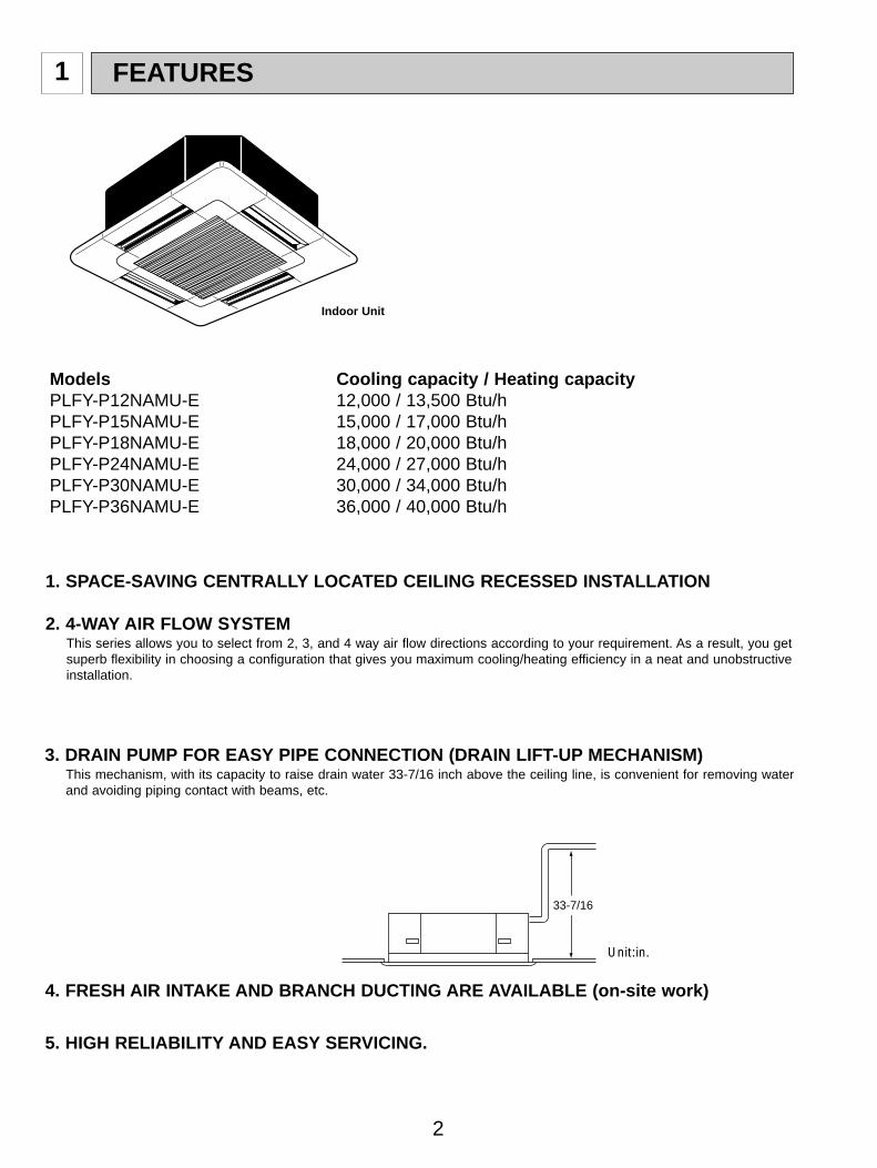
1. SPACE-SAVING CENTRALLY LOCATED CEILING RECESSED INSTALLATION
2. 4-WAY AIR FLOW SYSTEMThis series allows you to select from 2, 3, and 4 way air flow directions according to your requirement. As a result, you getsuperb flexibility in choosing a configuration that gives you maximum cooling/heating efficiency in a neat and unobstructiveinstallation.
Models Cooling capacity / Heating capacityPLFY-P12NAMU-E 12,000 / 13,500 Btu/hPLFY-P15NAMU-E 15,000 / 17,000 Btu/hPLFY-P18NAMU-E 18,000 / 20,000 Btu/hPLFY-P24NAMU-E 24,000 / 27,000 Btu/hPLFY-P30NAMU-E 30,000 / 34,000 Btu/hPLFY-P36NAMU-E 36,000 / 40,000 Btu/h
Indoor Unit
5. HIGH RELIABILITY AND EASY SERVICING.
3. DRAIN PUMP FOR EASY PIPE CONNECTION (DRAIN LIFT-UP MECHANISM)This mechanism, with its capacity to raise drain water 33-7/16 inch above the ceiling line, is convenient for removing waterand avoiding piping contact with beams, etc.
4. FRESH AIR INTAKE AND BRANCH DUCTING ARE AVAILABLE (on-site work)
33-7/16
Unit:in.
OC340A--1.qxp 06.7.25 0:39 PM Page 2

3
2 PART NAMES AND FUNCTIONS
Indoor (Main) Unit
Auto Air Swing VaneDisperses airflow up anddown and adjusts the angleof airflow direction.
Grille
FilterRemoves dust and pollutantsfrom return air
Horizontal Air OutletSets airflow horizontal automaticallyduring cooling or dehumidifying.
Air IntakeReturns air from room.
PAR-21MAA
ON/OFF
FILTER
CHECK
OPERATION CLEAR
TEST
TEMP.
MENU
BACK DAYMONITOR/SET
CLOCK
ON/OFF
Set Temperature buttons
Down
Up
Timer Menu button(Monitor/Set button)
Mode button (Return button)
Set Time buttons
Back
Ahead
Timer On/Off button(Set Day button)
Opening thedoor.
ON/OFF button
Fan Speed button
Filter button(<Enter> button)
Test Run button
Check button (Clear button)
Airflow Up/Down button
Louver button( Operation button)
To preceding operationnumber.
Ventilation button( Operation button)
To next operation number.
Remote controller Once the controls are set, the same operation mode can be repeated by simply pressing the ON/OFF button.
Operation buttons
OC340A--1.qxp 06.7.25 0:39 PM Page 3

4
Caution Only the Power on indicator lights when the unit is stopped and power supplied to the unit. If you press a button for a feature that is not installed at the indoor unit, the remote controller will display the “Not Available”
message.If you are using the remote controller to drive multiple indoor units, this message will appear only if the feature is not pre-sent at every unit connected.
When power is turned ON for the first time, it is normal that “PLEASE WAIT” is displayed on the room temperature indica-tion (For max. 2minutes). Please wait until this “PLEASE WAIT” indication disappear then start the operation.
Display
For purposes of this explanation,all parts of the display are shownas lit. During actual operation, onlythe relevant items will be lit.
˚F˚C
˚F˚C
ERROR CODEAFTER
TIMERTIME SUN MON TUE WED THU FRI SAT
ON
OFF
Hr
AFTER
FILTERFUNCTION
ONLY1Hr.
WEEKLYSIMPLE
AUTO OFF
Identifies the current operationShows the operating mode, etc.* Multilanguage display is sup-
ported.
“Centrally Controlled” indicatorIndicates that operation of the re-mote controller has been prohib-ited by a master controller.
“Timer Is Off” indicatorIndicates that the timer is off.
Temperature SettingShows the target temperature.
Day-of-WeekShows the current day of the week.
Time/Timer DisplayShows the current time, unless the simple or Auto Offtimer is set.If the simple or Auto Off timer is set, shows the timeremaining.
“Sensor” indicationDisplayed when the remote controller sensor is used.
“Locked” indicatorIndicates that remote controller but-tons have been locked.
“Clean The Filter” indicatorComes on when it is time to clean thefilter.
Timer indicatorsThe indicator comes on if the corre-sponding timer is set.
Up/Down Air Direction indica-torThe indicator shows the direc-tion of the outcoming airflow.
“One Hour Only” indicatorDisplayed if the airflow is set toLow and downward during COOLor DRY mode. (Operation variesaccording to model.)The indicator goes off after onehour, at which time the airflow di-rection also changes.
Room Temperature displayShows the room temperature.
Louver displayIndicates the action of the swinglouver. Does not appear if thelouver is stationary.
(Power On indicator)Indicates that the power is on.
Fan Speed indicatorShows the selected fan speed.
Ventilation indicatorAppears when the unit is running inVentilation mode.
OC340A--1.qxp 06.7.25 0:39 PM Page 4

5
3 SPECIFICATIONS
3-1. SPECIFICATIONS
Note 1. Rating conditionsCooling : Indoor : D.B. 80_F W.B. 67_F
outdoor : D.B. 95_F W.B. 75_FHeating : Indoor : D.B. 70_F
outdoor : D.B. 47_F W.B. 43_FNote 2. The number indicated in < > is just for the grille.
W 3. Air flow and the noise level are indicated as Low - Medium2 - Medium1 - High.
Item
Btu/h
Btu/h
kW
kW
A
A
—
in
in
in
—
—
CFM
CFM
Pa
kW
—
—
in
in
in
dB
lb
Cooling capacity
Power
Heat exchanger
Insulator
Air filter
Fan No
Pipedimensions
Unit drain pipe size
Noise level W3
Product weight
Exterior(munsell symbol)
Fan motoroutput
Externalstatic pressure
Liquidside
Gasside
Heating capacity
Fan
Dimensions
Height
Width
Depth
Elec
tric
char
acte
ristic
InputCooling
Heating
Cooling
HeatingCurrent
PLFY-P12NAMU-E PLFY-P18NAMU-E PLFY-P24NAMU-E PLFY-P30NAMU-E PLFY-P36NAMU-E
12,000
13,500
0.14
0.14
0.68
0.68
390-420-460-490
350-380-410-440
24-27-28-30
18,000
20,000
0.14
0.14
0.68
0.68
490-530-570-640
470-500-530-600
27-28-31-33
PLFY-P15NAMU-E
15,000
17,000
0.14
0.14
0.68
0.68
420-460-490-570
380-410-470-530
27-28-30-32
30,000
34,000
0.27
0.27
1.30
1.30
710-810-920-990
670-770-870-930
3/8"
34-36-40-41
36,000
40,000
0.27
0.27
1.30
1.30
780-880-990-1060
730-830-930-1000
5/8" / 3/4"(Compatible)
37-40-43-44
24,000
27,000
0.14
0.14
0.68
0.68
530-570-640-710
500-530-600-670
PVC with O.D.1-1/4"
28-30-33-34
Single phase 208/230V 60HzV·Hz
11-3/4<1-3/16>
0.110
5/8"
53<11> 66<11>
Air flow
W3
DRY
WET
Unit : Galvanized sheets with gray heat insulation Grills : ABS resin Munsell<0.70Y 8.59/0.97>
33-1/16<37-3/8>
33-1/16<37-3/8>
Cross fin
Turbo fan 1
0
Polyethylene sheet
PP honey comb fabric
10-3/16<1-3/16>
0.070
1/2"
1/4"
49<11>
1/2" / 5/8"(Compatible)
1/4" / 3/8"(Compatible)
OC340A--1.qxp 06.7.25 0:39 PM Page 5

6
3-2. NOISE CRITERION CURVES
90
80
70
60
50
40
30
20
1063 125 250 500 1000 2000 4000 8000
APPROXIMATETHRESHOLD OFHEARING FORCONTINUOUSNOISE
NC-60
NC-50
NC-40
NC-30
NC-20
NC-70
OC
TA
VE
BA
ND
SO
UN
D P
RE
SS
UR
E L
EV
EL
, dB
re
0.00
02 M
ICR
O B
AR
BAND CENTER FREQUENCIES, Hz
PLFY-P12NAMU-EHigh
Medium1Medium2
Low
NOTCH30282724
SPL(dB) LINE
90
80
70
60
50
40
30
20
1063 125 250 500 1000 2000 4000 8000
APPROXIMATETHRESHOLD OFHEARING FORCONTINUOUSNOISE
NC-60
NC-50
NC-40
NC-30
NC-20
NC-70
OC
TA
VE
BA
ND
SO
UN
D P
RE
SS
UR
E L
EV
EL
, dB
re
0.00
02 M
ICR
O B
AR
BAND CENTER FREQUENCIES, Hz
PLFY-P18NAMU-EHigh
Medium1Medium2
Low
NOTCH33312827
SPL(dB) LINE
90
80
70
60
50
40
30
20
1063 125 250 500 1000 2000 4000 8000
APPROXIMATETHRESHOLD OFHEARING FORCONTINUOUSNOISE
NC-60
NC-50
NC-40
NC-30
NC-20
NC-70
OC
TA
VE
BA
ND
SO
UN
D P
RE
SS
UR
E L
EV
EL
, dB
re
0.00
02 M
ICR
O B
AR
BAND CENTER FREQUENCIES, Hz
PLFY-P24NAMU-EHigh
Medium1Medium2
Low
NOTCH34333028
SPL(dB) LINE
90
80
70
60
50
40
30
20
1063 125 250 500 1000 2000 4000 8000
APPROXIMATETHRESHOLD OFHEARING FORCONTINUOUSNOISE
NC-60
NC-50
NC-40
NC-30
NC-20
NC-70
OC
TAV
E B
AN
D S
OU
ND
PR
ES
SU
RE
LE
VE
L, d
B r
e 0.
0002
MIC
RO
BA
R
BAND CENTER FREQUENCIES, Hz
PLFY-P15NAMU-EHigh
Medium1Medium2
Low
NOTCH32302827
SPL(dB) LINE
OC340A--1.qxp 06.7.25 0:39 PM Page 6
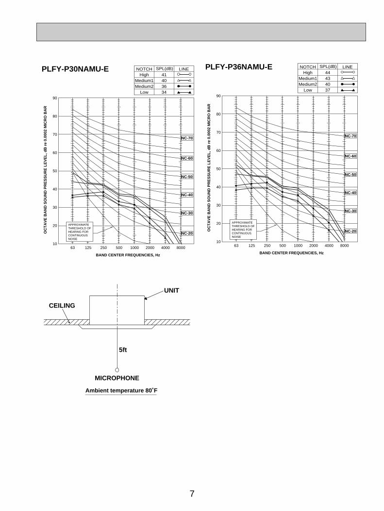
7
UNIT
5ft
MICROPHONE
CEILING
Ambient temperature 80˚F
90
80
70
60
50
40
30
20
1063 125 250 500 1000 2000 4000 8000
APPROXIMATETHRESHOLD OFHEARING FORCONTINUOUSNOISE
NC-60
NC-50
NC-40
NC-30
NC-20
NC-70
OC
TA
VE
BA
ND
SO
UN
D P
RE
SS
UR
E L
EV
EL
, dB
re
0.00
02 M
ICR
O B
AR
BAND CENTER FREQUENCIES, Hz
PLFY-P36NAMU-EHigh
Medium1Medium2
Low
NOTCH44434037
SPL(dB) LINE
90
80
70
60
50
40
30
20
1063 125 250 500 1000 2000 4000 8000
APPROXIMATETHRESHOLD OFHEARING FORCONTINUOUSNOISE
NC-60
NC-50
NC-40
NC-30
NC-20
NC-70
OC
TA
VE
BA
ND
SO
UN
D P
RE
SS
UR
E L
EV
EL
, dB
re
0.00
02 M
ICR
O B
AR
BAND CENTER FREQUENCIES, Hz
PLFY-P30NAMU-EHigh
Medium1Medium2
Low
NOTCH41403634
SPL(dB) LINE
OC340A--1.qxp 06.7.25 0:39 PM Page 7
8
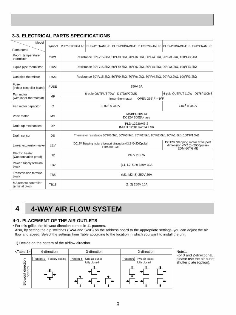
3-3. ELECTRICAL PARTS SPECIFICATIONS
Parts name
ModelSymbol
TH21
TH22
TH23
FUSE
MF
C
MV
DP
DS
LEV
H2
TB2
TB5
TB15
Resistance 30_F/15.8k", 50_F/9.6k", 70_F/6.0k", 80_F/4.8k", 90_F/3.9k", 100_F/3.2k"
Resistance 30_F/15.8k", 50_F/9.6k", 70_F/6.0k", 80_F/4.8k", 90_F/3.9k", 100_F/3.2k"
Resistance 30_F/15.8k", 50_F/9.6k", 70_F/6.0k", 80_F/4.8k", 90_F/3.9k", 100_F/3.2k"
250V 6A
240V 21.8W
(L1, L2, GR) 330V 30A
(M1, M2, S) 250V 20A
(1, 2) 250V 10A
Liquid pipe thermistor
Gas pipe thermistor
Fan motor capacitor
Vane motor
Drain-up mechanism
Drain sensor
Linear expansion valve
PLFY-P12NAMU-E PLFY-P18NAMU-EPLFY-P15NAMU-E PLFY-P24NAMU-E PLFY-P30NAMU-E PLFY-P36NAMU-E
Room temperaturethermistor
Fuse(Indoor controller board)
Fan motor(with inner-thermostat)
Electric heater(Condensation proof)
Power supply terminalblock
Transmission terminalblock
MA remote controller terminal block
6-pole OUTPUT 110W D176P110MS
Inner-thermostat OPEN 266°F i 9_F
6-pole OUTPUT 70W D17D6P70MS
MSBPC20M13DC12V 300"/phase
PLD-12220ME-2INPUT 12/10.8W 24R/Hr
Thermistor resistance 30_F/6.3k", 50_F/3.9k", 70_F/2.5k", 80_F/2.0k", 90_F/1.6k", 100_F/1.3k"
DC12V Stepping motor drive port dimension [3.2 (0~2000pulse)EDM-40YGME
DC12V Stepping motor drive portdimension [5.2 (0~2000pulse)
EDM-80YGME
3.0+ 440V 7.0+ 440V
4 4-WAY AIR FLOW SYSTEM4-1. PLACEMENT OF THE AIR OUTLETS• For this grille, the blowout direction comes in 11 patterns.
Also, by setting the dip switches (SWA and SWB) on the address board to the appropriate settings, you can adjust the airflow and speed. Select the settings from Table according to the location in which you want to install the unit.
1) Decide on the pattern of the airflow direction.
Blo
wou
t dire
ctio
npa
ttern
4-direction<Table 1> 3-direction 2-direction Note1.For 3 and 2-directional,please use the air outletshutter plate (option).
Pattern 1 Factory setting Pattern 4 One air outletfully closed
Pattern 6 Two air outletfully closed
OC340A--1.qxp 06.7.25 0:39 PM Page 8
9
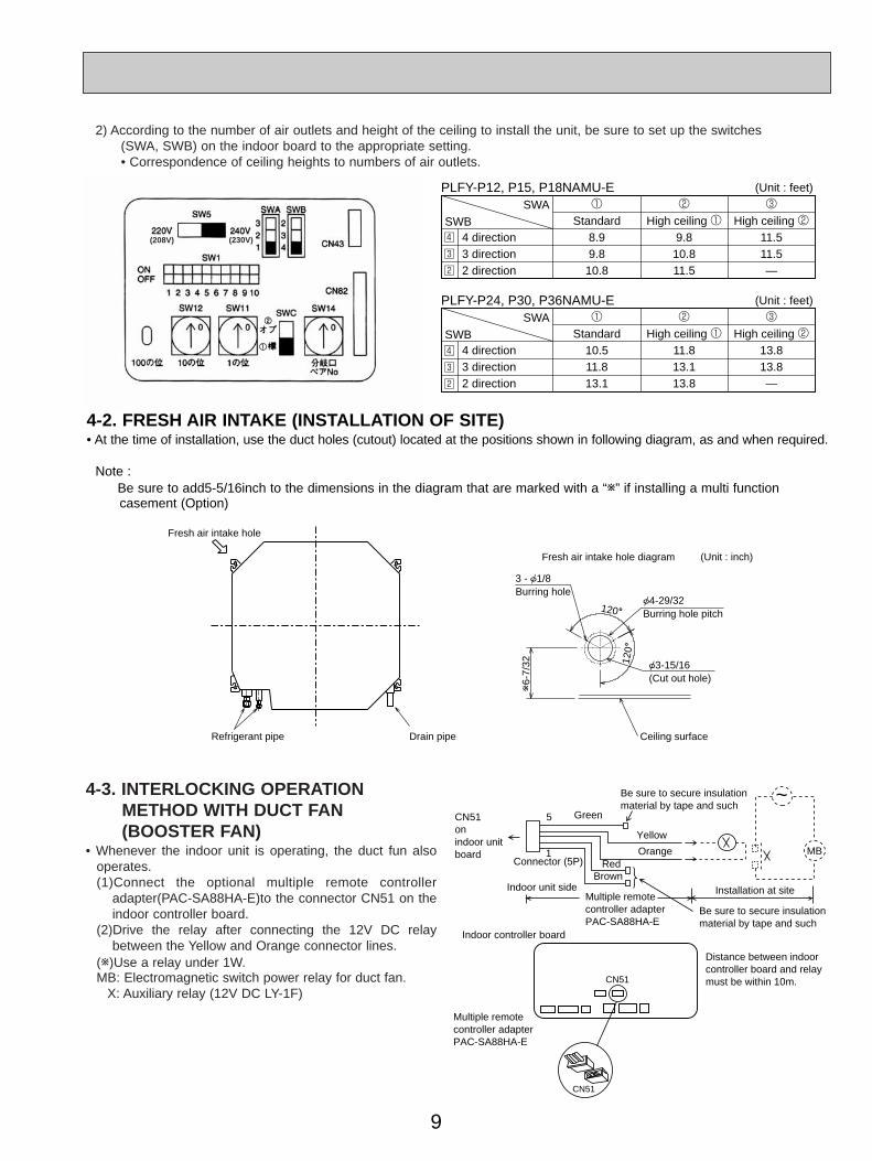
4-2. FRESH AIR INTAKE (INSTALLATION OF SITE)• At the time of installation, use the duct holes (cutout) located at the positions shown in following diagram, as and when required.
Note : Be sure to add5-5/16inch to the dimensions in the diagram that are marked with a “w” if installing a multi functioncasement (Option)
1
Standard8.99.810.8
2
High ceiling 19.810.811.5
(Unit : feet)
(Unit : feet)
3
High ceiling 211.511.5—
4 direction3 direction2 direction
SWASWB
PLFY-P12, P15, P18NAMU-E
PLFY-P24, P30, P36NAMU-E
4
3
2
1
Standard10.511.813.1
2
High ceiling 111.813.113.8
3
High ceiling 213.813.8—
4 direction3 direction2 direction
SWASWB4
3
2
2) According to the number of air outlets and height of the ceiling to install the unit, be sure to set up the switches (SWA, SWB) on the indoor board to the appropriate setting.• Correspondence of ceiling heights to numbers of air outlets.
Fresh air intake hole
Fresh air intake hole diagram (Unit : inch)
3 - 1/8Burring hole
4-29/32Burring hole pitch
3-15/16(Cut out hole)
Refrigerant pipe Drain pipe Ceiling surface
120_12
0_
w6-
7/32
4-3. INTERLOCKING OPERATIONMETHOD WITH DUCT FAN (BOOSTER FAN)
• Whenever the indoor unit is operating, the duct fun alsooperates.(1)Connect the optional multiple remote controller
adapter(PAC-SA88HA-E)to the connector CN51 on theindoor controller board.
(2)Drive the relay after connecting the 12V DC relaybetween the Yellow and Orange connector lines.
(w)Use a relay under 1W.MB: Electromagnetic switch power relay for duct fan.
X: Auxiliary relay (12V DC LY-1F)
CN51
Multiple remotecontroller adapterPAC-SA88HA-E
Indoor controller board
Distance between indoorcontroller board and relaymust be within 10m.
Be sure to secure insulationmaterial by tape and such
5 Green
Yellow
OrangeConnector (5P)
Indoor unit sideMultiple remotecontroller adapterPAC-SA88HA-E
Be sure to secure insulationmaterial by tape and such
Installation at site
CN51onindoor unitboard
RedBrown
1
~
CN51
MB
(208V) (230V)
11
22
OC340A--1.qxp 06.7.25 0:39 PM Page 9

10
Static pressure [in. W.G.]
Air flow [CFM]
2.0
50 100 150 200
0.2
0.4
0.6
0.8
0
2 intakes
1 intake
2 intakes
1 intake
Static pressure [in. W.G.]
Air flow [CFM]
2.0
50 100 150 200
0.2
0.4
0.6
0.8
0
Static pressure [in. W.G.]
Air flow [CFM]
2.0
50 100 150 200
0.2
0.4
0.6
0.8
0
Air flow[CFM]
2 intakes
1 intake
Static pressure [in. W.G.]
2.0
50 100 150 200 250 300
0.2
0.4
0.6
0.8
0 Air flow[CFM]
2 intakes
1 intake
Static pressure [in. W.G.]
2.050 100 150 200 250 300
0.2
0.4
0.6
0.8
0
Air flow [CFM]
Static pressure [in. W.G.]
2.0
50 100 150 200 250 300
0.2
0.4
0.6
0.8
0
ll PLFY-P12 /P15 /P18 /P24NAMU-EMultifunction casement + Standard filter
22 PLFY-P30 /P36NAMU-E
Multifunction casement + High efficiency filter
Taking air into the unit
Multifunction casement + Standard filter Multifunction casement + High efficiency filter
Taking air into the unit
4-4. FRESH AIR INTAKE AMOUNT & STATIC PRESSURE CHARACTERISTICS
Q
0
BA C
1 Curve in theleft graphs.
Duct characteristicsat site
Q
AE
C2
Q
Qa
AD
3
Q…Planned amount of fresh air intake
A…Static pressure loss of fresh airintake duct system with air flowamount Q
B…Forced static pressure at air condi-tioner inlet with air flow amount Q
C…Static pressure of booster fan withair flow amount Q
D…Static pressure loss increaseamount of fresh air intake duct sys-tem for air flow amount Q
E…Static pressure of indoor unit with airflow amount Q
Qa…Estimated amount of fresh airintake with out D <CFM>
<CFM>
<in.W.G.>
<in.W.G.>
<in.W.G.>
<in.W.G.>
How to read curves
<in.W.G.>
OC340A--1.qxp 06.7.25 0:39 PM Page 10

11
2
1
3-5/16(84)
3-5/32(80)
3-1/2(89)
11-1/16(281)
11-3/4(298) 5/8F / 3/4F
([15.88/[19.05)(Compatible)
5/8F
([15.88)
1/2F
([12.7)
3/8F
([9.52)
D
3(76)
PLFY-P36NAMU-E
(20~
45)
(20~
45)
(50~
70)
PLFY-P24NAMU-E
PLFY-P18NAMU-E
PLFY-P30NAMU-E
PLFY-P12NAMU-E
PLFY-P15NAMU-E
2-[1-1/16(27)
Wiring entrance holes
3-11/32(85)
10-3/16(258)
9-1/2(241)
CBA
1/4F
([6.35)
1/2F / 5/8F
([12.7/[15.88)
(Compatible)
1/4F / 3/8F
([6.35/[9.52)
(Compatible)
Models
High efficiency filter& Fresh air intake casement(option)
(Cut out hole)
Detail drawing of fresh air intake
(Cut out hole)
3-[1/8([2.8)Burring hole
Ceiling surface
Branch duct hole
Branch duct holeBranch duct hole
Fresh air intake
Sus
pens
ion
bolt
pitc
h
Cei
ling
hole
Suspension bolt pitch
Ceiling hole
Terminal block
Suspension bolt lower edge
Feeding hole(Drain pump)
Ceiling surface
Drain pipeO.D.[1-1/4([32) connection(VP-25)
Suspension bolt W3/8(M10)
Drain hole
Vane motor
M
M
M
MA
ir in
take
hol
e
Air
outle
t hol
e
Air outlet hole
6-1/4(159)
25/32~1-25/32(20~45) 25/32~1-25/32(20~45)
6-1/
4(15
9)
1(26
)
23-1
3/16
(605
)
33-2
7/32
~35
-13/
16(8
60~
910)
33-1
/16(
840)
DC
3-27
/32(
98)
7-9/
16(1
92)
2 Gas Pipe
Unit : inch (mm)1 Liquid Pipe
6-3/
32(1
55)
6-9/
16(1
67)
3-15
/16(
100)
5-1/
8(13
0)
70°
3-17/32(90)3-15/16(100) 3-15/16(100)
3-17/32(90)
13-25/32(350)
[5-29/32([150)
14-[1/8([2.8)Burring hole
[6-7/8([175)
[4-29/32([125)[3-15/16([100)
6-7/
32(1
58)
120°
120°
Auto vane
31-7/8(810)
33-27/32~35-13/16(860~910)
25/3
2~1-
25/3
225
/32~
1-25
/32
6-1/4(159)
6-1/
4(15
9)
Air intake holeGrille
33-1/16(840)
7-3/4(197)
37-3/8(950)
37-3
/8(9
50)
22-23/32(577)
16-3
/16(
411)
2(51
)
3-1/
32(7
7)
16-3/16(411)
6-11
/16(
170)
5-1/
2(14
0)
Air intake grille
3-1/32(77)
2(51)
22-2
3/32
(577
)
+5 0
+3/
16 0
+5 0
+3/
16 0
1-1/
2(37
)
9-3/4(248)1-3/4(45)
14-23/32(374)
5-5/
16(1
35)
11/1
6
(1
7
)
2-3/8(60) 11-1/4(286)
1-31
/32~
2-3/
4
4-1/
8(10
5)
11/1
6 (
17 )
1-3/
16(3
0)BA
7-15
/32(
190)
OUTLINES AND DIMENSIONS5
PLFY-P12NAMU-E PLFY-P24NAMU-EPLFY-P15NAMU-E PLFY-P30NAMU-EPLFY-P18NAMU-E PLFY-P36NAMU-E
Unit : in(mm)
OC340A--1.qxp 06.7.25 0:39 PM Page 11

12
WIRING DIAGRAM6
PLFY-P12NAMU-E PLFY-P24NAMU-EPLFY-P15NAMU-E PLFY-P30NAMU-EPLFY-P18NAMU-E PLFY-P36NAMU-E
SW2
SW1
SW12 SWC SW14SW11
SW5
TB5
C
TB15
TB2
5VDC SUPPLY
<fig:w1>MODELS
PLFY-P12NAMU-E
PLFY-P15NAMU-E
PLFY-P18NAMU-E
PLFY-P24NAMU-E
PLFY-P30NAMU-E
SW2
SW3
SWA SWB
SW4
MF
FAN(WHT)
HUMIDIFIERCN25(WHT)
HEATERCN24(YLW)
DAMPERCN27(RED)
VANECN6V(GRN)
ADDRESSCN81(RED)
Position of TB2, TB5, TB15, C(For Control Box)
ADDRESSCN42(RED)
POWERCND
(RED)
D.U.MCNP
(BLU)FUSE250V6A
ZNR
MV
MV
MV
MV
X4 X1
DP
LEV DS TH23 TH22 TH21
3 1
1 2
2 1
1 31 3 1 3
1 2
1 3 5
1 2 3
1 2 3
2 1
1 3
6
48
5
H2
5
5
5
5 5 15 1 6 5 4 3 2 1
6 5 4 3 2 1 8 7 6 5 4 3 2 1 4 3 2 1
4321
321
234 8
7654321
598476321
2 1
1 2
1 3
21
321
123456
1 2 3 4 5 6
1234512345678910
12345678910
OFFON
OFFON
OFFON
1 2 3 4 5 6OFFON
PLFY-P36NAMU-E1 2 3 4 5 6
OFFON
SW3
1 2 3 4 5 6 7 8 910
1 2 3 4 5 6 7 8 910
1 2 3 4 5 6 7 8 910
OFFON
OFFON
1 2 3 4 5 6OFFON
1 2 3 4 5 6 7 8 910OFFON
1 2 3 4 5 6OFFON
1 2 3 4 5 6 7 8 910OFFON
1 2 3 4 5 6OFFON
1 2 3 4 5 6 7 8 910OFFON
OFFON
OFFON
3STDIGIT
208V 230V
2STDIGIT
1STDIGIT
AD
DR
ES
SC
N43
(RE
D)
AD
DR
ES
SC
N82
(RE
D)
CONNECTIONNo.
PULL BOX
FUSE(15A)
BREAKER(15A)
TB2
LED2
LED1
See fig:w1
TO NEXT INDOOR UNIT
POWER SUPPLY~/N 208-230V 60Hz
TRANS
AC208-230VCNSK(RED)
DC13.1VCN2S(WHT)
BLUBLU M1
M2
12
ORNORN
TB5
CN2D(WHT)
REMOTESWITCH
CN32(WHT)
DRAINCN31(WHT)
GASCN29(BLK)
LIQUIDCN21(WHT)
INTAKECN20(RED)
LEVCN60(WHT)
CENTRALLYCONTROL
CN51(WHT)
REMOTEINDICATIONCN52(GRN)
M-NETCN2M(BLU)
REMOCONCN3A(BLU)
TO OUTDOOR UNITBC CONTROLLERREMOTE CONTROLLERDC24-30V
TO MA-REMOTECONTROLLERDC8.7-13V
TB15
I.BGRILLE
F.C
A.B
X4
X1
C
RE
D
RE
DR
ED
WH
TB
LK
BR
N
OR
NB
LUR
ED
YLW
WH
T
WH
TB
LK
WH
TB
LK
POWERCNDK(RED)
REDBLU
L1L2
GRGRN/YLW
S(SHIELD)
RED RED
RED REDRED RED
RED
REDORNYLWWHTBLU
RED
P.B
2 1
2 1
10
0 0 0
1
2<w2>Use Copper Supply Wire.
<w2>
TERMINAL
BLOCK
SYMBOL
A. B
SW1
SW5
SW11
SW12
SW14
SWA
SWB
SWC
SWITCH
CN24
CN25
CN27
CN32
CN51
CN52
F. C
FUSE
SW2
SW3
SW4
X1
X4
ZNR
MODE SELECTION
VOLTAGE SELECTION
ADDRESS SETTING 1ST DIGIT
ADDRESS SETTING 2ND DIGIT
CONNECTION No.
CEILING HEIGHT SELECTOR
DISCHARGE OUTLET NUMBER SELECTOR
OPTION SELECTOR
CONNECTOR
CIRCUIT BOARD (ADDRESS)
INDOOR CONTROLLER BOARD
[ LEGEND]
I. B
P. B
SWITCH
VARISTOR
INDOOR POWER BOARD
HEATER
HUMIDIFIER
DAMPER
REMOTE SWITCH
CENTRALLY CONTROL
REMOTE INDICATION
CAPACITY CODE
MODE SELECTION
MODEL SELECTION
DRAIN PUMP/DEW PREVENTION HEATER
FAN MOTOR
AUX. RELAY
FAN PHASE CONTROL
FUSE (6A/250V)
NAME SYMBOL
C
DP
DS
H2
LEV
MF
MV
TB2
TB5
TB15
TH21
TH22
TH23
CAPACITOR (FAN MOTOR)
DRAIN WATER LIFTING-UP MACHINE
DRAIN SENSER
DEW PREVENTION HEATER
LINEAR EXPANSION VALVE
FAN MOTOR (WITH INNER THERMOSTAT)
VANE MOTOR
NAME
THERMISTOR
POWER SUPPLY
TRANSMISSION
MA-REMOTE CONTROLLER
ROOM TEMP. DETECTION(32°F/15kΩ, 77°F/5.4kΩ,)
PIPE TEMP. DETECTION/LIQUID(32°F/15kΩ, 77°F/5.4kΩ,)
PIPE TEMP. DETECTION/GAS(32°F/15kΩ, 77°F/5.4kΩ,)
LED1
LED2
Main power supply
Power supply forMA -Remote controller
Main power supply (Indoor unit:208-230V)power on lamp is litPower supply for MA -Remote controlleron lamp is lit
Notes:
LED on indoor board for service
1. At servicing for outdoor unit, always follow the wiring diagram of outdoor unit.
2. In case of using MA-Remote controller, please connect to TB15.
(Remote controller wire is non-polar.)
3. In case of using M-NET, please connect to TB5. (Transmission line is non-polar.)
4. Symbol [S] of TB5 is the shield wire connection.
5. Symbols used in wiring diagram above are, : terminal block, : connecter.
6. The setting of the SW2 /SW3 dip switches differs in the capacity for the detail,
refer to the fig : W1.
7. Please set the switch SW5 according to the power supply voltage.
Set SW5 to 230V side when the power supply is 230 volts.
When the power supply is 208 volts, set SW5 to 208V side.
Meaning FunctionMark
OC340A--1.qxp 06.7.25 0:39 PM Page 12

13
REFRIGERANT SYSTEM DIAGRAM7
Strainer (#50mesh)
Strainer (#100 mesh)
Strainer1 (#50 mesh)Strainer2 (#100 mesh)
Heat exchanger
Room temperature thermistor TH21
Gas pipe thermistor TH23
Liquid pipe thermistor TH22
Linear expansion valve
Gas pipe
Liquid pipe
Flare connection
Refrigerant flow in coolingRefrigerant flow in heating
PLFY-P12NAMU-E PLFY-P24NAMU-EPLFY-P15NAMU-E PLFY-P30NAMU-EPLFY-P18NAMU-E PLFY-P36NAMU-E
Gas pipe
Liquid pipe
PLFY-P12/ P15NAMU-E
1/2''
1/4''
PLFY-P18NAMU-E
1/2" / 5/8'' (Compatible)
1/4" / 3/8'' (Compatible)
PLFY-P24/ P30NAMU-E
5/8''
3/8''
PLFY-P36NAMU-E
5/8" / 3/4''(Compatible)
3/8''
ItemService Ref.
OC340A--1.qxp 06.7.25 0:39 PM Page 13

14
MICROPROCESSOR CONTROL8
PAR-21MAA
ON/OFF
FILTER
CHECK
OPERATION CLEAR
TEST
TEMP.
MENU
BACK DAYMONITOR/SET
CLOCK
ON/OFF
˚F˚C
˚F˚C
ERROR CODEAFTER
TIMERTIME SUN MON TUE WED THU FRI SAT
ON
OFF
Hr
AFTER
FILTERFUNCTION
ONLY1Hr.
WEEKLYSIMPLE
AUTO OFF
INDOOR UNIT CONTROL8-1. COOL OPERATION
<How to operate>1 Press POWER ON/OFF button.2 Press the operation MODE button to display COOL.3 Press the TEMP. button to set the desired temperature.
NOTE: The set temperature changes 2°F when the or button ispressed one time Cooling 67 to 87°F.
Control modes Control details
1-1. Thermoregulating function (Function to prevent restarting for 3 minutes)
• Room temperature ] desired temperature + 2°F ···Thermo ON
• Room temperature [ desired temperature ···Thermo OFF
1-2. Anti-freezing control
Detected condition : When the liquid pipe temp. (TH22) is 32°F or less in 16
minutes from compressors start up, anti-freezing control
starts and the thermo OFF.
Released condition : The timer which prevents reactivating is set for 3 minutes,
and anti- freezing control is cancelled when any one of the
following conditions is satisfied.
1 Liquid pipe temp. (TH22) turn 50°F or above.
2 The condition of the thermo OFF has become complete
by thermoregulating, etc.
3 The operation modes became mode other than COOL.
4 The operation stopped.
By the remote controller setting (switch of 4 speeds)2. Fan
1. Thermoregulatingfunction
Remarks
Type Fan speed notch
[Low], [Med2], [Med1], [High]4 speeds type
To be continued on the next page.
OC340A--1.qxp 06.7.25 0:39 PM Page 14

15
→
321→
Control modes Control details
3-1. Drain pump control •Always drain pump ON during the COOL and DRY mode operation.
(Regardless of the thermo ON/ OFF) •When the operation mode has changed from the COOL or DRY to the others
(including Stop), OFF the control after the drain pump ON for 3 minutes.
Drain sensor function
• Energize drain sensor at a fixed voltage for a fixed duration. After energizing,
compare the drain sensor’s temperature to the one before energizing, and judge
whether the sensor is in the air or in the water.
Basic control system
• While drain pump is turned on, repeat the following control system and judge
whether the sensor is in the air or in the water.
•Drain sensor temperature rise (∆t)•Temperature of drain sensor before current is applied (T0)•Temperature of drain sensor after current is applied (T1)
[ ∆t = T1 – T0 ]
(1) Initial setting : Start at COOL mode and horizontal vane.(2)Vane position : Horizontal →Downward A →Downward B →Downward C→Swing
(3)Restriction of the downward vane setting When setting the downward vane A, B or C in [Med1], [Med2] or [Low] of the fan speed notch, the vane changes to horizontal position after 1 hour have passed.
4. Vane
(up/ down vane change)
3. Drain pump
Remarks
1 Drain sensor Indoor control p.c. board CN31
1 "SET FOR 1 HOUR" appears on the wired remote controller.
Timing of energizing drain sensor
ON
OFFStand by for a minute
30 sec.
30 sec.
Detect the temperature before energizing (T0)
Detect the temperature after energizing (T1)
Judge whether the sensor is in the air or in the water.
Stand by for a minute
·······Repeat
From the preceding page.
OC340A--1.qxp 06.7.25 0:39 PM Page 15

16
Control modes Control details
1-1. Thermo regulating function (Function to prevent restarting for 3 minutes) Setting the Dry thermo by the thermo regulating signal and the room
temperature (TH1).Dry thermo ON Room temperature ] desired temperature + 2°FDry thermo OFF Room temperature [ desired temperature
1-2. Frozen prevention control No control function
Indoor fan operation controlled depends on the compressor conditions.
3. Drain pump
1. Thermo regulatingfunction
Remarks
Room temperature
3 min. passed since starting operation
Thermo regulating signal Room temperature (T1)
Dry thermoON
time (min)
Dry thermoOFF
time (min)
Less than 64°F
Over 64°FON
OFF
T1 ] 83°F83°F > T1 ] 79°F79°F > T1 ] 75°F
75°F > T1
Unconditional
9 3
7 3
5 3
3 3
103
Dry thermo OFF
2. Fan
Note: Remote controller setting is not acceptable.
Dry thermo Fan speed notch
ON
OFF
[Low]
Stop
4. Vane (up/ down vane change)
Same control as COOL operation
Same control as COOL operation
PAR-21MAA
ON/OFF
FILTER
CHECK
OPERATION CLEAR
TEST
TEMP.
MENU
BACK DAYMONITOR/SET
CLOCK
ON/OFF
˚F˚C
˚F˚C
ERROR CODEAFTER
TIMERTIME SUN MON TUE WED THU FRI SAT
ON
OFF
Hr
AFTER
FILTERFUNCTION
ONLY1Hr.
WEEKLYSIMPLE
AUTO OFF
8-2. DRY OPERATION
<How to operate>1 Press POWER ON/OFF button.2 Press the operation MODE button to display DRY.3 Press the TEMP. button to set the desired temperature.
NOTE: The set temperature changes 2°F when the or button ispressed one time. Dry 67 to 87°F.
OC340A--1.qxp 06.7.25 0:39 PM Page 16

17
Control modes Control details
Set by remote controller.
2. Drain pump
Remarks
1. Fan
Type Fan speed notch
4 speeds type [Low], [Med2], [Med1], [High]
3. Vane (up/ down vane change)
2-1. Drain pump controlThe drain pump turns ON for the specified amount of time when any of the following conditions is met:1 ON for 3 minutes after the operation mode is switched from COOL or DRY to
another operation mode (FAN).2 ON for 6 minutes after the drain sensor is determined to be submerged using the
liquid level detection method given below.3 ON for 6 minutes after indoor piping (liquid piping) temperature – indoor intake
temperature [ -18°F, AND the drain sensor input is at the short or open level.(If condition 2 or 3 is still being met after the drain pump has been turned ON for 6 minutes, the drain pump is kept ON for a further 6 minutes.)
2-2. Liquid level detection methodThe liquid level is detected by determining whether or not the drain sensor is submerged, based on the amount the temperature rises after self-heating the sensor. This process is performed if any of the following conditions is met:1 Drain pump is ON.2 Indoor piping (liquid piping) temperature – indoor intake temperature [ -18°F3 Indoor piping (liquid piping) temperature or indoor intake temperature is at the short or open level temperature.4 Every hour after the drain pump has been switched from ON to OFF.
Same as the control performed during the COOL operation, but with no restriction on the vane's downward blow setting.
PAR-21MAA
ON/OFF
FILTER
CHECK
OPERATION CLEAR
TEST
TEMP.
MENU
BACK DAYMONITOR/SET
CLOCK
ON/OFF
˚F˚C
˚F˚C
ERROR CODEAFTER
TIMERTIME SUN MON TUE WED THU FRI SAT
ON
OFF
Hr
AFTER
FILTERFUNCTION
ONLY1Hr.
WEEKLYSIMPLE
AUTO OFF
8-3. FAN OPERATION
<How to operate>1 Press POWER ON/OFF button.2 Press the operation MODE button to display FAN.
OC340A--1.qxp 06.7.25 0:39 PM Page 17

18
Control modes Control details
1-1. Thermoregulating function (Function to prevent restarting for 3 minutes)• Room temperature [ desired temperature -2°F ···Thermo ON• Room temperature ] desired temperature ···Thermo OFF
1. Thermoregulatingfunction
Remarks
Controlled by the remote controller (4-speed)Give priority to under-mentioned controlled mode 2-1. Hot adjuster mode 2-2. Preheating exclusion mode2-3. Thermo OFF mode (When the compressor off by the
thermoregulating)2-4. Cool air prevention mode (Defrosting mode)2-5. Capacity increasing mode
2-1. Hot adjuster modeThe fan controller becomes the hot adjuster mode for the following conditions.1 When starting the HEAT operation2 When the thermoregulating function changes from OFF to ON.3 When release the HEAT defrosting operation
2. Fan
A: HOT adjuster mode startB: 5 min have passed since the condition A or the indoor
liquid pipe temperature turned 95°F or more C: 2 min have passed since the condition A
(Terminating the hot adjuster mode)
A CB
[Extra Low]
[Low]
Set fan speed by the remote controller
Hot adjuster mode 1
2-2. Preheating exclusion modeWhen the condition changes the auxiliary heater ON to OFF(thermoregulating or operation stop, etc), the indoor fan operates in [Low] mode for 1 minute.
1 This control is same for the model without auxiliary heater.
1 "STAND BY" will be displayed during the hot adjuster mode.
To be continued on the next page.
PAR-21MAA
ON/OFF
FILTER
CHECK
OPERATION CLEAR
TEST
TEMP.
MENU
BACK DAYMONITOR/SET
CLOCK
ON/OFF
˚F˚C
˚F˚C
ERROR CODEAFTER
TIMERTIME SUN MON TUE WED THU FRI SAT
ON
OFF
Hr
AFTER
FILTERFUNCTION
ONLY1Hr.
WEEKLYSIMPLE
AUTO OFF
8-4. HEAT OPERATION
<How to operate>1 Press POWER ON/OFF button.2 Press the operation MODE button to display HEAT.3 Press the TEMP. button to set the desired temperature.
NOTE: The set temperature changes 2°F when the or button ispressed one time. Heating 63 to 83°F.
<Display in HEAT operation>[DEFROST]The [DEFROST] symbol is only displayed during the defrost operation.[STANDBY]The [STANDBY] symbol is only displayed from the time the heating operationstarts unit the heated air begins to blow.
OC340A--1.qxp 06.7.25 0:39 PM Page 18

19
→
Control modes Control details
2. Fan
Remarks
2-3. Thermo OFF modeWhen the thermoregulating function changes to OFF, the indoor fan operates in [Extra low].
2-4. Heat defrosting modeThe indoor fan stops.
No drain pump operation However, when the control changes from COOL or DRY operation, the drain pump operates for 3 minutes.
(1) Initial setting : OFF → HEAT···[last setting]When changing the mode from exception of HEAT to HEAT operation. ···[Downward C]
(2) Vane position : Horizontal →Downward A →Downward B →Downward C→Swing
(3) Restriction of vane position1 The vane is horizontally fixed for the following modes.
(The control by the remote controller is temporally invalidated and control by the unit.)•Thermo OFF•Hot adjuster [Extra low] mode•Heat defrost mode
3. Drain pump
4. Vane control (Up/ down vane change)
From the preceding page.
OC340A--1.qxp 06.7.25 0:39 PM Page 19
20
1. Drain pump
Control modes Control details
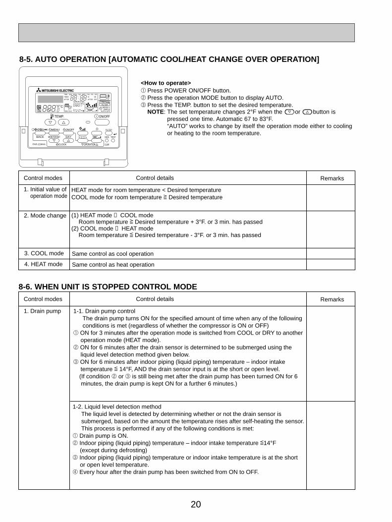
HEAT mode for room temperature < Desired temperatureCOOL mode for room temperature ] Desired temperature
(1) HEAT mode → COOL modeRoom temperature ] Desired temperature + 3°F. or 3 min. has passed
(2) COOL mode → HEAT modeRoom temperature [ Desired temperature - 3°F. or 3 min. has passed
1. Initial value of operation mode
Remarks
2. Mode change
Same control as cool operation3. COOL mode
Same control as heat operation4. HEAT mode
Control modes Control details
1-1. Drain pump controlThe drain pump turns ON for the specified amount of time when any of the following conditions is met (regardless of whether the compressor is ON or OFF)
1 ON for 3 minutes after the operation mode is switched from COOL or DRY to another operation mode (HEAT mode).
2 ON for 6 minutes after the drain sensor is determined to be submerged using the liquid level detection method given below.
3 ON for 6 minutes after indoor piping (liquid piping) temperature – indoor intake temperature [ 14°F, AND the drain sensor input is at the short or open level.(If condition 2 or 3 is still being met after the drain pump has been turned ON for 6 minutes, the drain pump is kept ON for a further 6 minutes.)
1-2. Liquid level detection methodThe liquid level is detected by determining whether or not the drain sensor is submerged, based on the amount the temperature rises after self-heating the sensor. This process is performed if any of the following conditions is met:
1 Drain pump is ON.2 Indoor piping (liquid piping) temperature – indoor intake temperature [14°F
(except during defrosting)3 Indoor piping (liquid piping) temperature or indoor intake temperature is at the short
or open level temperature.4 Every hour after the drain pump has been switched from ON to OFF.
Remarks
PAR-21MAA
ON/OFF
FILTER
CHECK
OPERATION CLEAR
TEST
TEMP.
MENU
BACK DAYMONITOR/SET
CLOCK
ON/OFF
˚F˚C
˚F˚C
ERROR CODEAFTER
TIMERTIME SUN MON TUE WED THU FRI SAT
ON
OFF
Hr
AFTER
FILTERFUNCTION
ONLY1Hr.
WEEKLYSIMPLE
AUTO OFF
8-5. AUTO OPERATION [AUTOMATIC COOL/HEAT CHANGE OVER OPERATION]
<How to operate>1 Press POWER ON/OFF button.2 Press the operation MODE button to display AUTO.3 Press the TEMP. button to set the desired temperature.
NOTE: The set temperature changes 2°F when the or button ispressed one time. Automatic 67 to 83°F.“AUTO” works to change by itself the operation mode either to coolingor heating to the room temperature.
8-6. WHEN UNIT IS STOPPED CONTROL MODE
OC340A--1.qxp 06.7.25 0:39 PM Page 20

21
9 TROUBLE SHOOTING
9-1. HOW TO CHECK THE PARTS
Parts name Check points
Disconnect the connector then measure the resistance using a tester.(Surrounding temperature 50_F~86_F)
Disconnect the connector then measure the resistance valve using a tester.
Measure the resistance between the terminals using a tester.(Surrounding temperature 68_F~86_F)
Measure the resistance between the terminals using a tester.(Surrounding temperature 68_F~86_F)
Measure the resistance after 3 minutes have passed since the power supply was intercepted.(Surrounding temperature 50_F~140_F)
Vane motor (MV)
Linear expansionvalve (LEV)
Drain pump (DP)
Drain sensor (DS)
(Refer to the next page for a detail.)
(Refer to the next page for a detail.)
Room temperaturethermistor (TH21)Liquid pipe thermistor (TH22)Gas pipe thermistor (TH23)
1
2
Red
Red
123
Normal
4.3k"~9.6k"
Abnormal
Open or short
Abnormal
Open or short
Normal
0.6k"~6.0k"
Abnormal
Open or short
Normal
150" i10%
White-Red Yellow-Brown Orange-Red Blue-Brown
NormalConnector Abnormal
300" Open or short
Normal Abnormal
319" Open or short
OrangeRedWhite
Blue
Brown
Yellow
M
Orange
Red
White
Red — Yellow
Red — Blue
Red — Orange
Red — White
Blue Yellow
Measure the resistance between the terminals using a tester.Fan motor (MF)
11
22
33
Red
White
Black
Relay connector
Protector
12/ 15/ 18/ 24
87.2"
104.1"
Abnormal
Open or short
30/ 36
32.6"
40.7"
Red-Black
White-Black
Motor terminalor
Relay connector
Normal
PLFY-P•NAMU-E
M
(Refer to the next page for a detail.)
OPEN : 266I9°FCLOSE : 176I36°F
OC340A--1.qxp 06.7.25 0:39 PM Page 21

22
4 [4
3
62
5
[3
2 [2
1 [1
[4
[3
[2
[1
Controller board
Drive circuit
Relay connector
Connector(CN60)
DC12V
Brown
Red
Blue
Orange
Yellow
White
5
1
3
4
6
M
4
6
2
3
51
Blue
Brown
Yellow
OrangeRedWhite
Linear expansion valve
<Thermistor characteristic graph>
Room temperature thermistor(TH21)Liquid pipe temperature thermistor(TH22)Gas pipe temperature thermistor(TH23)
Thermistor R0=15k' ± 3%Fixed number of B=3480k' ± 2%
Rt=15exp 3480( )
30_F 15.8k'50_F 9.6k'70_F 6.0k'80_F 4.8k'90_F 3.9k'100_F 3.2k'
Thermistor R0=6.0k' ±5%Fixed number of B=3390k' ±2%
Rt=6exp 3390( )
30_F 6.3k'50_F 3.9k'70_F 2.5k'80_F 2.0k'90_F 1.6k'100_F 1.3k'
Thermistor for lower temperature
Linear expansion valve11 Operation summary of the linear expansion valve.• Linear expansion valve open/close through stepping motor after receiving the pulse signal from the indoor controller board.• Valve position can be changed in proportion to the number of pulse signal.<Connection between the indoor controller board and the linear expansion valve>
1273+(t-32)/1.8
1273
Note : Since the number of the connector at the controller board side and the relay connector are different, follow the color ofthe lead wire.
1273+(t-32)/1.8
1273
Thermistor for drain sensor
0
10
20
30
40
50
0-20 20 40 60 80 100 120
< Thermistor for lower temperature >
Temperature (°F)
Res
ista
nce
(K"
)
20 40 60 80 100 120 140 170
< Thermistor for drain sensor >
Temperature (°F)
0
1
2
3
4
5
6
7
8
9
10
Res
ista
nce
(K"
)
OC340A--1.qxp 06.7.25 0:39 PM Page 22

23
Output(Phase)
Output
1
1
ON
2 ON
3 OFF
4 OFF
2
OFF
ON
ON
OFF
3
OFF
OFF
ON
ON
4
ON
OFF
OFF
ON
<Output pulse signal and the valve operation>
22 Linear expansion valve operation
33 Trouble shooting
D
A
E
B
C
Open
Extra tightning (80~100pulse)
Pulse number
2000 pulseOpening a valveall the way
Close
Val
ve p
ositi
on (
capa
city
)
654321
LED1k"
Symptom Check points
Operation circuit fail-ure of the microprocessor.
Disconnect the connector on the controller board, then con-nect LED for checking.
Pulse signal will be sent out for 10 seconds as soon as themain switch is turn on. If there is LED with lights on or lightsoff, it means the operation circuit is abnormal.
Countermeasures
Exchange the indoor con-troller board at drive circuitfailure.
Linear expansionvalve mechanism islocked.
Valve doesn't closecompletely (thermis-tor leaking).
Wrong connection ofthe connector orcontact failure.
To check the linear expansion valve, operate the indoor unitin fan mode and at the same time operate other indoor unitsin cooling mode, then check the pipe temperature <liquid
pipe temperature> of the indoor unit bythe outdoor multi controller board opera-tion monitor. During fan operation, linearexpansion valve is closed completely andif there are some leaking, detecting tem-perature of the thermistor will go lower. Ifthe detected temperature is much lowerthan the temperature indicated in the
remote controller, it means the valve is not closed all the way.It is not necessary to exchange the linear expansion valve, ifthe leakage is small and not making any trouble.
Thermistor(Liquid pipe)
Linearexpansionvalve
Motor will idle and make ticking noise when motor is operatedwhile the linear expansion valve is locked. This ticking soundis the sign of the abnormality.
Check the color of lead wire and missing terminal of the con-nector.
Exchange the linearexpansion vale.
Exchange the linearexpansion valve.
If large amount of thermis-tor is leaked, exchange thelinear expansion valve.
Disconnect the connectorat the controller board,then check the continuity.
Measure the resistance between the each coil (red-white,red-orange, brown-yellow, brown-blue) using a tester. It isnormal if the resistance is in the range of
Short or breakage ofthe motor coil of thelinear expansionvalve.
Closing a valve : 1 → 2 → 3 → 4 → 1Opening a valve : 4 → 3 → 2 → 1 → 4
The output pulse shifts in above order. 1. When linear expansion valve operation stops, all output phase
become OFF.2. At phase interruption or when phase does not shift in order,
motor does not rotate smoothly and motor will lock and vibrates.
When the switch is turned on, 2200 pulse closing valve signalwill be send till it goes to A point in order to define the valve position.
When the valve moves smoothly, there is no noise or vibrationoccurring from the linear expansion valve : however, when thepulse number moves from E to A or when the valve is locked,more noise can be heard than normal situation.
Noise can be detected by placing the ear against the screw driverhandle while putting the screw driver to the linear expansion valve.
150' 10%.
OC340A--1.qxp 06.7.25 0:39 PM Page 23

24
Switch Function Remarks
<At delivery>ONOFF
1 2 3 4 5 6 7 8 9 10
Address board
Operation by switch
ON OFF
Note :
w1 Fan operation at Heating mode.
w2 Heater thermo ON is operating.
w3 SW 1-7=OFF, SW 1-8=ON → Setting air flow. SW 1-7=ON, SW 1-8=ON → Indoor fan stop.
Pole
Built-in remote controller
Provided
2,500hr
Effective
Thermostat ON signal indication
Always operated while the heat in ON w1
Low w3
Setting air flow w3
Effective
Effective
Filter clogging detection
Filter cleaning
Fresh air intake
Remote indication switching
Humidifier control
Air flow set in case ofHeat thermostat OFF
Auto restart function
Power ON/OFF
Indoor unit
Not provided
100hr
Not effective
Fan output indication
Operated depends on the condition w2
Extra low w3
Depends on SW1-7
Not effective
Not effective
Cooling only
Available
Available
Available
Second setting
Horizontal angle
Effective
Not effective
5degrees
15degrees
Heat pump / Cooling only
Louver / humidifier w5
Vane
Vane swing function
Vane horizontal angle
Vane cooling limit angle setting w4
Heat 4degrees up
Superheat setting temperature w6
Sub cool setting temperature
Heat pump
Not available
Not available
Not available
First setting
Down B, C
Not effective
Effective
2degrees
10degrees
1
2
3
4
5
6
7
8
9
10
1
2
3
4
5
6
7
8
9
10
SW1Mode
Selection
SW2Capacity
codesetting
1~6
1~5
SW3FunctionSelection
SW4Unit
Selection
Indoor linear expansionvalve opening
Thermistor <intake temperature detection> position
<At delivery>ONOFF
1 2 3 4 5 6 7 8 9 10
Indoor controller board
Note : w4 At cooling mode, each angle can be used only1 hour.
w5 SW3-2 setting Only for PLFY-NAM, SW is used to change whether the humidifier functions or not. (Fixed the louver function less.)w6 SW3-9 setting PLFY-P12NAMU-E = ON P15NAMU-E = ON P18NAMU-E = OFF P24NAMU-E = OFF P30NAMU-E = OFF P36NAMU-E = OFF
<At delivery>
Indoor controller board
<At delivery>
Set while the unit is off.
Set while the unit is off.
Set while the unit is off.
Set for each capacity.
Indoor controller board
ONOFF
1 2 3 4 5 ONOFF
1 2 3 4 5
ONOFF
MODELS
PLFY-P12NAMU-E
PLFY-P30NAMU-E
PLFY-P15NAMU-E
PLFY-P36NAMU-E
PLFY-P24NAMU-E
SW 2 MODELS SW 2
1 2 3 4 5 6
ONOFF
1 2 3 4 5 6
ONOFF
1 2 3 4 5 6
ONOFF
1 2 3 4 5 6
PLFY-P18NAMU-E
ONOFF
1 2 3 4 5 6
ONOFF
1 2 3 4 5 6
9-2. FUNCTION OF DIP SWITCH
OC340A--1.qxp 06.7.25 0:39 PM Page 24

25
0
5
9
4
8 37
2
6
1 0
5
9
4
8 37
2
6
1
0
5
9
4
8 37
2
6
1 0
5
9
4
8 37
2
6
1
0
8
F
7
E
6
D 5C
4
B
3
A
2
9
1
0
8
F
7
E
6
D 5C
4
B
3
A
2
9
1
220V(208V)
240V(230V)
Switch
SWACeilingheight
selector
SWBDischarge
outletnumberselector
SWCOptionselector
Rot
ary
switc
hR
otar
y sw
itch
SW14Connection
No.setting
SW5VoltageSelection
SW111st digitaddresssetting
SW122nd digitaddresssetting
Pole
(High ceiling2)
(High ceiling1)
(Standard)
3
2
1
(2 direction)
(3 direction)
(4 direction)
2
3
4
Option
Standard Option
Standard
1~3
3
2
2
Operation by switch
Ceiling height can be changed depends on SWB setting.
Address setting should be done when M-NET Remote controller is being used.
When attach the optional high performance filter elements (multi function casement) tothe unit, be sure to attach it to the optionside in order to prevent the airflow reducing.
This is the switch to be used when the indoorunit is operated with R2 series outdoor unit as a set.
If the unit is used at the 230V area, set thevoltage to 230V.If the unit is used at the 208V, set the voltage to 208V.
Remarks
<At delivery>
Address board
<At delivery>
Address board
<At delivery>
Address board
Address can be set while the unit is stopped.
Address board
<At delivery>
Address board
<At delivery>
Address board
321
234
SW12
10
SW11
1SW12 SW11
SW14
SW14
<At delivery>
220V(208V)
240V(230V)
SWB
PLFY-P12, P15, P18, P24NAMU-E
4 direction
3 direction
2 direction
4
3
2
8.9
9.8
10.8
9.8
10.8
11.5
11.5
11.5
—
SWA 1
Standard
(Unit : feet)
(Unit : feet)
Highceiling1
Highceiling2
2 3
SWB
PLFY-P30, P36NAMU-E
4 direction
3 direction
2 direction
4
3
2
10.5
11.8
13.1
11.8
13.1
13.8
13.8
13.8
—
SWA 1
StandardHigh
ceiling1High
ceiling2
2 3
OC340A--1.qxp 06.7.25 0:39 PM Page 25
26
10 DISASSEMBLY PROCEDURE
OPERATING PROCEDURE
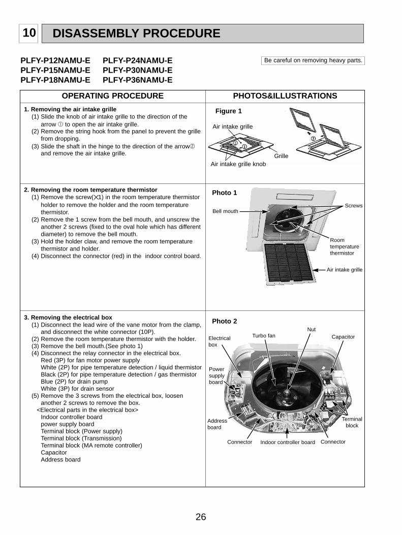
1. Removing the air intake grille(1) Slide the knob of air intake grille to the direction of the
arrow 1 to open the air intake grille.(2) Remove the string hook from the panel to prevent the grille
from dropping.(3) Slide the shaft in the hinge to the direction of the arrow2
and remove the air intake grille.
3. Removing the electrical box(1) Disconnect the lead wire of the vane motor from the clamp,
and disconnect the white connector (10P).(2) Remove the room temperature thermistor with the holder.(3) Remove the bell mouth.(See photo 1)(4) Disconnect the relay connector in the electrical box.
Red (3P) for fan motor power supplyWhite (2P) for pipe temperature detection / liquid thermistorBlack (2P) for pipe temperature detection / gas thermistorBlue (2P) for drain pumpWhite (3P) for drain sensor
(5) Remove the 3 screws from the electrical box, loosenanother 2 screws to remove the box.
<Electrical parts in the electrical box>Indoor controller boardpower supply boardTerminal block (Power supply)Terminal block (Transmission)Terminal block (MA remote controller)CapacitorAddress board
PLFY-P12NAMU-E PLFY-P24NAMU-EPLFY-P15NAMU-E PLFY-P30NAMU-EPLFY-P18NAMU-E PLFY-P36NAMU-E
Be careful on removing heavy parts.
Photo 2
Figure 1
Air intake grille
Grille
Nut
Air intake grille knob
2. Removing the room temperature thermistor(1) Remove the screw(1) in the room temperature thermistor
holder to remove the holder and the room temperaturethermistor.
(2) Remove the 1 screw from the bell mouth, and unscrew theanother 2 screws (fixed to the oval hole which has differentdiameter) to remove the bell mouth.
(3) Hold the holder claw, and remove the room temperaturethermistor and holder.
(4) Disconnect the connector (red) in the indoor control board.
Bell mouth
Indoor controller board Connector
Terminalblock
Photo 1
Screws
Roomtemperaturethermistor
Air intake grille
Connector
Electricalbox
Powersupplyboard
Turbo fan
Addressboard
Capacitor
PHOTOS&ILLUSTRATIONS
OC340A--1.qxp 06.7.25 0:39 PM Page 26
27
OPERATING PROCEDURE PHOTOS&ILLUSTRATIONS
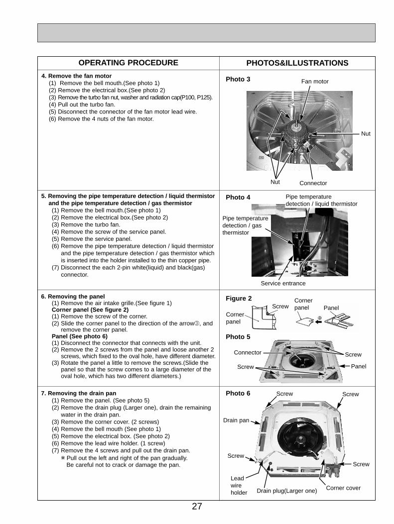
5. Removing the pipe temperature detection / liquid thermistorand the pipe temperature detection / gas thermistor(1) Remove the bell mouth.(See photo 1)(2) Remove the electrical box.(See photo 2)(3) Remove the turbo fan.(4) Remove the screw of the service panel.(5) Remove the service panel.(6) Remove the pipe temperature detection / liquid thermistor
and the pipe temperature detection / gas thermistor whichis inserted into the holder installed to the thin copper pipe.
(7) Disconnect the each 2-pin white(liquid) and black(gas)connector.
6. Removing the panel(1) Remove the air intake grille.(See figure 1)Corner panel (See figure 2)(1) Remove the screw of the corner.(2) Slide the corner panel to the direction of the arrow3, and
remove the corner panel.Panel (See photo 6)(1) Disconnect the connector that connects with the unit.(2) Remove the 2 screws from the panel and loose another 2
screws, which fixed to the oval hole, have different diameter.(3) Rotate the panel a little to remove the screws.(Slide the
panel so that the screw comes to a large diameter of theoval hole, which has two different diameters.)
Photo 6
Photo 5
Photo 4
4. Remove the fan motor(1) Remove the bell mouth.(See photo 1)(2) Remove the electrical box.(See photo 2)(3) Remove the turbo fan nut, washer and radiation cap(P100, P125).(4) Pull out the turbo fan.(5) Disconnect the connector of the fan motor lead wire.(6) Remove the 4 nuts of the fan motor.
Photo 3 Fan motor
Nut Connector
Service entrance
7. Removing the drain pan(1) Remove the panel. (See photo 5)(2) Remove the drain plug (Larger one), drain the remaining
water in the drain pan.(3) Remove the corner cover. (2 screws)(4) Remove the bell mouth (See photo 1)(5) Remove the electrical box. (See photo 2)(6) Remove the lead wire holder. (1 screw)(7) Remove the 4 screws and pull out the drain pan.
w Pull out the left and right of the pan gradually.Be careful not to crack or damage the pan.
Figure 2
Cornerpanel
ScrewCornerpanel Panel
PanelScrew
Connector Screw
Screw Screw
ScrewScrew
Drain pan
Drain plug(Larger one) Corner cover
Leadwireholder
Pipe temperaturedetection / liquid thermistor
Pipe temperaturedetection / gasthermistor
Nut
OC340A--1.qxp 06.7.25 0:39 PM Page 27

28
OPERATING PROCEDURE PHOTOS&ILLUSTRATIONS
9. Removing the heat exchanger(1) Remove the panel. (See photo 5)(2) Remove the bell mouth. (See photo 1)(3) Remove the electrical box. (See photo 2)(4) Remove the drain pan. (See photo 6)(5) Remove the turbo fan. (See photo 3)(6) Remove the 3 screws of the piping cover, and pull out
piping cover.(7) Remove the 4 screws of the outer wall cover, and pull out
the outer wall cover.(8) Remove the screw of the coil support.(9) Remove the 2 screws of the coil.
(10) Pull out the heat exchanger.
8. Removing the drain pump and drain sensor(1) Remove the panel. (See photo 5)(2) Remove the bell mouth. (See photo 1)(3) Remove the electrical box. (See photo 2)(4) Remove the drain pan. (See photo 6)(5) Remove the 3 screws of the drain pump.(6) Cut the drain hose band, pull out the drain hose from the
drain pump.(7) Pull out the drain pump.(8) Remove the drain sensor and the holder.
Photo 7
Screw
Screw
Drain sensor
Drain pumpDrain hose
Fixing band
Photo 8
Photo 9
Heat exchanger
Coilsupport
Coil screwsCoil support
Coilsupport
Screw
Outer wall cover Piping coverScrews ofpiping cover
OC340A--1.qxp 06.7.25 0:39 PM Page 28
29
ON/OFF TEMP.
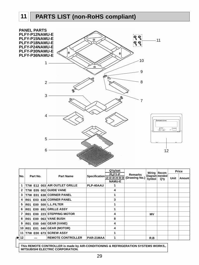
PARTS LIST (non-RoHS compliant)11
1
2
3
4
5
6
7
8
9
10
11
12
1
4
1
3
1
1
4
8
4
4
1
1
MV
R.B
AIR OUTLET GRILLE
GUIDE VANE
CORNER PANEL
CORNER PANEL
L.L.FILTER
GRILLE ASSY
STEPPING MOTOR
VANE BUSH
GEAR (VANE)
GEAR (MOTOR)
SCREW ASSY
REMOTE CONTROLLER
PLP-40AAU
PAR-21MAA
No. Part No. Part Name Specification
Q'ty/set Price
Unit AmountRemarks
(Drawing No.)
WiringDiagramSymbol
Recom-mended
Q'tyPLFY-P
12/ 15/ 18/ 24/ 30/ 36NAMU-E
T7W E12 003
T7W E05 002
T7W E01 638
R01 E03 638
R01 E00 500
R01 E00 691
R01 E00 223
R01 E00 063
R01 E00 040
R01 E01 040
T7W E00 673
—
This REMOTE CONTROLLER is made by AIR-CONDITIONING & REFRIGERATION SYSTEMS WORKS,. MITSUBISHI ELECTRIC CORPORATION.
1
2
3
4
5
6
7
8
9
10
12
PANEL PARTSPLFY-P12NAMU-EPLFY-P15NAMU-EPLFY-P18NAMU-EPLFY-P24NAMU-EPLFY-P30NAMU-EPLFY-P36NAMU-E
11
OC340A--1.qxp 06.7.25 0:39 PM Page 29

30
1
2
3
4
5
6
7
8
9
1
1
1
1
1
1
1
1
4
1
1
1
1
1
1
1
1
4
LEV
LEV
TH23
TH22
MF
MF
GAS
LIQUID
(D17D6P70MS)
(D176P110MS)
TURBO FAN
TURBO FAN
SPL WASHER
HEAT EXCHANGER
HEAT EXCHANGER
HEAT EXCHANGER
HEAT EXCHANGER
HEAT EXCHANGER
LINEAR EXPANSION VALVE
LINEAR EXPANSION VALVE
PIPE TEMPERATURE THERMISTOR
PIPE TEMPERATURE THERMISTOR
MOTOR CAP
FAN MOTOR
FAN MOTOR
RUBBER MOUNT
No. Part No. Part Name Specification
Q'ty/set Price
Unit AmountRemarks
(Drawing No.)
WiringDiagramSymbol
Recom-mended
Q'tyPLFY-P · NAMU-E
12 18
1
1
1
1
1
1
1
1
4
15
1
1
1
1
1
1
1
1
4
24
1
1
1
1
1
1
1
1
4
30
1
1
1
1
1
1
1
1
4
36
R01 E10 114
R01 E11 114
R01 08K 097
T7W K16 480
T7W K17 480
T7W K18 480
T7W K19 480
T7W K20 480
R01 E56 401
R01 E57 401
T7W E06 202
R01 E00 202
R01 E00 122
T7W E12 762
T7W E08 762
R01 A41 105
FUNCTIONAL PARTSPLFY-P12NAMU-EPLFY-P15NAMU-EPLFY-P18NAMU-EPLFY-P24NAMU-EPLFY-P30NAMU-EPLFY-P36NAMU-E
1
2
3
4
5
6
89
7
OC340A--1.qxp 06.7.25 0:39 PM Page 30
31
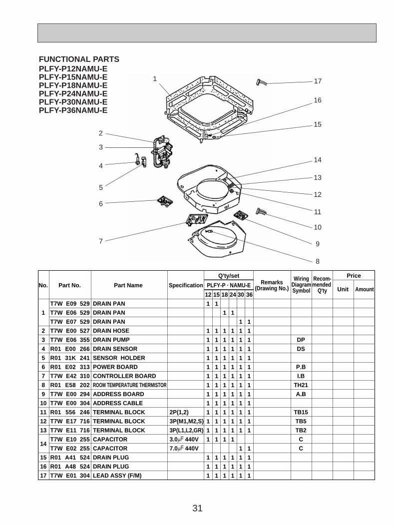
FUNCTIONAL PARTSPLFY-P12NAMU-EPLFY-P15NAMU-EPLFY-P18NAMU-EPLFY-P24NAMU-EPLFY-P30NAMU-EPLFY-P36NAMU-E
1
2
3
4
5
6
7
8
9
10
11
12
13
14
15
16
17
1
1
1
1
1
1
1
1
1
1
1
1
1
1
1
1
1
1
1
1
1
1
1
1
1
1
1
1
1
1
1
1
1
1
1
1
1
1
1
1
1
1
1
1
1
1
1
1
1
1
1
1
1
1
1
1
1
1
1
1
1
1
1
1
1
1
1
1
1
1
1
1
1
1
1
1
1
1
1
1
1
1
1
1
1
1
1
1
1
1
1
1
1
1
1
1
1
1
1
1
1
1
DP
DS
P.B
I.B
TH21
A.B
TB15
TB5
TB2
C
C
DRAIN PAN
DRAIN PAN
DRAIN PAN
DRAIN HOSE
DRAIN PUMP
DRAIN SENSOR
SENSOR HOLDER
POWER BOARD
CONTROLLER BOARD
ROOM TEMPERATURE THERMISTOR
ADDRESS BOARD
ADDRESS CABLE
TERMINAL BLOCK
TERMINAL BLOCK
TERMINAL BLOCK
CAPACITOR
CAPACITOR
DRAIN PLUG
DRAIN PLUG
LEAD ASSY (F/M)
2P(1,2)
3P(M1,M2,S)
3P(L1,L2,GR)
3.0+ 440V
7.0+ 440V
No. Part No. Part Name Specification
Q'ty/set Price
Unit AmountRemarks
(Drawing No.)
WiringDiagramSymbol
Recom-mended
Q'tyPLFY-P · NAMU-E
12 1815 24 30 36
T7W E09 529
T7W E06 529
T7W E07 529
T7W E00 527
T7W E06 355
R01 E00 266
R01 31K 241
R01 E02 313
T7W E42 310
R01 E58 202
T7W E00 294
T7W E00 304
R01 556 246
T7W E17 716
T7W E11 716
T7W E10 255
T7W E02 255
R01 A41 524
R01 A48 524
T7W E01 304
1
3
4
5
6
7
8
12
13
14
15
16
10
9
11
17
2
OC340A--2.qxp 06.7.25 0:43 PM Page 31

32
12 RoHS PARTS LIST
ON/OFF TEMP.
1
2
3
4
5
6
7
8
9
10
11
12
1
4
1
3
1
1
4
8
4
4
1
1
MV
R.B
AIR OUTLET GRILLE
GUIDE VANE
CORNER PANEL
CORNER PANEL
L.L.FILTER
GRILLE ASSY
STEPPING MOTOR
VANE BUSH
GEAR (VANE)
GEAR (MOTOR)
SCREW ASSY
REMOTE CONTROLLER
PLP-40AAU
PAR-21MAA
No.
G
G
G
G
G
G
G
G
G
G
G
G
Ro
HS
Part No. Part Name Specification
Q'ty/set Price
Unit AmountRemarks
(Drawing No.)
WiringDiagramSymbol
Recom-mended
Q'tyPLFY-P
12/ 15/ 18/ 24/ 30/ 36NAMU-E
T7W E18 003
T7W E09 002
T7W E02 638
R01 E14 638
R01 E13 500
R01 E44 691
R01 E17 223
R01 E02 063
R01 E03 040
R01 E04 040
T7W E01 673
—
This REMOTE CONTROLLER is made by AIR-CONDITIONING & REFRIGERATION SYSTEMS WORKS,. MITSUBISHI ELECTRIC CORPORATION.
1
2
3
4
5
6
7
8
9
10
12
PANEL PARTSPLFY-P12NAMU-EPLFY-P15NAMU-EPLFY-P18NAMU-EPLFY-P24NAMU-EPLFY-P30NAMU-EPLFY-P36NAMU-E
11
OC340A--2.qxp 06.7.25 0:43 PM Page 32

33
1
2
3
4
5
6
7
8
9
1
1
1
1
1
1
1
1
4
1
1
1
1
1
1
1
1
4
LEV
LEV
TH23
TH22
MF
MF
GAS
LIQUID
(D17D6P70MS)
(D176P110MS)
TURBO FAN
TURBO FAN
SPL WASHER
HEAT EXCHANGER
HEAT EXCHANGER
HEAT EXCHANGER
HEAT EXCHANGER
HEAT EXCHANGER
LINEAR EXPANSION VALVE
LINEAR EXPANSION VALVE
PIPE TEMPERATURE THERMISTOR
PIPE TEMPERATURE THERMISTOR
MOTOR CAP
FAN MOTOR
FAN MOTOR
RUBBER MOUNT
No.
G
G
G
G
G
G
G
G
G
G
G
G
G
G
G
G
Ro
HS
Part No. Part Name Specification
Q'ty/set Price
Unit AmountRemarks
(Drawing No.)
WiringDiagramSymbol
Recom-mended
Q'tyPLFY-P · NAMU-E
12 18
1
1
1
1
1
1
1
1
4
15
1
1
1
1
1
1
1
1
4
24
1
1
1
1
1
1
1
1
4
30
1
1
1
1
1
1
1
1
4
36
R01 E28 114
R01 E29 114
R01 09K 097
T7W H10 480
T7W H11 480
T7W H12 480
T7W H13 480
T7W K32 480
R01 H07 401
R01 E88 401
R01 H11 202
R01 H05 202
R01 E03 122
T7W E27 762
T7W E28 762
R01 A51 105
FUNCTIONAL PARTSPLFY-P12NAMU-EPLFY-P15NAMU-EPLFY-P18NAMU-EPLFY-P24NAMU-EPLFY-P30NAMU-EPLFY-P36NAMU-E
1
2
3
4
5
6
89
7
OC340A--2.qxp 06.7.25 0:43 PM Page 33

34
FUNCTIONAL PARTSPLFY-P12NAMU-EPLFY-P15NAMU-EPLFY-P18NAMU-EPLFY-P24NAMU-EPLFY-P30NAMU-EPLFY-P36NAMU-E
1
2
3
4
5
6
7
8
9
10
11
12
13
14
15
16
17
1
1
1
1
1
1
1
1
1
1
1
1
1
1
1
1
1
1
1
1
1
1
1
1
1
1
1
1
1
1
1
1
1
1
1
1
1
1
1
1
1
1
1
1
1
1
1
1
1
1
1
1
1
1
1
1
1
1
1
1
1
1
1
1
1
1
1
1
1
1
1
1
1
1
1
1
1
1
1
1
1
1
1
1
1
1
1
1
1
1
1
1
1
1
1
1
1
1
1
1
1
1
DP
DS
P.B
I.B
TH21
A.B
TB15
TB5
TB2
C
C
DRAIN PAN
DRAIN PAN
DRAIN PAN
DRAIN HOSE
DRAIN PUMP
DRAIN SENSOR
SENSOR HOLDER
POWER BOARD
CONTROLLER BOARD
ROOM TEMPERATURE THERMISTOR
ADDRESS BOARD
ADDRESS CABLE
TERMINAL BLOCK
TERMINAL BLOCK
TERMINAL BLOCK
CAPACITOR
CAPACITOR
DRAIN PLUG
DRAIN PLUG
LEAD ASSY (F/M)
2P(1,2)
3P(M1,M2,S)
3P(L1,L2,GR)
3.0+ 440V
7.0+ 440V
No.
G
G
G
G
G
G
G
G
G
G
G
G
G
G
G
G
G
G
G
G
Ro
HS
Part No. Part Name Specification
Q'ty/set Price
Unit AmountRemarks
(Drawing No.)
WiringDiagramSymbol
Recom-mended
Q'tyPLFY-P · NAMU-E
12 1815 24 30 36
T7W E26 529
T7W E27 529
T7W E28 529
T7W E02 527
T7W E13 355
R01 E10 266
R01 32K 241
R01 E38 313
T7W E57 310
R01 H12 202
T7W E01 294
T7W E04 304
R01 E21 246
R01 E27 246
T7W E41 716
T7W E15 255
T7W E14 255
R01 A01 524
R01 A00 524
T7W E05 304
1
3
4
5
6
7
8
12
13
14
15
16
10
9
11
17
2
OC340A--2.qxp 06.7.25 0:43 PM Page 34

35
OPTIONAL PARTS13
13-1. MULTI FUNCTION CASEMENT
Part No. PAC-SG03TM-E
13-2. AIR OUTLET SHUTTER PLATE (20 SETS)
Part No. PAC-SG06SP-E
13-3. HIGH EFFICIENCY FILTER ELEMENT (PAC-SG03TM-E IS REQUIRED)
Part No. PAC-SG01KF
OC340A--2.qxp 06.7.25 0:43 PM Page 35

cCopyright 2005 MITSUBISHI ELECTRIC ENGINEERING CO., LTD.Distributed in Aug. 2006 No. OC340 REVISED EDITION-A PDF 9Distributed in Jun. 2005 No. OC340 PDF 10Made in Japan
New publication, effective Aug. 2006Specifications subject to change without notice
HEAD OFFICE : TOKYO BLDG., 2-7-3, MARUNOUCHI, CHIYODA-KU, TOKYO 100-8310, JAPAN
OC340A--2.qxp 06.7.25 0:43 PM Page 36