MODEL PLFY-P-NFMU-E...
28
AIR CONDITIONING SYSTEMS PLFY-P-NFMU-E PLFY-EP-NEMU-E(1) MODEL
Transcript of MODEL PLFY-P-NFMU-E...

AIR CONDITIONING SYSTEMS
PLFY-P-NFMU-EPLFY-EP-NEMU-E(1)
MODEL

PLFY-P-NFMU-E, PLFY-EP-NEMU-E(1)
MEES18K084 1
CONTENTS Ceiling cassette (4-way flow type)
I.Ceiling cassette (4-way flow type)
1. SPECIFICATIONS.................................................................................................................................... 2
2. EXTERNAL DIMENSIONS ....................................................................................................................... 7
3. CENTER OF GRAVITY ............................................................................................................................ 9
4. ELECTRICAL WIRING DIAGRAMS ......................................................................................................... 10
5. SOUND LEVELS ...................................................................................................................................... 12
5-1. Sound levels .................................................................................................................................... 125-2. NC curves ........................................................................................................................................ 12
6. TEMPERATURE/AIRFLOW DISTRIBUTIONS......................................................................................... 14
6-1. Temperature distributions ................................................................................................................ 146-2. Airflow distributions.......................................................................................................................... 17
7. OUTDOOR AIR INTAKE AMOUNT & STATIC PRESSURE.................................................................... 20
8. ELECTRICAL CHARACTERISTICS......................................................................................................... 22
9. OPTIONAL PARTS................................................................................................................................... 23
9-1. Optional parts line up for the Indoor unit.......................................................................................... 239-2. Air outlet shutter plate...................................................................................................................... 239-3. High efficiency filter element ............................................................................................................ 249-4. Multi-function casement................................................................................................................... 249-5. i-see Sensor corner panel................................................................................................................ 249-6. Wireless signal receiver................................................................................................................... 259-7. Flange for fresh air intake ................................................................................................................ 259-8. External heater adapter ................................................................................................................... 26
0000005093.BOOK 1 ページ 2019年1月25日 金曜日 午後3時57分

MEES18K084
PL
FY
-P-N
FM
U-E
, E
P-N
EM
U-E
(1)
2
1. SPECIFICATIONS Ceiling cassette (4-way flow type)
I.Ceiling cassette (4-way flow type)1. SPECIFICATIONS
Model PLFY-P05NFMU-E PLFY-P08NFMU-E PLFY-P12NFMU-E
Power source 1-phase 208-230 V 60Hz
Cooling capacity *1 BTU / h 5,000 8,000 12,000
(Nominal) *1 kW 1.4 2.3 3.5
Power input kW 0.02 0.02 0.02
Current input A 0.19 0.22 0.23
Heating capacity *2 BTU / h 5,600 9,000 13,500
(Nominal) *2 kW 1.6 2.6 3.9
Power input kW 0.02 0.02 0.02
Current input A 0.14 0.17 0.18
External finish Galvanized steel sheet
External dimension H × W × D in. 8-3/16 × 22-7/16 × 22-7/16
mm 208 × 570 × 570
Net weight lbs (kg) 28.9 (13.1) 31.3 (14.2)
Decoration Model SLP-18FAU
panel External finish MUNSELL (1.0Y 9.2/0.2)
Dimension in. 13/32 × 24-19/32 × 24-19/32
H × W × D mm 10 × 625 × 625
Net Weight lbs (kg) 5.3 (2.4)
Heat exchanger Cross fin (Aluminum fin and copper tube)
FAN Type × Quantity Turbo fan × 1
External in.WG 0
static press Pa 0
Motor type DC motor
Motor output kW 0.05
Driving mechanism Direct-driven
Air flow rate cfm 230-265-280 230-280-315 245-280-335
(Low-Mid-High) m3 / min 6.5-7.5-8.0 6.5-8.0-9.0 7.0-8.0-9.5
L / s 108-125-133 108-133-150 117-133-158
Sound pressure level (Low-Mid-High)dB <A> 26-28-30 26-30-33 26-30-34
(measured in anechoic room)
Insulation material PS
Air filter PP honeycomb fabric (long life type)
Protection device Fuse
Refrigerant control device LEV
Connectable outdoor unit R410A CITY MULTI
Refrigerant Liquid (R410A) in. (mm) 1/4 (6.35) Flare
piping diameter Gas (R410A) in. (mm) 1/2 (12.7) Flare
Field drain pipe size in. (mm) O.D.1-1/4 (32) (PVC pipe VP-25 connectable)
Drawing External RK01B327
Wiring BH79N033H01
Refrigerant cycle -
Standard Document Installation Manual, Installation Book
attachment Accessory -
Optional parts Decoration panel SLP-18FAU
3D i-see Sensor panel SLP-18FAEU SLP-18FAEU SLP-18FAEU
3D i-see Sensor corner panel PAC-SF1ME-E PAC-SF1ME-E PAC-SF1ME-E
Wireless signal receiver PAR-SF9FA-E PAR-SF9FA-E PAR-SF9FA-E
Remarks *PLFY-P-NFMU-E should be used with SLP-18FAU/SLP-18FAEU.
* Details on foundation work, duct work, insulation work, electrical wiring, power source switch, and other items shall be referred to the Installation Manual.
* Due to continuing improvement, above specifications may be subject to change without notice.
Notes: Unit convertor
1.Nominal cooling conditions' kcal/h = kW × 860
Indoor:80°FDB/67°FWB(26.7°CDB/19.4°CWB), Outdoor:95°FDB(35°CDB) BTU/h = kW × 3,412
Pipe length:25ft.(7.6m), Level difference:0ft.(0m) cfm = m3/min × 35.31
2.Nominal heating conditions lbs = kg / 0.4536
Indoor:70°FDB(21.1°CDB), Outdoor:47°FDB/43°FWB(8.3°CDB/6.1°CWB)
Pipe length:25ft.(7.6m), Level difference:0ft.(0m) *Above specification data is
subject to rounding variation.
0000005093.BOOK 2 ページ 2019年1月25日 金曜日 午後3時57分

MEES18K084
PL
FY
-P-N
FM
U-E
, EP
-NE
MU
-E(1
)
3
1. SPECIFICATIONS Ceiling cassette (4-way flow type)
Model PLFY-P15NFMU-E PLFY-P18NFMU-E
Power source 1-phase 208-230 V 60Hz
Cooling capacity *1 BTU / h 15,000 18,000
(Nominal) *1 kW 4.3 5.2
Power input kW 0.03 0.04
Current input A 0.28 0.40
Heating capacity *2 BTU / h 17,000 20,000
(Nominal) *2 kW 4.9 5.8
Power input kW 0.03 0.04
Current input A 0.23 0.35
External finish Galvanized steel sheet
External dimension H × W × D in. 8-3/16 × 22-7/16 × 22-7/16
mm 208 × 570 × 570
Net weight lbs (kg) 31.3 (14.2)
Decoration Model SLP-18FAU
panel External finish MUNSELL (1.0Y 9.2/0.2)
Dimension in. 13/32 × 24-19/32 × 24-19/32
H × W × D mm 10 × 625 × 625
Net Weight lbs (kg) 5.3 (2.4)
Heat exchanger Cross fin (Aluminum fin and copper tube)
FAN Type × Quantity Turbo fan × 1
External in.WG 0
static press Pa 0
Motor type DC motor
Motor output kW 0.05
Driving mechanism Direct-driven
Airflow rate cfm 265-315-390 315-390-460
(Low-Mid-High) m3 / min 7.5-9.0-11.0 9.0-11.0-13.0
L / s 125-150-183 150-183-217
Sound pressure level (Low-Mid-High)dB <A> 28-33-39 33-39-43
(measured in anechoic room)
Insulation material PS
Air filter PP honeycomb fabric (long life type)
Protection device Fuse
Refrigerant control device LEV
Connectable outdoor unit R410A CITY MULTI
Refrigerant Liquid (R410A) in. (mm) 1/4 (6.35) Flare
piping diameter Gas (R410A) in. (mm) 1/2 (12.7) Flare
Field drain pipe size in. (mm) O.D.1-1/4 (32) (PVC pipe VP-25 connectable)
Drawing External RK01B327
Wiring BH79N033H01
Refrigerant cycle -
Standard Document Installation Manual, Installation Book
attachment Accessory -
Optional parts Decoration panel SLP-18FAU
3D i-see Sensor panel SLP-18FAEU SLP-18FAEU
3D i-see Sensor corner panel PAC-SF1ME-E PAC-SF1ME-E
Wireless signal receiver PAR-SF9FA-E PAR-SF9FA-E
Remarks *PLFY-P-NFMU-E should be used with SLP-18FAU/SLP-18FAEU.
* Details on foundation work, duct work, insulation work, electrical wiring, power source switch, and other items shall be referred to the Installation Manual.
* Due to continuing improvement, above specifications may be subject to change without notice.
Notes: Unit convertor
1.Nominal cooling conditions' kcal/h = kW × 860
Indoor:80°FDB/67°FWB(26.7°CDB/19.4°CWB), Outdoor:95°FDB(35°CDB) BTU/h = kW × 3,412
Pipe length:25ft.(7.6m), Level difference:0ft.(0m) cfm = m3/min × 35.31
2.Nominal heating conditions lbs = kg / 0.4536
Indoor:70°FDB(21.1°CDB), Outdoor:47°FDB/43°FWB(8.3°CDB/6.1°CWB)
Pipe length:25ft.(7.6m), Level difference:0ft.(0m) *Above specification data is
subject to rounding variation.
0000005093.BOOK 3 ページ 2019年1月25日 金曜日 午後3時57分

MEES18K084
PL
FY
-P-N
FM
U-E
, E
P-N
EM
U-E
(1)
4
1. SPECIFICATIONS Ceiling cassette (4-way flow type)
Model PLFY-EP06NEMU-E PLFY-EP08NEMU-E PLFY-EP12NEMU-E
Power source 1-phase 208-230 V 60Hz
Cooling capacity *1 BTU/h 6,000 8,000 12,000
*1 kW 1.8 2.4 3.5
Power input kW 0.02 0.03 0.03
Current input A 0.19 0.31 0.31
Heating capacity *2 BTU/h 6,700 9,000 13,500
*2 kW 2.0 2.7 4.0
Power input kW 0.02 0.02 0.02
Current input A 0.14 0.26 0.26
External finish Galvanized steel sheet
External dimension H × W × D inch 10-3/16 × 33-3/32 × 33-3/32 10-3/16 × 33-3/32 × 33-3/32 10-3/16 × 33-3/32 × 33-3/32
mm 258 × 840 × 840 258 × 840 × 840 258 × 840 × 840
Net weight lbs (kg) 46 (21) 46 (21) 46 (21)
Decoration panel Model PLP-40EAEU PLP-40EAEU PLP-40EAEU
External finish MUNSELL (6.4Y 8.9/0.4)
Dimension in. 1-9/16 × 37-13/32 × 37-13/32 1-9/16 × 37-13/32 × 37-13/32 1-9/16 × 37-13/32 × 37-13/32
H × W × D mm 40 × 950 × 950 40 × 950 × 950 40 × 950 × 950
Net weight lbs (kg) 11 (5) 11 (5) 11 (5)
Heat exchanger Cross fin
FAN Type × Quantity Turbo fan × 1 Turbo fan × 1 Turbo fan × 1
External static press. in.WG 0.000 (208V) 0.000 (208V) 0.000 (208V)
Pa 0 0 0
in.WG 0.000 (230V) 0.000 (230V) 0.000 (230V)
Pa 0 0 0
Motor Type DC motor
Motor output kW 0.05 0.05 0.05
Driving mechanism Direct-driven
Air flow rate (Low-Mid2-Mid1-High) (Low-Mid2-Mid1-High) (Low-Mid2-Mid1-High)
cfm 300 - 424 - 459 - 494 494 - 530 - 565 - 600 494 - 530 - 565 - 600
m3/min 8.5 - 12 - 13 - 14 14 - 15 - 16 - 17 14 - 15 - 16 - 17
L/s 142 - 200 - 217 - 233 233 - 250 - 267 - 283 233 - 250 - 267 - 283
Sound pressure level (measured in anechoic room) (Low-Mid2-Mid1-High) (Low-Mid2-Mid1-High) (Low-Mid2-Mid1-High)
dB <A> 19 - 23 - 25 - 27 27 - 29 - 30 - 31 27 - 29 - 30 - 31
Insulation material PS
Air filter PP honeycomb (long life filter, anti-bacterial type)
Protection device Fuse
Refrigerant control device LEV
Connectable outdoor unit R410A CITY MULTI
Refrigerant piping Liquid (R410A) inch (mm) 1/4 (6.35) Flare 1/4 (6.35) Flare 1/4 (6.35) Flare
diameter Gas (R410A) inch (mm) 1/2 (12.7) Flare 1/2 (12.7) Flare 1/2 (12.7) Flare
Field drain pipe size inch (mm) O.D. 1-1/4(32) O.D. 1-1/4(32) O.D. 1-1/4(32)
Drawing External BK01V542 BK01V542 BK01V542
Wiring RG79Y808 RG79Y808 RG79Y808
Refrigerant cycle - - -
Standard attachment Document Installation Manual, Instruction Book
Accessory
Optional parts 3D i-see Sensor panel PLP-40EAEU PLP-40EAEU PLP-40EAEU
Air outlet shutter plate PAC-SJ37SP-E PAC-SJ37SP-E PAC-SJ37SP-E
High efficiency filter element PAC-SH59KF-E PAC-SH59KF-E PAC-SH59KF-E
Multi-function casement PAC-SJ41TM-E PAC-SJ41TM-E PAC-SJ41TM-E
Wireless signal receiver PAR-SR3LA-E PAR-SR3LA-E PAR-SR3LA-E
External heater adapter PAC-YU25HT PAC-YU25HT PAC-YU25HT
Duct flange for fresh air intake PAC-SH65OF-E PAC-SH65OF-E PAC-SH65OF-E
Remarks * Details on foundation work, duct work, insulation work, electrical wiring, power source switch, and other items shall be referred to the Installation Manual.
* Due to continuing improvement, above specification may be subject to change without notice.
Notes: *1 Nominal cooling conditions *2 Nominal heating conditions Unit converter
Indoor: 80degF D.B. / 67degF W.B. 70degF D.B. kcal/h = kW x 860
(26.7degC D.B. / 19.4degC W.B.) (21.1degC D.B.) BTU/h = kW x 3,412
Outdoor: 95degF D.B. 47degF D.B. / 43degF W.B. cfm = m3/min x 35.31
(35degC D.B.) (8.3degC D.B. / 6.1degC W.B.) lbs = kg / 0.4536
Pipe length: 25 ft. (7.6 m) 25 ft. (7.6 m)
Level difference: 0 ft. (0 m) 0 ft. (0 m) *Above specification data is
subject to rounding variation.
0000005093.BOOK 4 ページ 2019年1月25日 金曜日 午後3時57分

MEES18K084
PL
FY
-P-N
FM
U-E
, EP
-NE
MU
-E(1
)
5
1. SPECIFICATIONS Ceiling cassette (4-way flow type)
Model PLFY-EP15NEMU-E PLFY-EP18NEMU-E1 PLFY-EP24NEMU-E
Power source 1-phase 208-230 V 60Hz
Cooling capacity *1 BTU/h 15,000 18,000 24,000
*1 kW 4.4 5.3 7.0
Power input kW 0.03 0.04 0.04
Current input A 0.31 0.43 0.43
Heating capacity *2 BTU/h 17,000 20,000 27,000
*2 kW 5.0 5.9 7.9
Power input kW 0.02 0.04 0.04
Current input A 0.26 0.38 0.38
External finish Galvanized steel sheet
External dimension H × W × D inch 10-3/16 × 33-3/32 × 33-3/32 11-3/4 × 33-3/32 × 33-3/32 11-3/4 × 33-3/32 × 33-3/32
mm 258 × 840 × 840 298 × 840 × 840 298 × 840 × 840
Net weight lbs (kg) 46 (21) 55 (25) 55 (25)
Decoration panel Model PLP-40EAEU PLP-40EAEU PLP-40EAEU
External finish MUNSELL (6.4Y 8.9/0.4)
Dimension in. 1-9/16 × 37-13/32 × 37-13/32 1-9/16 × 37-13/32 × 37-13/32 1-9/16 × 37-13/32 × 37-13/32
H × W × D mm 40 × 950 × 950 40 × 950 × 950 40 × 950 × 950
Net weight lbs (kg) 11 (5) 11 (5) 11 (5)
Heat exchanger Cross fin
FAN Type × Quantity Turbo fan × 1 Turbo fan × 1 Turbo fan × 1
External static press. in.WG 0.000 (208V) 0.000 (208V) 0.000 (208V)
Pa 0 0 0
in.WG 0.000 (230V) 0.000 (230V) 0.000 (230V)
Pa 0 0 0
Motor Type DC motor
Motor output kW 0.05 0.12 0.12
Driving mechanism Direct-driven
Air flow rate (Low-Mid2-Mid1-High) (Low-Mid2-Mid1-High) (Low-Mid2-Mid1-High)
cfm 530 - 547 - 565 - 600 636 - 671 - 742 - 812 636 - 671 - 742 - 812
m3/min 15 - 15.5 - 16 - 17 18 - 19 - 21 - 23 18 - 19 - 21 - 23
L/s 250 - 258 - 267 - 283 300 - 317 - 350 - 383 300 - 317 - 350 - 383
Sound pressure level (measured in anechoic room) (Low-Mid2-Mid1-High) (Low-Mid2-Mid1-High) (Low-Mid2-Mid1-High)
dB <A> 28 - 29 - 30 - 31 28 - 30 - 32 - 34 28 - 30 - 32 - 34
Insulation material PS
Air filter PP honeycomb (long life filter, anti-bacterial type)
Protection device Fuse
Refrigerant control device LEV
Connectable outdoor unit R410A CITY MULTI
Refrigerant piping Liquid (R410A) inch (mm) 1/4 (6.35) Flare 1/4 (6.35) Flare 3/8 (9.52) Flare
diameter Gas (R410A) inch (mm) 1/2 (12.7) Flare 1/2 (12.7) Flare 5/8 (15.88) Flare
Field drain pipe size inch (mm) O.D. 1-1/4(32) O.D. 1-1/4(32) O.D. 1-1/4(32)
Drawing External BK01V542 BK01V542 BK01V542
Wiring RG79Y808 RG79Y808 RG79Y808
Refrigerant cycle - - -
Standard attachment Document Installation Manual, Instruction Book
Accessory
Optional parts 3D i-see Sensor panel PLP-40EAEU PLP-40EAEU PLP-40EAEU
Air outlet shutter plate PAC-SJ37SP-E PAC-SJ37SP-E PAC-SJ37SP-E
High efficiency filter element PAC-SH59KF-E PAC-SH59KF-E PAC-SH59KF-E
Multi-function casement PAC-SJ41TM-E PAC-SJ41TM-E PAC-SJ41TM-E
Wireless signal receiver PAR-SR3LA-E PAR-SR3LA-E PAR-SR3LA-E
External heater adapter PAC-YU25HT PAC-YU25HT PAC-YU25HT
Duct flange for fresh air intake PAC-SH65OF-E PAC-SH65OF-E PAC-SH65OF-E
Remarks * Details on foundation work, duct work, insulation work, electrical wiring, power source switch, and other items shall be referred to the Installation Manual.
* Due to continuing improvement, above specification may be subject to change without notice.
Notes: *1 Nominal cooling conditions *2 Nominal heating conditions Unit converter
Indoor: 80degF D.B. / 67degF W.B. 70degF D.B. kcal/h = kW x 860
(26.7degC D.B. / 19.4degC W.B.) (21.1degC D.B.) BTU/h = kW x 3,412
Outdoor: 95degF D.B. 47degF D.B. / 43degF W.B. cfm = m3/min x 35.31
(35degC D.B.) (8.3degC D.B. / 6.1degC W.B.) lbs = kg / 0.4536
Pipe length: 25 ft. (7.6 m) 25 ft. (7.6 m)
Level difference: 0 ft. (0 m) 0 ft. (0 m) *Above specification data is
subject to rounding variation.
0000005093.BOOK 5 ページ 2019年1月25日 金曜日 午後3時57分

MEES18K084
PL
FY
-P-N
FM
U-E
, E
P-N
EM
U-E
(1)
6
1. SPECIFICATIONS Ceiling cassette (4-way flow type)
Model PLFY-EP30NEMU-E PLFY-EP36NEMU-E PLFY-EP48NEMU-E
Power source 1-phase 208-230 V 60Hz
Cooling capacity *1 BTU/h 30,000 36,000 48,000
*1 kW 8.8 10.6 14.1
Power input kW 0.04 0.07 0.11
Current input A 0.45 0.73 1.01
Heating capacity *2 BTU/h 34,000 40,000 54,000
*2 kW 10.0 11.7 15.8
Power input kW 0.04 0.07 0.11
Current input A 0.40 0.68 0.96
External finish Galvanized steel sheet
External dimension H × W × D inch 11-3/4 × 33-3/32 × 33-3/32 11-3/4 × 33-3/32 × 33-3/32 11-3/4 × 33-3/32 × 33-3/32
mm 298 × 840 × 840 298 × 840 × 840 298 × 840 × 840
Net weight lbs (kg) 55 (25) 55 (25) 55 (25)
Decoration panel Model PLP-40EAEU PLP-40EAEU PLP-40EAEU
External finish MUNSELL (6.4Y 8.9/0.4)
Dimension in. 1-9/16 × 37-13/32 × 37-13/32 1-9/16 × 37-13/32 × 37-13/32 1-9/16 × 37-13/32 × 37-13/32
H × W × D mm 40 × 950 × 950 40 × 950 × 950 40 × 950 × 950
Net weight lbs (kg) 11 (5) 11 (5) 11 (5)
Heat exchanger Cross fin
FAN Type × Quantity Turbo fan × 1 Turbo fan × 1 Turbo fan × 1
External static press. in.WG 0.000 (208V) 0.000 (208V) 0.000 (208V)
Pa 0 0 0
in.WG 0.000 (230V) 0.000 (230V) 0.000 (230V)
Pa 0 0 0
Motor Type DC motor
Motor output kW 0.12 0.12 0.12
Driving mechanism Direct-driven
Air flow rate (Low-Mid2-Mid1-High) (Low-Mid2-Mid1-High) (Low-Mid2-Mid1-High)
cfm 636 - 706 - 777 - 812 777 - 883 - 989 - 1,095 777 - 953 - 1,095 - 1,236
m3/min 18 - 20 - 22 - 23 22 - 25 - 28 - 31 22 - 27 - 31 - 35
L/s 300 - 333 - 367 - 383 367 - 417 - 467 - 517 367 - 450 - 517 - 583
Sound pressure level (measured in anechoic room) (Low-Mid2-Mid1-High) (Low-Mid2-Mid1-High) (Low-Mid2-Mid1-High)
dB <A> 28 - 31 - 33 - 35 35 - 37 - 39 - 41 36 - 39 - 42 - 45
Insulation material PS
Air filter PP honeycomb (long life filter, anti-bacterial type)
Protection device Fuse
Refrigerant control device LEV
Connectable outdoor unit R410A CITY MULTI
Refrigerant piping Liquid (R410A) inch (mm) 3/8 (9.52) Flare 3/8 (9.52) Flare 3/8 (9.52) Flare
diameter Gas (R410A) inch (mm) 5/8 (15.88) Flare 5/8 (15.88) Flare 5/8 (15.88) Flare
Field drain pipe size inch (mm) O.D. 1-1/4(32) O.D. 1-1/4(32) O.D. 1-1/4(32)
Drawing External BK01V542 BK01V542 BK01V542
Wiring RG79Y808 RG79Y808 RG79Y808
Refrigerant cycle - - -
Standard attachment Document Installation Manual, Instruction Book
Accessory
Optional parts 3D i-see Sensor panel PLP-40EAEU PLP-40EAEU PLP-40EAEU
Air outlet shutter plate PAC-SJ37SP-E PAC-SJ37SP-E PAC-SJ37SP-E
High efficiency filter element PAC-SH59KF-E PAC-SH59KF-E PAC-SH59KF-E
Multi-function casement PAC-SJ41TM-E PAC-SJ41TM-E PAC-SJ41TM-E
Wireless signal receiver PAR-SR3LA-E PAR-SR3LA-E PAR-SR3LA-E
External heater adapter PAC-YU25HT PAC-YU25HT PAC-YU25HT
Duct flange for fresh air intake PAC-SH65OF-E PAC-SH65OF-E PAC-SH65OF-E
Remarks * Details on foundation work, duct work, insulation work, electrical wiring, power source switch, and other items shall be referred to the Installation Manual.
* Due to continuing improvement, above specification may be subject to change without notice.
Notes : *1 Nominal cooling conditions *2 Nominal heating conditions Unit converter
Indoor: 80degF D.B. / 67degF W.B. 70degF D.B. kcal/h = kW x 860
(26.7degC D.B. / 19.4degC W.B.) (21.1degC D.B.) BTU/h = kW x 3,412
Outdoor: 95degF D.B. 47degF D.B. / 43degF W.B. cfm = m3/min x 35.31
(35degC D.B.) (8.3degC D.B. / 6.1degC W.B.) lbs = kg / 0.4536
Pipe length: 25 ft. (7.6 m) 25 ft. (7.6 m)
Level difference: 0 ft. (0 m) 0 ft. (0 m) *Above specification data is
subject to rounding variation.
0000005093.BOOK 6 ページ 2019年1月25日 金曜日 午後3時57分

MEES18K084
PL
FY
-P-N
FM
U-E
, EP
-NE
MU
-E(1
)
7
2. EXTERNAL DIMENSIONS Ceiling cassette (4-way flow type)
2. EXTERNAL DIMENSIONS
PLFY-P05, 08, 12, 15, 18NFMU-EUnit: in. (mm)
0000005093.BOOK 7 ページ 2019年1月25日 金曜日 午後3時57分

MEES18K084
PL
FY
-P-N
FM
U-E
, E
P-N
EM
U-E
(1)
8
2. EXTERNAL DIMENSIONS Ceiling cassette (4-way flow type)
PLFY-EP06, 08, 12, 15, 18, 24, 30, 36, 48 NEMU-E(1)Unit : in.(mm)
0000005093.BOOK 8 ページ 2019年1月25日 金曜日 午後3時57分

MEES18K084
PL
FY
-P-N
FM
U-E
, EP
-NE
MU
-E(1
)
9
3. CENTER OF GRAVITY Ceiling cassette (4-way flow type)
3. CENTER OF GRAVITY
PLFY-P05, 08, 12, 15, 18NFMU-E
PLFY-EP06, 08, 12, 15, 18, 24, 30, 36, 48NEMU-E(1)
150 [5-29/32] 260 [10-1/4] 105 [4-5/32]150 [5-29/32] 260 [10-1/4] 105 [4-5/32]150 [5-29/32] 260 [10-1/4] 105 [4-5/32]
PLFY-P05NFMU-EPLFY-P08NFMU-EPLFY-P12NFMU-E
150 [5-29/32] 260 [10-1/4] 105 [4-5/32]PLFY-P15NFMU-E150 [5-29/32] 260 [10-1/4] 105 [4-5/32]PLFY-P18NFMU-E
X Y Z(mm)[in]
Model name
325 [12-13/16]325 [12-13/16]325 [12-13/16]325 [12-13/16]325 [12-13/16]325 [12-13/16]325 [12-13/16]325 [12-13/16]325 [12-13/16]
390 [15-3/8]390 [15-3/8]390 [15-3/8]390 [15-3/8]
380 [14-31/32]380 [14-31/32]380 [14-31/32]380 [14-31/32]380 [14-31/32]
115 [4-17/32]115 [4-17/32]115 [4-17/32]115 [4-17/32]100 [3-15/16]100 [3-15/16]100 [3-15/16]100 [3-15/16]100 [3-15/16]
PLFY-EP06NEMU-EPLFY-EP08NEMU-EPLFY-EP12NEMU-EPLFY-EP15NEMU-EPLFY-EP18NEMU-E1PLFY-EP24NEMU-EPLFY-EP30NEMU-EPLFY-EP36NEMU-EPLFY-EP48NEMU-E
X Y Z(mm)[in]
Model name
Refrigerant pipe side
Refrigerant pipe
Refrigerant pipe side
Refrigerant pipe
Refrigerant pipe side
Refrigerant pipe
0000005093.BOOK 9 ページ 2019年1月25日 金曜日 午後3時57分

MEES18K084
PL
FY
-P-N
FM
U-E
, E
P-N
EM
U-E
(1)
10
4. ELECTRICAL WIRING DIAGRAMS Ceiling cassette (4-way flow type)
4. ELECTRICAL WIRING DIAGRAMS
PLFY-P05, 08, 12, 15, 18NFMU-E
0000005093.BOOK 10 ページ 2019年1月25日 金曜日 午後3時57分
MEES18K084
PL
FY
-P-N
FM
U-E
, EP
-NE
MU
-E(1
)
11
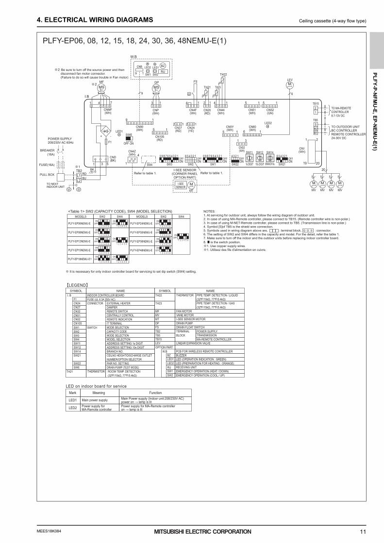
4. ELECTRICAL WIRING DIAGRAMS Ceiling cassette (4-way flow type)
PLFY-EP06, 08, 12, 15, 18, 24, 30, 36, 48NEMU-E(1)
0000005093.BOOK 11 ページ 2019年1月25日 金曜日 午後3時57分

MEES18K084
PL
FY
-P-N
FM
U-E
, E
P-N
EM
U-E
(1)
12
5. SOUND LEVELS Ceiling cassette (4-way flow type)
5. SOUND LEVELS5-1. Sound levels
5-2. NC curves
Operating sound levels(Low-Mid-High)
PLFY-P05NFMU-EPLFY-P08NFMU-EPLFY-P12NFMU-EPLFY-P15NFMU-EPLFY-P18NFMU-E
Sound level (A weighted)ModelUnit: dB(A)
Ceiling cassette series
UNIT
MICROPHONE
CEILING
Measurement location
(1.5m)4-7/8ft
26-28-3026-30-3326-30-3428-33-3933-39-43
(Low-Mid2-Mid1-High)
PLFY-EP06NEMU-EPLFY-EP08NEMU-EPLFY-EP12NEMU-EPLFY-EP15NEMU-EPLFY-EP18NEMU-E1PLFY-EP24NEMU-EPLFY-EP30NEMU-EPLFY-EP36NEMU-EPLFY-EP48NEMU-E
Sound level (A weighted)ModelUnit: dB(A)
19-23-25-2727-29-30-3127-29-30-3128-29-30-3128-30-32-3428-30-32-3428-31-33-3535-37-39-4136-39-42-45
50
Power Source: 208-230V 60HzExternal Static Pressure: 0Pa [0.00in.WG]PLFY-P05NFMU-E
60Hz
60HzLow60HzMiddle
High
Octave band center frequencies (Hz)
20-NC
30-NC
40-NC
continuous noiseaudible limit onApproximate minimum
Oct
ave
band
pre
ssur
e le
vel (
dB) 0
dB=2
0μPa
-NC
60-NC
8k4k2k1k50025012563
70.0
65.0
60.0
55.0
50.0
45.0
40.0
35.0
30.0
25.0
20.0
15.0
10.0
5.0
50
Power Source: 208-230V 60HzExternal Static Pressure: 0Pa [0.00in.WG]PLFY-P08NFMU-E
60Hz
60HzLow60HzMiddle
High
Octave band center frequencies (Hz)
20-NC
30-NC
40-NC
continuous noiseaudible limit onApproximate minimum
Oct
ave
band
pre
ssur
e le
vel (
dB) 0
dB=2
0μPa
-NC
60-NC
8k4k2k1k50025012563
70.0
65.0
60.0
55.0
50.0
45.0
40.0
35.0
30.0
25.0
20.0
15.0
10.0
5.0
50
Power Source: 208-230V 60HzExternal Static Pressure: 0Pa [0.00in.WG]PLFY-P12NFMU-E
60Hz
60HzLow60HzMiddle
High
Octave band center frequencies (Hz)
20-NC
30-NC
40-NC
continuous noiseaudible limit onApproximate minimum
Oct
ave
band
pre
ssur
e le
vel (
dB) 0
dB=2
0μPa
-NC
60-NC
8k4k2k1k50025012563
70.0
65.0
60.0
55.0
50.0
45.0
40.0
35.0
30.0
25.0
20.0
15.0
10.0
5.0
50
Power Source: 208-230V 60HzExternal Static Pressure: 0Pa [0.00in.WG]PLFY-P15NFMU-E
60Hz
60HzLow60HzMiddle
High
Octave band center frequencies (Hz)
20-NC
30-NC
40-NC
continuous noiseaudible limit onApproximate minimum
Oct
ave
band
pre
ssur
e le
vel (
dB) 0
dB=2
0μPa
-NC
60-NC
8k4k2k1k50025012563
70.0
65.0
60.0
55.0
50.0
45.0
40.0
35.0
30.0
25.0
20.0
15.0
10.0
5.0
50
Power Source: 208-230V 60HzExternal Static Pressure: 0Pa [0.00in.WG]PLFY-P18NFMU-E
60Hz
60HzLow60HzMiddle
High
Octave band center frequencies (Hz)
20-NC
30-NC
40-NC
continuous noiseaudible limit onApproximate minimum
Oct
ave
band
pre
ssur
e le
vel (
dB) 0
dB=2
0μPa
-NC
60-NC
8k4k2k1k50025012563
70.0
65.0
60.0
55.0
50.0
45.0
40.0
35.0
30.0
25.0
20.0
15.0
10.0
5.0
0000005093.BOOK 12 ページ 2019年1月25日 金曜日 午後3時57分

MEES18K084
PL
FY
-P-N
FM
U-E
, EP
-NE
MU
-E(1
)
13
5. SOUND LEVELS Ceiling cassette (4-way flow type)
50
Power Source: 280-230V 60HzExternal Static Pressure: 0Pa [0.00in.WG]PLFY-EP06NEMU-E
60Hz
60HzLow60HzMiddle260HzMiddle
High
Octave band center frequencies (Hz)
20-NC
30-NC
40-NC
continuous noiseaudible limit onApproximate minimum
Oct
ave
band
pre
ssur
e le
vel (
dB) 0
dB=2
0μPa
-NC
60-NC
8k4k2k1k50025012563
70.0
65.0
60.0
55.0
50.0
45.0
40.0
35.0
30.0
25.0
20.0
15.0
10.0
5.0 10.0
15.0
20.0
25.0
30.0
35.0
40.0
45.0
50.0
55.0
60.0
65.0
70.0
NC-60
NC-50
Oct
ave
band
pre
ssur
e le
vel (
dB) 0
dB=2
0μP
a
Approximate minimumaudible limit oncontinuous noise
NC-40
NC-30
NC-20
HighMiddle 60HzMiddle2 60HzLow 60Hz
60Hz
63 125 250 500 1k 2k 4k 8kOctave band center frequencies (Hz)
PLFY-EP08,12NEMU-EExternal Static Pressure: 0Pa [0.00in.WG]Power Source: 208-230V 60Hz
10.0
15.0
20.0
25.0
30.0
35.0
40.0
45.0
50.0
55.0
60.0
65.0
70.0
NC-60
NC-50
Oct
ave
band
pre
ssur
e le
vel (
dB) 0
dB=2
0μP
a
Approximate minimumaudible limit oncontinuous noise
NC-40
NC-30
NC-20
HighMiddle 60HzMiddle2 60HzLow 60Hz
60Hz
63 125 250 500 1k 2k 4k 8kOctave band center frequencies (Hz)
PLFY-EP15NEMU-EExternal Static Pressure: 0Pa [0.00in.WG]Power Source: 208-230V 60Hz
10.0
15.0
20.0
25.0
30.0
35.0
40.0
45.0
50.0
55.0
60.0
65.0
70.0
NC-60
NC-50
Oct
ave
band
pre
ssur
e le
vel (
dB) 0
dB=2
0μP
a
Approximate minimumaudible limit oncontinuous noise
NC-40
NC-30
NC-20
HighMiddle 60HzMiddle2 60HzLow 60Hz
60Hz
63 125 250 500 1k 2k 4k 8kOctave band center frequencies (Hz)
PLFY-EP18NEMU-E1, EP24NEMU-EExternal Static Pressure: 0Pa [0.00in.WG]Power Source: 208-230V 60Hz
10.0
15.0
20.0
25.0
30.0
35.0
40.0
45.0
50.0
55.0
60.0
65.0
70.0
NC-60
NC-50
Oct
ave
band
pre
ssur
e le
vel (
dB) 0
dB=2
0μP
a
Approximate minimumaudible limit oncontinuous noise
NC-40
NC-30
NC-20
HighMiddle 60HzMiddle2 60HzLow 60Hz
60Hz
63 125 250 500 1k 2k 4k 8kOctave band center frequencies (Hz)
PLFY-EP30NEMU-EExternal Static Pressure: 0Pa [0.00in.WG]Power Source: 208-230V 60Hz
10.0
15.0
20.0
25.0
30.0
35.0
40.0
45.0
50.0
55.0
60.0
65.0
70.0
NC-60
NC-50
Oct
ave
band
pre
ssur
e le
vel (
dB) 0
dB=2
0μP
a
Approximate minimumaudible limit oncontinuous noise
NC-40
NC-30
NC-20
HighMiddle 60HzMiddle2 60HzLow 60Hz
60Hz
63 125 250 500 1k 2k 4k 8kOctave band center frequencies (Hz)
PLFY-EP36NEMU-EExternal Static Pressure: 0Pa [0.00in.WG]Power Source: 208-230V 60Hz
10.0
15.0
20.0
25.0
30.0
35.0
40.0
45.0
50.0
55.0
60.0
65.0
70.0
NC-60
NC-50
Oct
ave
band
pre
ssur
e le
vel (
dB) 0
dB=2
0μP
a
Approximate minimumaudible limit oncontinuous noise
NC-40
NC-30
NC-20
HighMiddle 60HzMiddle2 60HzLow 60Hz
60Hz
63 125 250 500 1k 2k 4k 8kOctave band center frequencies (Hz)
PLFY-EP48NEMU-EExternal Static Pressure: 0Pa [0.00in.WG]Power Source: 208-230V 60Hz
0000005093.BOOK 13 ページ 2019年1月25日 金曜日 午後3時57分

MEES18K084
PL
FY
-P-N
FM
U-E
, E
P-N
EM
U-E
(1)
14
6. TEMPERATURE/AIRFLOW DISTRIBUTIONS Ceiling cassette (4-way flow type)
6. TEMPERATURE/AIRFLOW DISTRIBUTIONS6-1. Temperature distributions
PLFY-P05-18NFMU-E
Note : These figures show typical temperature distributions in the conditions above. In the actual installation, they may differ from these figures under the influence of air temperature conditions, ceiling height, cooling/heating load,obstacles,etc.
<Cooling mode>HorizontalCeiling height : 2.7m (8.9ft)
<Heating mode>DownwardCeiling height : 2.7m (8.9ft)
01234(13.1) (13.1)(9.9) (9.9)(6.6) (6.6)(3.3) (3.3)
(13.1) (13.1)(9.9) (9.9)(6.6) (6.6)(3.3) (3.3)
0
1
2
2.7(8.9)
(6.6)
(3.3)
(8.9)
(6.6)
(3.3)
Floor distance <m(ft)>
Hei
ght
<m(ft
)>
21(70)
2523 21
2523
4321
Hei
ght
<m(ft
)>
1
2
2.735
(95)
27
31
35
27
31
Floor distance <m(ft)>
012340
123
19(66)
1 2 3 4
2319
(73) (73)(77) (77)
(70)
(88) (88)
(81) (81)
(73) (73)
(66)
(95)
< > ̊C °F( )
< > ̊C °F( )
0000005093.BOOK 14 ページ 2019年1月25日 金曜日 午後3時57分

MEES18K084
PL
FY
-P-N
FM
U-E
, EP
-NE
MU
-E(1
)
15
6. TEMPERATURE/AIRFLOW DISTRIBUTIONS Ceiling cassette (4-way flow type)
Note : These figures show typical temperature distributions in the conditions above. In the actual installation, they may differ from these figures under the influence of air temperature conditions, ceiling height, cooling/heating load,obstacles,etc.
PLFY-EP06NEMU-E<Cooling mode>StandardFlow angle: 30° 4-way flowceiling height: 2.7m(8.9ft)
<Heating mode> StandardFlow angle: 60° 4-way flowceiling height: 2.7m(8.9ft)
PLFY-EP08, 12NEMU-E<Cooling mode>StandardFlow angle: 30° 4-way flowceiling height: 2.7m(8.9ft)
<Heating mode> StandardFlow angle: 60° 4-way flowceiling height: 2.7m(8.9ft)
PLFY-EP15NEMU-E<Cooling mode>StandardFlow angle: 30° 4-way flowceiling height: 2.7m(8.9ft)
<Heating mode>StandardFlow angle: 60° 4-way flowceiling height: 2.7m(8.9ft)
Hei
ght<
m(ft
)>
Floor distance<m(ft)>
Hei
ght<
m(ft
)>
Floor distance<m(ft)>
1.0(3.3)
02.5
(8.2)2
(6.6)1
(3.3)1
(3.3)0 2
(6.6)2.5
(8.2)
2.0(6.6)
2.7(8.9)
23(73)
23(73)
Hei
ght<
m(ft
)>
Floor distance<m(ft)>
<˚C(°F)>
<˚C(°F)>
27(81)
27(81)
27(81)
27(81)
25(77)
25(77)
1.0(3.3)
02.5
(8.2)2
(6.6)1
(3.3)1
(3.3)0 2
(6.6)2.5
(8.2)
2.0(6.6)
2.7(8.9)
Hei
ght<
m(ft
)>
Floor distance<m(ft)>
<˚C(°F)>
<˚C(°F)>
28(82)
24(75)
26(79)
24(75)
30(86)30
(86)30
(86)
28(82)
24(75)
26(79)
24(75)
30(86)30
(86)30
(86)
Hei
ght<
m(ft
)>
Floor distance<m(ft)>
<˚C(°F)>
1.0(3.3)
03
(9.9)2
(6.6)1
(3.3)0 1
(3.3)2
(6.6)3
(9.9)
2.0(6.6)
2.7(8.9)
27(81)
27(81)
27(81)
27(81)
23(73)23
(73)23
(73)23
(73)23
(73)23
(73)
25(77)
25(77)
Hei
ght<
m(ft
)>
Floor distance<m(ft)>
<˚C(°F)>
1.0(3.3)
03
(9.9)2
(6.6)1
(3.3)0 1
(3.3)2
(6.6)3
(9.9)
2.0(6.6)
2.7(8.9)
28(82)
28(82)26(79) 26(79)
24(75)
24(75)
24(75)
24(75)30
(86)30
(86)30
(86)30
(86)30
(86)30
(86)
0
0
2.7(8.9)
2.0(6.6)
1.0(3.3)
2.5(8.2)
2(6.6)
1(3.3)
2.5(8.2)
2(6.6)
1(3.3)
0
0
2.7(8.9)
2.0(6.6)
1.0(3.3)
2.5(8.2)
2(6.6)
1(3.3)
2.5(8.2)
2(6.6)
1(3.3)
27(81)27
(81)27
(81)25(77)25
(77)25
(77)25
(77)25
(77)25
(77)
23(73)23
(73)23
(73)23
(73)23
(73)23
(73)
27(81)27
(81)27
(81)
27(81)27
(81)27
(81)
24(75)24
(75)24
(75)
24(75)24
(75)24
(75)
24(75)24
(75)24
(75)
26(79)26
(79)26
(79)
28(82)28
(82)28
(82)28
(82)28
(82)28
(82)
26(79)26
(79)26
(79)
0000005093.BOOK 15 ページ 2019年1月25日 金曜日 午後3時57分

MEES18K084
PL
FY
-P-N
FM
U-E
, E
P-N
EM
U-E
(1)
16
6. TEMPERATURE/AIRFLOW DISTRIBUTIONS Ceiling cassette (4-way flow type)
Note : These figures show typical temperature distributions in the conditions above. In the actual installation, they may differ from these figures under the influence of air temperature conditions, ceiling height, cooling/heating load,obstacles,etc.
PLFY-EP18NEMU-E1, EP24, 30NEMU-E<Cooling mode>StandardFlow angle: 30° 4-way flowceiling height: 2.7m(8.9ft)
<Heating mode>StandardFlow angle: 60° 4-way flowceiling height: 2.7m(8.9ft)
PLFY-EP36NEMU-E<Cooling mode>StandardFlow angle: 30° 4-way flowceiling height: 3.2m(10.5ft)
<Heating mode>StandardFlow angle: 60° 4-way flowceiling height: 3.2m(10.5ft)
PLFY-EP48NEMU-E<Cooling mode>StandardFlow angle: 30° 4-way flowceiling height: 3.2m(10.5ft)
<Heating mode>StandardFlow angle: 60° 4-way flowceiling height: 3.2m(10.5ft)
Hei
ght<
m(ft
)>
Floor distance<m(ft)>
<˚C(°F)>
1.0(3.3)
0
2.0(6.6)
2.7(8.9)
4(13.1)
3(9.9)
4(13.1)
3(9.9)
2(6.6)
2(6.6)
1(3.3)
1(3.3)
0
Floor distance<m(ft)>
4(13.1)
3(9.9)
4(13.1)
3(9.9)
2(6.6)
2(6.6)
1(3.3)
1(3.3)
0
Hei
ght<
m(ft
)>
<˚C(°F)>
1.0(3.3)
0
2.0(6.6)
2.7(8.9)
Hei
ght<
m(ft
)>
Floor distance<m(ft)>
<˚C(°F)>
1.0(3.3)
2.0(6.6)
3.0(9.9)
3.2(10.5)
5(16.4)
5(16.4)
3(9.9)
4(13.1)
4(13.1)
3(9.9)
2(6.6)
2(6.6)
1(3.3)
1(3.3)
0
27(81)
27(81)
27(81)
27(81)
25(77)
25(77)
23(73)
23(73)
0
Hei
ght<
m(ft
)>
Floor distance<m(ft)>
<˚C(°F)>
1.0(3.3)
2.0(6.6)
3.0(9.9)
3.2(10.5)
5(16.4)
5(16.4)
3(9.9)
4(13.1)
4(13.1)
3(9.9)
2(6.6)
2(6.6)
1(3.3)
1(3.3)
00
26(79)
26(79)
26(79)26
(79)26
(79)26
(79)24
(75)24
(75)24
(75)24
(75)
28(82)
28(82)
28(82)
28(82)
30(86)
30(86)
30(86)30
(86)30
(86)30
(86)
Hei
ght<
m(ft
)>
Floor distance<m(ft)>
<˚C(°F)>
1.0(3.3)
0
2.0(6.6)
3.0(9.9)
3.2(10.5)
5(16.4)
5(16.4)
5.5(18.0)
5.5(18.0)
3(9.9)
3(9.9)
4(13.1)
4(13.1)
2(6.6)
2(6.6)
1(3.3)
1(3.3)
0
23(73)
23(73)
23(73)23
(73)23
(73)23
(73)
27(81)
27(81) 26
(79)26
(79)26
(79)26
(79)
24(75)
24(75)
24(75)
24(75)
Hei
ght<
m(ft
)>
Floor distance<m(ft)>
<˚C(°F)>
1.0(3.3)
0
2.0(6.6)
3.0(9.9)
3.2(10.5)
5(16.4)
5(16.4)
5.5(18.0)
5.5(18.0)
3(9.9)
3(9.9)
4(13.1)
4(13.1)
2(6.6)
2(6.6)
1(3.3)
1(3.3)
0
32(90)32
(90)32
(90)32
(90)32
(90)32
(90)30
(86)30
(86)30
(86)30
(86)30
(86)30
(86)28
(82)28
(82)28
(82)28
(82)28
(82)28
(82)28
(82)28
(82)
30(86)30
(86)
32(90)32
(90)
25(77)
25(77)
25(77)
25(77)
25(77)
25(77)
23(73)23
(73)23
(73)23
(73)23
(73)23
(73)
27(81)27
(81)27
(81)27
(81)
24(75)
24(75)
26(79)
26(79)
24(75)
24(75)
28(82)
28(82)
30(86)
30(86)
0000005093.BOOK 16 ページ 2019年1月25日 金曜日 午後3時57分

MEES18K084
PL
FY
-P-N
FM
U-E
, EP
-NE
MU
-E(1
)
17
6. TEMPERATURE/AIRFLOW DISTRIBUTIONS Ceiling cassette (4-way flow type)
6-2. Airflow distributions
Note : These figures show typical airflow distributions in the conditions above. In the actual installation, they may differ from these figures under the influence of air temperature conditions, ceiling height, cooling/heating load,obstacles,etc.
PLFY-P05-18NFMU-E
012340
1
2
2.7<m/s(ft/s)>
0.5(1.6) 1.0(3.3) 2.0(6.6) 0.5(1.6)1.0(3.3)2.0(6.6)
1 2 3 4
1
2
2.7
1.0
2.0(6.6) (6.6)
(3.3) (3.3)
(1.6) (1.6)
1.0
2.0
<m/s(ft/s)>
012340
1
0.5
1 2 3 4
0.5
<Cooling mode>HorizontalCeiling height : 2.7m (8.9ft)
<Heating mode>DownwardCeiling height : 2.7m (8.9ft)
Hei
ght
<m(ft
)>H
eigh
t<m
(ft)>
(8.9)
(6.6)
(3.3)
(8.9)
(6.6)
(3.3)
Floor distance <m(ft)>
Floor distance <m(ft)>
(13.1) (13.1)(9.9) (9.9)(6.6) (6.6)(3.3) (3.3)
(13.1) (13.1)(9.9) (9.9)(6.6) (6.6)(3.3) (3.3)
0000005093.BOOK 17 ページ 2019年1月25日 金曜日 午後3時57分

MEES18K084
PL
FY
-P-N
FM
U-E
, E
P-N
EM
U-E
(1)
18
6. TEMPERATURE/AIRFLOW DISTRIBUTIONS Ceiling cassette (4-way flow type)
Note : These figures show typical airflow distributions in the conditions above. In the actual installation, they may differ from these figures under the influence of air temperature conditions, ceiling height, cooling/heating load,obstacles,etc.
PLFY-EP06NEMU-E<Cooling mode>Flow angle: 30°
<Heating mode>Flow angle: 60°
PLFY-EP08, 12NEMU-E<Cooling mode>Flow angle: 30°
<Heating mode>Flow angle: 60°
PLFY-EP15NEMU-E<Cooling mode>Flow angle: 30°
<Heating mode>Flow angle: 60°
1.0(3.3)
02.5
(8.2)2
(6.6)1
(3.3)1
(3.3)0 2
(6.6)2.5
(8.2)
2.0(6.6)
2.7(8.9)
Hei
ght<
m(ft
)>
Floor distance<m(ft)>
<m/s(ft/s)>
1.0(3.3)
1.0(3.3)
0.5(1.6)
0.5(1.6)
0.5(1.6)
0.5(1.6)
2.0(6.6)
2.0(6.6)1.5
(4.9)1.5
(4.9)
2.0(6.6)2.0
(6.6)2.0
(6.6)2.0
(6.6)1.5(4.9)1.5
(4.9)1.5
(4.9)1.5
(4.9)
1.0(3.3)
02.5
(8.2)2
(6.6)1
(3.3)1
(3.3)0 2
(6.6)2.5
(8.2)
2.0(6.6)
2.7(8.9)
Hei
ght<
m(ft
)>
Floor distance<m(ft)>
<m/s(ft/s)>2.0
(6.6)2.0
(6.6)
1.0(3.3)
1.0(3.3)
0.5(1.6)
0.5(1.6)
1.5(4.9)1.5
(4.9)1.5
(4.9)1.5
(4.9)
Hei
ght<
m(ft
)>
Floor distance<m(ft)>
<m/s(ft/s)>
1.0(3.3)
03
(9.9)2
(6.6)1
(3.3)0 1
(3.3)2
(6.6)3
(9.9)
2.0(6.6)
2.7(8.9)
1.0(3.3)
1.0(3.3)
0.5(1.6)
0.5(1.6)
1.5(4.9)
1.5(4.9)
2.0(6.6)
2.0(6.6)
2.0(6.6)2.0
(6.6)2.0
(6.6)2.0
(6.6)0.5(1.6)
0.5(1.6)
0.5(1.6)0.5
(1.6)0.5
(1.6)0.5
(1.6)
Hei
ght<
m(ft
)>
Floor distance<m(ft)>
<m/s(ft/s)>
1.0(3.3)
03
(9.9)2
(6.6)1
(3.3)0 1
(3.3)2
(6.6)3
(9.9)
2.0(6.6)
2.7(8.9)
1.0(3.3)
1.0(3.3)
0.5(1.6)
0.5(1.6)
1.5(4.9)
1.5(4.9)
2.0(6.6)
2.0(6.6)
1.5(4.9)1.5
(4.9)1.5
(4.9)1.5
(4.9)
2.0(6.6)2.0
(6.6)2.0
(6.6)2.0
(6.6)
Hei
ght<
m(ft
)>
Floor distance<m(ft)>
<m/s(ft/s)>
Hei
ght<
m(ft
)>
Floor distance<m(ft)>
<m/s(ft/s)>
0
0
2.7(8.9)
2.0(6.6)
1.0(3.3)
2.5(8.2)
2(6.6)
1(3.3)
2.5(8.2)
2(6.6)
1(3.3)
0
0
2.7(8.9)
2.0(6.6)
1.0(3.3)
2.5(8.2)
2(6.6)
1(3.3)
2.5(8.2)
2(6.6)
1(3.3)
2.0(6.6)2.0
(6.6)2.0
(6.6)
1.5(4.9)1.5
(4.9)1.5
(4.9)1.5
(4.9)1.5
(4.9)1.5
(4.9)
0.5(1.6)0.5
(1.6)0.5
(1.6)
0.5(1.6)0.5
(1.6)0.5
(1.6)0.5
(1.6)0.5
(1.6)0.5
(1.6)
1.0(3.3)1.0
(3.3)1.0
(3.3)1.0
(3.3)1.0
(3.3)1.0
(3.3)
1.0(3.3)1.0
(3.3)1.0
(3.3)1.0
(3.3)1.0
(3.3)1.0
(3.3)
0.5(1.6)0.5
(1.6)0.5
(1.6)
0.5(1.6)0.5
(1.6)0.5
(1.6)
0.5(1.6)0.5
(1.6)0.5
(1.6)
2.0(6.6)2.0
(6.6)2.0
(6.6)
0000005093.BOOK 18 ページ 2019年1月25日 金曜日 午後3時57分

MEES18K084
PL
FY
-P-N
FM
U-E
, EP
-NE
MU
-E(1
)
19
6. TEMPERATURE/AIRFLOW DISTRIBUTIONS Ceiling cassette (4-way flow type)
Hei
ght<
m(ft
)>
Floor distance<m(ft)>
<m/s(ft/s)>
1.0(3.3)
0
2.0(6.6)
2.7(8.9)
4(13.1)
3(9.9)
4(13.1)
3(9.9)
2(6.6)
2(6.6)
1(3.3)
1(3.3)
0
1.0(3.3)
1.0(3.3)
1.5(4.9)
1.5(4.9)
2.5(8.2)2.5
(8.2)2.5
(8.2)2.5
(8.2)2.5
(8.2)2.5
(8.2)
3.0(9.9)
3.0(9.9)
3.5(11.5)
3.5(11.5)
2.0(6.6)
2.0(6.6)
0.5(1.6)
0.5(1.6)
Floor distance<m(ft)>
4(13.1)
3(9.9)
4(13.1)
3(9.9)
2(6.6)
2(6.6)
1(3.3)
1(3.3)
0
Hei
ght<
m(ft
)>
<m/s(ft/s)>
1.0(3.3)
0
2.0(6.6)
2.7(8.9)
1.5(4.9)
1.5(4.9)
0.5(1.6)
0.5(1.6)
1.0(3.3)
1.0(3.3)
2.5(8.2)
2.5(8.2)
3.0(9.9)
3.0(9.9)
2.0(6.6)2.0
(6.6)2.0
(6.6)2.0
(6.6)2.0
(6.6)2.0
(6.6)2.0
(6.6)2.0
(6.6)
Hei
ght<
m(ft
)>
Floor distance<m(ft)>
<m/s(ft/s)>
1.0(3.3)
2.0(6.6)
3.0(9.9)
3.2(10.5)
5(16.4)
5(16.4)
3(9.9)
4(13.1)
4(13.1)
3(9.9)
2(6.6)
2(6.6)
1(3.3)
1(3.3)
00
2.0(6.6)
2.0(6.6)
1.5(4.9)
1.5(4.9)
1.0(3.3)
1.0(3.3)0.5
(1.6)0.5(1.6)
2.5(8.2)2.5
(8.2)2.5
(8.2)2.5
(8.2)2.5
(8.2)2.5
(8.2)
3.0(9.9)
3.0(9.9)
Hei
ght<
m(ft
)>
Floor distance<m(ft)>
<m/s(ft/s)>
1.0(3.3)
2.0(6.6)
3.0(9.9)
3.2(10.5)
5(16.4)
5(16.4)
3(9.9)
4(13.1)
4(13.1)
3(9.9)
2(6.6)
2(6.6)
1(3.3)
1(3.3)
00
2.0(6.6)
2.0(6.6)
1.0(3.3)
1.0(3.3)
0.5(1.6)
0.5(1.6)
0.5(1.6)
0.5(1.6)
2.5(8.2)2.5
(8.2)2.5
(8.2)2.5
(8.2)2.5
(8.2)2.5
(8.2)2.5
(8.2)2.5
(8.2)2.5
(8.2)2.5
(8.2)2.5
(8.2)2.5
(8.2)
3.0(9.9)
3.0(9.9)
1.5(4.9)1.5
(4.9)1.5
(4.9)1.5
(4.9)1.5
(4.9)1.5
(4.9)1.5
(4.9)1.5
(4.9)
Hei
ght<
m(ft
)>
Floor distance<m(ft)>
<m/s(ft/s)>
1.0(3.3)
0
2.0(6.6)
3.0(9.9)
3.2(10.5)
5(16.4)
5(16.4)
5.5(18.0)
5.5(18.0)
3(9.9)
3(9.9)
4(13.1)
4(13.1)
2(6.6)
2(6.6)
1(3.3)
1(3.3)
0
2.0(6.6)
1.0(3.3)
2.0(6.6)
1.0(3.3)
2.0(6.6)2.0
(6.6)
1.0(3.3)1.0
(3.3)
0.5(1.6)
3.0(9.9)
4.0(13.1)
4.0(13.1)
4.0(13.1)
4.0(13.1)
4.0(13.1)
4.0(13.1)
2.0(6.6)2.0
(6.6)
1.0(3.3)1.0
(3.3)
0.5(1.6)
3.0(9.9)
4.0(13.1)
4.0(13.1)
Hei
ght<
m(ft
)>
Floor distance<m(ft)>
<m/s(ft/s)>
1.0(3.3)
0
2.0(6.6)
3.0(9.9)
3.2(10.5)
5(16.4)
5(16.4)
5.5(18.0)
5.5(18.0)
3(9.9)
3(9.9)
4(13.1)
4(13.1)
2(6.6)
2(6.6)
1(3.3)
1(3.3)
0
2.0(6.6)
1.5(4.9)
4.0(13.1)
2.0(6.6)2.0
(6.6)1.5
(4.9)1.5
(4.9)
4.0(13.1)
4.0(13.1)
2.0(6.6)
1.5(4.9)
2.0(6.6)2.0
(6.6)
1.0(3.3)
1.0(3.3)
1.0(3.3)1.0
(3.3)1.0
(3.3)1.0
(3.3)
1.5(4.9)1.5
(4.9)
0.5(1.6)
0.5(1.6)
0.5(1.6)0.5
(1.6)0.5
(1.6)0.5
(1.6)0.5(1.6)
0.5(1.6)
3.0(9.9)
3.0(9.9)3.0
(9.9)
4.0(13.1)
4.0(13.1)
4.0(13.1)
Note : These figures show typical airflow distributions in the conditions above. In the actual installation, they may differ from these figures under the influence of air temperature conditions, ceiling height, cooling/heating load,obstacles,etc.
PLFY-EP18NEMU-E1, EP24, 30NEMU-E<Cooling mode>Flow angle: 30°
<Heating mode>Flow angle: 60°
PLFY-EP36NEMU-E<Cooling mode>Flow angle: 30°
<Heating mode>Flow angle: 60°
PLFY-EP48NEMU-E<Cooling mode>Flow angle: 30°
<Heating mode>Flow angle: 60°
0000005093.BOOK 19 ページ 2019年1月25日 金曜日 午後3時57分

MEES18K084
PL
FY
-P-N
FM
U-E
, E
P-N
EM
U-E
(1)
20
7. OUTDOOR AIR INTAKE AMOUNT & STATIC PRESSURE Ceiling cassette (4-way flow type)
7. OUTDOOR AIR INTAKE AMOUNT & STATIC PRESSURE
PLFY-P05, 08, 12, 15, 18NFMU-E
120°
120°ø 3-15/16
5-1/2
7-5/
16
8-3/
16
Detail drawing of fresh air intake
At the time of installation, use the duct holes (cut out) located at the positions shown in following diagram, as and when required.
Ceiling surface
Refrigerant pipe Drain pipeElectrical Box
Fresh air intake
Cut out holeBurring hole
1-15
/32
+3/1
6 0
Stat
ic p
ress
ure
[Pa(
in.W
.G.×
10-2
)]
0 0.3 0.6 0.9 1.2 1.5
10 0 20 30 40 50 [CFM]
Airflow rate
[CMM]−150(-60)
−120(-48)
−90(-36)
−60(-24)
−30(-12)
0
Taking air into the unit
NOTE: Fresh air intake amount should be 10% or less of whole air amount to prevent dew dripping.
Q
0
BA C
1 Curve in theleft graphs
Duct characteristicsat site
QA
EC
2
QQa
AD
3
Q…Designed amount of fresh air intake <CMM (CFM)>
A…Static pressure loss of fresh air intake duct system with air flow amount Q <Pa (in.W.G.o10-2)>
B…Forced static pressure at air condi-tioner inlet with air flow amount Q
<Pa (in.W.G.o10-2)>C…Static pressure of booster fan with
air flow amount Q <Pa (in.W.G.o10-
2)>D…Static pressure loss increase amount
of fresh air intake duct system for air flow amount Q <Pa (in.W.G.o10-2)>
E…Static pressure of indoor unit with air flow amount Q <Pa (in.W.G.o10-2)>
Qa…Estimated amount of fresh air intake without D <CMM (CFM)>
How to read curves
PLFY-EP06, 08, 12, 15, 18, 24, 30, 36, 48NEMU-E(1)At the time of installation, use the duct holes (cut out) located at the positions shown in following diagram, as and when required.• A fresh air intake hole for the optional multi function casement can also be made.
Note:The figures marked with * in the drawing below represent the dimensions of the main unit excluding those of the optional multi function casement.When installing the optional multi function casement, add 5-5/16” (135 mm) to the dimensions marked on the figure.When installing the branch ducts, be sure to insulate adequately. Otherwise, condensation and dripping may occur. Unit : in (mm)
Branch duct hole
14-ø1/8 (ø2.8) burring hole
Indoor unit
ø5-29/32 (ø150) cut out hole
Fresh air intake hole
ø6-7/8 (ø175) burring hole pitch
Drain pipe
Fresh air intake hole diagram
Refrigerant pipe
3-ø1/8 (ø2.8) burring hole
Branch duct hole diagram (view from either side)
ø4-29/32 (ø125) burring hole pitch
ø3-15/16 (ø100) cut out hole
Ceiling
6-7/
32(*
158) 12
0
120
13-25/32 (350)
3-17/32(90)
3-15/16(100)
3-15/16(90)
3-17/32(90)
70
3-15
/16
(100
)
5-1/
8 (1
30)
*6-3
/32
(155
)
*6-9
/16
(167
)
A
AA
0000005093.BOOK 20 ページ 2019年1月25日 金曜日 午後3時57分
MEES18K084
PL
FY
-P-N
FM
U-E
, EP
-NE
MU
-E(1
)
21
7. OUTDOOR AIR INTAKE AMOUNT & STATIC PRESSURE Ceiling cassette (4-way flow type)
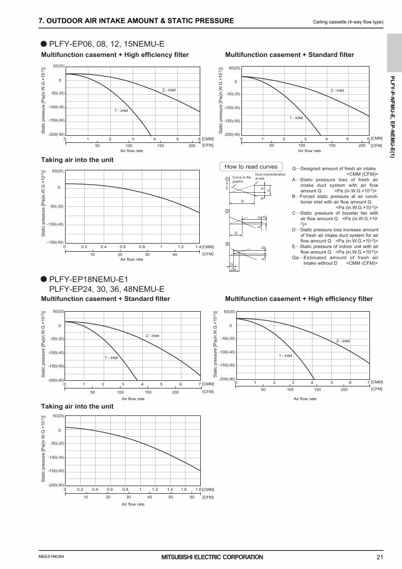
PLFY-EP06, 08, 12, 15NEMU-E
PLFY-EP24, 30, 36, 48NEMU-EPLFY-EP18NEMU-E1
2 - inlet
1 - inlet
2 - inlet
1 - inlet
2 - inlet
1 - inlet
2 - inlet
1 - inlet
Multifunction casement + High efficiency filter Multifunction casement + Standard filter
Multifunction casement + Standard filter
Taking air into the unit
Multifunction casement + High efficiency filter
Taking air into the unit
50 100 150 200 [CFM][CMM]
10 20 30 40 [CFM]
[CMM]
50 100 150 200 [CFM]
[CMM]
50 100 150 200 [CFM]
[CMM]
10 20 30 40 50 60 [CFM]
[CMM]
50 100 150 200 [CFM]
[CMM]
Q
0
BA C
1 Curve in thegraphs.
Duct characteristicsat site
Q
AE
C
2
QQa
AD
3
Q…Designed amount of fresh air intake <CMM (CFM)>
A…Static pressure loss of fresh air intake duct system with air flow amount Q <Pa (in.W.G.×10-2)>
B…Forced static pressure at air condi-tioner inlet with air flow amount Q
<Pa (in.W.G.×10-2)>C…Static pressure of booster fan with
air flow amount Q <Pa (in.W.G.×10-
2)>D…Static pressure loss increase amount
of fresh air intake duct system for air flow amount Q <Pa (in.W.G.×10-2)>
E…Static pressure of indoor unit with air flow amount Q <Pa (in.W.G.×10-2)>
Qa…Estimated amount of fresh air intake without D <CMM (CFM)>
How to read curves
0 1 2 3 4 5 6
-150(-60)
-200(-80)
-100(-40)
-50(-20)
0
50(20)
0 0.2 0.4 0.6 0.8 1 1.2 1.4-150(-60)
-100(-40)
-50(-20)
0
50(20)
0 1 2 3 4 5 6
-150(-60)
-200(-80)
-100(-40)
-50(-20)
0
50(20)
-150(-60)
-200(-80)
-100(-40)
-50(-20)
0
50(20)
0 1 2 3 4 5 6 7
-150(-60)
-200(-80)
-100(-40)
-50(-20)
0
50(20)
0 0.2 0.4 0.6 0.8 1 1.2 1.4 1.6 1.8
-150(-60)
-200(-80)
-100(-40)
-50(-20)
0
50(20)
0 1 2 3 4 5 76
Air flow rate Air flow rate
Stat
ic p
ress
ure
[Pa(
in.W
.G.×
10-2
)]
Stat
ic p
ress
ure
[Pa(
in.W
.G.×
10-2
)]
Air flow rate
Stat
ic p
ress
ure
[Pa(
in.W
.G.×
10-2
)]
Air flow rate
Stat
ic p
ress
ure
[Pa(
in.W
.G.×
10-2
)]
Air flow rate
Stat
ic p
ress
ure
[Pa(
in.W
.G.×
10-2
)]
Air flow rate
Stat
ic p
ress
ure
[Pa(
in.W
.G.×
10-2
)]
0000005093.BOOK 21 ページ 2019年1月25日 金曜日 午後3時57分
MEES18K084
PL
FY
-P-N
FM
U-E
, E
P-N
EM
U-E
(1)
22
8. ELECTRICAL CHARACTERISTICS Ceiling cassette (4-way flow type)
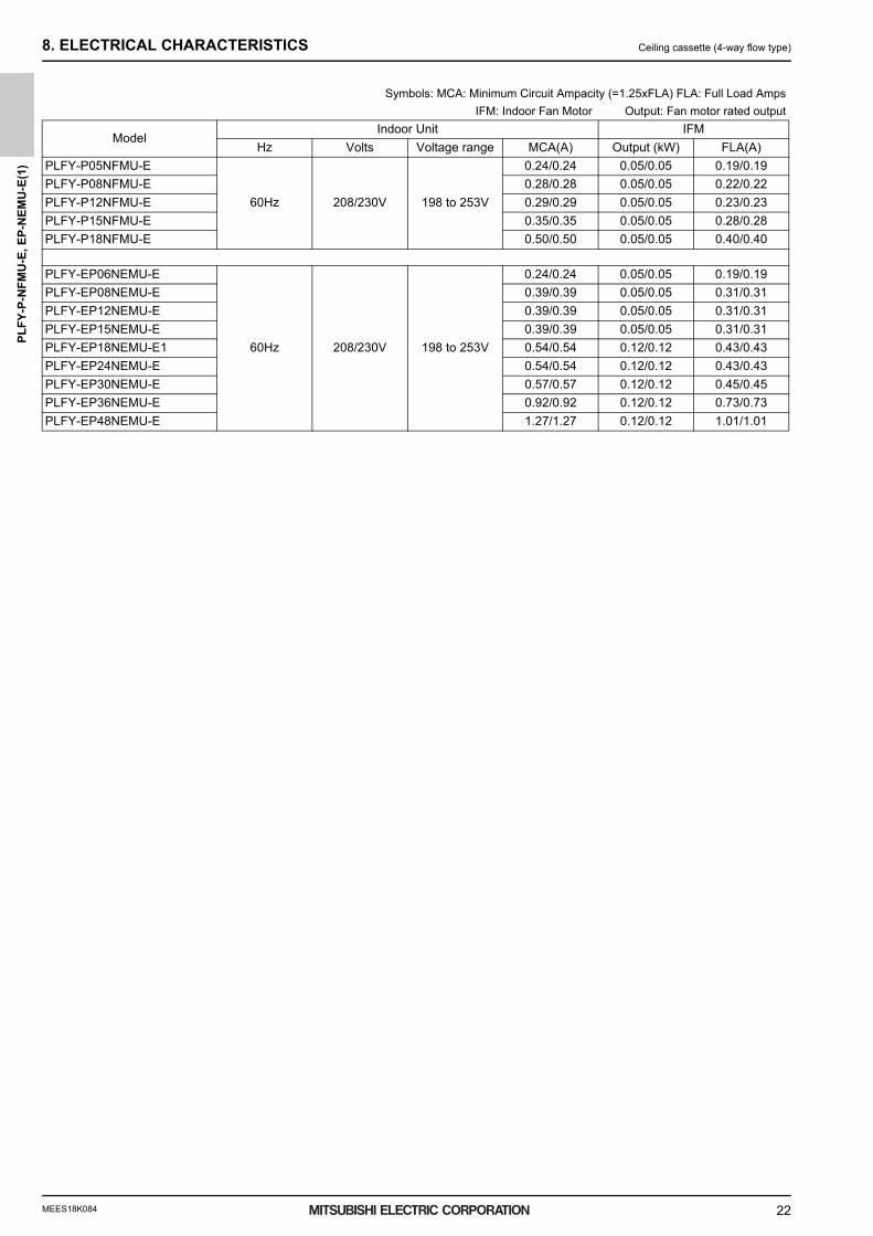
8. ELECTRICAL CHARACTERISTICS
Symbols: MCA: Minimum Circuit Ampacity (=1.25xFLA) FLA: Full Load Amps
IFM: Indoor Fan Motor Output: Fan motor rated output
ModelIndoor Unit IFM
Hz Volts Voltage range MCA(A) Output (kW) FLA(A)
PLFY-P05NFMU-E
60Hz 208/230V 198 to 253V
0.24/0.24 0.05/0.05 0.19/0.19
PLFY-P08NFMU-E 0.28/0.28 0.05/0.05 0.22/0.22
PLFY-P12NFMU-E 0.29/0.29 0.05/0.05 0.23/0.23
PLFY-P15NFMU-E 0.35/0.35 0.05/0.05 0.28/0.28
PLFY-P18NFMU-E 0.50/0.50 0.05/0.05 0.40/0.40
PLFY-EP06NEMU-E
60Hz 208/230V 198 to 253V
0.24/0.24 0.05/0.05 0.19/0.19
PLFY-EP08NEMU-E 0.39/0.39 0.05/0.05 0.31/0.31
PLFY-EP12NEMU-E 0.39/0.39 0.05/0.05 0.31/0.31
PLFY-EP15NEMU-E 0.39/0.39 0.05/0.05 0.31/0.31
PLFY-EP18NEMU-E1 0.54/0.54 0.12/0.12 0.43/0.43
PLFY-EP24NEMU-E 0.54/0.54 0.12/0.12 0.43/0.43
PLFY-EP30NEMU-E 0.57/0.57 0.12/0.12 0.45/0.45
PLFY-EP36NEMU-E 0.92/0.92 0.12/0.12 0.73/0.73
PLFY-EP48NEMU-E 1.27/1.27 0.12/0.12 1.01/1.01
0000005093.BOOK 22 ページ 2019年1月25日 金曜日 午後3時57分

MEES18K084
PL
FY
-P-N
FM
U-E
, EP
-NE
MU
-E(1
)
23
9. OPTIONAL PARTS Ceiling cassette (4-way flow type)
9. OPTIONAL PARTS9-1. Optional parts line up for the Indoor unit
9-2. Air outlet shutter plate
Description Model
PLFY-P-NFMU-EPLFY-EP-NEMU-E(1)
Multi-function casementPAC-SJ41TM-E
Air outlet shutter platePAC-SJ37SP-E
High efficiency filter element PAC-SH59KF-E PAC-SJ41TM-E is necessary to use with filter PAC-SH59KF-E.
Air outlet shutter plateMulti-function casementHigh efficiency filter element3D i-see Sensor corner panel3D i-see Sensor panelWireless signal receiverExternal heater adapterDuct flange for fresh air intake
PAC-SJ37SP-E (for EP-NEMU)PAC-SJ41TM-E (for EP-NEMU)PAC-SH59KF-E (for EP-NEMU)PAC-SF1ME-E (for P-NFMU)SLP-18FAEU (for P-NFMU)/PLP-40EAEU (for EP-NEMU)PAR-SF9FA-E (for P-NFMU)/PAR-SR3LA-E (for EP-NEMU)PAC-YU25HT (for EP-NEMU)PAC-SH65OF-E (for EP-NEMU)
Using the air outlet shutter plate to block the air outlet to modify the air-way from 4 to 3 or 2.With one shutter plate, 4 air-ways can be changed to 3;With two shutter plates, 4 air-ways can be changed to 2;Changing to 1 way is not allowed. Material: Foamed polyethylene + foamed urethane, color: Black
Item Shutter plate
Quantity 2
Shape
Shutter plate
1
Detailed installation information should be referred to its Installation Manual.
0000005093.BOOK 23 ページ 2019年1月25日 金曜日 午後3時57分
MEES18K084
PL
FY
-P-N
FM
U-E
, E
P-N
EM
U-E
(1)
24
9. OPTIONAL PARTS Ceiling cassette (4-way flow type)
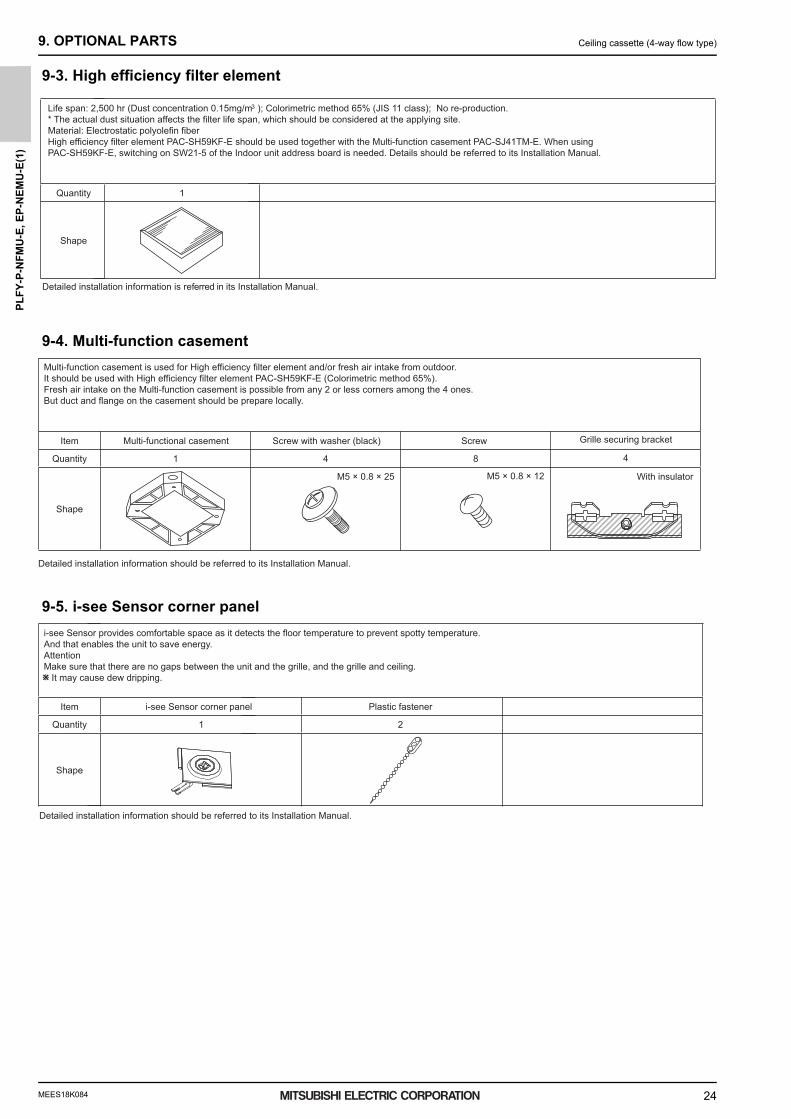
9-3. High efficiency filter element
9-4. Multi-function casement
9-5. i-see Sensor corner panel
Life span: 2,500 hr (Dust concentration 0.15mg/m ); Colorimetric method 65% (JIS 11 class); No re-production.3
* The actual dust situation affects the filter life span, which should be considered at the applying site.Material: Electrostatic polyolefin fiberHigh efficiency filter element PAC-SH59KF-E should be used together with the Multi-function casement PAC-SJ41TM-E. When using PAC-SH59KF-E, switching on SW21-5 of the Indoor unit address board is needed. Details should be referred to its Installation Manual.
Quantity 1
Shape
Detailed installation information is referred in its Installation Manual.
Multi-function casement is used for High efficiency filter element and/or fresh air intake from outdoor.It should be used with High efficiency filter element PAC-SH59KF-E (Colorimetric method 65%).Fresh air intake on the Multi-function casement is possible from any 2 or less corners among the 4 ones.But duct and flange on the casement should be prepare locally.
Item
Quantity 1 4 8 4
Shape
M5 × 0.8 × 25 M5 × 0.8 × 12 With insulator
Detailed installation information should be referred to its Installation Manual.
Multi-functional casement Grille securing bracketScrew with washer (black) Screw
i-see Sensor provides comfortable space as it detects the floor temperature to prevent spotty temperature.And that enables the unit to save energy.AttentionMake sure that there are no gaps between the unit and the grille, and the grille and ceiling. It may cause dew dripping.
Item
Quantity
Shape
Plastic fastener
2
Detailed installation information should be referred to its Installation Manual.
i-see Sensor corner panel
1
0000005093.BOOK 24 ページ 2019年1月25日 金曜日 午後3時57分

MEES18K084
PL
FY
-P-N
FM
U-E
, EP
-NE
MU
-E(1
)
25
9. OPTIONAL PARTS Ceiling cassette (4-way flow type)
9-6. Wireless signal receiver
9-7. Flange for fresh air intake
Wireless signal receiver PAR-SF9FA-E/PAR-SR3LA-E is necessary for using wireless remote controllerPAR-SF9FA-E/PAR-SR3LA-E is a corner panel with the signal receiver for wireless remote controller.
ItemQuantity
Shape
Detailed installation information should be referred to its Installation Manual.
Wireless signal receiver for NFMU1
Wireless signal receiver for NEMU1
Signal receiver
Using the flange for fresh air intake to connect to 100( 3-15/16 inch) duct.The flange for fresh air intake is installed in the Multi-function casement(PAC-SJ41TM-E) or indoor unit.
Item 1 Duct flange
Quantity 1
Shape
2 Insulator
1
3 Screw
3
M4x10
Detailed installation information should be referred to its Installation Manual.
0000005093.BOOK 25 ページ 2019年1月25日 金曜日 午後3時57分

MEES18K084
PL
FY
-P-N
FM
U-E
, E
P-N
EM
U-E
(1)
26
9. OPTIONAL PARTS Ceiling cassette (4-way flow type)
9-8. External heater adapter
External heater adapter PAC-YU25HT is a set of special wiring parts for controlling the electric heater* with the air conditioner system.*The electric heater should be designed and prepared at the site.
A basic connection method is shown as follows:(For details, refer to its Installation Manual.)
Item External output cable Connector(for use with the panel heater)
Quantity 2 3
Shape
Wiring details and Installation details should be refrerred to its Installation Manual.
Outdoor unitcontrol board
• PUHY, PURY-P- TGMU type Dip switch SW5-2 “ON/OFF”• PUHY, PURY-P- THMU/YHMU/ TJMU/YJMU type Dip switch SW5-10 “ON/OFF”• PUHY, PURY-P- TKMU/YKMU, PUHY, PURY-P- TLMU/YLMU, PURY-HP-TKMU/ YKMU type Dip switch SW4: 932 “ON/OFF”• PUHY, PURY-P- TNU/YNU, PUHY, PURY-EP- TNU/YNU, PUHY, PURY-HP- TNU/YNU, type Dip switch SW4: 932 “ON/OFF”• PUMY series Dip switch SW4-4 “ON/OFF”
For relay X use the specifications given below Operation coilRated voltage : 12VDCPower consumption : 1W or less
* Use the diode that is recommended by the relay manufacturer at both ends of the relay coil.The length of the electrical wiring for the PAC-YU25HT is 2 meters (6-1/2 ft).To extend this length, use sheathed 2-core cable.
Control cable type : CVV, CVS, CPEV or equivalent.Cable size : 0.5 mm2 ~ 1.25 mm2 (16 to 22 AWG)Don’t extend the cable more than 10 meters (32ft).
1-phase powersupply208V, 230V/60Hz
Control board
FS1, 2 ----- Thermal fuseH1, H2 ----- Electric heater26H --------- Overheat protection thermostat88H --------- Electromagnetic contactor
FS1
FS2FS1
FS2
RS
RS
CN24
H2
88H
H1
88H
26H88H
(1) Basic wiring
(2) Recommended circuit
CN24
X
X
Remote control board Relay circuit AdapterIndoor unitcontrol board
retaeH cirtcel
Eecruos re
wop
Red 1
White 2
Preparations in the field Maximum cable lengthis 10 m (32ft)
wolleY
Electric Heateror panelheater
0000005093.BOOK 26 ページ 2019年1月25日 金曜日 午後3時57分

MEES18K084New publication effective Jan. 2019
Specifications subject to change without notice
WarningDo not use refrigerant other than the type indicated in the manuals provided with the unit and on the nameplate.- Doing so may cause the unit or pipes to burst, or result in explosion or fire during use, repair, or at the time of disposal of the unit.- It may also be in violation of applicable laws.- MITSUBISHI ELECTRIC CORPORATION cannot be held responsible for malfunctions or accidents resulting from the use of the wrong
type of refrigerant.Our air conditioning equipment and heat pumps contain a fluorinated greenhouse gas, R410A.
■
■


![PLFY-P·VBM-EVAM][VEM]/2016-2014/PLFY-P...• Use power line cables of sufficient current carrying capacity and rating. • Use only a circuit breaker and fuse of the specified capacity.](https://static.fdocuments.net/doc/165x107/5e66b6828b4c6c2a76686096/plfy-pvbm-e-vamvem2016-2014plfy-p-a-use-power-line-cables-of-sufficient.jpg)